
An Experiment and Molecular Dynamics Simulation of Synergistic Foaming between a Surfactant and CO2 and the Structure–Activity Effect

Abstract
1. Introduction
2. Materials and Methods
2.1. Materials
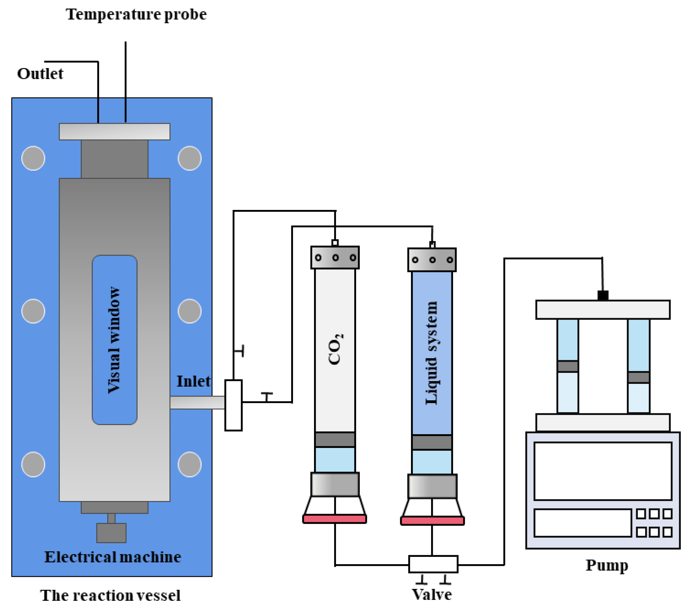
2.2. Experimental
2.3. Molecular Dynamics Simulation
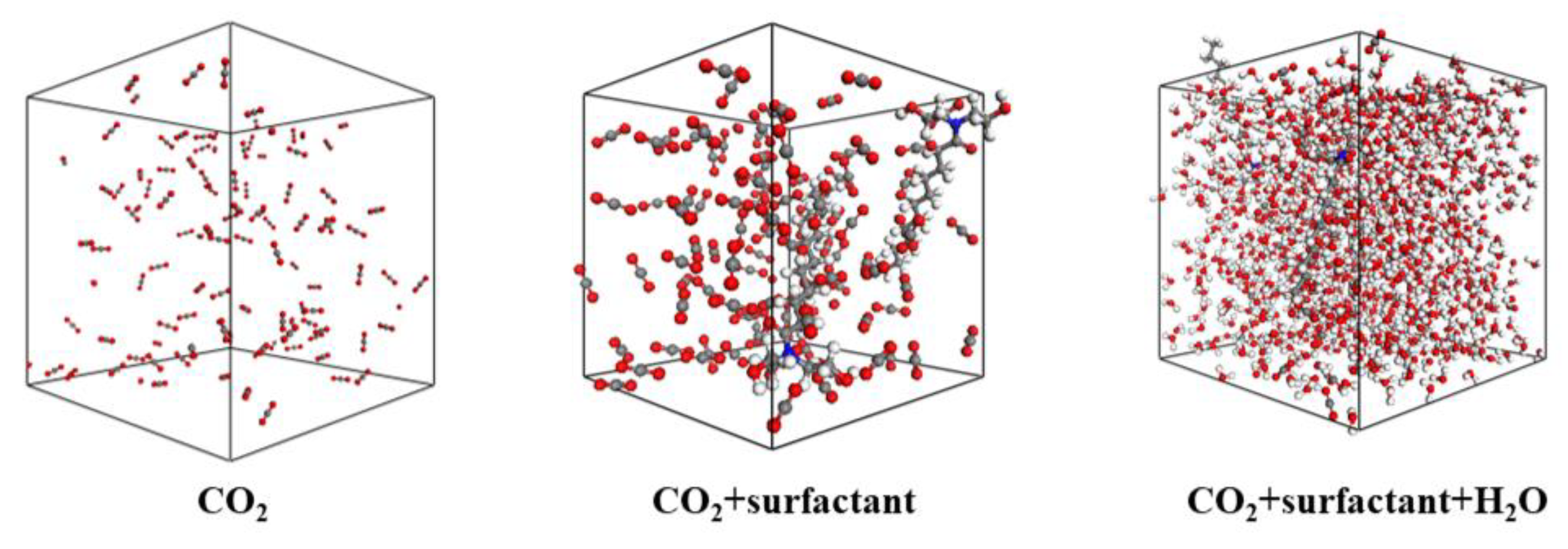
2.3.1. Model
2.3.2. Process
- (1)
- The initial model was constructed based on the basic physical properties of substances in the National Institute of Standards and Technology (NIST) database, and geometric optimization was performed;
- (2)
- The system underwent 10 cycles of annealing, gradually increasing from 298 to 500 K and then returning to 298 K in order to achieve equilibrium;
- (3)
- When the system was an NPT ensemble, 298 K, 0.1 MPa, and the time step was set to 1 fs, the molecular dynamics simulation process was a total of 5000 ps. The force field verification is shown in Table 2.
2.3.3. Calculation Method
3. Results and Discussion
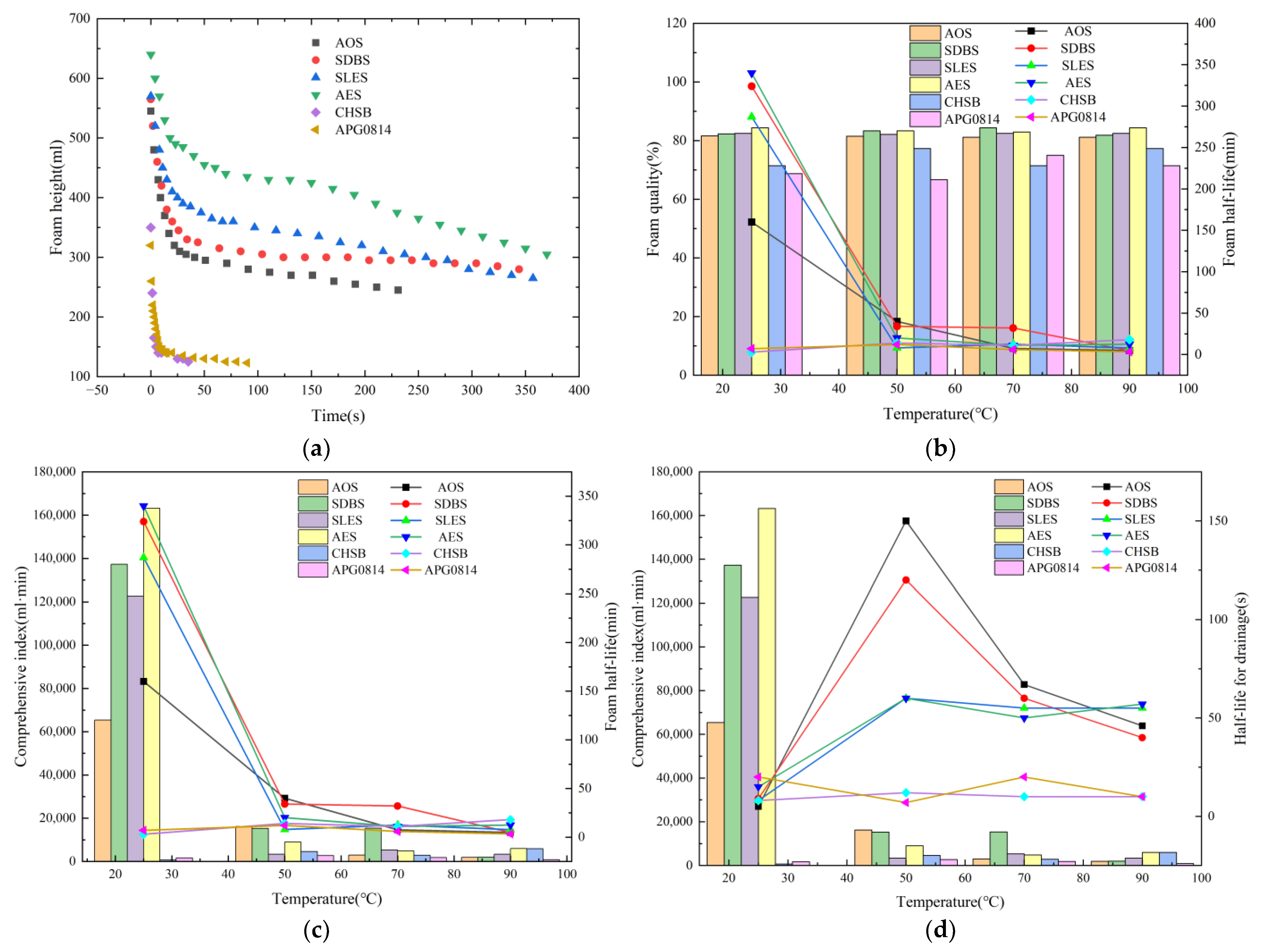
3.1. Foam Properties of Different Surfactants
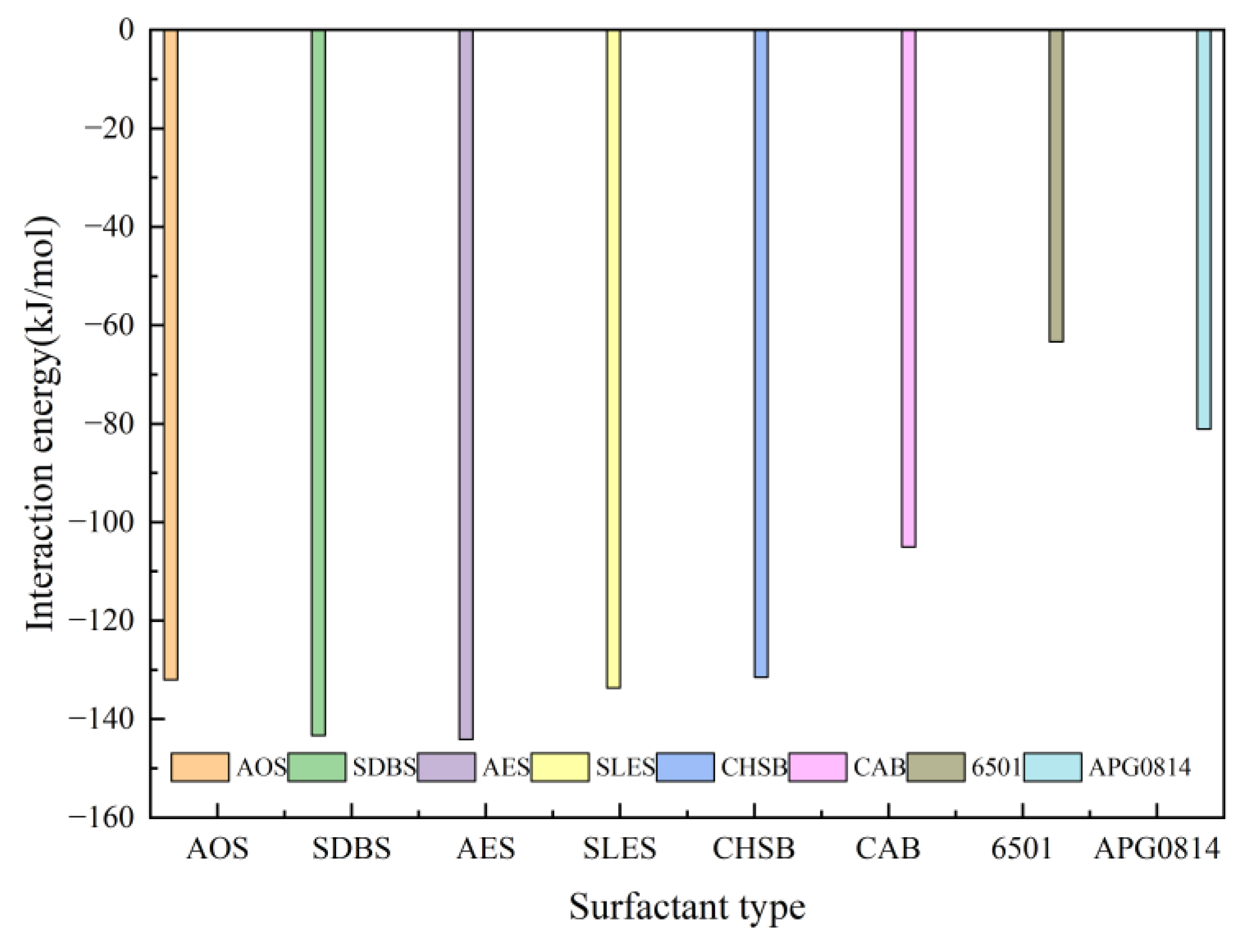
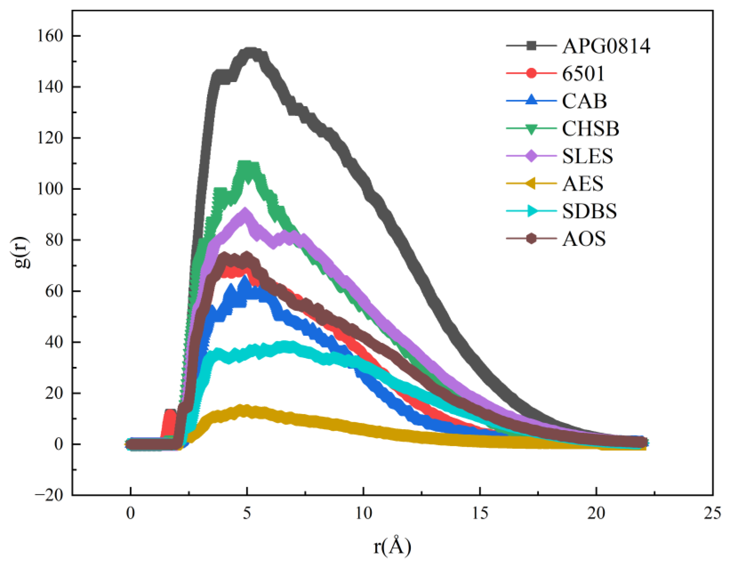
3.2. The Interaction between the Surfactant and CO2
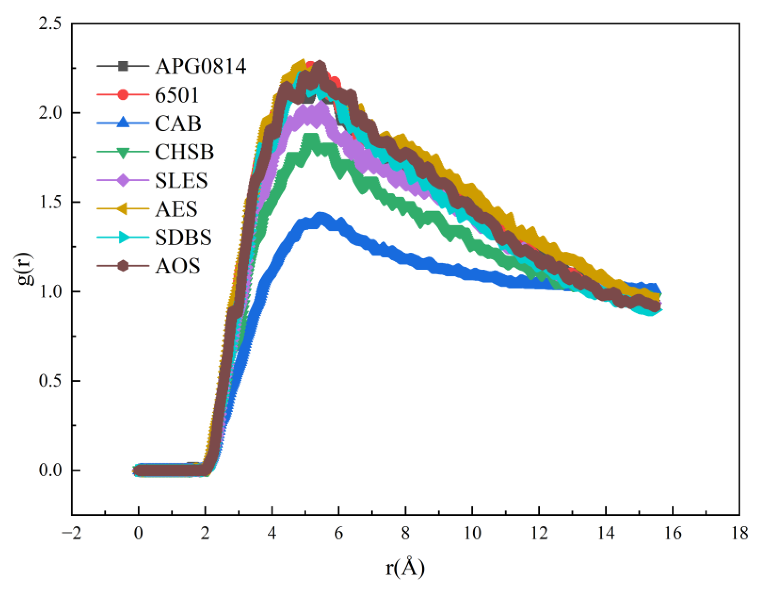
3.3. The Interaction between the Surfactant and CO2 under Aqueous Conditions
4. Conclusions
- Compared to non-ionic surfactants with certain steric hindrance, ionic surfactants with a simple linear structure exhibit better foaming performance but poorer foam stability. Concurrently, high temperatures are detrimental to the stability of CO2 foam, while higher pressures are beneficial;
- The mechanism of action of CO2 foaming agents depends on the balance among the interactions between CO2 and surfactant molecules, CO2 and water molecules, and the surfactant and water molecules. All substances formed dispersed systems of various aggregates in water rather than simply dissolving;
- Classical hydrogen bonding theories and the HLB (hydrophilic–lipophilic balance) theory are not applicable to the selection of CO2 foaming agents. It was found that the presence of EO (ethylene oxide) groups, which are CO2-philic, is advantageous for foaming in CO2 environments, and the formation of hydrogen bonds can enhance the stability of CO2 foam.
Author Contributions
Funding
Data Availability Statement
Conflicts of Interest
References
- Tong, X.; Zhang, G.; Wang, Z.; Wen, Z.; Tian, Z.; Wang, H.; Ma, F.; Wu, Y. Distribution and Potential of Global Oil and Gas Resources. Pet. Explor. Dev. 2018, 45, 779–789. [Google Scholar] [CrossRef]
- Zhao, J.; Ren, L.; Jiang, T.; Hu, D.; Wu, L.; Wu, J.; Yin, C.; Li, Y.; Hu, Y.; Lin, R.; et al. Ten years of Gas Shale Fracturing in China: Review and Prospect. Nat. Gas Ind. B 2022, 9, 158–175. [Google Scholar] [CrossRef]
- Lei, Q.; Yang, L.; Duan, Y.; Weng, D.; Wang, X.; Guan, B.; Wang, Z.; Guo, Y. The “Fracture-Controlled Reserves” Based Stimulation Technology for Unconventional Oil and Gas Reservoirs. Pet. Explor. Dev. 2018, 45, 770–778. [Google Scholar] [CrossRef]
- Lei, Q.; Weng, D.; Xiong, S.; Liu, H.; Guan, B.; Deng, Q.; Yan, X.; Liang, H.; Ma, Z. Progress and Development Directions of Shale Oil Reservoir Stimulation Technology of China National Petroleum Corporation. Pet. Explor. Dev. 2021, 48, 1198–1207. [Google Scholar] [CrossRef]
- Barati, R.; Liang, J.-T. A Review of Fracturing Fluid Systems Used for Hydraulic Fracturing of Oil and Gas Wells. J. Appl. Polym. Sci. 2014, 131, 40735. [Google Scholar] [CrossRef]
- Mian, C.; Hongkui, G.; Jinzhou, Z.; Jun, Y. The Key Fundamentals for the Efficient Exploitation of Shale Oil and Gas and Its Related Challenges. Pet. Drill. Tech. 2015, 43, 7–14. [Google Scholar]
- Burke, L.H.; Nevison, G.W.; Peters, W.E. Improved Unconventional Gas Recovery with Energized Fracturing Fluids: Montney Example. In Proceedings of the SPE Eastern Regional Meeting, Columbus, OH, USA, 17 August 2011; p. SPE-149344-MS. [Google Scholar]
- Zhang, C.; Pathegama Gamage, R.; Perera, M.; Zhao, J. Characteristics of Clay-Abundant Shale Formations: Use of CO2 for Production Enhancement. Energies 2017, 10, 1887. [Google Scholar] [CrossRef]
- Zhang, C.P.; Liu, S.; Ma, Z.Y.; Ranjith, P.G. Combined Micro-Proppant and Supercritical Carbon Dioxide (SC-CO2) Fracturing in Shale Gas Reservoirs: A review. Fuel 2021, 305, 121431. [Google Scholar] [CrossRef]
- Guo, J.; Li, M.; Cong, L. Progress and development directions of fracturing flooding technology for tight reservoirs in China. Acta Pet. Sin. 2022, 43, 1788. [Google Scholar]
- Wang, H.; Li, G.; He, Z.; Shen, Z.; Li, X.; Zhang, Z.; Wang, M.; Yang, B.; Zheng, Y.; Shi, L. Analysis of mechanisms of supercritical CO2 fracturing. Rock Soil Mech. 2018, 39, 3589–3596. [Google Scholar]
- Sun, X.; Dai, C.; Sun, Y.; Du, M.; Wang, T.; Zou, C.; He, J. Wettability Alteration Study of Supercritical CO2 Fracturing Fluid on Low Permeability Oil Reservoir. Energy Fuels 2017, 31, 13364–13373. [Google Scholar] [CrossRef]
- Prasad, S.K.; Sangwai, J.S.; Byun, H.-S. A Review of the Supercritical CO2 Fluid Applications for Improved Oil and Gas Production and Associated Carbon Storage. J. CO2 Util. 2023, 72, 102479. [Google Scholar] [CrossRef]
- Abdelaal, A.; Aljawad, M.S.; Alyousef, Z.; Almajid, M.M. A Review of Foam-Based Fracturing Fluids Applications: From Lab Studies to Field Implementations. J. Nat. Gas Sci. Eng. 2021, 95, 104236. [Google Scholar] [CrossRef]
- Ahmed, S.; Elraies, K.A.; Hanamertani, A.S.; Hashmet, M.R.; Shafian, S.R.; Hsia, I.C. Investigation of Carbon Dioxide Foam Performance Utilizing Different Additives for Fracturing Unconventional Shales. In Proceedings of the Abu Dhabi International Petroleum Exhibition and Conference, Abu Dhabi, United Arab Emirates, 11 November 2019; p. D012S138R002. [Google Scholar]
- Wu, X.; Zhai, C.; Zheng, Y.; Chen, A.; Yu, X.; Xu, J.; Sun, Y.; Cong, Y.; Tang, W.; Liu, X. Effect of Different Salt Ions with Different Concentrations on the Stability of Carbon Dioxide-In-Water Foam Fracturing Fluids. J. Mol. Liq. 2023, 373, 121215. [Google Scholar] [CrossRef]
- Zhao, J.; Wu, T.; Pu, W.; Daijun, D.; Chen, Q.; Chen, B.; Li, J.; Huang, Y. Application Status and Research Progress of CO2 Fracturing Fluid in Petroleum Engineering: A Brief Review. Petroleum 2024, 10, 1–10. [Google Scholar] [CrossRef]
- Pu, W.; Wu, T.; Zhao, J.; Gao, H.; He, M.; He, Y.; Chen, Y.; Zhu, Y. Nano-Structure of Hydrolyzed Polyacrylamide Strengthened Ultra Stable Nitrogen foam: Lab Experiments and Molecular Dynamics Simulation. J. Mol. Liq. 2024, 396, 124103. [Google Scholar] [CrossRef]
- Liu, B.; Wang, Y.; Liang, L.; Zeng, Y. Achieving Solubility Alteration with Functionalized Polydimethylsiloxane for Improving the Viscosity of Supercritical CO2 Fracturing Fluids. RSC Adv. 2021, 11, 17197–17205. [Google Scholar] [CrossRef] [PubMed]
- Hu, D.; Sun, S.; Yuan, P.-Q.; Zhao, L.; Liu, T. Exploration of CO2-Philicity of Poly(Vinyl Acetate-Co-Alkyl Vinyl Ether) through Molecular Modeling and Dissolution Behavior Measurement. J. Phys. Chem. B 2015, 119, 12490–12501. [Google Scholar] [CrossRef]
- Hoover, W.G. Canonical Dynamics: Equilibrium Phase-Space Distributions. Phys. Rev. A 1985, 31, 1695–1697. [Google Scholar] [CrossRef]
- Berendsen, H.J.C.; Postma, J.P.M.; Van Gunsteren, W.F.; DiNola, A.; Haak, J.R. Molecular Dynamics with Coupling to an External Bath. J. Chem. Phys. 1984, 81, 3684–3690. [Google Scholar] [CrossRef]
- Karasawa, N.; Goddard, W.A. Acceleration of Convergence for Lattice Sums. J. Phys. Chem. 1989, 93, 7320–7327. [Google Scholar] [CrossRef]
- Kong, W.; Lv, B.; Jing, G.; Zhou, Z. How to Enhance the Regenerability of Biphasic Absorbents for CO2 Capture: An Efficient Strategy by Organic Alcohols Activator. Chem. Eng. J. 2022, 429, 132264. [Google Scholar] [CrossRef]
- Wu, H.; Zhang, X.; Xu, D.; Li, B.; Jiang, Z. Enhancing the Interfacial Stability and Solvent-Resistant Property of PDMS/PES Composite Membrane by Introducing a Bifunctional Aminosilane. J. Membr. Sci. 2009, 337, 61–69. [Google Scholar] [CrossRef]
- Tubman, N.M.; Liberatore, E.; Pierleoni, C.; Holzmann, M.; Ceperley, D.M. Molecular-Atomic Transition along the Deuterium Hugoniot Curve with Coupled Electron-Ion Monte Carlo Simulations. Phys. Rev. Lett. 2015, 115, 045301. [Google Scholar] [CrossRef] [PubMed]
- Zhang, G.; Wu, T.; Li, J.; Pang, Q.; Yang, H.; Liu, G.; Huang, H.; Zhu, Y. Dynamics Simulation of the Effect of Cosolvent on the Solubility and Tackifying Behavior of PDMS Tackifier in Supercritical CO2 Fracturing Fluid. Colloids Surf. Physicochem. Eng. Asp. 2023, 662, 130985. [Google Scholar] [CrossRef]
- Dai, X.; Guo, Z.; Liu, W. Ultraviolet-Driven Janus Foams with Wetting Gradients: Unidirectional Penetration Control for Underwater Bubbles. ACS Appl. Mater. Interfaces 2022, 14, 42734–42743. [Google Scholar] [CrossRef]
- Myers, D. Surfaces, Interfaces, and Colloids: Principles and Applications, 1st ed.; Wiley: Hoboken, NJ, USA, 2002; ISBN 978-0-471-33060-8. [Google Scholar]
- Monsalve, A.; Schechter, R.S. The Stability of Foams: Dependence of Observation on the Bubble Size Distribution. J. Colloid Interface Sci. 1984, 97, 327–335. [Google Scholar] [CrossRef]
- Zhang, Y.; Song, H.; Li, D.; Zhang, L.; Yang, C.; Li, X.; Ren, X. Experiment on High Pressure CO2 Foam Stability of Nonionic Surfactants. J. China Univ. Pet. 2013, 37, 119–123+128. [Google Scholar]
- Jing, J.; Sun, J.; Zhang, M.; Wang, C.; Xiong, X.; Hu, K. Preparation and Rheological Properties of a Stable Aqueous Foam System. RSC Adv. 2017, 7, 39258–39269. [Google Scholar] [CrossRef]
- Zhai, Y.; Gao, Y.; Jiang, W.; Yi, W. Effects of Surfactants with Different HLB Values on LiNi0.8Co0.1Mn0.1O2. Mater. Rep. 2023, 37 (Suppl. S1), 24–26. [Google Scholar]
- Lin, Z.; Xu, F.; Wang, L.; Hu, L.; Zhu, L.; Tan, J.; Li, Z.; Zhang, T. Characterization of Oil Component and Solid Particle of Oily Sludge Treated by Surfactant-Assisted Ultrasonication. Chin. J. Chem. Eng. 2021, 34, 53–60. [Google Scholar] [CrossRef]
- Alex, M.; Kareth, S.; Petermann, M. Stability of Emulsions in Presence of Compressed Propane. J. Supercrit. Fluids 2012, 66, 282–290. [Google Scholar] [CrossRef]
- Huang, Q.; Wang, M.; Zhang, C.; Wang, Z.; Liu, B.; Lu, Z. Irritation and Interfacial Properties of Glucose Ester Surfactant. J. South China Univ. Technol. (Nat. Sci. Ed.) 2021, 49, 8–15. [Google Scholar]
- Luo, Z.; Su, Y.; Yue, S.; Yu, Q.; Tursun, R.; Zhang, J. Effect of Fluorocarbon Surfactant on Electroforming of Copper Nano-Powders. Int. J. Electrochem. Sci. 2021, 16, 210232. [Google Scholar] [CrossRef]


| System | Composition | No. of CO2 Molecules | No. of Surfactant Units | No. of H2O Molecules |
|---|---|---|---|---|
| 1 | CO2 | 100 | 0 | 0 |
| 2 | CO2/AOS | 100 | 2 | 0 |
| 3 | CO2/SDBS | 100 | 2 | 0 |
| 4 | CO2/AES | 100 | 2 | 0 |
| 5 | CO2/SLES | 100 | 2 | 0 |
| 6 | CO2/CHSB | 100 | 2 | 0 |
| 7 | CO2/CAB | 100 | 2 | 0 |
| 8 | CO2/6501 | 100 | 2 | 0 |
| 9 | CO2/0814 | 100 | 2 | 0 |
| 10 | CO2/AOS/H2O | 100 | 2 | 1000 |
| 11 | CO2/SDBS/H2O | 100 | 2 | 1000 |
| 12 | CO2/AES/H2O | 100 | 2 | 1000 |
| 13 | CO2/SLES/H2O | 100 | 2 | 1000 |
| 14 | CO2/CHSB/H2O | 100 | 2 | 1000 |
| 15 | CO2/CAB/H2O | 100 | 2 | 1000 |
| 16 | CO2/6501/H2O | 100 | 2 | 1000 |
| 17 | CO2/0814/H2O | 100 | 2 | 1000 |
| Fluid Type | NIST (g/cm3) | Value of Simulation (g/cm3) | Error (%) |
|---|---|---|---|
| H2O | 0.9971 | 0.9781 | 1.906% |
| CO2 | 0.0018 | 0.0017 | 5.556% |
| System | Evan /(J/m3) | Eelect /(J/m3) | Eother /(J/m3) | CED /(J/m3) | δ /(J/m3)1/2 |
|---|---|---|---|---|---|
| CO2 + AOS | 1.627 × 10⁶ | 6.443 × 10⁶ | 5.611 × 10² | 8.071 × 10⁶ | 2.841 |
| CO2 + SDBS | 1.377 × 10⁷ | 5.611 × 10⁷ | 3.612 × 10⁴ | 6.992 × 10⁷ | 8.362 |
| CO2 + AES | 3.333 × 10⁶ | 9.807 × 10⁶ | 6.459 × 10³ | 1.315 × 10⁷ | 3.626 |
| CO2 + SLES | 3.321 × 10⁶ | 1.292 × 10⁷ | 1.896 × 10³ | 1.624 × 10⁷ | 4.030 |
| CO2 + CHSB | 4.04 × 10⁶ | 6.832 × 10⁶ | 2.266 × 10³ | 1.087 × 10⁷ | 3.298 |
| CO2 + CAB | 2.291 × 10⁶ | 3.394 × 10⁶ | 7.407 × 10² | 5.686 × 10⁶ | 2.385 |
| CO2 + 6501 | 3.732 × 10⁵ | 3.509 × 10⁵ | 7.836 × 101 | 7.241 × 10⁵ | 0.851 |
| CO2 + 0814 | 5.843 × 10⁵ | 6.006 × 10⁵ | 9.381 × 101 | 1.185 × 10⁶ | 1.089 |
| System | Evan /(J/m3) | Eelect /(J/m3) | Eother /(J/m3) | CED /(J/m3) | δ /(J/m3)1/2 |
|---|---|---|---|---|---|
| CO2 + AOS + H2O | 0.377 × 10⁹ | 1.734 × 10⁹ | 2.982 × 10⁶ | 2.114 × 10⁹ | 45.978 |
| CO2 + SDBS + H2O | 0.376 × 10⁹ | 1.864 × 10⁹ | 3.369 × 10⁶ | 2.280 × 10⁹ | 47.751 |
| CO2 + AES + H2O | 0.382 × 10⁹ | 1.808 × 10⁹ | 3.316 × 10⁶ | 2.213 × 10⁹ | 47.042 |
| CO2 + SLES + H2O | 0.404 × 10⁹ | 1.851 × 10⁹ | 3.344 × 10⁶ | 2.259 × 10⁹ | 47.534 |
| CO2 + CHSB + H2O | 1.061 × 10⁹ | 1.069 × 10⁹ | 3.292 × 10⁶ | 2.133 × 10⁹ | 46.180 |
| CO2 + CAB + H2O | 1.122 × 10⁹ | 1.086 × 10⁹ | 3.396 × 10⁶ | 2.211 × 10⁹ | 47.02 |
| CO2 + 6501 + H2O | 1.091 × 10⁹ | 1.095 × 10⁹ | 3.343 × 10⁶ | 2.186 × 10⁹ | 46.758 |
| CO2 + 0814 + H2O | 1.005 × 10⁹ | 1.01 × 10⁹ | 2.973 × 10⁶ | 2.014 × 10⁹ | 44.881 |
Disclaimer/Publisher’s Note: The statements, opinions and data contained in all publications are solely those of the individual author(s) and contributor(s) and not of MDPI and/or the editor(s). MDPI and/or the editor(s) disclaim responsibility for any injury to people or property resulting from any ideas, methods, instructions or products referred to in the content. |
© 2024 by the authors. Licensee MDPI, Basel, Switzerland. This article is an open access article distributed under the terms and conditions of the Creative Commons Attribution (CC BY) license (https://creativecommons.org/licenses/by/4.0/).
Share and Cite
Zhou, L.; Chen, P.; Wu, T. An Experiment and Molecular Dynamics Simulation of Synergistic Foaming between a Surfactant and CO2 and the Structure–Activity Effect. Energies 2024, 17, 2465. https://doi.org/10.3390/en17112465
Zhou L, Chen P, Wu T. An Experiment and Molecular Dynamics Simulation of Synergistic Foaming between a Surfactant and CO2 and the Structure–Activity Effect. Energies. 2024; 17(11):2465. https://doi.org/10.3390/en17112465
Chicago/Turabian StyleZhou, Lang, Pengfei Chen, and Tong Wu. 2024. "An Experiment and Molecular Dynamics Simulation of Synergistic Foaming between a Surfactant and CO2 and the Structure–Activity Effect" Energies 17, no. 11: 2465. https://doi.org/10.3390/en17112465
APA StyleZhou, L., Chen, P., & Wu, T. (2024). An Experiment and Molecular Dynamics Simulation of Synergistic Foaming between a Surfactant and CO2 and the Structure–Activity Effect. Energies, 17(11), 2465. https://doi.org/10.3390/en17112465