Article

Numerical Investigation of Rotor and Stator Matching Mode on the Complex Flow Field and Pressure Pulsation of a Vaned Centrifugal Pump

1
School of Energy and Power Engineering, Jiangsu University, Zhenjiang 212013, China
2
Suzhou Lvkon Transmission S&T, Co., Ltd., Suzhou 215299, China
*
Author to whom correspondence should be addressed.
Energies 2024, 17(10), 2416; https://doi.org/10.3390/en17102416
Submission received: 30 April 2024 / Revised: 13 May 2024 / Accepted: 15 May 2024 / Published: 17 May 2024
(This article belongs to the Section F: Electrical Engineering)

Abstract

:
The match of rotor and stator blades significantly affects the flow field structure and flow-induced pressure pulsation characteristics inside the pump. In order to study the effects of the rotor and stator matching mode on the complex flow field and pressure pulsation of a centrifugal pump with a vaned diffuser, this paper designs three different vaned diffusers (DY5, DY8 and DY9) and uses the DDES (Delayed Detached Eddy Simulation) numerical method combined with structured grids to simulate the unsteady flow phenomena of the model pump under rated conditions. The results show that, under different rotor and stator matching modes, the pressure pulsation spectrum is dominated by the blade passing frequency and its harmonics. The matching mode of the rotor and stator significantly affects the time–frequency domain characteristics of the pressure pulsation inside the pump, and it is observed that the pressure pulsation energy of vaned diffusers with more blades is significantly smaller than that of fewer-blade vaned diffusers in comparison to the energy of the pressure pulsation at the blade passing frequency and within the 10–1500 Hz frequency band. Combined with the distribution characteristics of the complex flow field inside the pump, it can be found that increasing the number of vaned diffuser blades can reduce the energy of flow-induced pressure pulsation, improve the distribution of high-energy vortices in the interaction zone and stabilize the flow inside the centrifugal pump effectively.

1. Introduction

Centrifugal pumps, as universal fluid machinery, are critical equipment in fields such as industry, nuclear energy and agriculture [1]. With the development of pumps towards high speeds and power density, the requirements for the continuous, stable and safe operation of pumps are stringent [2]. The stability of the circulation system is directly influenced by centrifugal pumps, especially in applications with low vibration and noise. Therefore, revealing the complex flow field and flow excitation characteristics induced by rotor–stator interaction inside the centrifugal pump is of great significance for the design of low-noise pumps [3].
The vaned diffuser helps reduce the radial load on the impeller and contributes to the stable operation of the pump shaft. In large-scale water supply pumps, multi-stage pumps and nuclear power pumps, the centrifugal pump with a vaned diffuser is widely used. For a centrifugal pump equipped with a vaned diffuser, the stable operation of the pump is closely related to the complex internal flow, primarily caused by the RSI effect [4]. The strong flow field pulsation caused by the RSI effect will further be transmitted to the shaft system, leading to an alternating load, which is the main reason for abnormal pump vibration. The unsteady flow structures and pressure pulsations induced by rotor–stator interaction have been studied by many scholars [5], which is also associated to the pulsation capacity and the impedance of the hydraulic system [6]. Currently, scholars often use the Reynolds-averaged Navier–Stokes (RANS) turbulence model for simulating rotor–stator interaction [7,8]. Feng et al. studied the pressure pulsations and flow distribution of a centrifugal pump with a vaned diffuser under partial load conditions using the RANS model [9]. Jiang et al. analyzed the clocking effect of the vaned diffuser on the internal flow, pressure pulsations and radial forces of the pump using the RANS model. The study confirmed that the clocking effect generated by the relative position of the vaned diffuser and tongue would affect the pump performance, particularly pressure pulsations and radial forces [10]. Gao et al. found, through RANS numerical calculations, that a reasonable shape of the impeller outlet can improve the pump performance, reduce the pressure pulsation energy and better decrease the blade passing frequency amplitude and the trailing edge vortex intensity at the impeller outlet, suppressing the jet–wake structure [11]. Barrio et al. conducted unsteady numerical calculations on a centrifugal pump using the RANS method and obtained the influence of impeller sweeping over the tongue on flow field pulsations [12].
With the improvement of computer performance, it has become possible for researchers to explore complex flow structures using advanced CFD technology. In the field of multiphase flow, a high shear flow structure based on the internal friction momentum transfer mechanism and liquid–solid traction force was constructed by Wu et al. using the CFD-EDM method [7]. Yan et al. proposed a coupling modeling and solution method of computational fluid dynamics and a discrete element method (CFD-DEM) based on the particle porosity model, obtaining the mass transfer mechanism of the gas–liquid–solid mixed flow under dynamic vortex intensity regulation [8]. In the field of centrifugal pumps, Kye et al. accurately captured the trailing edge vortex at the exit of the volute centrifugal pump impeller using LES coupled with the Immersed Boundary Method, with a focus on analyzing the interaction effects between the trailing edge vortex at the impeller outlet under off-design conditions and the trailing edge of adjacent blades and the leakage flow in the clearance gap [13]. Posa et al. investigated the influence of the vaned diffusers on the flow inside the centrifugal pump under different operating conditions based on LES numerical calculation methods, revealing flow separations and recirculation structures within the centrifugal pump [14,15]. Zhang conducted a detailed study on the hydraulic excitation characteristics of unsteady flow inside the centrifugal pump, analyzing the flow field structures inside the pump using LES numerical simulation methods, particularly providing a detailed analysis of the blade trailing edge vortex and its evolution process. By combining the pressure pulsation characteristics inside the pump, the formation mechanism of the rotor–stator interaction inside the pump was deeply analyzed [16]. Yuan et al. studied the vortex structures and irreversible losses inside the impeller of the centrifugal pump based on the DDES method, vortex identification method and entropy production analysis [17]. Zhang et al. obtained the velocity evolution characteristics of the impeller trailing edge vortex during the blade sweep process using DDES methods, elucidating the generation and evolution process of the impeller trailing edge vortex structure [18]. Li et al. explored the unsteady vortex structure and pressure pulsation characteristics of the centrifugal pump with a vaned diffuser based on DDES calculation methods [19].
Experiments are important research tools for revealing the structures of unsteady flows and the characteristics of turbulent pulsations. Non-intrusive measurement techniques such as PIV (Particle Image Velocimetry) and LDV (Laser Doppler Velocimetry) are powerful tools for elucidating complex flow patterns. Keller et al. conducted experimental studies on the interaction between the impeller and vaned diffuser inside a centrifugal pump using the PIV measurement method. The results indicated that the interaction between the impeller and the tongue is mainly determined by the shedding vortices at the trailing edge of the blades and their impact on the tongue, as well as cutting and deformation occurring when passing through the tongue [20]. Wu et al. utilized PIV technology to measure the complex flow field inside a centrifugal pump, depicting the flow field at the midsection of the impeller and its motion evolution at different time instants [21]. Feng et al. conducted measurements on the interaction phenomena between the impeller and the vaned diffuser using a two-dimensional LDV method, analyzing the effect of the vaned diffuser position on the fluid flow in the centrifugal pump [22,23]. Ni et al. [24] revealed the typical flow distribution in nuclear pumps under different flow rates using LDA. Liu [25] studied centrifugal pumps using LDA and pressure pulsation measuring technologies, and discovered large-scale flow separation phenomena within the diffuser section under low-flow conditions and the maximum flow field pulsation intensity near the diffuser outlet.
In conclusion, researchers have employed various means and different methods to study the complex internal flow and flow-induced characteristics inside centrifugal pumps, and have explored the effects of pressure pulsation. However, the complex internal flow and pressure pulsation characteristics of the centrifugal pump have not been fully revealed, especially for the role of the rotor–stator interaction pattern on the complex flow field and the pressure pulsation inside the pump. The study of the relationship between the complex characteristic frequencies induced by different rotor–stator interaction patterns and the flow mechanisms is an important research content to achieve a low-pressure pulsation pump and requires further exploration. Therefore, this study utilizes the DDES method combined with structured grids to predict the precise flow pattern and unsteady pressure pulsation characteristics for the centrifugal pump with different vaned diffusers. Finally, pressure pulsations at different monitoring points are discussed, and a detailed discussion of the velocity distribution and three-dimensional vortex structures inside the model pump is also provided.

2. Computational Setup

2.1. Model Pump Design

This article focuses on the centrifugal pump with a vaned diffuser operating, and its main parameters are shown in Table 1. Three vaned diffusers with different numbers of blades are proposed to investigate the impact of the rotor–stator matching mode on the complex flow field and pressure pulsation characteristics, with the impeller unchanged. The design of the vaned diffuser should guarantee the pump’s performance almost unchanged under the three blade numbers. Finally, it is determined that only the number of vaned diffuser blade Zs is changed, which are selected as Zs = 5, 8 and 9 for the three model pumps named as DY5, DY8 and DY9, respectively, as shown in Figure 1.
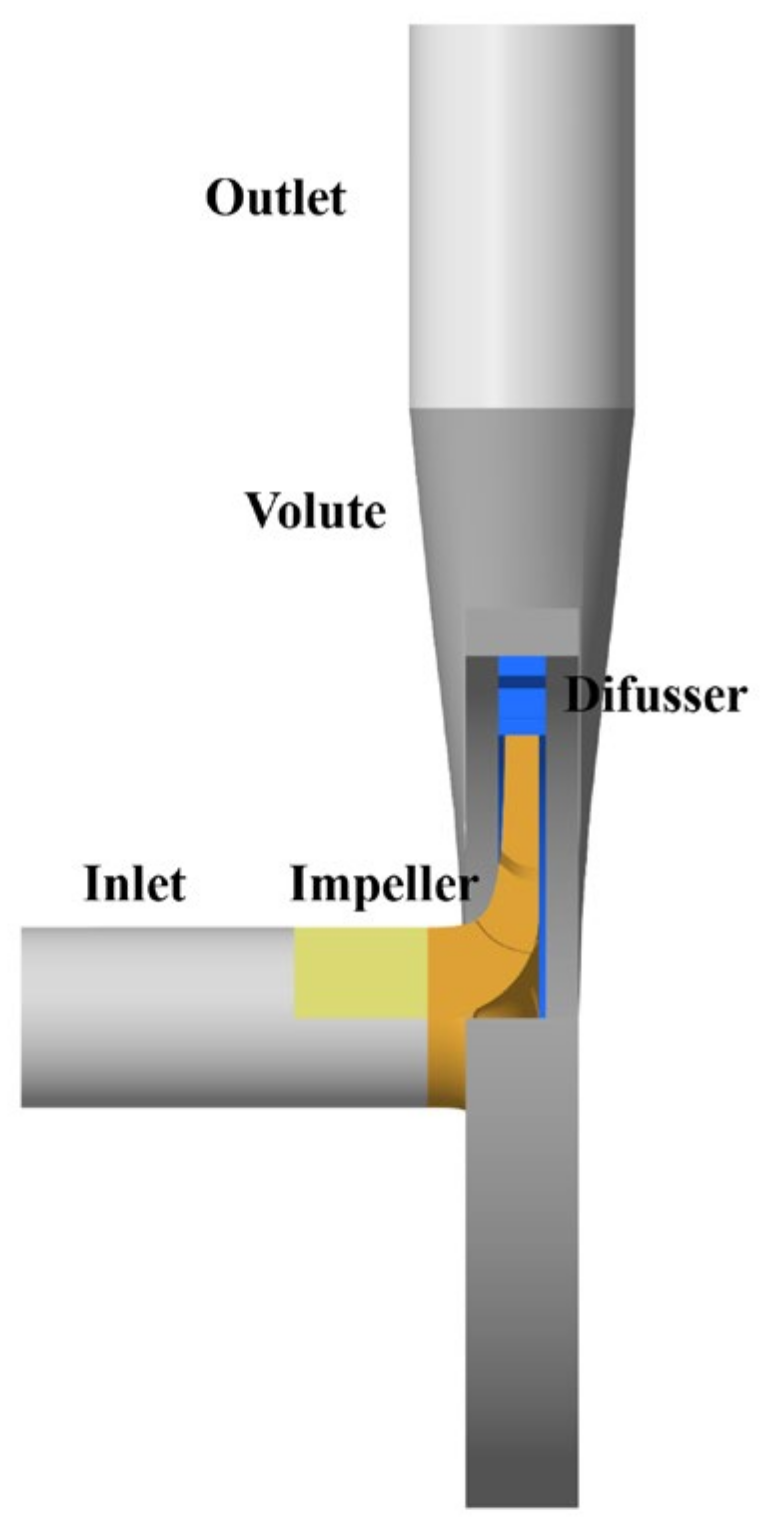
The geometric model of the model pump calculation domain is established as shown in Figure 2, where the impeller is the only rotating domain of the model pump.
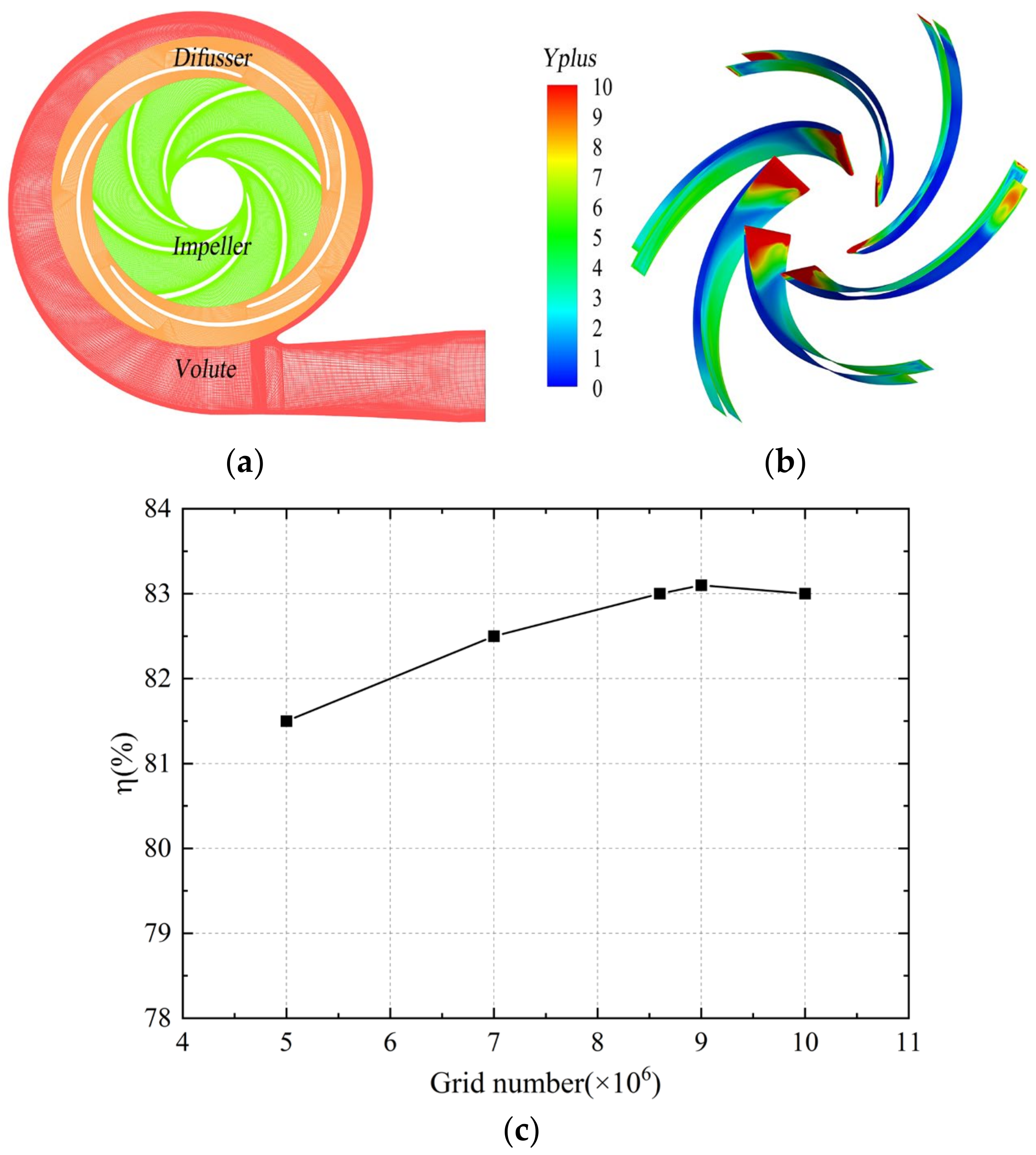
The mesh for each flow component was generated separately using ANSYS-ICEM, as shown in Figure 3a. Hexahedral structured meshes were utilized in the fluid domain with boundary layer refinement applied to the impeller surfaces, as shown in Figure 3b, where the average Y+ value on the blade surface was around 5.0, meeting the requirements for near-wall treatment. Mesh independence verification was conducted. Five different mesh grids from 5 million to 10 million were compared. It was observed that, when the total grid number reached 8.6 million, further increasing the mesh count resulted in minimal change in the efficiency, satisfying the criteria for mesh independence verification, as shown in Figure 3c. The efficiency difference was lower than 0.5%. Considering the calculation resources needed, a total grid number of 8.6 million cells was selected for the numerical simulation.

2.2. Calculation Method

The internal flow of the centrifugal pump belongs to unsteady, incompressible and viscous flow, with the main characteristic being turbulence. Therefore, in the present study, the flow control agenda selected was the Reynolds-averaged direction, with the assumption of the density as ρ , the pressure as P, the velocity component as u i , and the Reynolds stress as ρ u i u j ¯ , formulated as follows:
ρ t + t ( ρ u i ) = 0
t ( ρ u i ) + t ( ρ u i u j ) = ρ x i + x i ( u u i x j ρ u i u j ¯ )
When applying the Reynolds-averaged agenda, it is necessary to employ a turbulence model to solve the Reynolds stress terms. Therefore, in determining the turbulent flow control equations, the DDES method was utilized for the numerical calculation of the full channel model. The DDES method is as shown in the following [26].
ρ k t + ρ k u i t = x j μ + σ k μ t k x j + P k ρ k 3 / l D D E S
ρ ω t + ρ ω u i x i = x j μ + σ ω μ t ω x j ρ ω 2 β + ρ α μ t P k + 2 1 F 1 ρ σ ω 2 ω k x j ω x j
μ t = a 1 ρ k max ( a 1 ω , S F 2 )
In the formula, μ —viscosity of power, μ t —turbulent viscosity, S —adaptation rate, F 1 , F 2 —hybrid functions, F 1 = tanh min max k β ω y , 500 ν y 2 ω , 4 ρ σ ω 2 k C D k ω y 2 4 , and F 1 = tanh max k β ω y , 500 ν y 2 ω 2 .
The SIMPLIC algorithm was adopted using the MRF method to address the relative motion problem between the stationary domain and the motion domain. Due to the efficiency, reliability and ease of implementation of the SIMPLIC algorithm, the coupling between the speed and pressure was performed using the SIMPLIC algorithm. To ensure convergence, the second-order implicit scheme was used with a residual set to 10−6. The inlet was set as a velocity inlet with a turbulence intensity of 0.05 and the outlet was set as a free outflow. The DDES method was applied for unsteady calculations using steady-state calculation results as the initial values for unsteady calculations. The time step was set as the time t = 0.0001149 s for the impeller to rotate by 1°, and the convergence accuracy within each step was set to 2.0 × 10 6 .

2.3. Monitoring Points

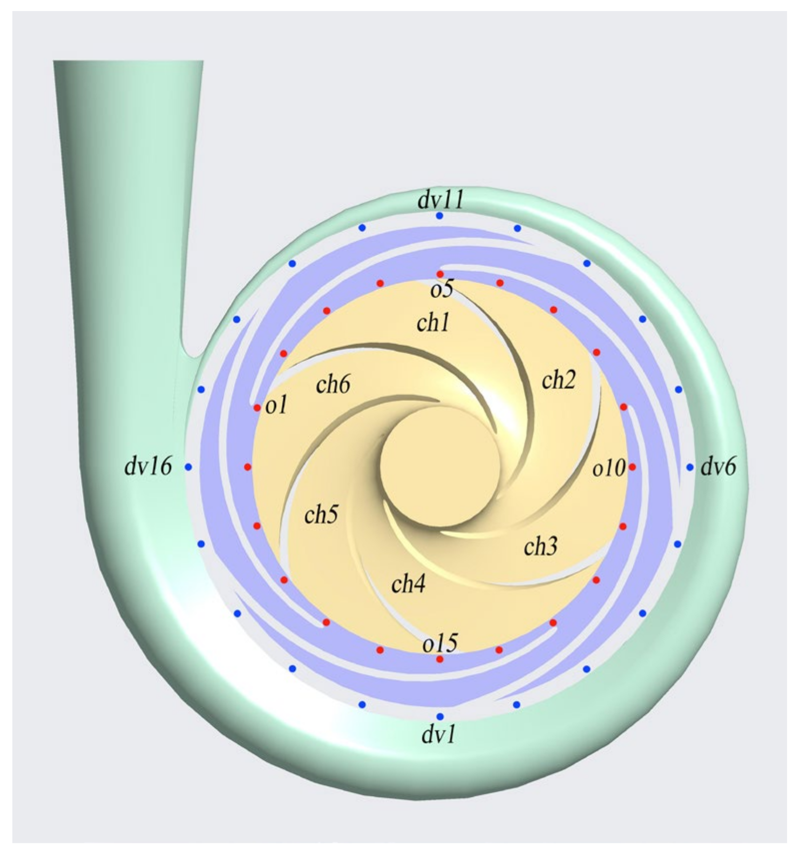
By arranging monitoring points at typical positions in the model pump calculation domain, the pressure pulsation characteristics inside the centrifugal pump were studied. Figure 4 shows the layout of the monitoring points for model pump DY5. Twenty monitoring points were evenly distributed in the gap between the impeller and the vaned diffuser of the model pump to analyze the rotor–stator interaction excitation characteristics of three model pumps. Along the circumferential direction at the exit of the vaned diffuser, twenty monitoring points were evenly distributed to obtain the pressure pulsation characteristics at the exit of the vaned diffuser. The arrangements of monitoring points in the vaned diffuser passage for model pumps DY8 and DY9 were consistent with DY5.

3. Experimental Test Loop

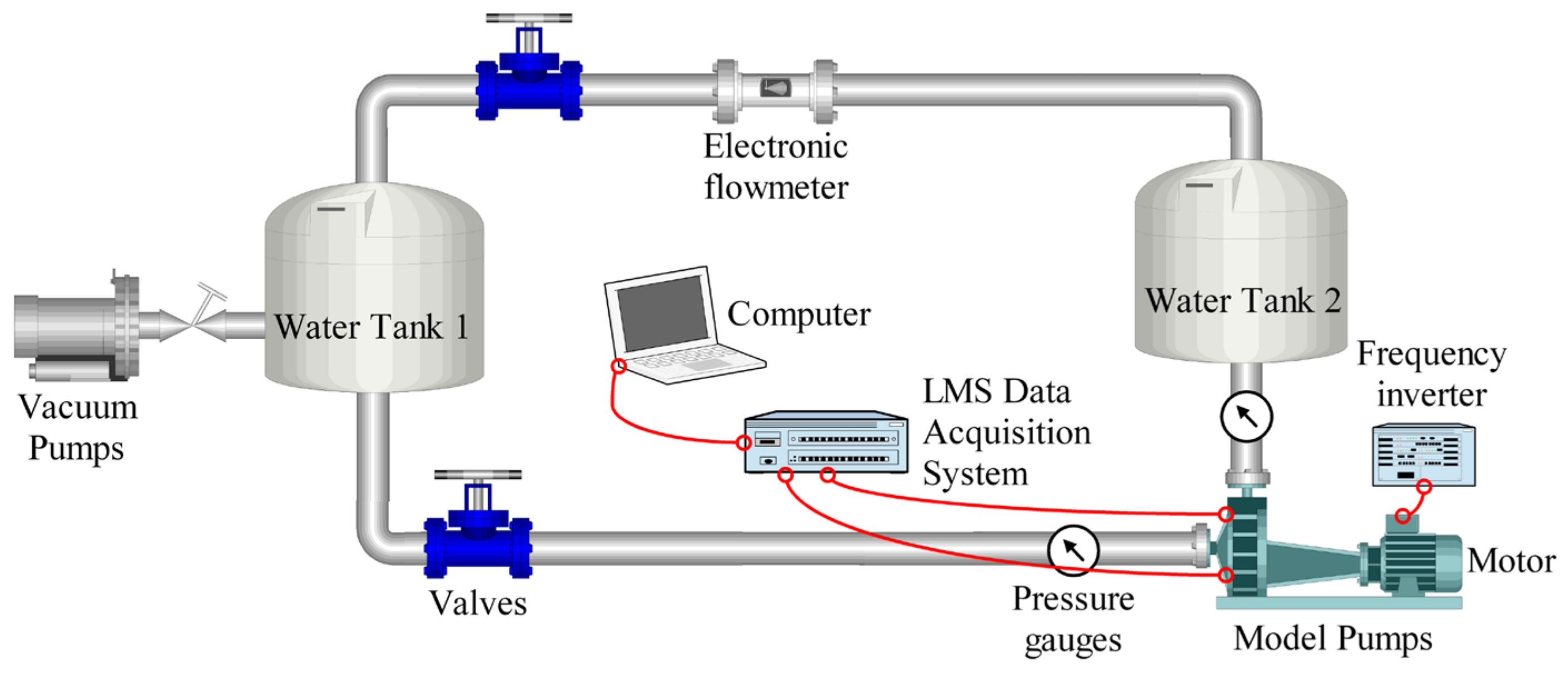
The closed test system of the centrifugal pump, as shown in Figure 5, was constructed. The flow rate and pump head were obtained using an electromagnetic flowmeter and a high-precision pressure gauge, while the input power of the pump was obtained using a torque meter. The error of the entire testing system was less than 0.5%. In order to obtain the spectral characteristics of the model pump under different operating conditions, a high-frequency pressure pulsation sensor (PCB113B27) was used to collect pressure signals. Due to the pump speed of 1450 r/min on this test platform and the maximum excitation frequency being lower than 1000 Hz [27,28], the spectrum bandwidth during the sampling process was set to 6400 Hz, and the sampling resolution was set to 0.5 Hz. The sampling time was 3 s and the time interval was 0.5 s to fully satisfy the Nyquist sampling theorem.

4. Results and Analysis

4.1. Prediction of Pump Performance

The dimensionless treatment was conducted on the flow rate and head, resulting in the flow rate coefficient and head coefficient, as shown in Equations (6) and (7):
Φ N = Q N u 2 R 2 2
Ψ = g H d u 2 2
In the formula, R2 is the impeller radius, 125 mm; u2 is the impeller outlet circumferential speed, 18.98 m/s.
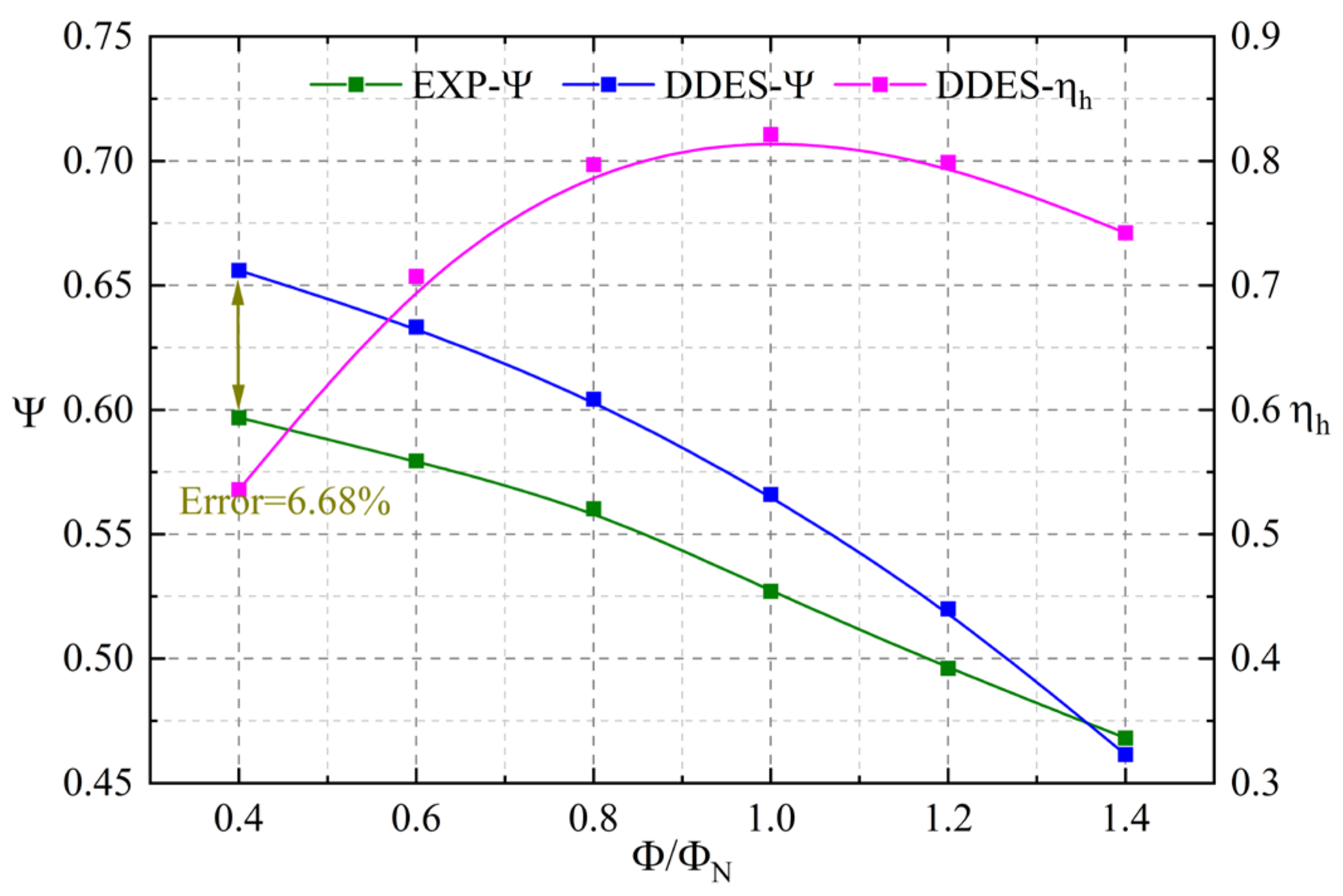
Figure 6 shows the head error between the experimental and numerical calculations of the DY5 model pump to validate the accuracy of the DDES method. It can be observed from the pump efficiency curve that the optimal efficiency point is located at the rated operating condition, with a maximum hydraulic efficiency of 82.4%. From the pump head curve, it is evident that the calculated head matches the experimental result. At 0.4 QN, the maximum error between the numerical calculation and experiment is 6.68%, which may be related to the leakage fluid between the impeller and the volute. The error at the design condition is attributed to the fact that the numerical calculation does not consider the impact of mechanical losses and leakage losses [29]. Leakage between the impeller and the volute is a significant factor affecting the calculation accuracy, which is not considered during the numerical simulation process.
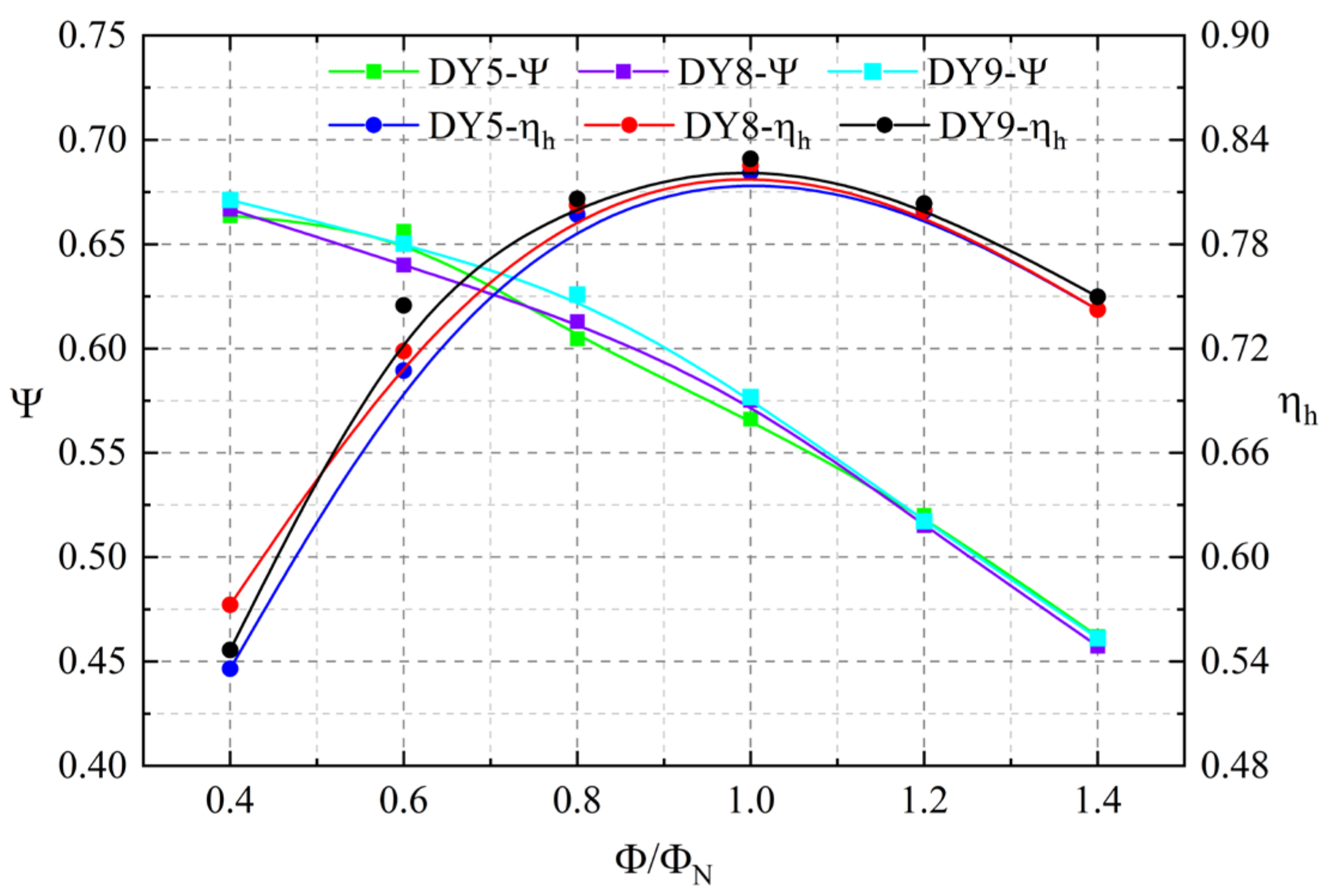
Figure 7 presents the performance prediction curves of different impeller–vaned diffuser matching models. It can be seen from the figure that, throughout the entire operating range, the head and efficiency curves of the three model pumps tend to be consistent with the high-efficiency points, all at 1.0 QN, meeting the design objectives and laying the foundation for subsequent unsteady numerical calculations. Under the design condition, with an increase in the number of vaned diffuser blades, both the head and efficiency increase. The head and efficiency of the DY9 scheme are approximately 2% and 1% higher than the DY5 model pump, as shown in Table 2. It can be inferred from the results that the impeller–vaned diffuser matching mode can affect the hydraulic performance of the pump.

4.2. Analysis of Pressure Pulsations

For the purpose of the analysis, the obtained pressure signal was made dimensionless, and the pressure fluctuation coefficient Cp was defined as follows:
C p = p p a v 0.5 ρ u 2 2
In the equation, p is the pressure at the monitoring point; pav is the average pressure at the monitoring point; ρ is the fluid density.
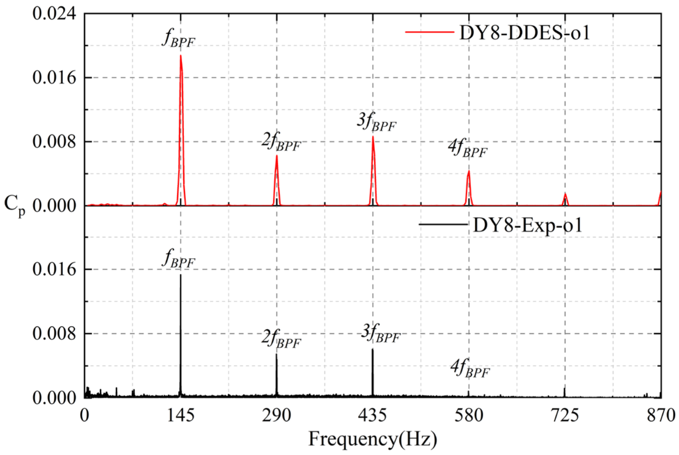
To verify the accuracy of the numerical calculation methods in predicting the pressure pulsation characteristics, Figure 8 first shows the pressure pulsation signals at monitoring point o1 located in the impeller outlet region under the rated operating condition for the DY8 model pump. The spectral characteristics of the numerical and experimental frequencies of the model pump exhibit typical discrete features, with peak signals mainly occurring at the blade passing frequency fBPF and its harmonics of 2fBPF, 3fBPF and 4fBPF, where the pressure pulsation amplitude at the blade passing frequency is significantly larger than at its higher harmonics. The DDES method can capture characteristic frequencies well and generally agree with those captured in the experiment. During the numerical calculations, the monitoring points are uniformly distributed at the impeller outlet. However, discrepancies in the positioning of the monitoring points during manufacturing processes compared to calculations can lead to errors between the experimental and numerical results. Furthermore, the high-frequency pressure pulsation sensor used in the experiment has a diameter of 6 mm, collecting the average value of pressure pulsation signals across the entire cross-section, while the DDES calculation is set for signals at individual points [30], leading to potential errors in the experiment and simulation due to different collection areas. The calculated error between the simulations and experiments at the blade passing frequency is only 18.18%, with errors below 32% at the higher harmonics, as shown in Table 3. Compared to the published literature, where errors in the pressure pulsation amplitude between calculations and experiments often exceeded 50% and even surpassed 100% [31], the calculation error in this study is not large for pressure pulsation prediction. Therefore, this study considers that the DDES numerical simulation method can effectively investigate the complex internal flow and pressure pulsation characteristics of centrifugal pumps.
Pressure pulsations inside the centrifugal pumps mainly originate from the strong RSI effect of the rotor and stator. Figure 9 shows the pressure pulsation signal at monitoring point o1 at the impeller outlet for three pumps. The corresponding frequency spectra are obtained after the FFT (Fast Fourier Transform) with the application of a Hanning window in the signal processing. The centrifugal pump studied in this paper has a speed of 1450 r/min, with a blade number Zr of 6; thus, the impeller rotational frequency fR is 24.2 Hz and the blade passing frequency fBPF is 145 Hz. It can be observed from the time-domain spectrum that, due to the strong RSI effect, periodic pressure signals are generated, and the alternating peaks and valleys are determined by the number of rotor and stator blades. In the time-domain plot, typical discrete characteristics are presented, with peak signals mainly occurring at the blade passing frequency fBPF and its harmonics 2fBPF, 3fBPF and 4fBPF. In the frequency spectra of the DY5 and DY8 pumps, the pressure pulsation amplitudes at fBPF are much greater than at their harmonics, while, in the spectrum of the DY9 model pump, the component at 3fBPF is captured.
Based on the above analysis, at the impeller outlet, the blade passing frequency signal is the dominant signal of pressure pulsation. In order to compare the effects of the three model pumps on the pressure pulsation signal at the impeller outlet, this study extracted the fBPF of measuring points o1~o20 for each model pump for comparison, as shown in Figure 10. It can be observed from the figure that the DY8 model pump shows a smoother circumferential distribution, with most monitoring points having a blade passing frequency amplitude around Cp = 0.015, without significant abrupt changes. Although the circumferential distribution of the blade passing frequency amplitude at the blade passing frequency for the DY9 model pump is similar in trend to that of the DY8 model pump, its overall blade passing frequency amplitude is greater than that of the DY8 model pump, with the amplitude of most monitoring points around Cp = 0.02, while the circumferential distribution of the blade passing frequency amplitude for the DY5 model pump shows the greatest variation, exhibiting significant abrupt changes. It was calculated that the average fBPF of the measuring points at the impeller outlet in the circumferential direction for the DY5 configuration is 0.018, for the DY8 model pump it is 0.016 and for the DY9 model pump it is 0.019. In summary, among the three model pumps with different vaned diffuser blades, the DY8 model pump exhibits the best suppression effect on the rotor–stator interaction at the impeller outlet, reducing the amplitude by 12% compared to the original DY5 model pump.
The pulsation characteristics at the vaned diffuser outlet are an important way to judge the effectiveness of suppressing the rotor–stator interaction inside the pump. To analyze the pressure pulsation characteristics at the vaned diffuser outlet, Figure 11 presents the pressure pulsation spectra at point dv1 of three model pumps. Similar to the pressure pulsation characteristics at the impeller outlet, in the time-domain signal, peaks and valleys alternate within one cycle, but the pattern of the DY9 model pump is not obvious. In the pressure spectra, the three model pumps all capture the fBPF, but with different patterns. The DY5 model pump captures higher components at 2fBPF, 3fBPF and 4fBPF. The DY8 model pump captures 3fBPF, while the amplitude of 2fBPF is not significant, and the DY9 model pump does not capture 3fBPF and has a very low amplitude at 2fBPF.
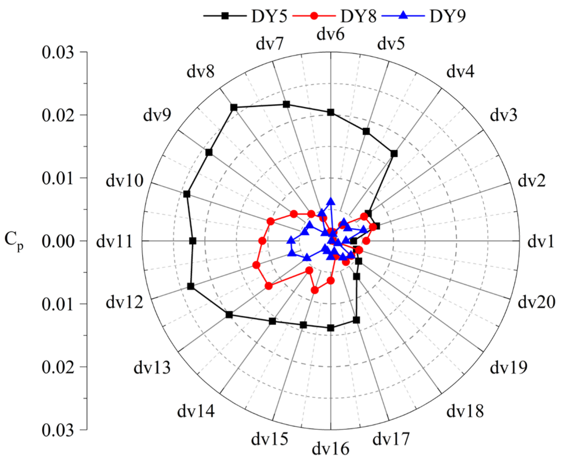
To better understand the suppression effect of the three model pumps on the pressure pulsation signals at the vaned diffuser outlet, the component amplitudes at fBPF of each model pump at the dv1~dv20 measurement points are extracted for comparison, as shown in Figure 12. It can be seen from the figure that the distribution of the blade passing frequency energy amplitude at the vaned diffuser outlet is significantly different. A steep change in the fBPF distribution is observed for the DY5 model pump. The fBPF distributions at each measurement point for the DY8 and DY9 model pumps are relatively flat, and it is still clear that the fBPF of the DY9 model pump is the smallest. Calculations show that the average fBPF of the vaned diffuser outlet of the DY5 model pump is 0.0155, 0.0061 for the DY8 mode pump and 0.0035 for the DY9 model pump. For the DY9 model pump, the reduction in the average amplitude reaches 78% compared to the original DY5 model pump.
Due to the occurrence of other signals in the spectrum, for a comprehensive and quantitative analysis of the energy distribution characteristics of the pressure pulsation of the model pumps with different vaned diffusers, the pressure pulsation energy in particular frequency band is quantitatively analyzed using the RMS method, as shown in Equation (9).
R M S = 1 2 1 2 A 1 2 + n = 2 n 1 A n 1 2 + 1 2 A n 2
At the beginning and end positions of the frequency band, A1 and An, respectively, represent the pressure pulsation amplitudes, with An−1 representing the pressure pulsation amplitude at different frequencies within the frequency band.
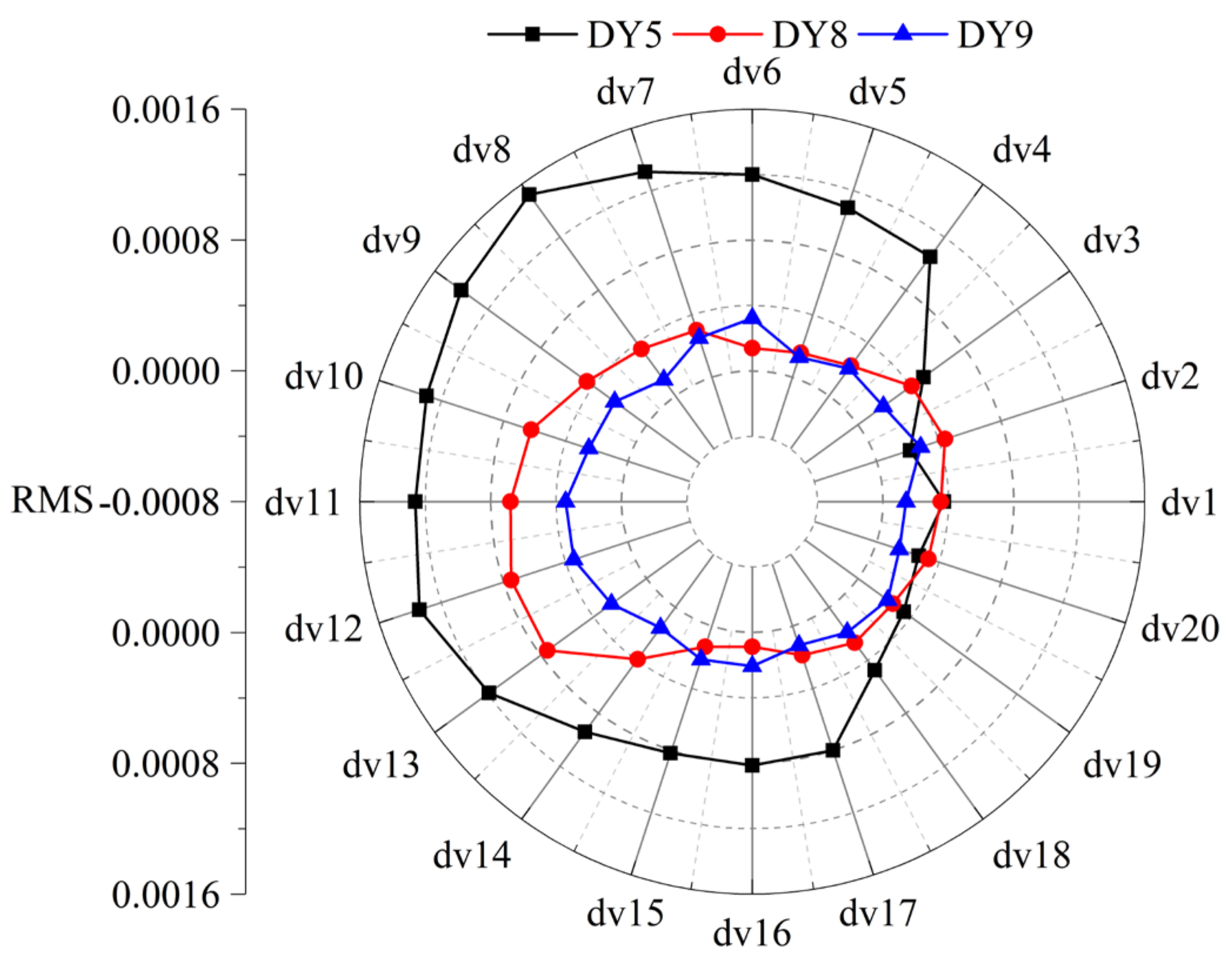
Figure 13 shows the RMS values within the frequency band of 10–1500 Hz for the three model pumps for the points at the diffuser outlet. It can be seen from the figure that the RMS values within the frequency band of 10–1500 Hz follow a similar pattern to the fBPF. The RMS values at measuring points are highest for the DY5 model pump, while the RMS values for the DY9 model pump are distributed evenly and with the smallest amplitudes. Calculations show that the average RMS values at the circumferential measuring points at the vaned diffuser outlet for the DY5 model pump is 0.0008454, and for the DY8 model pump it is 0.0003639. For the DY9 model pump, the RMS value is 0.0002170, resulting in 74% reduction in the amplitude compared to the original DY5 model pump. In conclusion, at the vaned diffuser outlet, the DY9 model pump exhibits the best suppression of the rotor–stator interaction, while the DY5 model pump performs the worst.
From the above analysis, it is concluded that the matching mode of the rotor and stator will affect the frequency spectrum. The dominant signals in the pressure pulsation spectrum are the blade passing frequency and its harmonics. The number of vaned diffuser blades affects the amplitude energy. A lower number of stator blades results in a poorer pressure pulsation performance with strong rotor–stator interaction. Therefore, the use of a higher number of stator blades should be considered in the design of low-noise pumps.

4.3. Unsteady Flow Characteristics

The impeller outlet region is an important area for studying the rotor–stator interaction, and the study of the flow field at the impeller outlet can provide a more intuitive comparison of the flow structures induced by the rotor–stator interaction of the three pumps. Figure 14, Figure 15 and Figure 16 show the evolution process of the relative velocity distribution at the impeller outlet of the three pump models, where δt represents the time step during the numerical simulation. From the figures, it can be observed that all three pump models exhibit distinct high-speed jet regions on the pressure side (PS) of the blade, and a low-speed wake region in the middle position on the suction side (SS) of the blade. Between the pressure side and suction side, the high-speed region adheres to the hub and shroud, with a strip-like high-speed band moving in the passage of the DY5 model pump. During the evolution process of the relative velocity of the model pumps, the high-speed band at hub and shroud of the DY5 model pump gradually stretches and almost fills the entire passage. Although the relative velocity evolution patterns of the three model pumps differ, the flow structures are consistent, and the distribution of the relative velocity along the axial position is similar, all exhibiting distinct non-uniform jet–wake phenomena.
In order to further reveal the unsteady flow structures inside the model pumps, this paper adopts the vortex structure identification technique Q criterion recognition method to capture the vortex structures in the interaction region and analyze in detail the evolution process of the vortex structures in that region. The Q criterion recognition method proposed by Hunt [32] is more conducive to identifying the rotation and deformation of flow field eddies, with its definition as follows:
Q = 1 2 B F 2 A F 2
where A means V , the symmetric matrix of the decomposition, and B means V , the anti-symmetric matrix of the decomposition; ║║F means the Frobenius paradigm of the matrix.
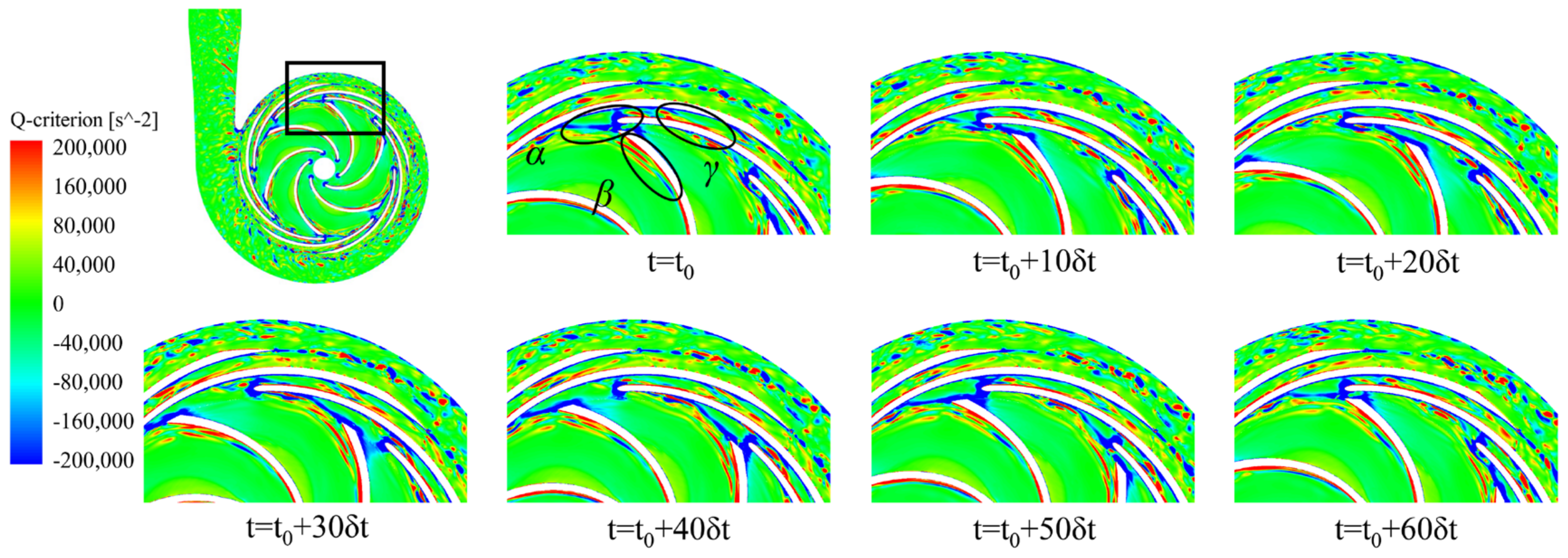
Figure 17, Figure 18 and Figure 19 show the evolution of the vortex structure of the three model pumps in the vaned diffuser under the design working condition. It can be seen from the figures that, at t = t0, the impeller blades of the three model pumps start to sweep the vaned diffuser inlet; at this time, the negative vortex on the trailing edge of the working surface of the impeller blades collides and squeezes the vaned diffuser inlet, where the vortex structure α is formed, and the positive vortex sheet β attached to the suction side of the blade starts to fall off. At the moment of t = t0 + 20δt, the impeller blade sweeps over the vaned diffuser inlet, and the negative vortex on the pressure surface of the blade collides with and squeezes the vaned diffuser inlet and divides into two parts, one part of which enters the impeller–diffuser gap along the vaned diffuser pressure surface, and the other part of which enters the vaned diffuser flow channel. Part of the shed vortex separated from the vortex band β enters the impeller–diffuser gap, and the other part collides and squeezes the vaned diffuser inlet, which has a strong interaction with the vortex α, resulting in high vortex energy near the vaned diffuser inlet. This phenomenon intuitively explains the phenomenon for the three model pumps, proposed above, which have a strong rotor–stator effect at the vaned diffuser inlet and a prominent amplitude of pressure pulsation signals. As the impeller continues to rotate, it is found that, in the process of t = t0 + 30δt~t = t0 + 50δt, the vortex sheet β at the blade suction and the negative vortex at the trailing edge at the pressure side are continuously shed, and the positive and negative vortices separated from these vortexes move to the gap, forming a new high-vortex region, with the collision with the next vaned diffuser to continue the evolution.
The differences between the vortices in the vaned diffuser passage are significant among the DY5, DY8 and DY9 model pumps. As the impeller passes through the entrance of the vaned diffuser, a high-energy vortex is formed at the entrance and starts moving into the vaned diffuser passage. The γ vortex in the vaned diffuser passage of all three model pumps evolves from the vortex α mentioned above. However, at t = t0 + 20δt, it is observed that, in the DY5 model pump, the γ vortex breaks into small vortices and a negative vortex detached from the pressure side of the vaned diffuser moves towards the exit. In contrast, in the DY8 and DY9 model pumps at that moment, the γ vortex still moves towards the exit with a distinct high-vortex sheet attached to the suction side of the vaned diffuser. When the impeller rotates at t = t0 + 50δt, the γ vortex in the DY8 and DY9 model pumps only separates into small vortices and negative vortices on the pressure side of the vaned diffuser. The impeller of the DY5 model pump has already generated a new cluster of positive vortices at the entrance of the vaned diffuser at t = t0 + 40δt, whereas, in the DY8 and DY9 model pumps, the cluster of positive vortices at the entrance of the vaned diffuser only begins to form after the interaction process of an impeller passage at t = t0 + 60δt. This indicates that the vortex energy at the entrance of the vaned diffuser is higher in the DY5 model pump, which will induce stronger flow field fluctuations. The lower vortex energy at the entrance of the vaned diffuser in the DY8 and DY9 model pumps shows that the matching mode of the rotor–stator has a very positive effect on improving the distribution of high-energy vortices in the interaction area and stabilizing the flow fluid in the centrifugal pump.

5. Conclusions

This article explores the pressure pulsation characteristics and complex flow structures inside the pump induced by different the matching modes of the rotor and stator based on the DDES numerical calculation method with the structured grid. The main conclusions include the following:
(1)
The numerical calculation method in this article is well matched with the experimental results, enabling the precise calculation of the complex flow field and pressure pulsation characteristics inside the pump.
(2)
The matching mode of the rotor and stator significantly affects the time–frequency domain characteristics of the pressure pulsation inside the pump. From the spectrum, it can be seen that the dominant signals in the pressure pulsation spectrum are the blade passing frequency and its harmonics.
(3)
Through the comparison and analysis of the pressure pulsation energy, it can be seen that the pressure pulsation energy of the DY8 and DY9 model pumps is less than that of the DY5 pump. This implies that appropriately increasing the number of vaned diffuser blades can reduce the pressure pulsation energy induced by the rotor–stator interaction. Therefore, for the design of a low-pressure pulsation pump, a greater number of blades should be adopted.
(4)
The flow structure of the three pumps is relatively consistent, with a high-speed jet zone appearing on the pressure side and a low-speed wake zone appearing around the suction side. Increasing the number of vaned diffusers improves the distribution of high-energy vortices in the interaction zone, which has a very positive effect on stabilizing the high-speed flow of the fluid inside the centrifugal pump, which is consistent with the conclusions of the pressure pulsation numerical calculations.

Author Contributions

Investigation, F.Z. and D.L.; writing—original draft, L.D.; writing—review and editing, N.Z. and M.G.; supervision, B.G. All authors have read and agreed to the published version of the manuscript.

Funding

This work is funded by the China Postdoctoral Science Foundation, No. 2023M731356, and the Natural Science Foundation of China, No. 52376024.

Institutional Review Board Statement

Not available.

Informed Consent Statement

Not available.

Data Availability Statement

The original contributions presented in the study are included in the article, further inquiries can be directed to the corresponding author.

Conflicts of Interest

Author Fankun Zheng was employed by the company Suzhou Lvkon Transmission S&T, Co., Ltd. The remaining authors declare that the research was conducted in the absence of any commercial or financial relationships that could be construed as a potential conflict of interest.

Nomenclature

QdFlow rate, m3/h
ndRotating speed, r/min
HdHead, m
nsSpecific speed
ΦNFlow coefficient
ΦFlow rate coefficient
ΨNHead coefficient
ΨPump head coefficient
ZrImpeller blade number
ZsDiffuser blade number
ηEfficiency
D1Impeller suction diameter, mm
D2Impeller exit diameter, mm
D3Diffuser outlet diameter, mm
D4Volute exit diameter, mm
R2Impeller outlet radius, mm
b2Impeller exit width, mm
b3Diffuser inlet width, mm
φVolute angle, °
ϕ Wrap angle of the blade, °
u2Speed at the impeller exit, m/s
β1Impeller inlet angle, °
β2Blade exit angle, °
β3Diffuser inlet angle, °
β4Diffuser outlet angle, °
ρ Water density, kg/m3
APressure value, Pa
CpPressure coefficient
Q-criterionSecond invariant of the velocity gradient tensor
Y+Y plus value
t Time step during calculation, s
fnRotating frequency of the shaft, Hz
fRRotating frequency, Hz
fBPFBlade passing frequency of the rotor, Hz
RMSRoot mean square

References

  1. Wang, H.Y.; Tan, Z.; Kuang, S.B.; Yu, A.B. Systematic investigation of centrifugal slurry pump under different operating condition by DDPM method. Powder Technol. 2023, 430, 119024. [Google Scholar] [CrossRef]
  2. Spence, R.; Amaral-Teixeira, J. Investigation into pressure pulsations in a centrifugal pump using numerical methods supported by industrial tests. Comput. Fluids. 2008, 37, 690–704. [Google Scholar] [CrossRef]
  3. Karpenko, M. Aircraft hydraulic drive energy losses and operation delay associated with the pipeline and fitting connections. Aviation 2024, 28, e0228051. [Google Scholar] [CrossRef]
  4. Liu, Y.Y.; Yang, G.; Xu, Y.; Peng, F.; Wang, L.Q. Effect of space diffuser on flow characteristics of a centrifugal pump by computational fluid dynamic analysis. PLoS ONE 2020, 15, e0228051. [Google Scholar] [CrossRef] [PubMed]
  5. Zhang, N.; Li, D.; Gao, B.; Ni, D.; Li, Z. Unsteady Pressure Pulsations in Pumps—A Review. Energies 2023, 16, 150. [Google Scholar] [CrossRef]
  6. Michal, S.; Mykola, K. Dynamics of Machines and Hydraulic Systems. In Mechanical Vibrations and Pressure Pulsations; Springer: Cham, Switzerland, 2024. [Google Scholar] [CrossRef]
  7. Wu, J.F.; Li, L.; Yin, Z.C.; Li, Z.; Wang, T.; Tan, Y.F.; Tan, D.P. Mass transfer mechanism of multiphase shear flows and interphase optimization solving method. Energy 2024, 292, 130475. [Google Scholar] [CrossRef]
  8. Yan, Q.; Fan, X.H.; Li, L.; Zheng, G. Investigations of the mass transfer and flow field disturbance regulation of the gas–liquid–solid flow of hydropower stations. J. Mar. Sci. Eng. 2024, 12, 84. [Google Scholar] [CrossRef]
  9. Feng, J.; Ge, Z.; Yang, H.; Zhu, G.; Li, C.; Luo, X. Rotating stall characteristics in the vaned diffuser of a centrifugal pump. Ocean Eng. 2021, 229, 108955. [Google Scholar] [CrossRef]
  10. Jiang, W.; Li, G.; Liu, P.F.; Fu, L. Numerical investigation of influence of the clocking effect on the unsteady pressure fluctuations and radial forces in the centrifugal pump with vaned diffuser. Int. Commun. Heat Mass Transf. 2016, 71, 164–171. [Google Scholar] [CrossRef]
  11. Gao, B.; Zhang, N.; Li, Z.; Ni, D.; Yang, M.G. Influence of the blade trailing edge profile on the performance and unsteady pressure pulsations in a low specific speed centrifugal pump. ASME J. Fluids Eng. 2016, 138, 051106. [Google Scholar] [CrossRef]
  12. Barrio, R.; Parrondo, J.; Blanco, E. Numerical analysis of the unsteady flow in the near-tongue region in a volute-type centrifugal pump for different operating points. Comput. Fluids 2010, 39, 859–870. [Google Scholar] [CrossRef]
  13. Kye, B.; Park, K.; Choi, H.; Lee, M.; Kim, J.H. Flow characteristics in a volute-type centrifugal pump using large eddy simulation. Int. J. Heat Fluid Flow 2018, 72, 52–60. [Google Scholar] [CrossRef]
  14. Posa, A.; Lippolis, A.; Balaras, E. Large-Eddy Simulation of a Mixed-Flow Pump at Off-Design Condition. J. Fluids Eng. 2015, 137, 101302. [Google Scholar] [CrossRef]
  15. Posa, A.; Lippolis, A. A LES investigation of off-design performance of a centrifugal pump with variable-geometry diffuser. Int. J. Heat Fluid Flow 2018, 70, 299–314. [Google Scholar] [CrossRef]
  16. Zhang, N. Excitation Characteristics Induced by Unsteady Flow within a Centrifugal Pump. Ph.D. Dissertation, Jiangsu University, Zhenjiang, China, 2016. [Google Scholar]
  17. Yuan, Z.; Zhang, Y.; Wang, C. Study on characteristics of vortex structures and irreversible losses in the centrifugal pump. Proc. Inst. Mech. Eng. Part A J. Power Energy 2021, 235, 1080–1093. [Google Scholar] [CrossRef]
  18. Zhang, N.; Liu, X.; Gao, B.; Xia, B. DDES analysis of the unsteady wake flow and its evolution of a centrifugal pump. Renew. Energy 2019, 141, 570–582. [Google Scholar] [CrossRef]
  19. Li, D.; Zhang, N.; Jiang, J.; Gao, B.; Alubokin, A.; Zhou, W.; Shi, J. Numerical investigation on the unsteady vortical structure and pressure pulsations of a centrifugal pump with the vaned diffuser. Int. J. Heat Fluid Flow 2022, 98, 109050. [Google Scholar] [CrossRef]
  20. Keller, J.; Blanco, E.; Barrio, R.; Parrondo, J. PIV measurements of the unsteady flow structures in a volute centrifugal pump at a high flow rate. Exp. Fluids 2014, 55, 1820. [Google Scholar] [CrossRef]
  21. Wu, Y.L.; Liu, S.H.; Yuan, H.J.; Shao, J. PIV measurement on internal instantaneous flows of a centrifugal pump. Sci. China Technol. Sci 2011, 54, 270–276. [Google Scholar] [CrossRef]
  22. Feng, J.; Benra, F.K.; Dohmen, H.J. Investigation of Periodically Unsteady. Flow in a Radial Pump by CFD Simulations and LDV Measurements. J. Turbomach. 2011, 133, 186–192. [Google Scholar] [CrossRef]
  23. Feng, J.J.; Benra, F.K.; Dohmen, H.J. Unsteady flow investigation inrotor-stator interface of a radial diffuser pump. Forsch. Im Ingenieurwesen 2010, 74, 233–242. [Google Scholar] [CrossRef]
  24. Ni, D.; Zhang, N.; Gao, B.; Li, Z.; Yang, M.G. Dynamic measurements on unsteady pressure pulsations and flow distributions in a nuclear reactor coolant pump. Energy 2020, 198, 117305. [Google Scholar] [CrossRef]
  25. Liu, X.K. Research on the Unsteady Wake Flow Characteristics of a Centrifugal Pump. Master’s Dissertation, Jiangsu University, Zhenjiang, China, 2019. [Google Scholar]
  26. Menter, F.; Esch, T. Elements of Industrial Heat Transfer Predictions. Braz. Congr. Mech. Eng. 2001, 109, 650. [Google Scholar]
  27. Fu, Y.X.; Yuan, J.P.; Yuan, S.Q.; Pace Giovanni d’Agostino Luca Huang, P.; Li, X.J. Numerical and Experimental Analysis of Flow Phenomena in a Centrifugal Pump Operating under Low Flow Rates. J. Fluids Eng. 2015, 137, 011102. [Google Scholar] [CrossRef]
  28. Ni, D.; Yang, M.G.; Gao, B.; Zhang, N.; Li, Z. Numerical study on the effect of the diffuser blade trailing edge profile on flow instability in a nuclear reactor coolant pump. Nucl. Eng. Des. 2017, 322, 92–103. [Google Scholar] [CrossRef]
  29. Song, P.F.; Wei, Z.L.; Zhen, H.S.; Liu, M.L.; Ren, J. Effects of pre-whirl and blade profile on the hydraulic and cavitation performance of a centrifugal pump. Int. J. Multiph. Flow 2022, 157, 104261. [Google Scholar] [CrossRef]
  30. Zhang, N.; Yang, M.G.; Gao, B.; Li, Z.; Ni, D. Experimental and numerical analysis of unsteady pressure pulsation in a centrifugal pump with slope volute. J. Mech. Sci. Technol. 2015, 29, 4231–4238. [Google Scholar] [CrossRef]
  31. González, J.; Fernández, E.; Blanco, C. Santolaria Numerical simulation of the dynamic effects due to impeller-volute interaction in a centrifugal pump. ASME J. Fluids Eng. 2002, 124, 48–335. [Google Scholar] [CrossRef]
  32. Hunt, J.; Wray, A.; Moin, P. Eddies, streams, and convergence zones in turbulent flows. Stud. Turbul. Using Numer. Simul. Databases 1988, 1, 193–208. [Google Scholar]
Figure 1. Three models of vaned diffusers.
Energies 17 02416 g001
Figure 2. Computational domain of the pump.
Energies 17 02416 g002
Figure 3. Mesh grid for the current numerical calculation. (a) Structured Grid. (b) Y+ distribution. (c) Grid convergence check.
Energies 17 02416 g003
Figure 4. Monitoring points within the computational domain.
Energies 17 02416 g004
Figure 5. Test loop of the model pump.
Energies 17 02416 g005
Figure 6. Validation of the numerical method.
Energies 17 02416 g006
Figure 7. Performance curve of the three model pumps.
Energies 17 02416 g007
Figure 8. Comparison of pressure spectra of the DY8 model pump.
Energies 17 02416 g008
Figure 9. Pressure pulsation characteristics at point o1 of the three model pumps.
Energies 17 02416 g009
Figure 10. Pressure pulsation amplitude distribution at fBPF of twenty measuring points at the impeller outlet.
Energies 17 02416 g010
Figure 11. Pressure pulsation characteristics at diffuser outlet point dv1.
Energies 17 02416 g011
Figure 12. Distribution of fBPF at the diffuser outlet of the three model pumps.
Energies 17 02416 g012
Figure 13. RMS values of monitoring points at the vaned diffuser outlet within 10–1500 Hz.
Energies 17 02416 g013
Figure 14. Relative velocity evolution of the DY5 model pump at the impeller outlet surface.
Energies 17 02416 g014
Figure 15. Relative velocity evolution of the DY8 model pump at the impeller outlet surface.
Energies 17 02416 g015
Figure 16. Relative velocity evolution of the DY9 model pump at the impeller outlet surface.
Energies 17 02416 g016
Figure 17. Vortex structure evolution of the DY5 model pump by the Q criterion in the middle section.
Energies 17 02416 g017
Figure 18. Vortex structure evolution of the DY8 model pump by the Q criterion in the middle section.
Energies 17 02416 g018
Figure 19. Vortex structure evolution of the DY9 model pump by the Q criterion in the middle section.
Energies 17 02416 g019
Table 1. Design parameters for the current pump.
ParametersValue
Flow rate, QN55 m3/h
Head, Hd20 m
Rotation speed, nd1450 r/min
Specific speed, ns69
Blade number, Zr6
Diffuser blade number, Zs5, 8, 9
Impeller suction diameter, D180 mm
Impeller exit diameter, D2250 mm
Volute exit diameter, D4100 mm
Impeller outlet width, b215 mm
Impeller inlet angle, β2 (shroud to hub)25.6~37.3°
Impeller blade wrap angle, φ125°
Impeller blade exit angle, β225°
Diffuser inlet width, b321 mm
Diffuser outlet diameter, D3320 mm
Diffuser outlet angle, β417°
Diffuser inlet angle, β3
Volute angle, φ30°
Speed at the impeller exit, u218.98 m/s
Table 2. Pump performance under the rated working condition.
Model PumpFlow CoefficientHead CoefficientHydraulic Efficiency
DY51.0 QN0.566082.13%
DY81.0 QN0.575082.52%
DY91.0 QN0.576882.91%
Table 3. Calculation error at typical frequencies of the model pump DY8.
SchemefBPF2fBPF3fBPF
Exp0.01530.00480.0059
DDES0.01870.00630.0086
Error18.18%23.81%31.40%
Disclaimer/Publisher’s Note: The statements, opinions and data contained in all publications are solely those of the individual author(s) and contributor(s) and not of MDPI and/or the editor(s). MDPI and/or the editor(s) disclaim responsibility for any injury to people or property resulting from any ideas, methods, instructions or products referred to in the content.