Article

Research on the Influence of Pantograph Catenary Contact Loss Arcs and Zero-Crossing Stage on Electromagnetic Disturbance in High-Speed Railway

1
Hebei Key Laboratory for Electromagnetic Environmental Effects and Information Processing, Shijiazhuang Tiedao University, Shijiazhuang 050043, China
2
CRSC Research & Design Institute Group Co., Ltd., Beijing 100070, China
3
School of Mechanical and Electrical Engineering, Beijing Institute of Technology, Beijing 100081, China
4
School of Information Science and Technology, Shijiazhuang Tiedao University, Shijiazhuang 050043, China
5
Research Center for Electromagnetic Environmental Effects, Shijiazhuang Tiedao University, Shijiazhuang 050043, China
*
Author to whom correspondence should be addressed.
Energies 2024, 17(1), 138; https://doi.org/10.3390/en17010138
Submission received: 1 November 2023 / Revised: 19 December 2023 / Accepted: 24 December 2023 / Published: 26 December 2023
(This article belongs to the Section F: Electrical Engineering)

Abstract

:
During train travel, various factors, such as body vibration, uneven contact lines, and hard spots on carbon sliding plates and over electric neutral zones, often lead to brief separation between the pantograph and the contact line, i.e., the pantograph catenary contact loss phenomenon. With the continuous increase in train speed and traction power, the probability of pantograph catenary contact loss occurrences rises with a gradual increase in the energy of electromagnetic radiation, making the pantograph catenary arc a primary source of interference affecting the electromagnetic safety of high-speed railways. Understanding the mechanism, characteristics, and influencing factors of electromagnetic interference caused by pantograph catenary contact loss discharges is of utmost importance for analyzing and resolving on-site equipment interference faults. Our analysis of the physical process of pantograph catenary contact loss reveals that when the distance between the pantograph and catenary is significant and the duration is lengthy, high-voltage breakdown occurs within the pantograph catenary gap as it comes close again after the complete extinguishing of the arc. To investigate the electromagnetic radiation characteristics resulting from high-voltage breakdown discharge arcs in the pantograph catenary contact loss process, we established a laboratory test platform for assessing the electromagnetic disturbance characteristics of high-voltage pantograph discharge. We designed a test procedure utilizing fixed-gap breakdown discharge to evaluate the impact of the arc zero-crossing stage on electromagnetic radiation disturbances. Our research indicates that when the pantograph catenary spacing remains constant, an increase in voltage level leads to an elevation in the current within the discharge circuit, resulting in an increased intensity of impulse radiation generated during pantograph catenary contact loss events. During the moment of gap breakdown, the antenna records the highest amplitude of electromagnetic radiation. Also, during the steady-state arc ignition phase of the pantograph catenary gap, the zero-crossing stage generates pulsed discharge currents within the circuit, accompanied by substantial electromagnetic radiation. As the arc current increases, the zero-crossing time shortens, and the pulse current during the zero-crossing process decreases, accompanied by a reduction in the excited electromagnetic radiation. These observations reveal novel characteristics of electromagnetic radiation disturbances during steady-state arc ignition. The outcomes of our study provide valuable insights that can contribute to our understanding of the characteristics and influencing factors of electromagnetic radiation in pantograph catenary contact loss discharges and offer theoretical guidance for the resolution of pantograph catenary contact loss interference faults.

1. Introduction

When a train is in operation, the pantograph on the roof makes sliding contact with the overhead contact line. This connection facilitates the transfer of electrical energy from the traction substation along the railway line to the interior of the train’s body. This electrical energy powers the traction motors and on-board equipment, propelling the train. It is essential for the pantograph and the contact line (the catenary system) to maintain a stable contact state throughout the train’s journey to ensure the stability of the traction current [1,2,3,4,5]. However, during the actual operation of a train, various factors, such as the vibration of the train body, uneven contact lines, hard spots on carbon sliding plates, and crossings over electrically neutral zones, can lead to momentary separation between the pantograph and the contact line, known as ‘pantograph catenary contact loss’ [6]. This phenomenon is typically accompanied by arc discharge, which can result in significant electromagnetic interference that affects the traction power supply system and the train operation control system, as well as communication and signaling systems, among others, and cannot be disregarded [7,8,9,10]. In severe cases, it can reduce or even impair equipment performance, jeopardizing the safety of high-speed train operations. Typical failure cases include the speed sensor of a high-speed train sometimes being affected by electromagnetic interference from pantograph catenary contact loss arcs, leading to intermittent automatic door closures during operation [11]; the radiation of wideband electromagnetic waves from the pantograph arcs interfering with wireless communications [12]; the rapid transient currents generated by pantograph arcing interfering with the balise transmission module (BTM) of train control systems, resulting in message loss [13]; etc. Therefore, conducting in-depth research on the mechanism and characteristics of electromagnetic interference generated by pantograph catenary contact loss is of paramount importance.
The existing research indicates that the poor contact quality is caused by irregularity, special sections, and car-body vibration, while environmental disturbances are the main cause of the contact loss. Li X et al. [14] proposed an aerial catenary nonuniform transmission line model to predict longitudinal propagation characteristic of pantograph arcing electromagnetic emissions according to the analysis of the practical measurement data of H-field values at three different sites along the longitudinal direction of the railway. Song Y et al. [15] presented a systematic investigation of the dynamic behaviors of the pantograph–catenary in an overlap section (a railway catenary arrangement where the pantograph transfers from one section to another), showing that in the overlap section, the unsynchronized vibration of two contact wires, contact wire height variation, and elasticity unevenness destabilize the pantograph-interaction performance. Yao Y et al. [16] presented a complete track–vehicle–pantograph–catenary coupling dynamics model and set up several elaborate simulation cases to analyze the effect of vehicle body vibration on the pantograph–catenary system. Song Y et al. [17] built pantograph–catenary and vehicle–track models, indicating that the reliability of the pantograph–catenary system shows a continuous decrease in association with the degradation of rail quality, while car-body vibration may cause the dewirement of the pantograph under extreme conditions. Van O V et al. [18] considered the impact of aerodynamic forces and geometrical irregularities of the catenary on the variations in measurement of the contact force between the catenary and pantograph. Wang H et al. [19] studied the influence mechanism of water on the current-carrying friction characteristics of carbon–copper contacts, including friction coefficient, wear loss, electrical contact resistance, and arc discharge characteristics.
On this basis, numerous studies have been conducted to investigate the generation mechanisms and characteristics of arc electromagnetic interference in pantograph–catenary contact loss scenarios. Tellini B [20] established an arc simulation system within a shielded room under a 4.1 kV DC power supply. They recorded and analyzed transient voltages, currents, and time-domain waveforms of the radiated field during both the initiation and extinction of arcs. The results revealed that the radiated intensity during arc initiation far exceeded that during arc extinction. This discrepancy can be attributed to the presence of the arc maintaining circuit continuity during arc extinction, while transient currents form during arc initiation, leading to discharge breakdown. The authors of [21] conducted shielding tests on arcs, discharge capacitance, and cables and determined that the radiated field primarily originates from the overall circuit structure. Midya S [22] emphasized that the primary source of broadband electromagnetic radiation in railway systems is the pantograph catenary arcs, which become particularly pronounced during train acceleration and in winter, when electromagnetic disturbances are more severe. Consequently, an experimental simulation apparatus for pantograph–catenary discharges was constructed. This apparatus was used to investigate different mechanisms governing pantograph–catenary arcs and the impacts of various parameters, such as train speed, current, voltage, and power factor, among others. These findings indicate that pantograph–catenary arcs exhibit a polarity-related phenomenon, generating broadband high-frequency components ranging from tens of KHz to hundreds of MHz. Furthermore, the DC component generated during the discharge process can induce interference with electrical equipment. Among the main sources of these high-frequency components are likely the arc itself, radiation from connected cables, resonances occurring within the circuit, and related digital circuits.
Wu G and his team [23] constructed a simulation system for pantograph–catenary contact loss arcs to conduct low-voltage, high-current tests. They analyzed the generation and development process of pantograph–catenary arcs and elucidated the relationship between pantograph–catenary contact loss gaps, electrode materials, traction currents, load characteristics, and electrical properties such as arc current and voltage [24]. Jin M et al. [13] investigated the effects of the applied voltage, the gap distance, and the relative motion between the pantograph and catenary on the time- and frequency-domain features of the discharge current and electromagnetic field, showing that the lateral sliding motion of the pantograph along the track has a negligible effect on the transient discharge, whereas a faster vertical approaching motion between the pantograph and catenary generates a larger pulse current peak, a steeper front-edge rise, and a higher radiation intensity. In reference [25], the dynamic morphology of arcs was observed and analyzed using a high-speed camera. It was found that the complete development process of the industrial frequency half-cycle arc follows the stages of “arc initiation–diffusion–stable burning–arc extinguishing”, with an arc duration of approximately 8–10 ms. During pantograph dropping, the arc duration is four to five times longer compared to pantograph rising. In references [26,27], radiation field tests were conducted using a self-designed, wide-band, fourth-order Hilbert fractal antenna under conditions of low-voltage and low-current DC power supply when the pantograph–catenary experienced arcing. The resulting radiation frequency range fell within 0–160 MHz, primarily concentrated in the 0–40 MHz and 60–100 MHz bands. Regardless of changes in current and discharge gaps, the frequency point corresponding to the highest magnitude consistently remained at 18 MHz. Guo F and colleagues [28] established a test platform for electromagnetic noise generated by pantograph catenary arcs during pantograph dropping. They analyzed the time-frequency domain characteristics of disturbances caused by conductive coupling and radiative coupling of the pantograph–catenary arc. It was noted that the intensity and frequency of the conducted interference exhibited a linear relationship with contact pressure, operating speed, and loop current. In reference [29], pantograph–catenary arc radiated noise tests were conducted in an anechoic chamber by varying experimental conditions, including supply voltage, loop current, and power factor. The primary frequency range for electromagnetic interference from pantograph–catenary arcs was determined to be 30–300 MHz, with the strongest interference occurring within the 30–100 MHz frequency range. Increasing current and speed led to higher interference amplitudes, while increasing pressure initially reduced interference amplitudes before causing an increase.
In conclusion, existing laboratory studies on the electromagnetic disturbance characteristics of pantograph–catenary contact loss processes have primarily focused on high-voltage, low-current discharges and low-voltage, high-current pantograph–catenary arc initiation. There is limited research on high-voltage, high-current breakdown discharges, which are closer to actual operating conditions, and such studies have not been reported. Additionally, AC arc voltages and currents exhibit periodic and time-varying characteristics, with the periodic zero crossings of arc current leading to the “zero-current” phenomenon. While investigating the characteristics of pantograph catenary gap breakdown discharges under AC high-voltage, low-current conditions, the authors discovered a correlation between AC arc “zero-current” processes and high-frequency electromagnetic interference. To systematically study the characteristics of high-voltage, high-current pantograph catenary arc discharges and the associated electromagnetic interference during the pantograph–catenary contact loss processes, a laboratory-scale high-voltage, high-current pantograph catenary discharge electromagnetic interference test platform was established. By analyzing the measured data using fast Fourier transform (FFT) analysis, in this study, we assessed the impact of different voltage levels on the pantograph–catenary discharges and the influence of zero-current processes during steady-state arc ignition on electromagnetic interference.

2. AC Arc Zero-Crossing Stage and Physical Processes in The Pantograph–Catenary Contact Loss

In the case of an AC arc, the arc naturally extinguishes at the moment when the current crosses zero [30]. However, if the appropriate conditions are met after the current crosses zero, the arc may reignite. This phenomenon of arc extinguishing and reignition around the zero crossing of the current is referred to as the zero-crossing phenomenon in AC arcs. The characteristics of arc voltage and current waveforms during the zero-crossing stage depend on the nature of the load. Typical waveforms of arc voltage and current during steady-state arc ignition under resistive load conditions are illustrated in Figure 1. When the current in an AC arc crosses zero, the arc extinguishes automatically. During the arc-zero extinguishing process, residual ionized gas generates a residual current, causing the current waveform to approach zero. Simultaneously, the voltage across the arc gap starts to rise. If the voltage recovery process is faster than the medium recovery process, the arc reignites. Conversely, if the medium recovery process is quicker than the voltage recovery process, the arc is completely extinguished. The extinguishing and reignition processes of the arc involve rapid changes in charged particles over a short time, resulting in the generation of pulse currents. The zero-crossing stage represents an electromagnetic transient phenomenon, and its impact on electromagnetic radiation requires further investigation.
According to the theory of gas discharge, during the reignition process of the discharge gap, there is a sudden geometric increase in the number of particles in the electron avalanche process. This process generates high-frequency pulse currents, resulting in a larger di/dt, accompanied by corresponding electromagnetic radiation. Despite the low frequency of the mains at 50 Hz, during each zero-crossing extinguishing and reignition process within each cycle, higher-frequency electromagnetic radiation is generated.
In the investigation of electromagnetic radiation characteristics related to pantograph–catenary contact loss, our project team established a high-frequency AC, high-voltage, low-current (27.5 kV/10 mA) pantograph–catenary contact loss discharge testing platform. During the electromagnetic radiation characteristic tests with fixed gap discharges, we observed the AC arc zero-current process. This process generates significant current pulses characterized by a substantial rate of current change (di/dt). Concurrently, it is accompanied by pronounced electromagnetic radiation phenomena. The typical voltage and current waveforms during pantograph–catenary breakdown discharge under high-voltage, low-current conditions are shown in Figure 2.
Considering the experimental discovery that the zero-crossing stage of high-voltage discharge is accompanied by the generation of substantial electromagnetic radiation, it is crucial to analyze the actual physical process of pantograph catenary contact loss to determine whether corresponding working conditions exist in practical engineering.
The separation between the pantograph and the contact net occurs due to factors such as track irregularities, mechanical vibration coupling of the pantograph, and hard points on the contact net. During the process of pantograph separation, the contact area between the pantographs rapidly diminishes, leading to a swift increase in contact resistance between the pantographs. Under the influence of significant Joule heat, the temperature at the pantograph’s contact point quickly rises, resulting in the melting of the contact-point material. As the liquid electrode material continues to elongate, the temperature at the contact point sharply escalates, causing explosive evaporation of the electrode material. This, in turn, generates a substantial amount of metal vapor and plasma, ensuring the continuity of current between the pantographs and producing intense arc light. This developmental process can be specifically categorized into two scenarios: small contact loss and large contact loss.
(1)
In the case of a small-contact-loss scenario, if an arc is generated and the current does not pass through the zero point, the distance between the pantographs decreases until they make contact again, causing the arc to naturally extinguish. However, if the arc is generated and the current passes through the zero point, the arc also naturally extinguishes. In this situation, as the distance between the pantographs decreases, the gap is pierced again, and the arc is rekindled until the pantographs make contact once more, leading to the extinction of the arc.
(2)
For medium- and large-contact-loss scenarios, when an arc is generated, the current inevitably passes through the zero point, and the arc naturally extinguishes. Since there is no arc extinguishing medium in the air, in cases where the mechanical gap between the pantographs during contact loss is relatively small, the arc can reignite after passing through the zero point, ultimately achieving a stable arc-burning state. If the mechanical gap is sufficiently large, the arc may completely extinguish. However, as the gap between the pantographs decreases, the pantographs may break the arc again, leading to the reignition of the arc. This cycle continues until the pantographs make contact once more, causing the arc to disappear.
Based on the analysis of these physical processes, when the distance between the pantographs in a pantograph–catenary contact loss scenario is significant and the arc is fully extinguished, the process of the pantographs approaching each other can result in a high-voltage breakdown discharge. If the duration of pantograph separation from high-voltage breakdown to full contact exceeds half of a power frequency cycle, it corresponds to the working condition of arc zero crossing followed by arc reignition. In actual operational processes, the pantograph usually operates under high-voltage and high-current conditions; therefore, the subsequent focus of this study is on the breakdown discharge characteristics of the pantograph under these high-voltage and high-current conditions.

3. Test of The Electromagnetic Disturbance Characteristics of Pantograph–Catenary Discharge

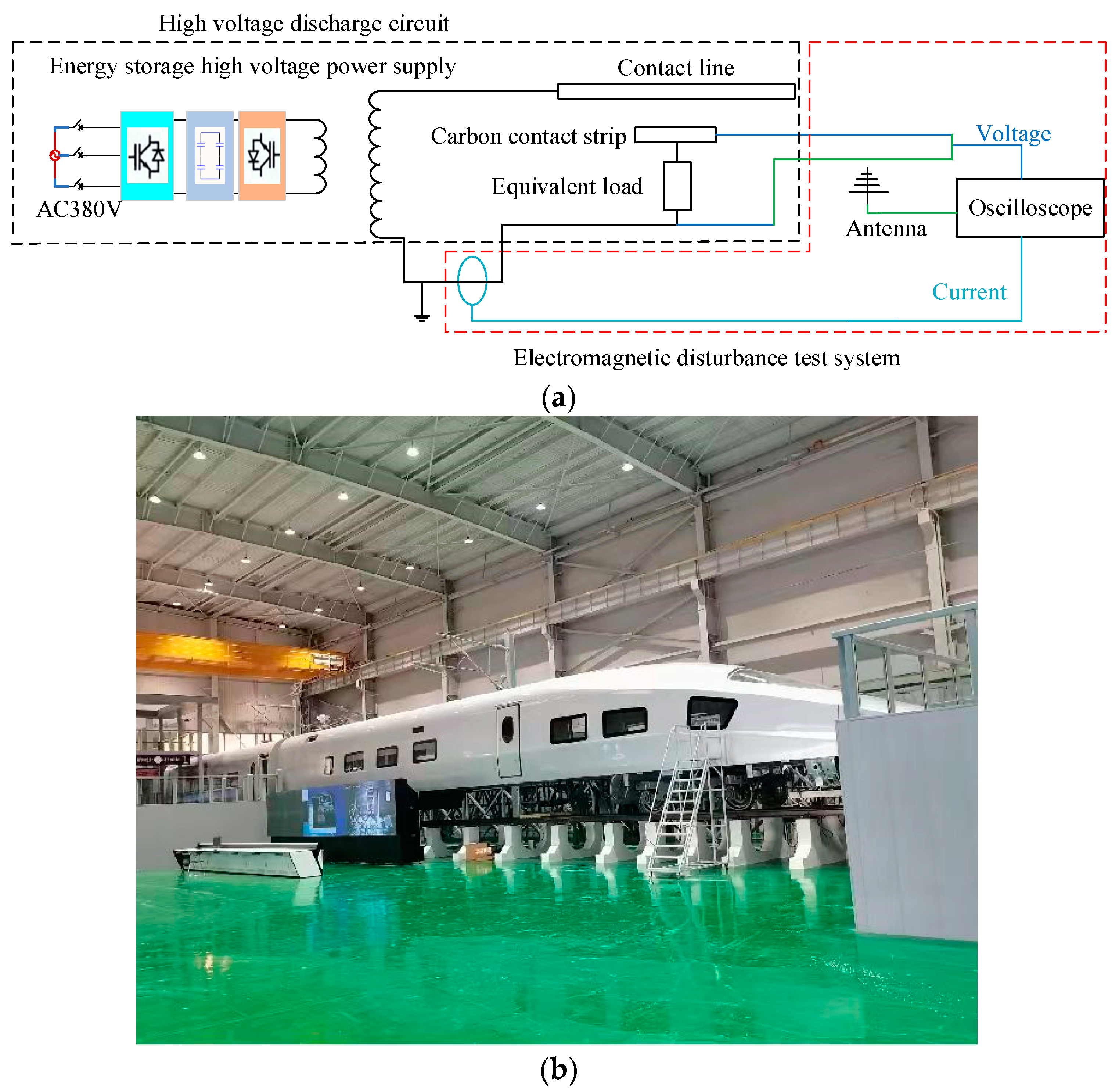
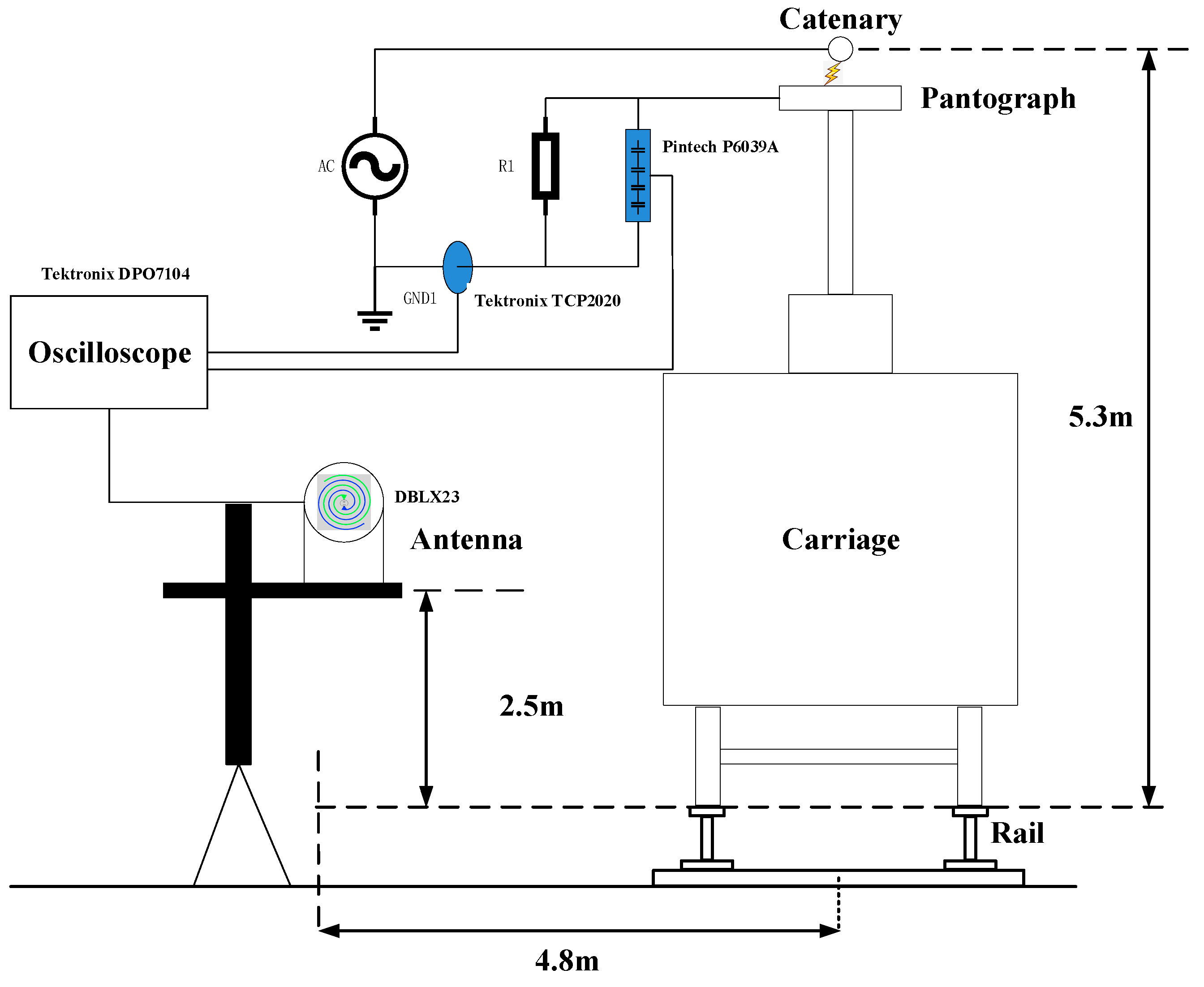
3.1. Experimental Platform Construction

A high-voltage, high-current pantograph–catenary discharge test platform was established, as illustrated in Figure 3. This platform comprises an energy-storage high-voltage power supply, an actual rolling stock train, a contact network pantograph system, and an equivalent load. The high-voltage power supply boasts a capacity of 5.5 MW, capable of supplying short-duration power at a frequency of 50 Hz and a voltage of 27.5 kV. It forms a discharge circuit in conjunction with the contact network, pantograph, and equivalent load. The contact network system maintains a fixed height, with the test allowing for the adjustment of the discharge gap between the contact network and the contact line by controlling the pantograph of the rolling stock. The electromagnetic interference (EMI) testing system comprises an antenna, current and voltage probes, and an oscilloscope. The primary equipment models and parameters of the test platform are outlined in Table 1.

3.2. Test Methodology

During the experiment, the high-voltage probe was connected to both ends of the equivalent load in the high-voltage circuit, with one end serving as the high-voltage terminal and the other as the low-voltage terminal. This configuration was used to measure variations in circuit voltage during discharge. The current probe was positioned along the return line of the high-voltage circuit to monitor the current within the circuit. The vertical polarization of the electric field generated by the pantograph catenary contact loss was measured using a helical antenna, as illustrated in Figure 4. Time-domain measurements of current, voltage, and radiated field were conducted using an oscilloscope, yielding time-domain waveforms for the parameters mentioned above. To analyze the spectrum of electromagnetic interference, the obtained electric field signals were subjected to rapid FFT processing. Throughout the experiment, the ambient temperature was maintained at 27 °C, and humidity was held at 35%.
In practical scenarios, the pantograph catenary contact loss process involves the complete cycle of the pantograph separating from the contact line, then re-establishing contact. The occurrence of high-voltage breakdown and the subsequent zero-crossing reignition phenomenon are specific to certain conditions. To analyze the impact of high-voltage breakdown and zero-crossing reignition on electromagnetic interference, a method involving fixed-gap breakdown discharge between the pantograph and catenary was employed. This method ensures that high-voltage breakdown and arc-current zero crossing for reignition occur in each test.

4. Test Results and Analysis

We adjusted and consistently maintained a 2 mm discharge gap between pantographs while simultaneously adjusting the output voltage of the high-voltage power supply to induce breakdown discharges at various levels (20%, 40%, 60%, and 80% of Umax) across the pantograph gaps. Following this, we synchronously captured the temporal waveforms of voltage, current, and electromagnetic radiation signals. Subsequently, the collected waveform data were analyzed. The high-voltage breakdown discharge phenomenon between the pantograph and the catenary is shown in Figure 5.
The load voltage, circuit current, and electric field spectrum at different voltage levels are shown in Figure 6, Figure 7 and Figure 8, respectively. The peak values of some discharge parameters are provided in Table 2.
The voltage waveforms shown in Figure 6 represent the voltage across the equivalent load terminals. When the power supply voltage is at 20% and 40% of Umax, there are noticeable periods when the voltage waveform approaches zero. This is due to the fact that after the current crosses zero, the arc-gap medium recovers faster than the voltage, causing the arc to extinguish completely, and the insulating characteristics of the pantograph gap recover. The power supply voltage then acts entirely across the pantograph gap. When the instantaneous voltage value continues to rise to the breakdown voltage of the gap, a new arc is generated in the pantograph gap. For power supply voltages at 60% and 80% of Umax, the voltage waveforms resemble sine waves. This is because after the current crosses zero, the voltage across the arc gap recovers faster than the medium, and the arc quickly reignites.
As the output voltage of the power supply increases, the voltage at both ends of the load also increases, the zero-crossing duration decreases, and the distortion in the voltage waveform during the zero-crossing process gradually diminishes. Furthermore, with the rising output voltage, both the 50 Hz steady-state current and the amplitude of transient pulse clusters in the discharge circuit increase. Notably, the electric field strength generated under pantograph–catenary contact loss conditions is also amplified as the output voltage rises. This effect is particularly pronounced near the 125 MHz frequency point, where when the high-voltage power supply output voltage increases from 20% Umax to 80% Umax, the electric field strength near this frequency point increases by approximately 10 dB.
Figure 9 displays the time-domain waveforms of voltage, current, and radiation signals during the pantograph–catenary gap from arc breakdown to stable arc ignition. From the figure, it is evident that under high-voltage, high-current conditions, the pantograph–catenary experiences the highest radiation signal amplitude at the instant of breakdown. During the zero-crossing stages before and after the voltage and current cross zero, a sudden change due to the dynamic equilibrium between dielectric ionization and deionization results in a pulsed current. This phenomenon is accompanied by the generation of electromagnetic radiation.
With a fixed pantograph gap, the waveforms of voltage, current, and electromagnetic radiation at power supply output voltages of 5 kV and 15 kV (peak) are shown in Figure 9. In Figure 9, the voltage, current, and electromagnetic radiation data are normalized and presented as separate subplots, facilitating a comparative display to show the corresponding variations in waveform changes among the three at the same time intervals.
From Figure 9, it can be observed that when the current is relatively low, the zero-crossing time of the arc is longer, the voltage curve exhibits more distortion, and there is a significant pulse current generated during the zero-crossing process, which synchronously triggers a larger electromagnetic radiation signal. As the voltage increases, the arc current also increases. The macroscopic manifestation of the zero-crossing phenomenon becomes less apparent. In contrast to the first breakdown, which generates a large pulse current and significant electromagnetic radiation, subsequent cycles exhibit much smaller pulse currents, reduced voltage waveform distortion, and weakened electromagnetic radiation. This is because with the increase in arc current, the particle concentration within the arc increases, resulting in higher arc energy and increased thermal inertia. Therefore, after the current crosses zero, the presence of a greater number of charged particles in the gap does not lead to the generation of significant pulse currents, unlike the breakdown process.

5. Conclusions

To analyze the electromagnetic interference characteristics resulting from high-voltage gap breakdown discharge and zero-crossing phenomena under high-voltage, high-current conditions, we established a high-voltage discharge electromagnetic interference test system for the pantograph–catenary. We designed a method for conducting fixed-gap breakdown discharge tests on the pantograph–catenary and obtained the following conclusions through experimentation and analysis:
(1)
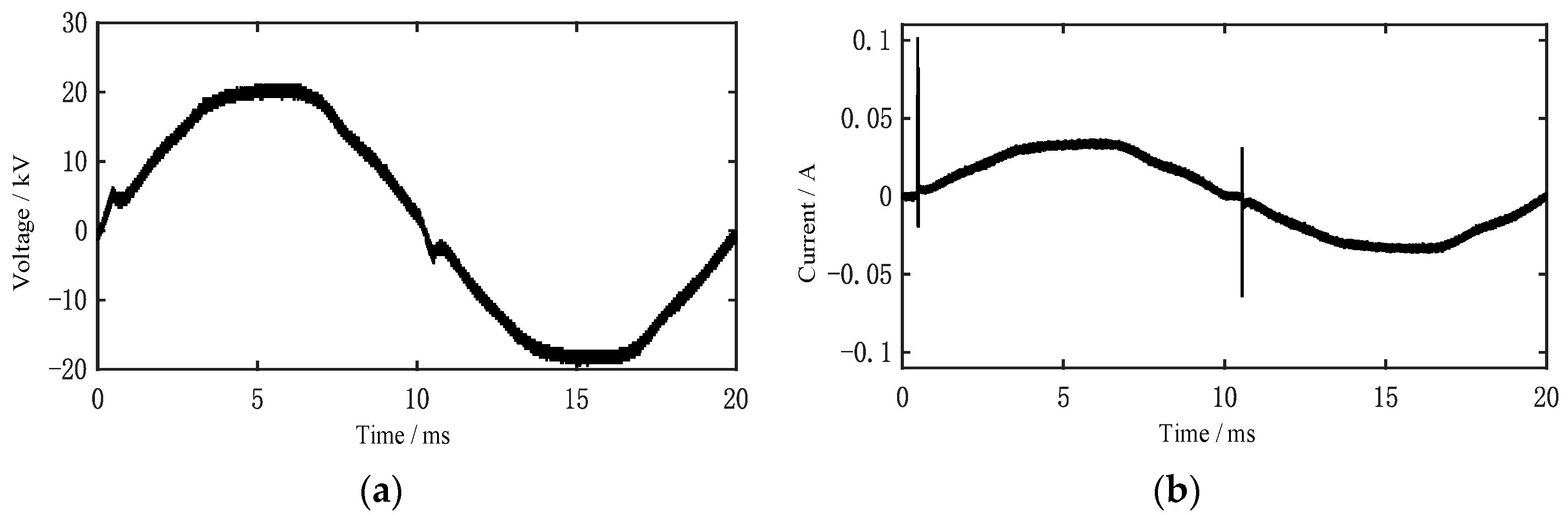
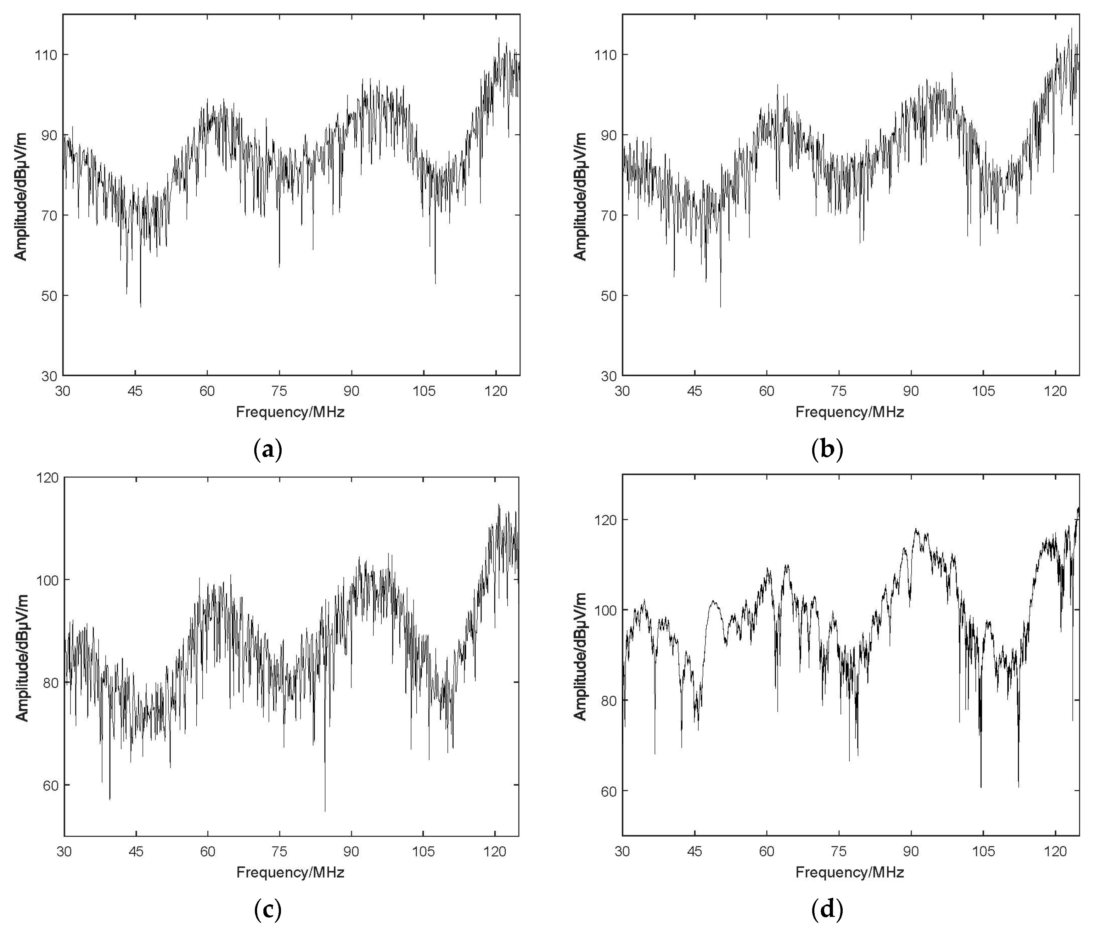
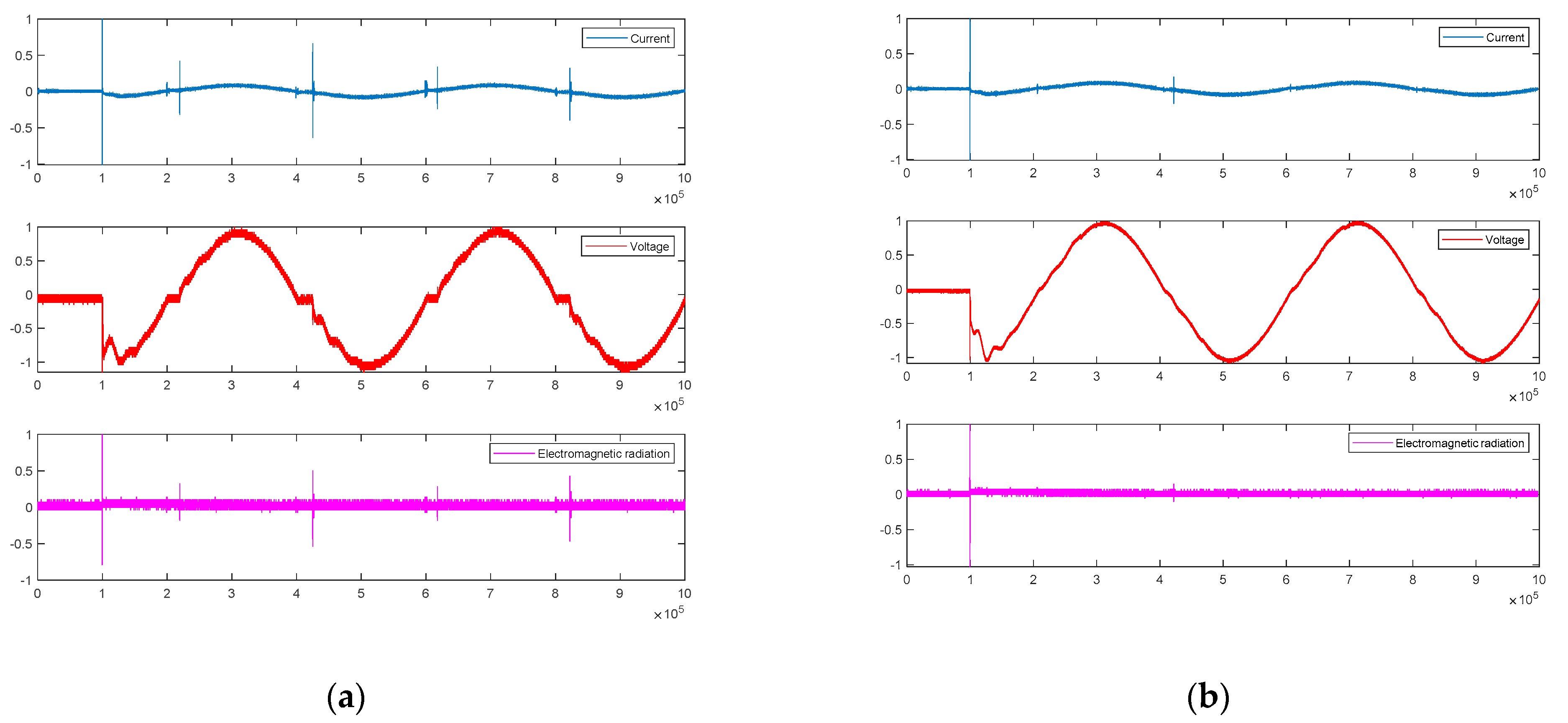
We have, for the first time, identified the distortion in voltage waveforms during the gap breakdown discharge of the pantograph–catenary under high-voltage, high-current conditions. The current waveform comprises a 50 Hz steady-state current and transient pulse clusters, and the electric field spectrum exhibits radiation across the 30 MHz to 125 MHz range, with an overall variation of 60 dBuV/m to 123 dBuV/m.
(2)
With an increase in the power supply voltage, the voltage at both ends of the load also increases, and the extent of distortion in the voltage waveform gradually diminishes. Additionally, the amplitudes of the 50 Hz steady-state current and transient pulse clusters within the discharge circuit are significantly amplified. The radiation intensity generated by the pantograph–catenary discharge increases, particularly in the vicinity of the 125 MHz frequency point. When the output voltage ascends from 20% Umax to 80% Umax, the radiation intensity near this frequency point increases by approximately 10 dB.
(3)
The electromagnetic radiation amplitude is greatest at the instant of the pantograph–catenary gap breakdown. During the stable arc ignition stage of the pantograph–catenary gap, the arc current crosses zero twice per cycle, resulting in the occurrence of zero-current phenomena. Our initial tests confirm that under high-voltage, high-current conditions during the pantograph–catenary discharge arc’s zero-crossing period, pulse currents are generated, accompanied by the emission of substantial electromagnetic interference signals. With the increase in arc current, the zero-crossing time decreases, the number of charged particles in the pantograph catenary gap increases, and the pulse current during the zero-crossing process diminishes, accompanied by reduced electromagnetic radiation. This reveals new characteristics of electromagnetic radiation interference during steady-state arc ignition.

Author Contributions

Conceptualization, Y.Y., S.L. and H.C.; methodology, Y.Y. and H.C.; validation, M.H., M.Z. and Z.S.; formal analysis, M.J., M.Z. and Z.S.; investigation, M.H. and M.J.; writing—original draft preparation, Y.Y., M.Z. and Z.S.; writing—review and editing, S.L., M.H. and M.J.; visualization, M.Z. and Z.S.; supervision, S.L. All authors have read and agreed to the published version of the manuscript.

Funding

This work was supported in part by the National Railway Administration of the People’s Republic of China (grant number N2023G001).

Data Availability Statement

Data are contained within the article.

Conflicts of Interest

Authors Hefei Cao, Mingzhi Zhang, and Zhiguo Su were employed by the company CRSC Research & Design Institute Group Co., Ltd. The remaining authors declare that the research was conducted in the absence of any commercial or financial relationships that could be construed as a potential conflict of interest.

References

  1. Midya, S.; Thottappillil, R. An overview of electromagnetic compatibility challenges in European Rail Traffic Management System. Transp. Res. Part C Emerg. Technol. 2008, 16, 515–534. [Google Scholar] [CrossRef]
  2. Mariscotti, A. Critical review of EMC standards for the measurement of radiated electromagnetic emissions from transit line and rolling stock. Energies 2021, 14, 759. [Google Scholar] [CrossRef]
  3. Seferi, Y.; Blair, S.M.; Mester, C.; Stewart, B.G. A novel arc detection method for dc railway systems. Energies 2021, 14, 444. [Google Scholar] [CrossRef]
  4. Zhang, Y.; Li, C.; Pang, X.; Song, C.; Ni, F.; Zhang, Y. Evolution processes of the tribological properties in pantograph/catenary system affected by dynamic contact force during current-carrying sliding. Wear 2021, 477, 203809. [Google Scholar] [CrossRef]
  5. Yang, H.; Li, C.; Liu, Y.; Fu, L.; Jiang, G.; Cui, X.; Hu, B.; Wang, K. Study on the delamination wear and its influence on the conductivity of the carbon contact strip in pantograph-catenary system under high-speed current-carrying condition. Wear 2021, 477, 203823. [Google Scholar] [CrossRef]
  6. Zhou, H.; Duan, F.; Liu, Z.; Chen, L.; Song, Y.; Zhang, Y. Study on electric spark discharge between pantograph and catenary in electrified railway. IET Electr. Syst. Transp. 2022, 12, 128–142. [Google Scholar] [CrossRef]
  7. Li, M.; Wen, Y.; Sun, X.; Wang, G. Analysis of propagation characteristics of electromagnetic disturbance from the off-line of panto-graph-catenary in high-speed railway viaducts. Chin. J. Electron. 2020, 29, 966–972. [Google Scholar] [CrossRef]
  8. Cai, S.; Li, Y.; Zhu, H.; Wu, X.; Su, D. A novel electromagnetic compatibility evaluation method for receivers working under pulsed signal interference environment. Appl. Sci. 2021, 11, 9454. [Google Scholar] [CrossRef]
  9. Pous, M.; Silva, F. Full-spectrum APD measurement of transient interferences in time domain. IEEE Trans. Electromagn. Compat. 2014, 56, 1352–1360. [Google Scholar] [CrossRef]
  10. Dudoyer, S.; Deniau, V.; Adriano, R.; Slimen, M.N.B.; Rioult, J.J.; Meyniel, B.; Berbineau, M. Study of the susceptibility of the GSM-R communications face to the electromagnetic interferences of the rail environment. IEEE Trans. Electromagn. Compat. 2011, 54, 667–676. [Google Scholar] [CrossRef]
  11. Zhu, F.; Tang, Y.; Gao, C. Mechanism and suppression of electromagnetic interference of pantograph-catenary arc to speed sensor of CRH380BL electric multiple unit. China Railw. Sci. 2016, 37, 69–74. [Google Scholar]
  12. Midya, S.; Bormann, D.; Larsson, A.; Schutte, T.; Thottappillil, R. Understanding pantograph arcing in electrified railways—Influence of various parameters. In Proceedings of the 2008 IEEE International Symposium on Electromagnetic Compatibility, Detroit, MI, USA, 18–22 August 2008; pp. 1–6. [Google Scholar]
  13. Jin, M.; Hu, M.; Li, H.; Yang, Y.; Liu, W.; Fang, Q.; Liu, S. Experimental study on the transient disturbance characteristics and influence factors of pantograph-catenary discharge. Energies 2022, 15, 5959. [Google Scholar] [CrossRef]
  14. Li, X.; Zhu, F.; Lu, H.; Qiu, R.; Tang, Y. Longitudinal propagation characteristic of pantograph arcing electromagnetic emission with high-speed train passing the articulated neutral section. IEEE Trans. Electromagn. Compat. 2018, 61, 319–326. [Google Scholar] [CrossRef]
  15. Song, Y.; Rønnquist, A.; Jiang, T.; Nåvik, P. Railway pantograph-catenary interaction performance in an overlap section: Modelling, validation and analysis. J. Sound Vib. 2023, 548, 117506. [Google Scholar] [CrossRef]
  16. Yao, Y.; Zou, D.; Zhou, N.; Mei, G.; Wang, J.; Zhang, W. Study on the mechanism of vehicle body vibration affecting the dynamic interaction in the pan-tograph-catenary system. Veh. Syst. Dyn. 2021, 59, 1335–1354. [Google Scholar] [CrossRef]
  17. Song, Y.; Wang, Z.; Liu, Z.; Wang, H. A spatial coupling model to study dynamic performance of pantograph-catenary with vehicle-track excitation. Mech. Syst. Signal Process. 2020, 151, 107336. [Google Scholar] [CrossRef]
  18. Van, O.V.; Massat, J.-P.; Laurent, C.; Balmes, E. Introduction of variability into pantograph–catenary dynamic simulations. Veh. Syst. Dyn. 2014, 52, 1254–1269. [Google Scholar] [CrossRef]
  19. Wang, H.; Gao, G.; Deng, L.; Li, X.; Wang, X.; Wang, Q.; Wu, G. Study on Current-Carrying Tribological Characteristics of C-Cu sliding electric contacts under different water content. Coatings 2023, 13, 42. [Google Scholar] [CrossRef]
  20. Tellini, B.; Macucci, M.; Giannetti, R.; Antonacci, G.A. Line-pantograph EMI in railway systems. IEEE Instrum. Meas. Mag. 2001, 4, 10–13. [Google Scholar] [CrossRef]
  21. Tellini, B.; Macucci, M.; Giannetti, R.; Antonacci, G. Conducted and radiated interference measurements in the line-pantograph system. IEEE Trans. Instrum. Meas. 2001, 50, 1661–1664. [Google Scholar] [CrossRef]
  22. Midya, S. Conducted and Radiated Electromagnetic Interference in Modern Electrified Railways with Emphasis on Pantograph Arcing; KTH: Stockholm, Sweden, 2009. [Google Scholar]
  23. Wang, W. Study of Dynamic Characteristic for High Speed Railway Pantograph Arcing; Southwest Jiaotong University: Chengdu, China, 2013. [Google Scholar]
  24. Wu, G.; Wu, J.; Wei, W.; Zhou, Y.; Yang, Z.; Gao, G. Characterization of sliding electrical contact of pantograph-catenary system. High Volt. Engi-Neering 2015, 41, 3635–3641. [Google Scholar]
  25. Gu, Z. Experimental Study on Morphological Characteristics and Plasma Parameters of Pantograph-Catenary Arc; Southwest Jiaotong University: Chengdu, China, 2016. [Google Scholar]
  26. Gao, G.; Yan, X.; Yang, Z.; Wei, W.; Hu, Y.; Wu, G. Pantograph-catenary arcing detection based on electromagnetic radiation. IEEE Trans. Electromagn. Compat. 2018, 61, 983–989. [Google Scholar] [CrossRef]
  27. Gao, G.; Yan, X.; Wei, W.; Hu, Y. Electromagnetic radiation of pantograph-catenary arc based on Hilbert fractal antenna. High Volt. Eng. 2019, 45, 324–329. [Google Scholar]
  28. Guo, F.; Wang, X.; Wang, Z.; Wang, D.; Wang, B. Experimental research on total harmonic distortion of contact current caused by panto-graph-catenary off-line. Trans. China Electrotech. Soc. 2015, 30, 261–266. [Google Scholar]
  29. Guo, F.; Wang, X.; Wang, Z.; Zhang, Y.; Wang, B. Research on radiated electric field noise of pantograph arc. Trans. China Electro-Tech. Soc. 2015, 30, 220–225. [Google Scholar]
  30. Gortschakow, S.; Franke, S.; Methling, R.; Gonzalez, D.; Lawall, A.; Taylor, E.D.; Graskowski, F. Properties of vacuum arcs generated by switching RMF contacts at different ignition positions. Energies 2020, 13, 5596. [Google Scholar] [CrossRef]
Figure 1. Typical arc voltage and current waveforms under resistive loads.
Energies 17 00138 g001
Figure 2. Typical voltage and current waveforms of high-voltage, the small-current breakdown discharge process. (a) Voltage waveform; (b) current waveform.
Energies 17 00138 g002
Figure 3. Schematic diagram of the test platform. (a) Schematic diagram of the equivalent principle of the test platform; (b) overview of the test platform.
Energies 17 00138 g003
Figure 4. Layout diagram of the test setup.
Energies 17 00138 g004
Figure 5. Breakdown discharge phenomenon between the pantograph and catenary.
Energies 17 00138 g005
Figure 6. Load voltage at different output voltage levels. (a) 20% Umax; (b) 40% Umax; (c) 60% Umax; (d) 80% Umax.
Energies 17 00138 g006
Figure 7. Circuit current at different output voltage levels. (a) 20% Umax; (b) 40% Umax; (c) 60% Umax; (d) 80% Umax.
Energies 17 00138 g007
Figure 8. Electric field spectrum at different output voltage levels. (a) 20% Umax; (b) 40% Umax; (c) 60% Umax; (d) 80% Umax.
Energies 17 00138 g008
Figure 9. Synchronously sampled waveforms of voltage, current, and electromagnetic radiation signals. (a) Waveform of breakdown discharge at 5 kV; (b) waveform of breakdown discharge at 15 kV.
Energies 17 00138 g009
Table 1. Main equipment list.
No.DesignationModel NumberMain Parameters
1AC high-voltage generator Frequency, 50 Hz; maximum output voltage, 50 kV; rated capacity, 5 kVA
2Contact wireCT85Resistivity, 0.0177 Ω∙mm2∙m−1
3Carbon contact stripJL-14Resistivity, 13 Ω∙mm2∙m−1
4Current-limiting resistor High-voltage non-inductive resistance, 560 kΩ
5OscilloscopeTektronix DPO7104Bandwidth, 1 GHz
Maximum sampling rate, 40 GS/s
6Helical antenna DBLX23Frequency response range, 30 MHz–2 GHz
7Voltage probesPintech P6039ABandwidth, 220 MHz; maximum test voltage, AC 1–28 kV (50/60 Hz)
8Current probesTektronix TCP2020Bandwidth, 50 MHz; high current: 20 A RMS
Pulse current, 100 A peak; rise time: <7 ns
Table 2. The peak values of certain discharge parameters.
Voltage Level20% Umax40% Umax60% Umax80% Umax
Peak of Discharge Parameter
Load Voltage (kV)3.424.1510.1817.65
Electric Field for 125 MHz (dBμV/m)111.3112.5114.8122.8
Disclaimer/Publisher’s Note: The statements, opinions and data contained in all publications are solely those of the individual author(s) and contributor(s) and not of MDPI and/or the editor(s). MDPI and/or the editor(s) disclaim responsibility for any injury to people or property resulting from any ideas, methods, instructions or products referred to in the content.

