Article

Energy Management in a Standalone Microgrid: A Split-Horizon Dual-Stage Dispatch Strategy

1
Department of Electrical Engineering, United Arab Emirates University, Al Ain P.O. Box 15551, United Arab Emirates
2
National Water and Energy Center, United Arab Emirates University, Al Ain P.O. Box 15551, United Arab Emirates
*
Author to whom correspondence should be addressed.
Energies 2023, 16(8), 3400; https://doi.org/10.3390/en16083400
Submission received: 23 March 2023 / Revised: 6 April 2023 / Accepted: 10 April 2023 / Published: 12 April 2023
(This article belongs to the Special Issue Energy Management of Smart Grids with Renewable Energy Resource)

Abstract

:
Microgrid technology has recently gained global attention over increasing demands for the inclusion of renewable energy resources in power grids, requiring constant research and development in aspects such as control, protection, reliability, and management. With an ever-increasing scope for maximizing renewable energy output, there is also a need to reduce the curtailment of power on both the generation and demand sides by increasing forecasting accuracies and using resources more effectively. This paper proposes a dual-stage dispatch employing a novel “split-horizon” strategy, in a bid to enhance energy management in a standalone microgrid. The split-horizon is essentially the considered time horizon split into equal operational periods of the dual-stage dispatch. The proposed strategy utilizes a custom-designed novel variant of the inertia-weight-based particle swarm optimization (PSO), termed customized PSO, to perform the optimal schedule and dispatch operation by benefitting from the simplicity of PSO and customization as per the considered objectives. A modified IEEE 34-node test system is derived into a standalone microgrid with added distributed energy resources to test the proposed strategy, while another standalone microgrid, a modified IEEE 69-node test feeder, is also considered for scalability. Furthermore, the validation of the strategy is performed appropriately with a case study while also validating the proposed optimization algorithm. It is observed that the proposed energy management strategy provides approximatelya 7% reduction in costs.

1. Introduction

The increase in electrical energy needs worldwide requires a steady growth in power generation. This further requires the development of related infrastructure, equipment, and innovative technology. This is coupled with the need to increase the generation capacities of renewable energy resources (RE). As a solution, the concept of microgrid (MG) surfaced among service providers as a viable localized RE enabler along with energy storage systems (ESS). Viewed as a single entity, an MG can function in isolation, with the grid or with a system of MGs. An MG may consist of distributed energy resources (DER) including low-power conventional sources, power conversion interfaces such asinverters, protection equipment, necessary control, and monitoring equipment [1]. An essential element is the energy management system (EMS) that performs decisions concerning the power flow in an MG.
An EMS in an MG provides optimal solutions for the power-balancing required while considering objective functions formulated with constraints, such as voltage and frequency regulation, necessary forecasting and monitoring of electricity market prices, weather data, etc. [2,3,4]. There are a number of EMS strategies from the recent past that resonate well with the growing RE availability, providing optimal power-sharing solutions among the DER. Accordingly, researchers classify them based on necessary factors in an EMS, such as power schedule, optimization methodology, control methodology, elements in the MG network, etc. [3]. In one classification, authors in [5,6] proposed “offline” optimal power scheduling where forecasted data were used for the purpose. However, the method does not facilitate the validation of the strategies on real-time power dispatches. Under the same classification, authors in [7,8,9,10,11,12] proposed strategies that provide “online” optimal power scheduling in two stages. The second stage includes the generation of dispatch set points using real-time data.
Zhu et al. [7] formulated a two-layer coordinated EMS strategy aimed at providing close to real power dispatch values. The method, however, involves some ambiguity concerning the coordination of the two layers, which is cleared in the work by Jiang et al. [8] while correcting the RE energy intermittence with power reserves during scheduling. Both these works used the look-ahead optimization method while aiming to achieve coordinated power scheduling. Many researchers have based their strategies on well-established control techniques, such as Model Predictive Control (MPC), with a similar aim. References [9,10,11,12] have used MPC, which corrects possible errors in a pre-generated schedule of optimal output close to a real-time schedule, to coordinate between the two stages of power dispatch. Among them, Sachs and Sawodny [9] presented an MPC-based two-level EMS strategy for a standalone one-bus MG. Taha et al. [10] presented a similar two-stage EMS for a grid-connected MG aiming to minimize total operating cost and minimize pollutant emission. Moretti et al. [11] presented a two-layer predictive dispatch strategy for an off-grid MG with a single bus. In a more practical sense, Solanki et al. [12] proposed a two-stage EMS based on a unit commitment (UC) and three-phase unbalanced Optimal Power Flow (OPF).
In [13,14,15,16,17,18], researchers managed the power flow through strategic use of MG elements such as the ESS. Among them, Almada et al. [13] proposed a heuristic EMS strategy for an MG in grid-connected and isolated conditions, where the Battery ESS (BSS) is used as a voltage reference for other MG elements in a master–slave configuration. In a similar rule-based EMS setup, Belila et al. [14] presented two different control scenarios for a standalone MG, where the state of charge (SoC) of the BSS is used strategically to move between the scenarios. Under the same class, Chalise et al. [15] proposed a strategy for a remote MG considering the lifetime of the BSS in the form of its degradation cost, while Gao et al. [16] strategized a very similar objective for a grid-connected MG. In a relatively different work, Sukumar et al. [17] presented a strategy for a grid-connected MG to select the most optimal cost-providing “mode”, from among three modes having different objective functions. In this study, particle swarm optimization (PSO) is used to determine optimal battery sizing. With a different aim, Moradi et al. [18] proposed a strategy comparing the cost minimization under both the presence and absence of ESS in the network with a distribution function-based RE and demand forecast, while references [19,20,21] include demand response (DR) options and use some innovative EMS strategies.
A common goal among the above strategies is optimizing a set of objective functions along with necessary constraints. The above references either use one of the Linear Programming (LP) variants for the formulated linear/non-linear objective functions, or heuristic algorithms/intelligent algorithms and their variants [2,22,23]. The intelligent algorithms, however, provide quicker results, although with occasional errors, such as a local minima solution. Thus, there are many developments in the intelligent algorithms’ realm, adding to the fact that no such algorithm can solve all problems [24], suggesting the possibility of customizing existing techniques as per the problem at hand. Likewise, another important aspect of an EMS strategy is the utilization of accurate and precise forecasting techniques to predict RE availability and load demand. However, the generated forecasts have significant levels of mean error, causing a mismatch between the energy dispatch and its schedule, in spite of reserving a considerable amount of power, prompting the use of Intra-Day (ID) Scheduling [8,15]. Although such solutions help overcome forecast errors, errors cause reliability issues in the power network, thus requiringmore focus on reducing their effect [25,26,27].
Researchers and professionals alike have provided extensive analysis of RE forecast methodologies, spatial and temporal variability, and their efficiencies concerning all the viable forecast horizons (hour, day, week, or year) [28]. Likewise, plenty of literatures show the effect of different forecasting models (statistical, physical, NWP-based, etc.) with respect to varying forecast horizons and time steps. In support of this, Orwig et al. [26] presented the effect of forecasting wind power for a shorter horizon spanning 0–6h ahead of power dispatch instead of the traditional day-ahead (DA) forecast. On analysis, the 6-h forecast showed significant closeness to the original data than the DA forecast, while also proving more economical. In [27], similar research concerning solar forecasting provided a comparative analysis of accuracies between DA forecasts and one-hour forecasts for the same duration, where the data from the latter provided better accuracy than the former based on certain evaluation metrics selected in the study. Thus, the observations highlight that the forecast horizon directly affects the accuracy of any forecasting model or technique, suggesting that the shorter the forecast horizon, the better the accuracy [29].
The briefing from the literature provides a few insights into the developments in the area of EMS of an MG system, the concerned optimization techniques, and the forecast efficiencies of RE and load demand in a system, with certain limitations or unfavorable scenarios in many of them. Scenarios such as load shedding, RE curtailment, and low RE penetration and utilization provide scope for improvement in forecast efficiencies, and thus, the power reserve planning. This paper proposes a dual-stage dispatch employing a “split-horizon” strategy by splitting a 24-h time horizon strategically. The strategy is presented on an MG simulated by a modified IEEE 34-node and a modified IEEE 69-node test system that provides network constraints along with other energy flow-related constraints in the network. Additionally, the proposed strategy is brought to fruition with a second objective: a novel variant of the PSO, termed Customized PSO (C-PSO), which serves as a better optimization for the considered dual-stage dispatch problem. The outlined objectives thus provide the following as contributions:
  • A novel “split-horizon” strategy for the dual-stage dispatch problem in a standalone microgrid, realized by “splitting” the 24-h time horizon into four 6-h quarters with the aim to facilitate more accurate forecasts for the entire time horizon; this enables better utilization of existing forecasting techniques on shorter periods of the total forecast horizon.
  • A novel variant of the inertia-weight based PSO providing improved optimization with respect to the standard versions: enhancing exploration capability of individual particles to increase search space usage, as well as avoiding solutions falling into local minima; customized to handle the mixed-integer type dual-stage dispatch problem, hence the name “customized PSO”.
The above objectives together provide a common outcome as part of the simulation, while their validity is explored with suitable analysis. This paper is presented in five sections, where Section 2 presents the details ofthe system model and parameters along with the required tools, Section 3 provides details on the EMS strategy, Section 4 explains the results from the simulation, and Section 5 concludes the proposed work.

2. System Modeling and Required Tools

2.1. Microgrid Network

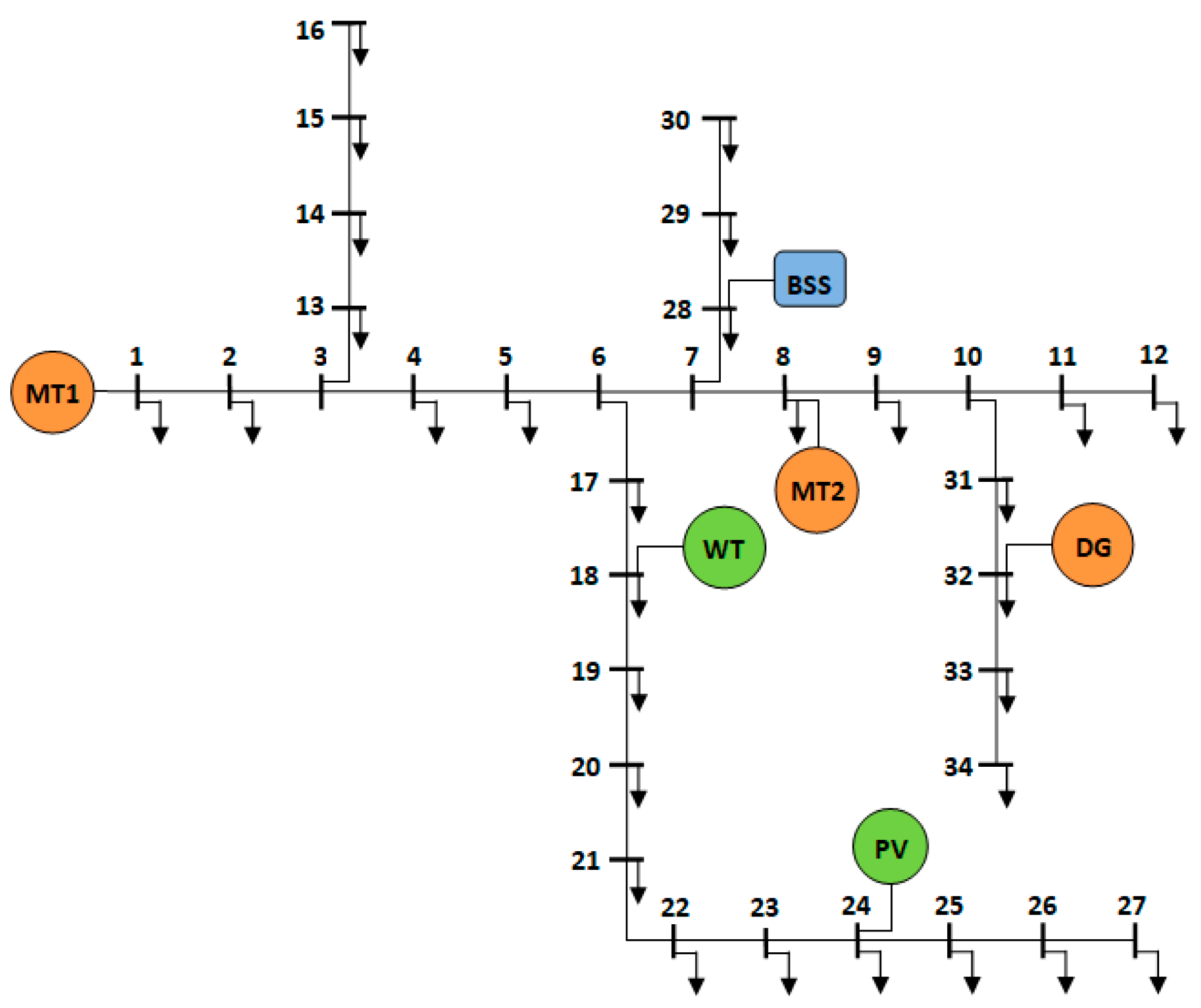
The MG network, as shown in Figure 1, is a modified IEEE 34-node test system [30] with DERs, while a secondary MG network is presented in ‘Section 4’ (modified IEEE 69-node test feeder). The 34-bus network consists of the main feeder (buses 1 through to 12) and four lateral sub=- feeders with a base voltage of 11 kV and base power of 12 MVA. The loads represent lumped loads for the ease of performing load flow analysis to obtain the voltage levels of each bus and the net power loss in the system. It is assumed that the lumped loads are present at all buses, except for the junction buses where the lateral feeders are connected.
The dispatchable sources considered in this network include two gas-fueled MT (MT1 and MT2) with a rated power of 2.6 MW and 1.4 MW, respectively, and a 500 kW DG. The RE sources include a 2 MWp PV and a 3.5 MW WT along with a 4 MWh BSS. The total power level adds up to 4.5 MW of dispatchable power and approximately4–5.5 MW of usable power from RE sources. The placement of the sources is decided such that the voltage levels at all the buses are relatively close to each other and within set voltage limits. Additionally, all the buses in the network are designed to be PQ buses, except the generation buses and the slack bus.

2.2. PV Generator Model

The PV generator is located at a single site in the network. The system power-generation model utilizes the forecasted and the real-time solar irradiance data, presented as [31]:
P P V t = η P V N A P V G ( t )
where ‘PPV’, ‘ηPV’, ‘APV’, ‘N’ and ‘G’ are the power level of the PV arrays (kW), efficiency of power production (including the inverter efficiency), the total area covered (m2), the total number of PV modules and the solar irradiance (W/m2), respectively. ‘G’ is either the Global Horizontal Irradiance (GHI) or Global Tilted Irradiance (GTI) if the panels are tilted. The peak wattage is decided such that the total available RE on average can cover at least up to half the total connected load, which is considered approximately10 MVA. Thus, the number of arrays and the area covered by them are also assumed accordingly.

2.3. Wind Energy Generator Model

The wind turbine (WT) is generally modeled such that the power generated is dependent on the wind speed, which can be modeled using the Weibul Probability Distribution Function. In this work, the wind speed is obtained based on shapes and variations of real-time wind profiles. The real power generated by wind generator can be expressed as [32]:
P W T t = 0 , v < v i   a n d   v > v o P W T r ( v v i ) ( v r v i ) , v i v v r P W T r , v r v v o
where ‘PWT’, ‘PWTr’, ‘vi’, ‘vo’ and, ‘vr’ are the power generated by the WT, its rated power, the cut-in, cut-out and rated speed of the wind, respectively. Here the rated power of the WT is assumed approximately 3.5 MW.

2.4. Microturbine Model

The micro turbine (MT) isselectedas the major generating source in this work. Single MT units have capacities ranging from tens of kW to a few hundreds. They run on gas or fuel, such as diesel, and thus, tend to have low fuel efficiency at less than rated power levels. In order to use MTs with higher power levels, manufacturers cascade multiple units of similar characteristics with a rated power equivalent to the sum of the powers from the single units. This characteristic of MTs allows them to function with “part-load” efficiencies, where a cascaded unit could function at maximum fuel efficiency even at lower power levels. The part-load condition is obtained either by keeping the power level of individual units in the cascade low or by turning the unnecessary units ‘OFF’. The model of the MT is represented using its fuel consumption curve as:
F M T = β P M T + γ
where ‘FMT’ and ‘PMT’ are the amount of natural gas consumed and the power generated by the MT, while ‘β’ and ‘γ’ are the gas consumption coefficients (units of L/kW/h and L/h, respectively) that are obtained empirically using the C1000S Capstone Microturbine technical reference [33]. The fuel cost curve is obtained by multiplying the expression with the AED/L cost of natural gas.

2.5. Diesel Engine Generator Model

The diesel generator (DG) is used as a generator that could function as a peaking or a backup generator. The function is attributed to the fact that the efficiency of the DG is low compared to other generators, and hence, it needs to function as close to the rated power as possible. Another factor concerning its operation is the fuel in use (diesel) that has a relatively high fuel cost [34]. The model representing the DG is its fuel consumption characteristic presented as:
F D G = α P D G 2 + β P D G + γ
where ‘FDG’ and ‘PDG’ are the fuel consumed and the power generated by the DG, while ‘α’, ‘β’ and, ‘γ’ are the fuel consumption coefficients (units of L/kW2/h, L/kW/h, and L/h, respectively) derived from the datasheet of a 500 kW Generac®DG. The fuel cost curve is obtained by multiplying the expression with the cost of diesel.

2.6. BSS Model

The battery energy storage system (BSS) is considered as a bidirectional source, which acts as a source while discharging, as load while charging, and idle otherwise. The model representing the BSS is expressed in terms of the energy charged or discharged with respect to its maximum capacity and SoC of the BSS as [10]:
E ( t ) = T η c P B S S p ( t ) P B S S n ( t ) η d
S o C ( t + 1 ) = S o C ( t ) + 100 × E ( t ) E c %
where ‘E’, ‘PBSSp’, ‘PBSSn’, ‘ηc’, ‘ηd’, ‘ΔT’, and ‘Ec’ are the energy level of the BSS at time ‘t’, power during charging state, power during discharging state, charging efficiency, discharging efficiency, duration of charge or discharge, and the maximum storage capacity of the BSS, respectively.

2.7. Backward/Forward Sweep Method

Power flow analysis of a network is performed typically using the Newton–Raphson method or fast-decoupled method, owing to their good convergence characteristics during iterations [35]. However, an anomaly is the non-convergences that occur while analyzing radial networks, such as distribution feeder lines, the reason being the high line resistance to reactance ratio in distribution lines [36]. In such a scenario, the simpler Backward/Forward Sweep (BFS) method is utilized since it only requires the calculation of the relevant bus voltages and branch currents using Kirchoff’s Voltage and Current laws (KVL and KCL) iteratively [36].
The network here is adopted from a distribution test feeder network, which prompts the usage of the BFS method. The algorithm includes two phases: the Backward Sweep and the Forward Sweep. The Backward Sweep, as the name suggests, calculates the branch currents from the terminal nodes of a network through to the reference node. The Forward Sweep on the other hand calculates the bus voltages in the opposite direction. These methods are used in succession with the initial assumption that the voltages at all the buses are equal to voltage at the reference node, which is 1 p.u. The evaluations of the sweep methods are carried out in a loop until the bus voltages calculated in successive iterations are within a specified tolerance level.
The equations involved in the Backward Sweep method include the current calculation of individual branches using KCL from individual buses as:
I k 1 , k = I b u s k + P j Q 3 × c o n j ( V ( k ) ) + I p r e
where ‘k1’ and ‘k’ are the sending and receiving nodes of the branches, ‘Ibus(k)’, ‘P’, ‘Q’ and ‘V’ are the bus current, real power, reactive power, and the bus voltage at the receiving node ‘k’, respectively. Here, ‘Ipre’ is the current of the preceding branch from the same feeder. Similarly, the equations used in the Forward Sweep method include the voltage calculation of individual buses using KVL as:
V a = V c + Z I ( c , a )
where ‘a’, ‘c’, ‘Z’, and ‘I(c,a)’ are the receiving node, the sending node, the impedance and the corresponding current in the branch between nodes ‘a’ and ‘c’, respectively. Additionally, the power losses can be calculated as:
P l o s s = I k 1 , k 2 R ( k 1 , k )
where ‘Ploss’ is the total power loss in the network calculated here as the sum of the resistive drops across all branches, while ‘k’ and ‘k1’ are sending and receiving nodes and ‘R’ is the resistance between them.

2.8. Proposed Customized Particle Swarm Optimization

In 1995, James Kennedy and Russell Eberhart devised the PSO algorithm for unconstrained single-objective optimization problems inspired by the food searching mechanism of flocks of birds [37]. The algorithm programs individual variables called ‘particles’ (analogous to birds) to search a specified search space for the optimal solution of a problem. The velocity and position update equations in the standard PSO are presented as [38]:
V p t + 1 = w · V p t + c 1 · r 1 · X p t P b e s t p + c 2 · r 2 · X p t G b e s t
X p t + 1 = X p t + V p t + 1
where ‘Xp’, ‘Vp’, ‘w’, ‘c1’, ‘c2’, ‘r1’, ‘r2’, ‘Pbestp’, and ‘Gbest’ are the position and velocity of a particle ‘p’, the inertia weight, acceleration coefficients, random numbers, local best position of ‘p’, and the global best position, respectively. Additional terms include maximum iteration number and number of decision variables.
The algorithm, with an inertia weight-based variant (standard PSO henceforth), has intricate issues related to exploration and exploitation phases causing premature convergence for a variety of reasons [39]. Many variants of the standard PSO provide marginal improvement in its abilities, but with increased number of tuning parameters and/or complexities. The proposed split-horizon dual-stage dispatch strategy requires an optimization technique suitable to perform mixed-integer type problems for both UC and ED, generally complex for swarm-type intelligence algorithms. The proposed algorithm, C-PSO, is simply the standard PSO ‘customized’ to be application specific. Although it involves very simple changes in the core algorithm of the standard version, the convergence is faster with significant improvement in the ability to fall out of local optima. The novelty was achieved empirically with the aim of avoiding premature convergence in this work, otherwise observed while using the standard PSO. Considering the same optimization parameters as those in the standard version, the C-PSO includes two amendments to accommodate the customization as follows:
  • A dedicated exploration time for each particle, to find the best individual fitness prior to exchanging information with other particles.
  • The particle providing the best fitness (Gbest), after saving the Gbest position and fitness value, is “relocated” to another position prior to the velocity update, thus updating the position vector twice.
The first point above requires a variation in the previously presented velocity update in Equation (10) as:
F o r t w 1 × m a x I t e r , V p t + 1 = w · V p t + c 1 · r 1 · X p t P b e s t p
where ‘w1’ is an empirically fixed fraction of the maximum iteration number. In this equation, the velocity is updated only with respect to Pbest of the particles suggesting that C-PSO allows particles to explore the search space ‘independently’ under the given condition. For the rest of the iterations, it allows them to exploit the search space ‘dependently’ using Equation (10) for velocity update. The second point is executed by ‘relocating’ the particle position for the particle that provides the Gbest using the following expression:
X p t = X p t ( 1 0.1 × r a n d )
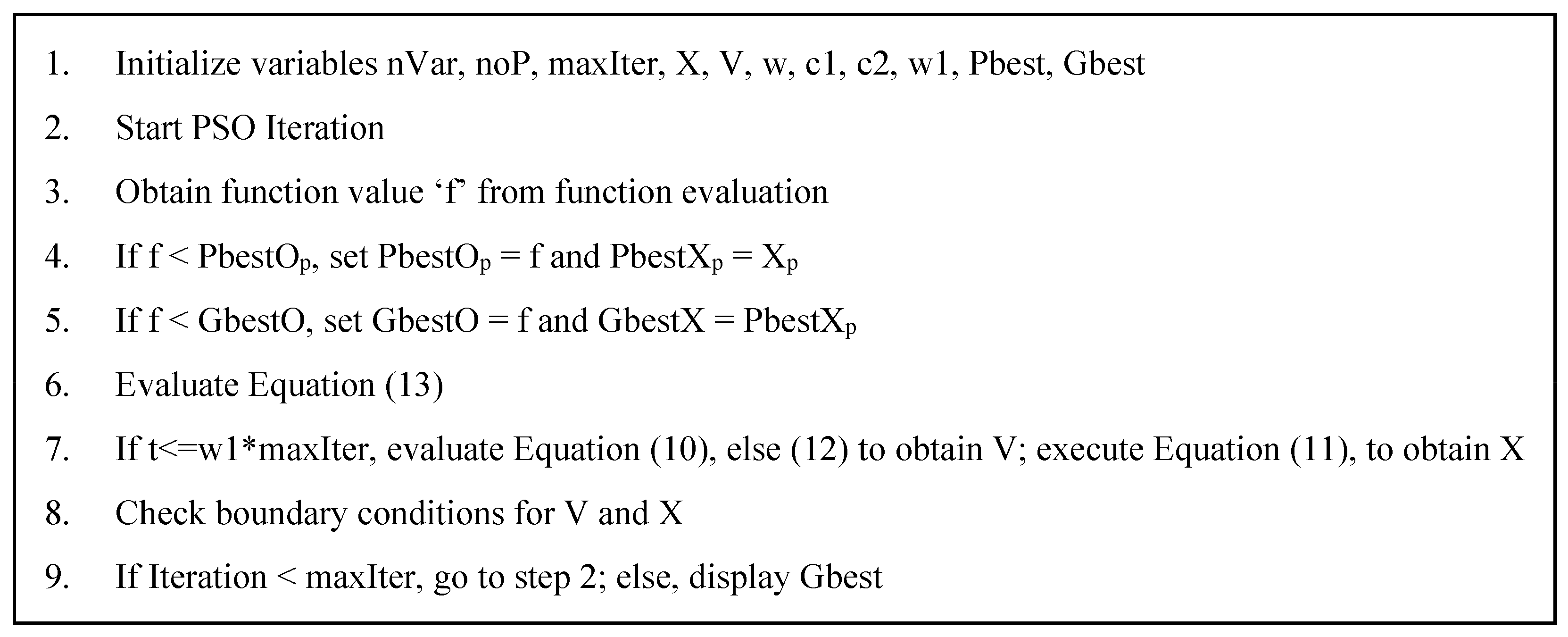
The above expression allows the concerned particle to be randomly relocated in a closer proximity to its previous location enabling it to actively participate in the search space. The pseudo code in Figure 2 shows the functioning of the C-PSO technique, which is very similar to the standard PSO, except for the above-mentioned variations.
To validate C-PSO, three other optimizers, including PSO, Butterfly Optimization Algorithm (BOA), and Coot Optimization Algorithm (COA), are utilized, where BOA is relatively new and simple while COA is one among the latest optimizers, thus making an apt set of optimizers for comparison. BOA is an optimizer that functions based on the food searching and socializing ability of butterfly swarms. Its algorithm involves mathematical expressions considering the “fragrance” sensing ability of butterflies along with their random movements in a search space [40]. COA, on the other hand, is conceptualized based on the food searching ability of a bird species called Coot, where the algorithm includes mathematical expressions to include their “leader-followers” based search mechanism [41].
The common parameters among the four optimizers are the number of runs, population size, and the maximum number of iterations, which are set at 50, 50, and 500, respectively. Among the algorithm-specific parameters, the parameters c1, c2, and w1 in PSO and C-PSO are given values 2, 2, and 0.2, respectively, while the BOA parameters probability switch (p) and power exponent (a) are given values 0.8 and 0.1, respectively, along with an iteratively varying parameter, sensory modality (c), initially set at 0.9.
The optimizers execute approximately 10 benchmark functions including “unimodal”, as well as “multimodal” functions as depicted in Appendix A. Each of the functions is given a certain dimension number, unless specified in the function, to have considerable complexity, while each has its own stipulated search space and known optimal solution, thus providing a means to compare different optimizers. The metrics used in the comparison include root mean square error (RMSE), best value, worst value, and standard deviation (SD), the descriptions for which are provided in [40]. The results from the optimization are presented in Table 1, showing the dominance of C-PSO over the rest of the considered optimizers in all the metrics in all functions.

3. Proposed Split-Horizon Dual-Stage Dispatch Strategy

The proposed strategy is essentially novel for an MG EMS hitting two targets with a single strike, including an optimal scheduling, as well as an economic dispatch of power. Split-Horizon, which is the “splitting” of the total time horizon into smaller periods, serves the purpose of reducing the error in forecasting the RE availability and the load demand irrespective of the utilized forecast technique. In this research work, the splitting is based on the availability of solar energy, which usually can be split into four domains or “quarters”: pre-dawn (0–6), dawn to noon (6–12), noon to dusk (12–18) and post-dusk (18–24), each spanning approximately6 h. Using solar energy availability simply provides an apt number of split-horizons where the solar energy level in each quarter would be similar every day. The considered dual-stage dispatch problem comprises the generic power scheduling concepts of unit commitment (UC) and economic dispatch (ED), albeit the additional power scheduling in the first stage is selected as a reference for the second stage. Thus, each quarter is dual-staged, where the first stage is executed at once, while the second stage is executed at every time step.

3.1. Quarter-Day Ahead Schedule

The first stage consists of the UC and scheduling of power levels among the dispatchable generators, whose power levels can be controlled. Thus, using the forecasted values of the RE sources and load demand, an optimal dispatch is obtained. The objective function in the first stage is a cost minimization problem, consisting of a starting cost, operation and maintenance cost, and fuel cost based on its consumption and efficiency as shown in the following expression:
F S C = t = T s t = T e g G u a g P g 2 t + b g P g t + c g + O M g P g t U g ( t ) T + S U g U g c + ( c s n P B S S n t c s p ( t ) + O M B S S | P B S S t | ) T + c C o n k c p c 2
The schedule cost function FSC is calculated from start-time ‘Ts’ to end-time ‘Te’ of each quarter. The time step ‘ΔT’ is set as 5 min to closely follow the availability of the RE sources. The coefficients ‘ag’ (AED/kW2 h), ‘bg’ (AED/kWh) and, ‘cg’ (AED/h) form the quadratic fuel-cost function for each dispatchable unit ‘g’ with power level ‘Pg’, while ‘OMg’ is the cost coefficient for the operation and maintenance of unit ‘g’. The terms ‘SUg’ and ‘Ugc’ are the start-up cost and the variable denoting the ON-state of the unit ‘g’, while ‘Ug’ denotes the control state (0 or 1) of the unit ‘g’, used to select its generation cost. Similarly, the costs related to the BSS include ‘csn’, ‘PBSSn’, ‘OMBSS’, and ‘PBSS’ which are the cost for discharging the BSS, its discharge power level, the operation and maintenance costs and the power level during charge/discharge stage, respectively. The cost for charging the BSS, ‘csp(t)’ can be expressed as:
c s p = a i P B S S p 2 t + b i P B S S p t + c i + O M i P B S S p t T
where ‘i’ is the generator unit that was turned ‘ON’ the latest. It is to be noted that the BSS is charged by the DERs in the network and hence ‘csp(t)’ in Equation (15) is a quadratic cost function that represents the cost of charging the BSS from the DER unit ‘i’ charging it, thus incurring a negative factor in Equation (14). For optimization ease, the BSS is expected to incur cost during discharge while the charging stage incurs only the operation and maintenance cost. The last term in Equation (14) is the sum of the total penalties in the optimization problem relating relevant constraints expected to close out to zero, where ‘kc’ is the penalty factor, ‘pc’ is the penalty function and ‘Con’ is the number of constraints described in the problem.
One of the most important optimization constraints in a dispatch problem is the power balance equation, where the total demand in the system (including the demand from the BSS) and the consequent network losses are met by all the generators collectively. In mathematical terms,
l L D P l + P l o s s = g G u U g P g + P P V + P W T + U B S S P B S S
where ‘Pl’, ‘Ploss’, ‘PPV’, and ‘PWT’ are the sum of the total power demand, power loss in the network, power generated from the PV array, and power supplied from the wind energy conversion system (WT), respectively, for the time instant ‘t’, while the term ‘UBSS’ denotes the control state (−1, 0 or 1) of the BSS. The above equation is subject to a constraint that reserves a certain amount of power in the system. ‘PRes’ corresponds to the power reservation constant that is considered only during scheduling to correct discrepancies in forecasting. Since the proposed strategy deals with a relatively reduced level of forecast error by virtue of reduced forecast lead-time, the possibility of having a fixed and yet reasonable amount of reserve power is expressedwith the following Equation [8]:
l L D P l + P l o s s + P R e s g G u U g P g u + P P V + P W T + U B S S P B S S u
P R e s = e d × l L D P l e r P P V + P W T
where ‘Pgu’ and ‘PBSSu’ refer to the maximum power limits of the dispatchable generator unit ‘g’ and the BSS, while ‘ed’ and ‘er’ are the error constants of the demand and the RE forecasts, respectively. Here, ‘ed’ is a positive forecast error corresponding to an increase in real-time load demand, while ‘er’ is a negative forecast error corresponding to a decrease in real-time RE availability. The optimization constraints describing the operational limits of the dispatchable DER include the following:
P g l P g ( t ) P g u
U g t = 0 , P g t < P g l 1 , O t h e r w i s e
U g t = 0 , t o f f t T d n   1 , t o n t T u p
P B S S l P B S S ( t ) P B S S u
S o C l S o C ( t ) S o C u
V l V b ( t ) V u
I l I L ( t ) I u
where all terms with subscript ‘u’ and ‘l’ correspond to upper and lower limits, respectively. Expressions (19), (22) and (23) depict the operating range of the DERs, respectively. Here, Equation (20) enables solving the mixed-integer type problem, while Equation (21) describes the minimum up-time and down-time constraint of generator ‘g’ where, ‘ton’ and ‘toff’ are the units’ turn ‘ON’ and ‘OFF’ instances, and ‘Tup’, and ‘Tdn’ are the minimum up-time and down-time constants, respectively. ‘Vb’ and ‘IL’ refer to the bus voltage and branch (line) current, respectively, while the expressions (24) and (25) show their limits.
Equations (16), (17), (21), (24) and (25) are the constraints that are included in the objective function as penalty functions. An additional rule-based constraint decides if a running unit can be turned off (when not required to run as per the optimal solution) provided that the demand in the successive time-steps do not increase beyond the supply until the unit’s minimum downtime is over. Since the forecasted data is readily available for a specified quarter, the constraint states that if Equation (17) is true without the concerned unit for a period equal to its minimum down-time ‘Tdn’ in the future, then the unit can be scheduled to turn ‘OFF’, else it should remain turned ‘ON’.

3.2. Quarter-Day Real-Time Dispatch

Dispatching power from the generators in a system is based on the real-time demand, and thus, such a dynamic system requires an adequately accurate forecasting. With the proposed strategy, the lead-time prior to dispatch is cut short to account for a more predictable variability in the demand and RE availability.
Similar to the schedule stage, the dispatch stage also requires the optimization of a cost-based objective function, but at every instance in the quarter. Anticipating a network constraint violation (power mismatch), load-shedding penalty function is added as an additional factor in the objective function, which enables a short-term load curtailment until there is no violation. The dispatch stage cost-based objective function is as shown:
F D C = g G u a g P g 2 t + b g P g t + c g + O M g P g t U g ( t ) T + ( c s n P n t c s p ( t ) + O M B S S | P B S S ( t ) | ) T + l I L u P l t P l n K T + c C o n k c p c 2
The first two parts of the function are the costs concerning the power generation, while the second part is the load-shedding penalty function, specific to the dispatch stage. The terms ‘Pl’, ‘Pln’, and ‘K’ are the individual load demand at time ‘t’, the demand after load shedding and the penalty factor for load-shedding, respectively. It is assumed that ‘ILu’ is the number of interruptible lumped loads in the network that can be shed as per the above scenario. These are considered to be at the terminal nodes of the MG network for reduced voltage variation.
As for the optimization constraints in the dispatch stage, the operational limits of the dispatchable DER for the dispatch stage are the same as in expressions (19), (22), and (23) while the voltage and line limits of the network are the same as those in expressions (24) and (25). The major constraints here are those governing the power balance criteria, which is the same as in Equation (16). The additional condition, however, is slightly different from the schedule stage since there is no power reserve term here, and is thus expressed as follows:
l L D P l + P l o s s g G u P g u + P P V + P W T
The expression in Equation (27) is the condition under which Equation (16) is valid. In case of a violation of the condition, Equation (16) provides a solution where the maximum dispatchable generation capacity is dispatched while some load is dropped. The load is shed heuristically by reducing the demand from individual interruptible load until the power balance is achieved.

3.3. Dual-Stage Dispatch Strategy

The detailed descriptions on the proposed strategy and the related concepts provide a platform to present the strategy. Figure 3 shows the flowchart of the proposed split-horizon dual-stage dispatch strategy. As mentioned earlier, the schedule stage executes the optimization at once for all the time steps and stores the schedule along with the control states of the DER units. Consequently, the dispatch stage uses the stored schedule as a reference and generates the power dispatch for all time steps one at a time.

4. Results and Discussion

The simulation of the proposed strategy is enabled using the proposed C-PSO optimizer. This section provides a four-fold outcome of the research: the power schedule and dispatch for a 24-h period, a comparative analysis of the outcome to validate the optimizer, a comparative analysis between the proposed strategy and a traditional 24-h dispatch strategy, and a verification of the scalability of the proposed strategy and optimizer. Preceding the outcomes and subsequent analysis on the 34-bus system, the data used in the simulation is presented in the next few sub-sections.

4.1. Power Profiles

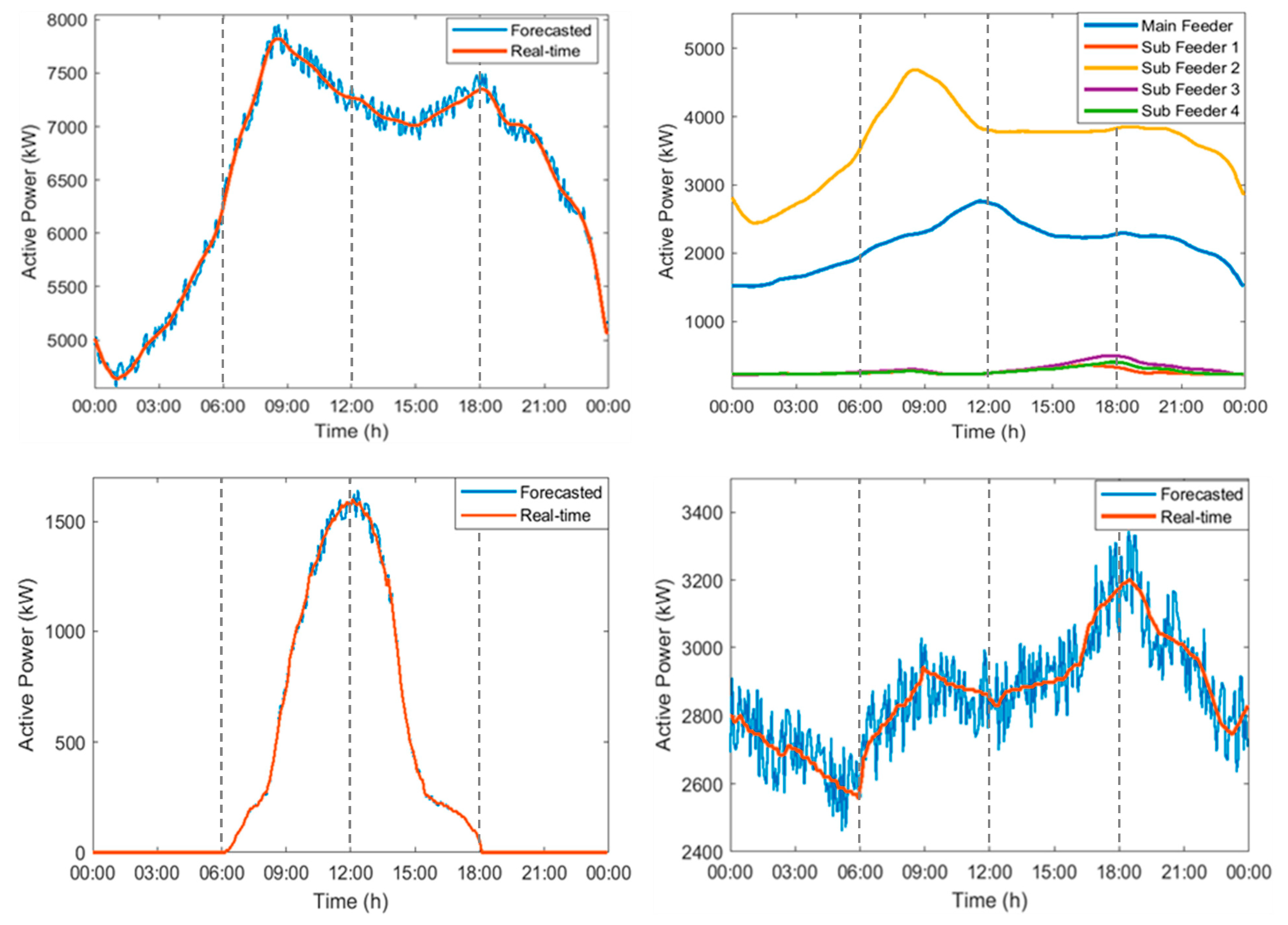
The load profile for the 34-bus system is generated considering a total connected load of approximately10 MVA with a mix of residential and commercial loads, although the different types of loads are not profiled separately. As mentioned in the previous section, the 34-bus network consists of a main feeder along with four laterals, and thus, the load profiles for all the feeders are also presented here. Figure 4 shows the typical day-ahead load profile and the load distribution in the feeders with a 5% expected error in forecasted data compared to the real-time data.
The solar energy profile is modeled considering a location from among the arid tropical regions. A typical profile in such regions shows that the solar energy availability begins near sunrise and ends near sunset with the peak at noon, provided the environmental conditions allow clear sun availability. The forecasted data on the solar energy availability is considered to be within an error range of 5% of the real-time data, and thus, the profile for such a scenario is used and presented in Figure 4. From the plot, it can be observed that the solar energy rises and drops with a pattern spanning 6-h each.
The WT is profiled based on references from the literature [8] considering widely variant and intermittent wind availability. Figure 4 presents the profile for the forecasted WT power with an expected error range of 5% of the real-time WT power. The peak in the profile shown in the figure is presented as close to the best available WT power in the previously considered tropical region with respect to its maximum capacity.

4.2. Operating Parameters of Generating Units

The system models for the dispatchable generating units and their respective operational constraints were discussed in the previous sections. This section provides data on the previously presented generator models along with their operational parameters and cost coefficients. Table 2 presents the operational power limits along with the minimum startup time and shut-down time, the fuel cost coefficients, and the startup costs of all the generating units. It is to be noted that the minimum power for each unit is set based on the minimum loading required to utilize the units at the best of their efficiencies. The cost coefficients related to fuel consumption, the startup cost, and the operation and maintenance costs of the dispatchable units are presented in Table 3.
As previously mentioned, the MT units have a nearly linear fuel consumption curve due to their relatively good part-load efficiencies, and thus, the cost curve characteristics can be linear as shown in Table 3. The SoC limits of the BSS include the maximum and minimum levels set at 100% and 30%, respectively. The cost coefficients, all in AED/kW/h, include the operation and maintenance cost set at 0.005 and the cost of discharging set at 0.8, while the cost of charging is subject to the dispatchable unit that was turnedon the latest, as per Equation (15). An important parameter here is the initial SoC of the BSS, which is set at 72% [42].

4.3. Simulation Outcome Part1: Power Schedule and Dispatch

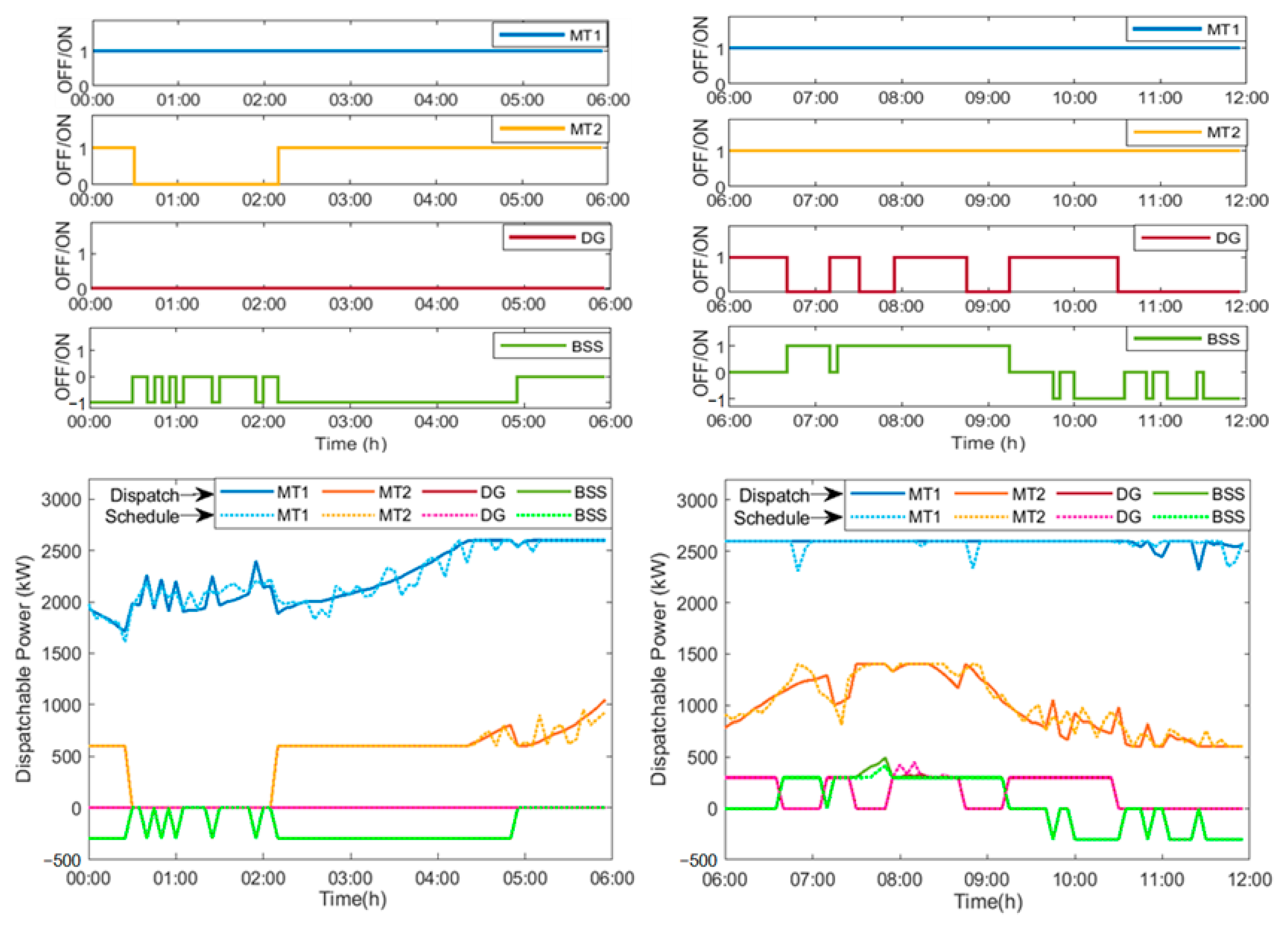
As specified earlier, each of the four quarters in the 24-h horizon consist of both the schedule stage as well as the dispatch stage. The simulation is executed in MATLAB R2020, where the strategy is evaluated from quarter ‘1’ (beginning of the day), ‘Q1’ through each quarter, to the last one (‘Q2’, ‘Q3’, and ‘Q4’). Figure 5 and Figure 6 depict plots from both the stages of power dispatch, where at the top of each figure the control states of the DER units (0 or 1, also −1 in case of BSS) are plotted, while the bottom parts show the power levels during both the stages.
Figure 5 and Figure 6 show the dispatched power curves aligned below the scheduled control state of the units. It is to be noted that the DER units present in the plots are those of the dispatchable units, thus, not including the PV and WT. Among all the plots, as per expectations, MT1 and MT2 seem to be energized for most of the 24-h period owing to their lower cost of operation compared to the DG and BSS. This is also advantageous due to the part-load efficiencies of the MT units. As for the rest, the DG is shown to be energized occasionally following the minimum up and down time constraints, while the BSS is shown to be functioning following the charge/discharge strategy as in [42].
There are some observations that can be made from the previous figures. For instance, at the beginning of Q1, the BSS is charged repeatedly, although intermittently, while remaining idle the rest of the quarter. This can be attributed to the initial SoC of the BSS and the lower load demand during the period, as observed from Figure 4. In the rest of the quarters, however, the BSS is functional in all three modes of operation, especially due to the rise in demand that requires the BSS to supply power, in spite of which the SoC at the end of the horizon is found to be close to the initial SoC (72%). This facilitates better use of the BSS while also increasing its lifetime.
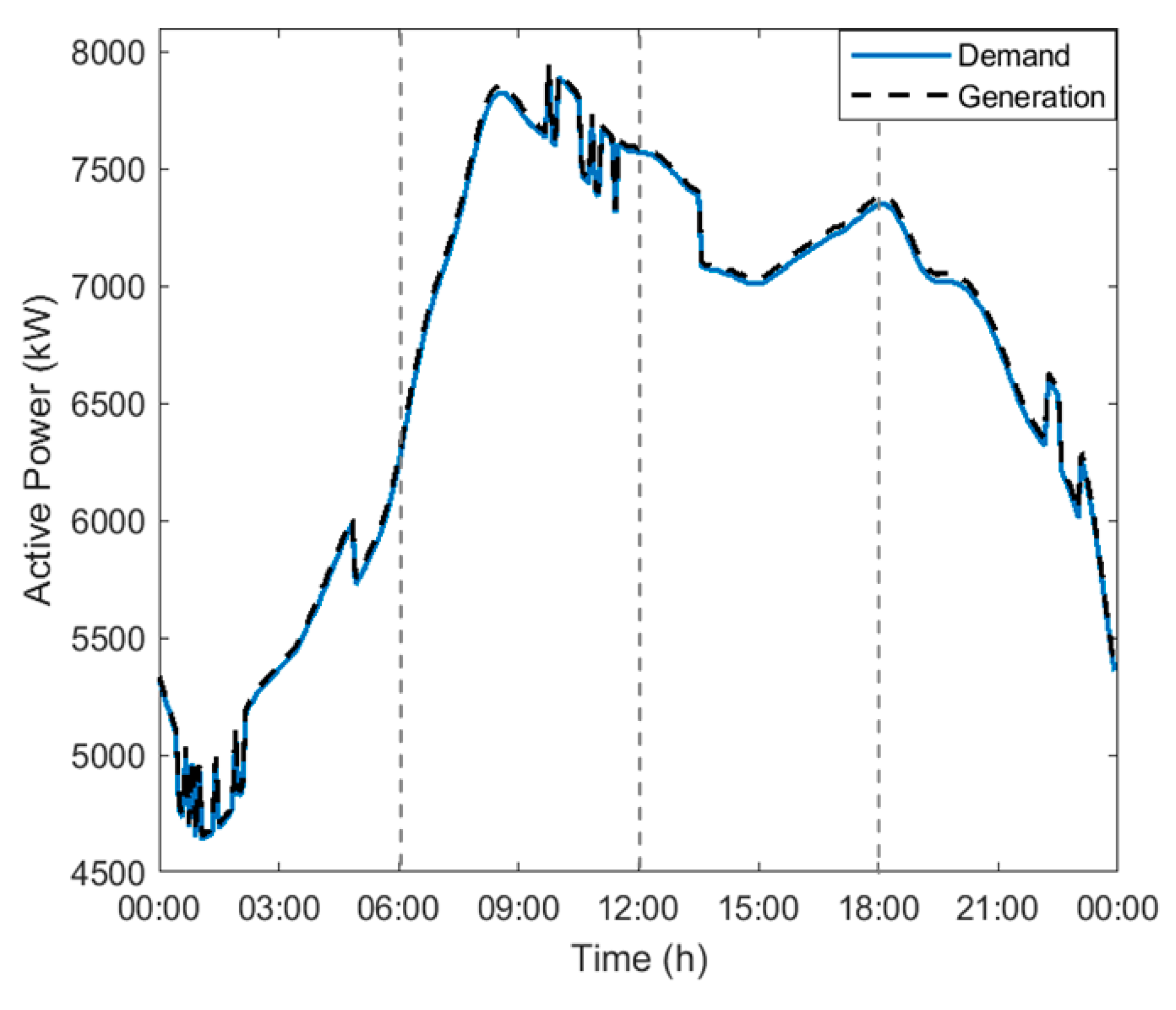
The dispatch figures in all four quarters can be seen with dual plots, one each for the two stages. The dotted plots present the pre-scheduled power levels obtained by solving the objective function in the first stage as a mixed-integer problem, along with the control states of the DER, while the solid plots present the dispatched power levels obtained from the second stage. A clear observation from the plots is the closeness of the output obtained from either stage, except for the regular ups and downs in the dotted plots which is due to the forecast errors duly covered for by the reserved power in the dispatch stage. On the other hand, the plot in Figure 7 shows a whole view of the demand and generation for the 24-h period where a very slight difference can be noted between them due to the network losses incurred. This network loss is calculated by the Backward/Forward Sweep method that is obtained through the power flow analysis, which is mainly performed to obtain data on the bus voltages and the line currents.

4.4. Simulation Outcome Part2: Validating C-PSO

The proposed strategy is executed (with the 34-bus system) using the proposed C-PSO and is also executed using the standard PSO with the same parameters, for validation. In both optimizers, the swarm size was set at 50, the number of decision variables was four including two MTs, the DG and the BSS, and the maximum iteration was set at 500 amounting to a total of 25,000 function evaluations. Apart from the parameters, it is to be noted that both the optimizers solve the mixed-integer type problem in the first stage of the dual-stage dispatch by selectively optimizing the decision variables. This is achieved by iteratively updating each particle position as a product of the calculated position and the control state of the DER units, ‘U’, such that when ‘U’ is zero, the decision variable ends up with a zero value depicting a turned ‘OFF’ DER unit.
Table 4 presents an hourly data on the simulation of the proposed strategy using both the optimizers for the 24-h period. It shows a count of 5-min time-steps of their operation in all the quarters, along with the generation costs during those periods. Thus, the tables show the UC obtained by the optimizers, rather than the scheduled power values due to the large number of time instances (288) considered in the one-day horizon. It is to be noted that each hour consists of 12-time instances, such that a count of 12 would mean the unit is turned ‘ON’ throughout the hour. Additionally, the hourly data on the SoC levels of BSS is also obtained from the dispatch stage, which corresponds to its schedule.
The data on PSO-based schedule from Table 4 shows the operational hours of the units MT1, MT2, DG, and BSS (Discharge/Charge) as 24 h, 20 h and 15 min, 19 h and 15 min, and 7.5 h/6 h and 55 min, respectively. Similarly, the operational hours on C-PSO-based schedule is 24 h, 22 h and 20 min, 8 h and 5 min, and 6 h and 20 min/8 h and 5 min, respectively, for MT1, MT2, DG, and BSS (Discharge/Charge).
The difference between either optimizer is in the number of hours the costlier DG unit and the BSS discharge are scheduled for use. The PSO-based schedule is shown to have scheduled roughly 4 h of additional operation for the DG and approximatelyan hour in excess for the BSS as compared with the C-PSO schedule. This shows the inefficiency of the PSO in scheduling the power levels effectively, which is one among the reasons for the development of C-PSO. This observation indicates that the schedule provided by the C-PSO is optimal with an evident support from the power plots of both the dispatch stages. Additional evidence in difference is obtained from Table 4, where the SoC level as per PSO ends at a very low value of 51.1% as compared to the initial level of approximately70%. This is the opposite in the schedule by C-PSO where the initial level is matched by an ending SoC level of 72.35%. While the charge cycles are similar in both cases, C-PSO provides greater lifetime to the BSS by optimizing the discharge hours and reducing the depth to which it is discharged, providing financial gain with respect to its O&M costs.
The main comparison can be done based on the output of the optimization problem here, which is the total generation cost. The hourly total costs provided in Table 4 are those obtained in the dispatch stage, which show that the average total generation costs per day are AED 16064 and AED 14830, respectively, for the dual-stage dispatch achieved by using PSO and C-PSO, with the latter providing a difference of 7.7%.

4.5. Simulation Outcome Part3: Validating Split-Horizon Dual-Stage Dispatch Strategy

The basis for the proposed split-horizon dual-stage dispatch strategy is the fact that the forecast accuracy of RE availability is higher in shorter forecast periods (6 h here) than the traditional 24-h period for the daily energy dispatch problem. Accordingly, the amount of power to be reserved during scheduling is decided based on the forecast uncertainty. Thus, it is understood that the forecast uncertainty is bound to be lower in the proposed method than in the traditional 24-h forecast horizon. Utilizing similar system characteristics (power profiles) previously presented, the proposed dual-stage dispatch strategy is validated with the 34-bus system in comparison with a traditional 24-h dispatch problem. Table 5 shows a comparative hourly data on the Traditional Dispatch (TD) as well as the Split-Horizon Dispatch (SHD) strategy.
The major difference in the strategies is in the percentage forecast error of the RE units, which is 5% in the proposed strategy, while it is considered to be 10% for the traditional one owing to the larger forecast horizon and subsequent lead-time. The difference in the uncertainty is considered with the assumption that the forecasting techniques used for the RE are the same in either case, respectively. The proposed C-PSO optimizer is utilized for the comparative analysis since it was already validated in the previous section.
The TD strategy is simulated separately with an initial SoC level equivalent to the SHD simulation data. From Table 5, it is clearly observable that the total number of operational hours of each DER in TD strategy is higher than in the case of the SHD strategy. This is justified with the amount of hourly reserve required to cover up for the RE forecast uncertainty in either strategy, as shown in the table. Firstly, the units MT2 and DG run approximately1 h 15 min each more in the TD strategy in comparison to in the SHD; secondly, the BSS discharges approximately one and a half hours more in the former than in the latter, which causes a lower SoC level (50%) at the end of the TD time horizon. The second observation shows the proposed method to be facilitating better optimization of the BSS power, as observed in the previous two sub sections, providing greater lifetime to the BSS while also allowing lower O&M requirement and subsequent costs. The average power reserve required in each of the strategies per quarter is presented in Figure 8, which averages at an hourly reserve per day of 651.56 kW for the TD strategy, while it is observed to be 358.64 kW for the SHD strategy, amounting to a 45% difference in the reserve requirement.
The observed differences in either strategy provide ample justification to have a reduced forecast uncertainty, which is also supported by the difference between their costs: AED 15410 and AED 14830, respectively, for TD and SHD. The 3.7% difference excludes penalties for the reserve constraint violation in the TD strategy since it is specific to system design, including DER operational limits.

4.6. Scalability Verification: 69-Bus System

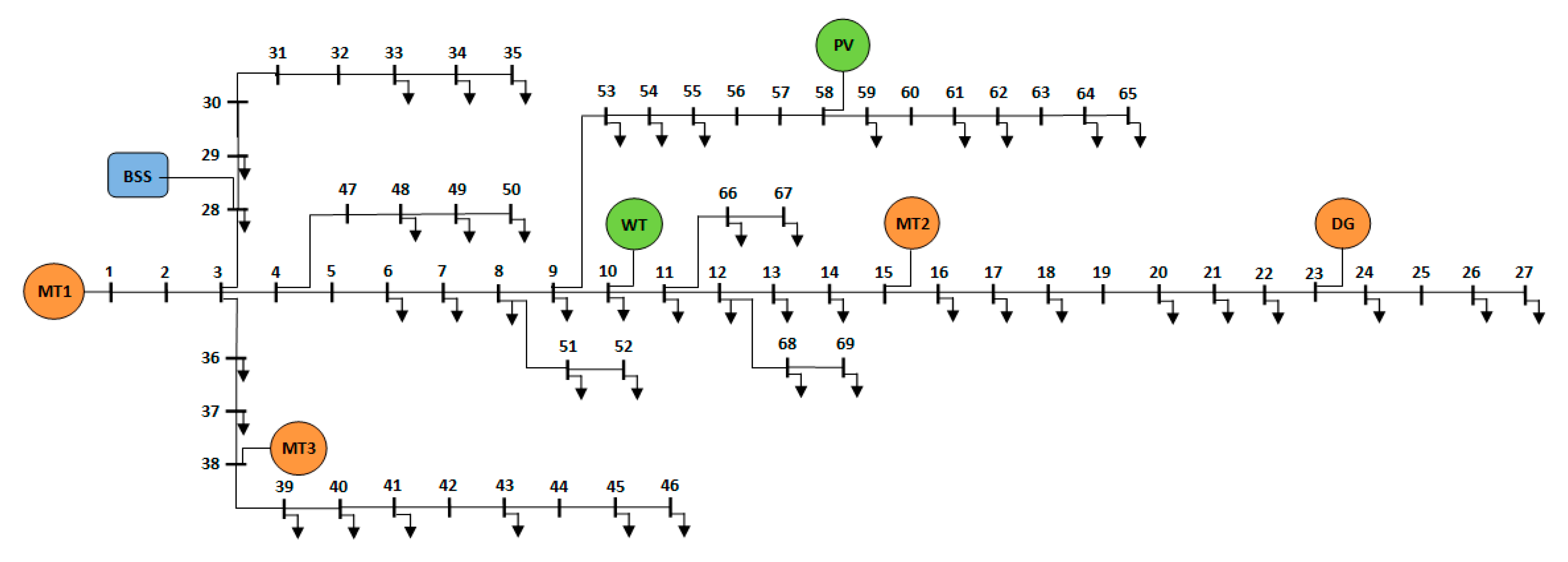
The network in Figure 9 depicts a modified IEEE 69-node test feeder [43] that has three MT units, 1 DG unit, 1 BSS unit, a PV, and a WT unit as part of the modification to transform the network into an MG, where MT1 serves as the slack generator. In comparison with the 34-bus system, this network has 15 additional PQ buses with higher PV (2.5 MW) and WT (4 MW) capacities and an additional MT unit MT3 (800 kW) owing to higher base (approximately6 MW) and peak power (approximately8.5 MW). This has increased the base power of the system to 17 MVA at 11 kV system voltage.
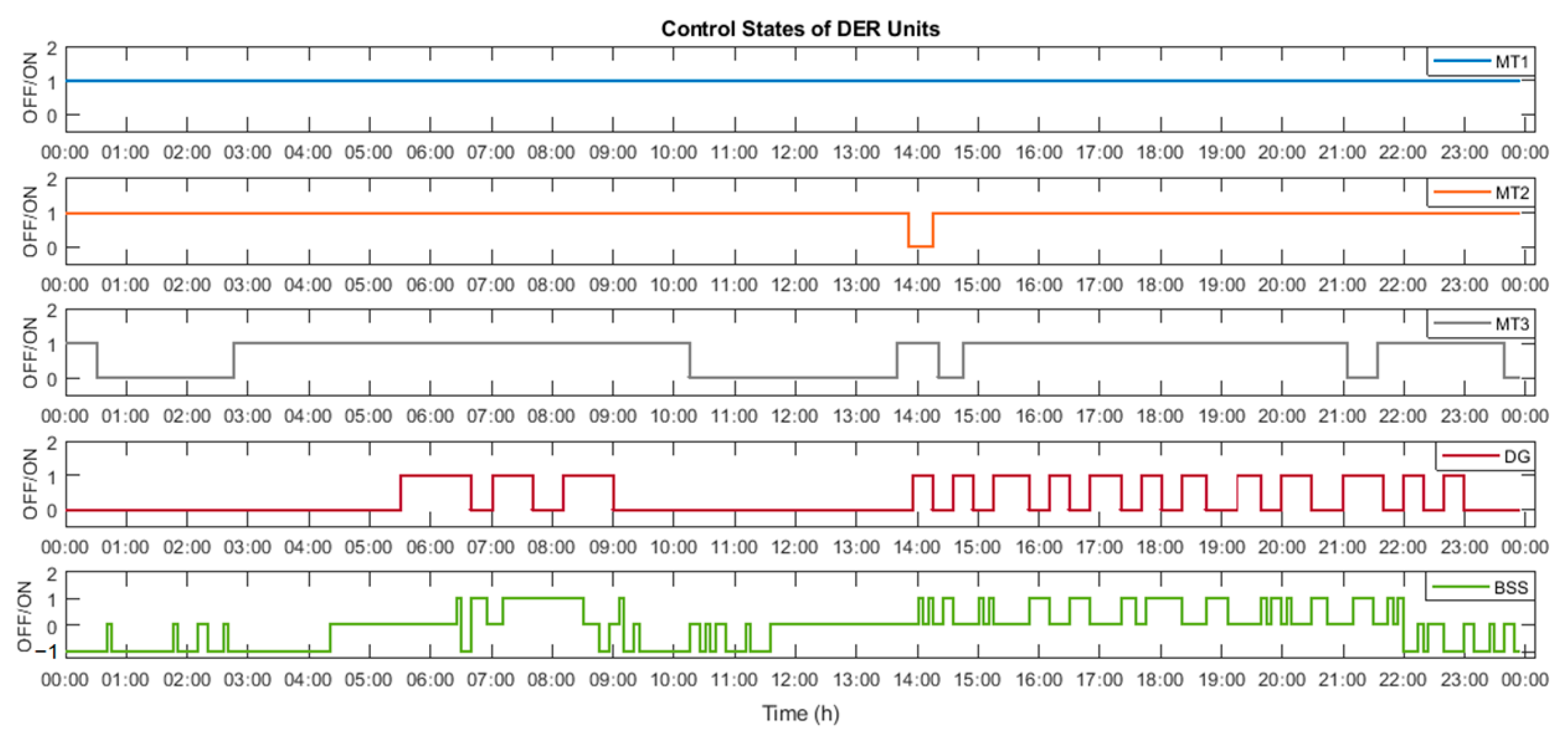
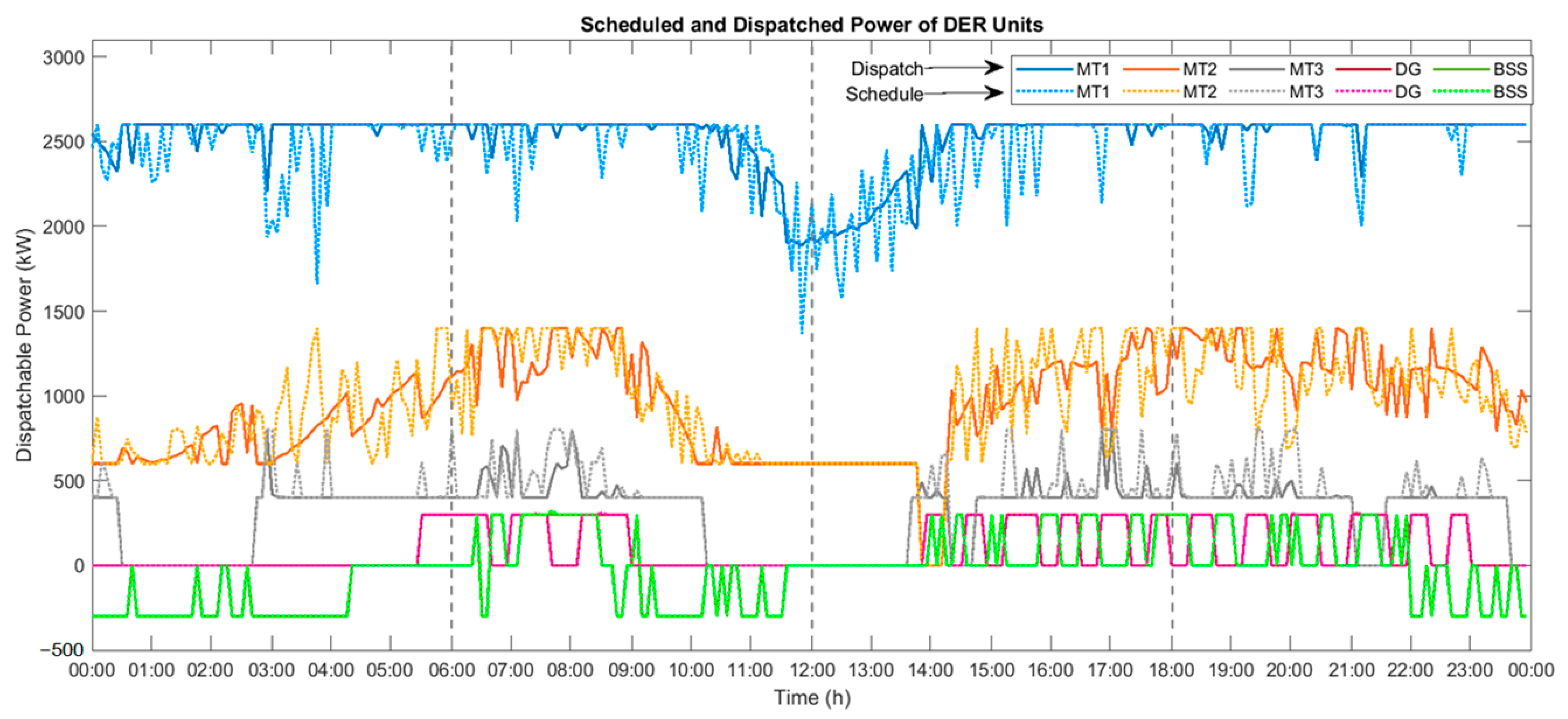
Figure 10 and Figure 11 present the outcomes from the unit commitment and economic dispatch, respectively, performed using the proposed split-horizon dual-stage dispatch strategy. It can be noted that the scheduled power, as per the commitment attained during the first stage of dual-stage dispatch, is utilized very well as a reference to obtain the power curves for the dispatchable generator units in the second stage of the dispatch problem. In comparison with previously analyzed simulations, it is understood that the DERs are very aptly utilized for power scheduling and dispatching alike, proving the scalability of the proposed strategy, as well as the usability of the optimizer for larger and complex systems and problems.
The key results from the simulations presented in this section are highlighted in Table 6.

5. Conclusions

This paper aims to provide a solution to the daily dispatch problem for a standalone MG, and as such, a split-horizon dual-stage dispatch strategy was proposed with the method of “splitting” the dispatch horizon of 24-h into four quarters to utilize the accuracies of existing forecast methods efficiently. Additionally, a novel variant of the inertia-weight-based PSO was proposed as Customized-PSO, which tackled the complexity of the mixed-integer problem in the first stage of the dispatch strategy, subsequently providing optimal solutions to the dual-stage dispatch problem.
The proposed strategy was implemented via MATLAB simulations on a modified IEEE 34-node test feeder. The outcomes of the simulations were used to validate the proposed optimizer C-PSO and the split-horizon strategy. The proposed C-PSO proved much more efficient than the standard PSO in executing the proposed strategy, providing a 7.7% improvement in total generating costs. This enabled the validation of the strategy itself, in comparison with the traditional 24-h dispatch strategy, where a 3.7% improvement in total generating costs was observed. These provide ample justification to claim that the proposed methodology and optimizer contribute towards effective resource management since the dispatch problem was optimized considering the DER operational constraints, as well as the networks’ constraints, albeit under specific network designs.
The proposed work, however, considers a few assumptions, such as having a fixed range for the forecast errors, in order to present certain case scenarios to remain within the scope of work presented. Nonetheless, this can be changed by considering a few exact scenarios, especially with respect to forecasting methodologies. The following few directions can be considered as scope for future work:
  • Using a commercial or a research-based forecasting technique for RE availability check considering forecasting periods of 24 h and a lower period of 6 h to practically verify the forecast uncertainty and its effect on the proposed dispatch scheme.
  • Including responsive loads in the network to improve the demand profile further by allowing a limited shifting of load throughout the horizon.
Author Contributions

Conceptualization, A.A. and H.S.; methodology, A.A.; software, A.A.; validation, A.A.; formal analysis, A.A. and H.S.; investigation, A.A. and H.S.; resources, H.S. and F.A.; data curation, A.A.; writing—original draft preparation, A.A.; writing—review and editing, A.A. and H.S.; visualization, A.A. and H.S.; supervision, H.S. and F.A.; funding acquisition, F.A. All authors have read and agreed to the published version of the manuscript.

Funding

This research was funded by ICT Fund UAE, grant number 21N206 and Asian Universities Alliance (AUA)–United Arab Emirates University (UAEU) Joint Research Program under grant G00004215.

Data Availability Statement

The data presented in this study are available on request from the corresponding author.

Acknowledgments

The authors would like to express their gratitude to the UAE University for providing support in the form of infrastructure, funds and tools for this research work.

Conflicts of Interest

The authors declare no conflict of interest.

Appendix A

The information on the used benchmark functions for the validation of C-PSO are presented here with test parameters and mathematical functions. It is to be noted that the functions F1 through to F5 are ‘unimodal’ functions, while F6 to F10 represent multimodal functions.
Table A1. Details on benchmark functions.
Function No.Function NameDimensionSearch SpaceOptimum Value
F1Schwefel 2.2160[−100,100]0
F2Booth2[−10,10]0
F3Schwefel 2.2240[−10,10]0
F4Schwefel 1.250[−100,100]0
F5Easom2[−100,100]−1
F6Rastrigin20[−5.12,5.12]0
F7Branin2[−5,15]0.397887
F8Griewank30[−600,600]0
F9Goldstein–Price2[−2,2]3
F10Levi2[−100,100]0
Table A2. Mathematical functions of benchmark functions.
Function No.Function
F1 m a x x i , 1 i n
F2 x 1 + 2 x 2 7 2 + 2 x 1 + x 2 5 2
F3 i = 1 n x i + i = 1 n x i
F4 i = 1 n j = 1 i x j 2
F5 cos x 1 cos x 2 e x 1 π 2 x 1 π 2
F6 i = 1 n x i 2 10 cos 2 π x i + 10
F7 x 2 5.1 4 π 2 x 1 2 + 5 π x 1 6 2 + 10 1 + 1 8 π cos x 1 + 10
F8 1 4000 i = 1 n x i 2 i = 1 n cos x i i + 1
F9 1 + x 1 + x 2 + 1 2 19 14 x 1 + 3 x 1 2 14 x 2 + 6 x 1 x 2 + 3 x 2 2 30 + 2 x 1 3 x 2 2 18 32 x 1 + 12 x 1 2 + 48 x 2 36 x 1 x 2 + 27 x 2 2
F10 sin 2 3 π x 1 + x 1 1 2 1 + sin 2 3 π x 2 + x 2 1 2 1 + sin 2 2 π x 2

References

  1. Lasseter, R.; Akhil, A.; Marnay, C.; Stephens, J.; Dagle, J.; Guttromsom, R.; Meliopoulous, A.S.; Yinger, R.; Eto, J. Integration of Distributed Energy Resources: The CERTS Microgrid Concept; Report No.: LBNL-50829; Lawrence Berkeley National Laboratory: Berkeley, CA, USA, 2002.
  2. Meng, L.; Sanseverino, E.R.; Luna, A.; Dragicevic, T.; Vasquez, J.C.; Guerrero, J.M. Microgrid supervisory controllers and energy management systems: A literature review. Renew. Sustain. Energy Rev. 2016, 60, 1263–1273. [Google Scholar] [CrossRef]
  3. Zia, M.F.; Elbouchikhi, E.; Benbouzid, M. Microgrids energy management systems: A critical review on methods, solutions, and prospects. Appl. Energy 2018, 222, 1033–1055. [Google Scholar] [CrossRef]
  4. Roslan, M.F.; Hannan, M.A.; Ker, P.J.; Uddin, M.N. Microgrid control methods toward achieving sustainable energy management. Appl. Energy 2019, 240, 583–607. [Google Scholar] [CrossRef]
  5. Eseye, A.T.; Zhang, J.; Zheng, D.; Wei, D. Optimal energy management strategy for an isolated industrial microgrid using a modified particle swarm optimization. In Proceedings of the 2016 IEEE International Conference on Power and Renewable Energy (ICPRE), Shanghai, China, 21–23 October 2016; pp. 494–498. [Google Scholar]
  6. Minchala-Avila, L.I.; Garza-Castanon, L.; Zhang, Y.; Ferrer, H.J.A. Optimal Energy Management for Stable Operation of an Islanded Microgrid. IEEE Trans. Ind. Inform. 2016, 12, 1361–1370. [Google Scholar] [CrossRef] [Green Version]
  7. Zhu, D.; Yang, R.; Hug-glanzmann, G. Managing microgrids with intermittent resources: A two-layer multi-step optimal control approach. In Proceedings of the 2010 North American Power Symposium, Arlington, TX, USA, 26–28 September 2010. [Google Scholar]
  8. Jiang, Q.; Xue, M.; Geng, G. Energy management of microgrid in grid-connected and stand-alone modes. IEEE Trans. Power Syst. 2013, 28, 3380–3389. [Google Scholar] [CrossRef]
  9. Sachs, J.; Sawodny, O. A Two-Stage Model Predictive Control Strategy for Economic Diesel-PV-Battery Island Microgrid Operation in Rural Areas. IEEE Trans. Sustain. Energy 2016, 7, 903–913. [Google Scholar] [CrossRef]
  10. Taha, M.S.; Abdeltawab, H.H.; Mohamed, Y.A.R.I. An online energy management system for a grid-connected hybrid energy source. IEEE J. Emerg. Sel. Top. Power Electron. 2018, 6, 2015–2030. [Google Scholar] [CrossRef]
  11. Moretti, L.; Polimeni, S.; Meraldi, L.; Raboni, P.; Leva, S.; Manzolini, G. Assessing the impact of a two-layer predictive dispatch algorithm on design and operation of off-grid hybrid microgrids. Renew. Energy 2019, 143, 1439–1453. [Google Scholar] [CrossRef]
  12. Solanki, B.V.; Canizares, C.A.; Bhattacharya, K. Practical Energy Management Systems for Isolated Microgrids. IEEE Trans. Smart Grid 2018, 10, 4762–4775. [Google Scholar] [CrossRef]
  13. Almada, J.B.; Leão, R.P.S.; Sampaio, R.F.; Barroso, G.C. A centralized and heuristic approach for energy management of an AC microgrid. Renew. Sustain. Energy Rev. 2016, 60, 1396–1404. [Google Scholar] [CrossRef]
  14. Belila, A.; Benbouzid, M.; Berkouk, E.M.; Amirat, Y. On energy management control of a PV-diesel-ESS based microgrid in a stand-alone context. Energies 2018, 11, 2164. [Google Scholar] [CrossRef] [Green Version]
  15. Chalise, S.; Sternhagen, J.; Hansen, T.M.; Tonkoski, R. Energy management of remote microgrids considering battery lifetime. Electr. J. 2016, 29, 1–10. [Google Scholar] [CrossRef]
  16. Gao, H.C.; Choi, J.H.; Yun, S.Y.; Lee, H.J.; Ahn, S.J. Optimal scheduling and real-time control schemes of battery energy storage system for microgrids considering contract demand and forecast uncertainty. Energies 2018, 11, 1371. [Google Scholar] [CrossRef] [Green Version]
  17. Sukumar, S.; Mokhlis, H.; Mekhilef, S.; Naidu, K.; Karimi, M. Mix-mode energy management strategy and battery sizing for economic operation of grid-tied microgrid. Energy 2017, 118, 1322–1333. [Google Scholar] [CrossRef] [Green Version]
  18. Moradi, H.; Esfahanian, M.; Abtahi, A.; Zilouchian, A. Optimization and energy management of a standalone hybrid microgrid in the presence of battery storage system. Energy 2018, 147, 226–238. [Google Scholar] [CrossRef]
  19. Geramifar, H.; Shahabi, M.; Barforoshi, T. Coordination of energy storage systems and DR resources for optimal scheduling of microgrids under uncertainties. IET Renew. Power Gener. 2017, 11, 378–388. [Google Scholar] [CrossRef]
  20. Helal, A.; Najee, R.J.; Hanna, M.O.; Shaaban, M.F.; Osman, A.H.; Hassan, M.S. An energy management system for hybrid microgrids in remote communities. In Proceedings of the 2017 IEEE 30th Canadian Conference on Electrical and Computer Engineering, Windsor, ON, Canada, 30 April–3 May 2017; pp. 1–4. [Google Scholar]
  21. Adefarati, T.; Bansal, R.C.; Bettayeb, M.; Naidoo, R. Optimal energy management of a PV-WTG-BSS-DG microgrid system. Energy 2021, 217, 119358. [Google Scholar] [CrossRef]
  22. Ahmad Khan, A.; Naeem, M.; Iqbal, M.; Qaisar, S.; Anpalagan, A. A compendium of optimization objectives, constraints, tools and algorithms for energy management in microgrids. Renew. Sustain. Energy Rev. 2016, 58, 1664–1683. [Google Scholar] [CrossRef]
  23. Leonori, S.; Martino, A.; FrattaleMascioli, F.M.; Rizzi, A. Microgrid Energy Management Systems Design by Computational Intelligence Techniques. Appl. Energy 2020, 277, 115524. [Google Scholar] [CrossRef]
  24. Wolpert, D.H.; Macready, W.G. No free lunch theorems for optimization. IEEE Trans. Evol. Comput. 1997, 1, 67–82. [Google Scholar] [CrossRef] [Green Version]
  25. U.S. Agency for International Development. Grid Integration Series: Variable Renewable Energy Forecasting. 2020. Available online: https://www.usaid.gov/sites/default/files/documents/1865/USAID_SURE_Variable-Renewable-Energy-Forecasting.pdf (accessed on 22 March 2023).
  26. Orwig, K.; Hodge, B.M.; Brinkman, G.; Ela, E.; Milligan, M.; Banunarayanan, V.; Nasir, S.; Freedman, J. Economic Evaluation of Short-Term Wind Power Forecasts in ERCOT: Preliminary Results; Report No.: NREL/CP-5500-56257; Nat. Renewable Energy Lab.: Golden, CO, USA, 2012. Available online: https://www.nrel.gov/docs/fy12osti/56257.pdf (accessed on 22 March 2023).
  27. Zhang, J.; Hodge, B.M.; Florita, A.; Lu, S.; Hamann, H.F.; Banunarayanan, V. Metrics for Evaluating the Accuracy of Solar Power Forecasting; Nat. Renewable Energy Lab.: Golden, CO, USA, 2013; Report No.: NREL/CP-5000-60142. Available online: https://www.nrel.gov/docs/fy14osti/60142.pdf (accessed on 22 March 2023).
  28. International Renewable Energy Agency. Innovation Landscape Brief: Advanced Forecasting of Variable Renewable Power Generation. 2020. Available online: https://www.irena.org/-/media/Files/IRENA/Agency/Publication/2020/Jul/IRENA_Advanced_weather_forecasting_2020.pdf%20?%20%20la=en&hash=8384431B56569C0D8786C9A4FDD56864443D10AF (accessed on 22 March 2023).
  29. Akhter, M.N.; Mekhilef, S.; Mokhlis, H.; Shah, N.M. Review on forecasting of photovoltaic power generation based on machine learning and metaheuristic techniques. IET Renew. Power Gener. 2019, 13, 1009–1023. [Google Scholar] [CrossRef] [Green Version]
  30. Salama, M.M.A.; Chikhani, A.Y. A simplified network approach to the var control problem for radial distribution systems. IEEE Trans. Power Deliv. 1993, 8, 1529–1535. [Google Scholar] [CrossRef]
  31. Diaf, S.; Diaf, D.; Belhamel, M.; Haddadi, M.; Louche, A. A methodology for optimal sizing of autonomous hybrid PV/wind system. Energy Policy 2007, 35, 5708–5718. [Google Scholar] [CrossRef] [Green Version]
  32. Hetzer, J.; Yu, D.C.; Bhattarai, K. An Economic Dispatch Model Incorporating Wind Power. IEEE Trans. Energy Convers. 2008, 23, 603–611. [Google Scholar] [CrossRef]
  33. Capstone C1000 Series Microturbine Systems Technical Reference; Report No. 410072 Rev B; Capstone Turbine Corporation: Chatsworth, CA, USA, 2011; Available online: https://globalmicroturbine.com/search/c1000/capstone-c1000-series-microturbine-systems-technical-referen-001.html (accessed on 22 March 2023).
  34. Ericson, S.J.; Olis, D.R. A Comparison of Fuel Choice for Backup Generators; Report No.: NREL/TP-6A50-72509; Nat. Renewable Energy Lab.: Golden, CO, USA, March 2019. Available online: https://www.nrel.gov/docs/fy19osti/72509.pdf (accessed on 22 March 2023).
  35. Wood, A.J.; Wollenberg, B.F.; Shelbe, G.B. Transmission System Effects. In Power Generation, Operation, and Control, 3rd ed.; John Wiley & Sons, Inc.: Hoboken, NJ, USA, 2014; pp. 253–277. [Google Scholar]
  36. Jabari, F.; Sohrabi, F.; Pourghasem, P.; Mohammadi-Ivatloo, B. Backward-Forward Sweep Based Power Flow Algorithm in Distribution Systems. In Optimization of Power System Problems; Springer: Cham, Switzerland, 2020; pp. 365–382. [Google Scholar]
  37. Kennedy, J.; Eberhart, R.C. Particle Swarm Optimization. In Proceedings ofthe ICNN’95–International Conference on Neural Networks, Perth, WA, Australia, 27 November–1 December 1995; pp. 1942–1948. [Google Scholar]
  38. Shi, Y.; Eberhart, R. A modified particle swarm optimizer. IEEE International Conference on Evolutionary Computation Proceedings. In Proceedings of the IEEE World Congress on Computational Intelligence (Cat. No.98TH8360), Anchorage, AK, USA, 4–9 May 1998; pp. 69–73. [Google Scholar]
  39. Trelea, I.C. The particle swarm optimization algorithm: Convergence analysis and parameter selection. Inf. Process. Lett. 2003, 85, 317–325. [Google Scholar] [CrossRef]
  40. Prasanthi, A.; Shareef, H.; Errouissi, R.; Asna, M.; Wahyudie, A. Quantum Chaotic Butterfly Optimization Algorithm with Ranking Strategy for Constrained Optimization Problems. IEEE Access 2021, 9, 114587–114608. [Google Scholar] [CrossRef]
  41. Naruei, I.; Keynia, F. A new optimization method based on coot bird natural life model. Expert Syst. Appl. 2021, 183, 115352. [Google Scholar] [CrossRef]
  42. Amir, A.; Shareef, H.; Awwad, F. Load Factor Improvement in a Standalone Microgrid using Battery Energy Storage System. In Proceedings of the 2022 3rd International Conference on Smart Grid and Renewable Energy (SGRE), Doha, Qatar, 20–22 March 2022; pp. 1–5. [Google Scholar] [CrossRef]
  43. Kadir, A.F.A.; Mohamed, A.; Shareef, H.; Wanik, M.Z.C. Optimal placement and sizing of distributed generations in distribution systems for minimizing losses THDv using evolutionary programming. Turk. J. Electr. Eng. Comput. Sci. 2013, 21, 2269–2282. [Google Scholar] [CrossRef]
Figure 1. Modified IEEE 34-node test feeder modeled as a Microgrid Network.
Energies 16 03400 g001
Figure 2. Pseudo code of proposed C-PSO.
Energies 16 03400 g002
Figure 3. Flowchart depicting the split-horizon dual-stage dispatch strategy.
Energies 16 03400 g003
Figure 4. Forecasted and real-time data for 34-bus system: (top) total load profile and load profile by feeder; (bottom) PV and WT power profiles.
Energies 16 03400 g004
Figure 5. Simulation outcome for 34-bus system from Quarters ‘1’ (Q1, left) and ‘2’ (Q2, right): (top) control states of DER units; (bottom) dispatched power of DER units.
Energies 16 03400 g005
Figure 6. Simulation outcome for 34-bus system from Quarters ‘3’ (Q3, left) and ‘4’ (Q4, right): (top) control states of DER units; (bottom) dispatched power of DER units.
Energies 16 03400 g006
Figure 7. Demand vs. generation for 34-bus system.
Energies 16 03400 g007
Figure 8. Average power reserve in each quarter.
Energies 16 03400 g008
Figure 9. Larger microgrid network: modified IEEE 69-node test feeder.
Energies 16 03400 g009
Figure 10. Simulation outcome for 69-bus system: control states for DER units.
Energies 16 03400 g010
Figure 11. Simulation outcome for 69-bus system: scheduled and dispatched power of DER units.
Energies 16 03400 g011
Table 1. Comparative results of executed benchmark functions.
Function No.ParametersC-PSOBOACOOTPSO
F1RMSE1.32 × 10−303.68 × 10−171.63 × 10−102.61 × 101
Best7.38 × 10−352.54 × 10−182.33 × 10−271.95 × 101
Worst8.10 × 10−301.34 × 10−161.03 × 10−93.48 × 101
SD1.27 × 10−302.76 × 10−171.61 × 10−103.89 × 100
F2RMSE09.28 × 10−12.35 × 10−60
Best06.90 × 10−51.98 × 10−90
Worst04.42 × 10−19.55 × 10−60
SD07.59 × 10−21.95 × 10−60
F3RMSE1.09 × 10−305.01 × 10171.24 × 10−81.59 × 101
Best2.85 × 10−361.04 × 10−173.29 × 10−289.41 × 100
Worst7.49 × 10−302.28 × 10188.80 × 10−82.46 × 101
SD1.08 × 10−304.73 × 10171.24 × 10−84.13 × 100
F4RMSE1.49 × 10−579.09 × 10−198.82 × 10−261.12 × 10⁴
Best1.26 × 10−694.41 × 10−215.99 × 10−604.44 × 10³
Worst1.02 × 10−563.94 × 10−186.23 × 10−252.38 × 10⁴
SD1.48 × 10−578.31 × 10−198.81 × 10−264.71 × 10³
F5RMSE09.99 × 10−17.12 × 10−60
Best−1.00−1.77 × 10⁻³−1.00−1.00
Worst−1.00−2.18 × 10−87−1.00−1.00
SD04.94 × 10−26.78 × 10−60
F6RMSE001.52 × 10−72.81 × 101
Best0001.54 × 101
Worst001.07 × 10−65.30 × 101
SD001.52 × 10−78.54 × 100
F7RMSE3.58 × 10−76.97 × 10−28.62 × 10−53.58 × 10⁻⁷
Best3.98 × 10−13.98 × 10−13.98 × 10−13.98 × 10⁻¹
Worst3.98 × 10−16.55 × 10−13.98 × 10−13.98 × 10⁻¹
SD3.36 × 10−165.56 × 10−27.98 × 10−53.36 × 10⁻¹⁶
F8RMSE005.85 × 10−161.66 × 100
Best0001.19 × 100
Worst004.11 × 10−152.80 × 100
SD005.82 × 10−163.3 × 10⁻¹
F9RMSE7.75 × 10−142.14 × 1007.62 × 10−67.75 × 10⁻¹⁴
Best3.00 × 1003.00 × 1003.00 × 10003.00 × 100
Worst3.00 × 1009.33 × 1003.00 × 10003.00 × 100
SD1.14 × 10−151.68 × 1006.66 × 10−61.23 × 10⁻¹⁵
F10RMSE1.349 × 10−312.12 × 10−12.46 × 10−61.349 × 10⁻³¹
Best1.349 × 10−311.05 × 10−46.50 × 10−111.349 × 10⁻³¹
Worst1.349 × 10−317.65 × 10−19.71 × 10−61.349 × 10⁻³¹
SD2.212 × 10−461.68 × 10−12.19 × 10−61.769 × 10−46
Table 2. Operational power limits of all generating units.
Generator UnitsMaximum Power (kW)Minimum Power (kW)Minimum Startup Time (min)Minimum Shutdown Time (min)
MT1260012002525
MT214006002525
DG5003002020
BSS100030055
Table 3. Cost coefficients of dispatchable units.
Generator UnitsFuel Cost CoefficientsStartup Cost (AED)Operational and Maintenance Cost (AED/kW/h)
a (AED/kW2 h)b (AED/kWh)c (AED/h)
MT100.12480610100.025
MT200.12870610100.025
DG0.00020980.350150.66150.020
Table 4. Comparative dual-stage dispatch data using PSO and C-PSO on an hourly basis.
Time (h)MT1 (NoI *)MT2 (NoI)DG (NoI)BSS (Discharge/Charge) (NoI)SoC (%)Total Cost (AED)
PSOC-PSOPSOC-PSOPSOC-PSOPSOC-PSOPSOC-PSOPSOC-PSO
Q11121256800/80/874.2476.91322.40315.31
2121200300/30/375.9678.63306.86304.47
3121210101200/100/1081.7184.38394.36352.13
412129121200/90/1286.8991.28433.40392.35
5121212121200/120/1193.7997.61488.44454.87
61212712805/30/090.4897.61729.27529.76
Q27121212121283/04/088.3594.77795.83767.33
8121212128511/011/080.5485.78956.80934.62
91212121212912/012/072.0277.251028.60995.18
10121212121293/13/170.4675.70766.08732.35
1112126121266/60/869.3680.30705.19515.59
1212121212600/70/1073.3886.05461.20452.38
Q31312127121005/60/1273.2892.95570.92440.87
1412127121005/50/772.6096.97604.36454.03
1512121212870/00/072.6096.97629.98618.57
16121212121283/04/070.4794.13788.00758.82
17121212121259/010/064.0887.03906.63839.29
181212121212410/011/056.9879.21928.50855.25
Q419121212121259/010/050.5972.11923.54861.48
20121212121256/08/046.3366.43852.75806.82
211212121212113/03/044.1964.30796.80785.61
221212121212110/00/044.1964.30698.93687.65
2312121212240/20/445.3466.60538.09538.13
2412121212000/110/1151.1072.35437.20437.20
Total2882882432682319790/9676/97 16,064.0014,830.00
* NoI—Number of 5-min time instances for which a DER unit is operational.
Table 5. Comparative data on traditional dispatch and proposed dispatch strategies on an hourly basis.
Time (h)MT1 (NoI*)MT2 (NoI)DG (NoI)BSS (Discharge/Charge) (NoI)Average Power Reserve (kW)Total Cost (AED)
TDSHDTDSHDTDSHDTDSHDTDSHDTDSHD
11212126000/120/8518.55283.30317.91315.31
21212120000/120/3508.27277.62309.06304.47
31212710600/100/10517.36283.43375.22352.13
412121212000/120/12526.69289.22389.56392.35
512121212000/50/11539.19297.29460.31454.87
6121212121000/00/0554.34306.83641.93529.76
712121212786/04/0606.47336.42788.70767.33
8121212128510/011/0663.60368.18925.16934.62
91212121212912/012/0722.37400.051028.60995.18
1012121212798/23/1772.89424.79780.35732.35
1112121212464/30/8797.49436.24614.08515.59
1212121212400/90/10806.64439.90467.82452.38
1312121212000/80/12802.63437.49443.45440.87
1412121212000/80/7774.64422.81453.26454.03
1512121212774/00/0712.31391.32683.89618.57
1612121212687/04/0674.24372.39785.28758.82
1712121212758/010/0681.41376.56829.11839.29
1812121212749/011/0690.84381.83856.26855.25
19121212123511/010/0682.80377.77855.38861.48
20121212121511/08/0661.19365.77810.90806.82
211212121241111/03/0648.26358.72837.52785.61
22121212129114/00/0624.27344.87730.44687.65
2312121212641/50/4594.21328.26577.38538.13
2412121212400/110/11556.72306.25448.70437.20
Total28828828326811297106/9676/97651.56358.6415,410.0014,830.00
* NoI—Number of 5-min time instances for which a DER unit is operational.
Table 6. Key observations from the presented simulations.
Simulation OutcomesObjectivesKey Results
Part 1Schedule and Dispatch using SHD (34-bus system)
  • Negligible errors between the dual stages in dispatch
  • SoC of BSS at end of 24-h horizon maintained at a similar value to initial level (~72%) enhancing BSS lifetime and power flexibility in MG system
Part 2Validating C-PSO
  • SoC of BSS at end of 24-h horizon as per PSO (51.1%) is approximately20% less than that of C-PSO (72.35%)
  • C-PSO-based solution provides a 7.7% decrease in total generation costs than that of PSO
Part 3Validating SHD
  • SHD provides a 45% reduction in power reserves than TD due to lower forecast errors
  • SHD provides a 3.7% reduction purely in cost of generation
Part 4Verifying scalability of proposed methods
  • Negligible errors in the dual-stage dispatch problem of the 69-bus system, with no power curtailment or load shedding
Disclaimer/Publisher’s Note: The statements, opinions and data contained in all publications are solely those of the individual author(s) and contributor(s) and not of MDPI and/or the editor(s). MDPI and/or the editor(s) disclaim responsibility for any injury to people or property resulting from any ideas, methods, instructions or products referred to in the content.