Article

Emergency Dispatch Approach for Power Systems with Hybrid Energy Considering Thermal Power Unit Ramping

1
College of Electrical Engineering, Sichuan University, Chengdu 610065, China
2
Intelligent Electric Power Grid Key Laboratory of Sichuan Province, Sichuan University, Chengdu 610065, China
*
Author to whom correspondence should be addressed.
Energies 2023, 16(10), 4213; https://doi.org/10.3390/en16104213
Submission received: 14 April 2023 / Revised: 16 May 2023 / Accepted: 18 May 2023 / Published: 19 May 2023
(This article belongs to the Special Issue Energy Management of Smart Grids with Renewable Energy Resource)

Abstract

:
Future power systems will face more extreme operating condition scenarios, and system emergency dispatch will face more severe challenges. The use of distributed control is a well-designed way to handle this. It enables multi-energy complementation by means of autonomous communication, which greatly improves the flexibility of the grid. First, in the context of global energy conservation and emission reduction, this paper adopts the energy usage method of “renewable energy is the main source of energy, supplemented by thermal power and energy storage” to reduce the system abandoned wind (light) rate while supplementing the energy storage capacity. Second, a consensus algorithm is added to the system while considering the coordination between thermal units and energy storage. An “interface” for autonomous communication between thermal units and energy storage is created using the incremental cost of each agent. To address the recurring issue of power imbalance during emergency dispatch of the system, the consensus algorithm is enhanced so that the communication interval varies with the unit rate. This is based on the climbing characteristics of each thermal power unit. Finally, the effectiveness of the proposed method is verified in an IEEE-30 bus system.

1. Introduction

As the world becomes more concerned about the security of fossil fuel supplies and their impact on the environment, there is a growing need for distributed generation (DG) [1,2,3]. In 2020, wind and solar photovoltaic power generation grew rapidly and accounted for 11.7% of all global power generation. Although these sources offer economic and environmental advantages, their significant intermittency and volatility can pose challenges for the power grid’s adaptability when connected.
The electrical grid plays a crucial role in the national economy and people’s livelihoods, and increasing its resilience and stability is imperative. With the development of cyber technologies such as artificial intelligence, the power system has evolved into an electric cyber-physical system (ECPS) [4,5]. This system improves the controllability and observability of the power system by interacting with the physical layer through the information layer. However, as the control system grows larger, completing all the regulation and control tasks becomes increasingly difficult. In the event of a physical system emergency, failure information must be uploaded to the control system through the information path before issuing a command to prevent the failure from spreading and causing more damage.
Multiagent systems have become increasingly popular in the field of power generation, particularly in smart grids [6,7,8,9]. In this approach, each power generation unit is treated as an independent agent, and real-time optimal state achievement of all agents is facilitated through local communication among neighboring agents. By doing so, information redundancy in the information path is reduced, and the flexibility of the ECPS is improved, enabling the system to provide the fastest scheduling response in case of a fault.
Currently, the multiagent system has been partly studied in power grids to solve the consensus problem. Reference [10] presents a fully distributed approach that enables neighborhood message exchange and local computation between agents to reach a common incremental cost value and always ensures that the total generation is equal to the total load, ultimately making the power system economically optimal. Economic dispatch of power systems considering transmission losses was proposed in [11] using the average consensus algorithm and the bisection method to achieve local computation between nodes to achieve the system economic optimum. In [12], a bi-level optimization method based on optimal power flow and the consensus algorithm is proposed, which first solves the optimal power flow between microgrids with the objective of minimizing network loss. Then, it performs the “plug and play” of distributed generators based on distributed theory and the consensus algorithm of equal cost increment within the microgrid according to the optimal power flow results. Reference [13] considers the noise in a communication network; although it will affect the convergence speed during operation, it is closer to the actual operation of the power system.
The research discussed in these references primarily centers around the distributed scheduling of conventional units in the power system. The objective is to treat each generator as an independent agent for local information exchange, ultimately achieving system economic optimality. However, with the growing integration of distributed generation, the intermittency and uncertainty of wind and solar PV power output have a larger impact on the power system. There are existing references indicating that distributed algorithms can be used to address the uncertainty of wind power, photovoltaic power, and loads in power systems. Reference [14] proposes a distributed optimal power flow algorithm that considers the fluctuations of photovoltaic power, wind power, and loads. It uses real-time communication to update the generator output, network state variables, and estimated photovoltaic and wind power generation to achieve optimal control of the power system. Reference [15] presents an energy management approach based on multi-agent systems, which coordinates the production and consumption of energy among agents through real-time communication to achieve more efficient and reliable energy management in smart grids. Reference [16] adopts a distributed approach to control the active and reactive power of a wind farm using the Alternating Direction Method of Multipliers (ADMM) algorithm, optimizing the active and reactive power of the wind farm to ensure the stability of the grid voltage and line power. Reference [17] proposes a distributed robust optimization method that considers uncertainty factors to improve the robustness and reliability of dispatch scheduling. By using distributed communication and collaboration, it achieves distributed solutions for economic dispatch in power systems, enhancing the efficiency and scalability of scheduling. Therefore, distributed algorithms can be used to address the uncertainties in the system, adjusting the output of power source-side generation resources through real-time communication among agents during renewable energy or load variations, to maintain the stability of the grid.
Thus, in distributed control of power systems, energy storage as a flexible resource on the power source side becomes increasingly important. Reference [18] proposes a comprehensive planning method for battery energy storage systems to optimize power system reliability, reduce costs, and support renewable energy. This method is based on fuzzy planning, considering multiple factors such as load demand, market conditions, and energy storage system parameters to achieve optimal planning results. Reference [19] not only provides distributed and coordinated control of energy storage but also considers the line losses during the operation of energy storage, and its proposed control strategy is in line with the actual situation. In [20], a multiagent distributed energy storage system model was developed to control energy storage with state-of-charge consensus and DC bus voltage stability requirements.
While the studies cited focus on consensus algorithms in power grids, they only consider individual power generation units. However, the growing use of renewable energy sources such as wind and solar photovoltaic power, and flexible resources such as energy storage [21,22] requires a more integrated approach. If these sources are not utilized efficiently, they can increase grid volatility and hinder system operation [23]. Henceforth, the efficient utilization of resources on the power grid’s source side is a crucial area of focus for future research. Energy storage, as a flexible resource on the power side, should be fully considered to improve the operational efficiency and economy of the power system. In this study, we aim to employ the consensus algorithm to obtain an optimal solution that enables the thermal power unit and energy storage to attain operational efficiency while achieving distributed coordinated control among multiagent systems.
In the summer of 2022, power grids around the world were hit by hot weather, leading to a surge in electricity demand. To avoid grid downtime, dispatchers are required to provide an emergency dispatch response. Thus, emergency dispatch, which allows for the rational allocation of resources in the event of various emergencies, is of great concern [24,25,26,27]. Based on the application of the consensus algorithm in a power system, the proposed algorithm can perform the adaptive regulation of communication interaction when the output of power units is limited, the load demand suddenly increases, and other emergencies occur. At present, thermal power plays the role of “ballast” in the power grid [1]; although thermal power will no longer be the main energy user in the future power grid, it will still play a critical role in the case of insufficient resources on the source side. Therefore, the ramping characteristics of thermal power units become especially critical in emergency dispatch. At present, what researchers consider most is adding the unit ramping constraint to many constraints for a unified solution [28,29,30], which does not allow for precise control of power in real time during local communication, leading to severe power imbalance during climbing. In emergency dispatch, resources are required to be supplied as quickly as possible, which will cause severe frequency fluctuations in the system due to the difference in response speed between energy storage and thermal power [31]. In this paper, the consensus algorithm is improved to handle the power imbalance due to climbing in real time by adjusting the communication time interval and communication interaction content.
The contribution of this paper could be listed as follows:
  • The multiagent system and consensus algorithm were used to solve the resource allocation problem of the power system with hybrid energy, and the distributed approach was used to provide the energy supply to the demand side.
  • In modeling, the degradation cost of energy storage, the economic cost of thermal power units, and the pollution cost are jointly optimized, and a discrete consensus algorithm is used to find the optimal solution to complete the autonomous communication interaction between thermal power and energy storage.
  • The consensus algorithm is improved by considering the ramping rate of thermal power units, setting the original communication interval to a variable communication interval matching the ramping of the units, and guiding the change of incremental cost value through power. The energy storage is replenished by the communication established with the thermal power for energy storage and energy use.
This paper is divided into six subsections. Section 2 introduces typical elements in current new power systems, such as renewable energy, energy storage systems, and network communication, and introduces the research purpose of this paper. Section 3 introduces the theoretical basis of the consensus algorithm considering the unit climbing rate that can be implemented in hybrid-energy power systems. Section 4 introduces the model and specific algorithm solution steps. Section 5 and Section 6 present the tests and conclusions for the extreme scenarios faced by the system and the proposed approach, respectively.

2. Problem Description

2.1. System Composition

With the ongoing development of new power systems, the power grid has evolved into an integrated energy system that encompasses a variety of energy sources and information technology, as depicted in Figure 1. The system now includes not only the traditional thermal power units and loads but also new forms of energy supply, such as wind power and photovoltaic power. In response to the inherent uncertainty associated with renewable energy sources and load fluctuations, flexible resources such as energy storage batteries have been added to assist the grid in power distribution. As the power system continues to grow and expand, the role of cyber systems has become increasingly critical, connecting various power generation and consumption units through information networks to enable effective information exchange.

2.2. System Optimization and Scheduling

In this power system, the consensus algorithm is utilized to achieve the economic objective of minimizing the overall operating costs through communication within the information system. The control center gathers information on renewable energy generation and load to prioritize the utilization of new energy output while meeting the power demand of the load. Excess power generated from renewable sources is stored and supported by energy storage batteries and power-to-gas (P2G) technology. In case of insufficient renewable energy generation, thermal units and energy storage batteries provide power supply in accordance with the consensus protocol. The optimization process should fully consider the influence of generation pollution, unit ramping rate, communication topology, and other factors to achieve the economic optimization of system operation.
In the event of system failure, safety takes precedence over economic considerations. If the cyber system experiences an attack or communication line failure, the system will disconnect the communication line and stabilize the system by updating the topology matrix to ensure uninterrupted communication. In case of natural disasters or man-made damage to the units, the remaining units and energy storage batteries can complete real-time adjustment of power output to meet power supply demand through consistency protocols if system resources are sufficient. The scheduling process takes into account the ramping rate limitation of the units to maintain power balance. Figure 2 shows the optimization and scheduling strategies.

3. Consensus Algorithm Considering the Ramp Rate of the Unit

3.1. Ramp Rate of the Unit

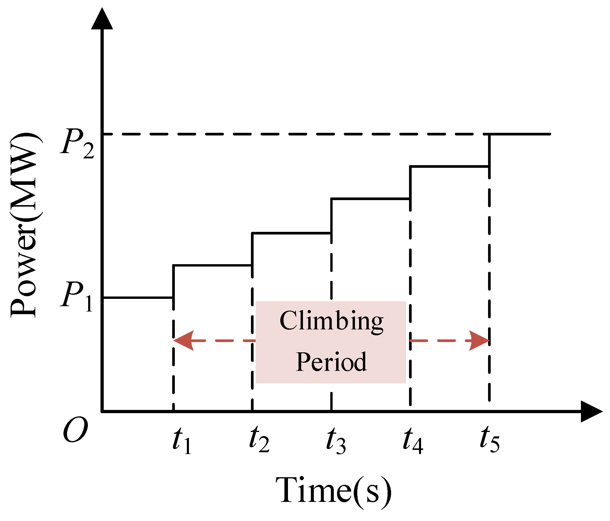
In the daily dispatch of the power system, thermal power units will inevitably adjust their output in time due to the uncertainty of renewable energy and load demand. However, due to their own characteristics, thermal power units are unable to respond quickly, so the impact caused by the ramp rate must be considered in the dispatching process. It has a maximum value of active power adjustment in a fixed time (generally 15 min) and different ramp rates for thermal power units with different parameters. Based on the unit historical data, the ramp rate is nonlinear, and the unit ramp rate can be verified by segmental linearization and estimation with a large amount of historical data. Here, it is assumed that the ramp rate of different units is constant, that is, Δ P ( MW ) / min is a setting value [32]. Then, the active power change of the unit during the climbing process is shown in Figure 3. The unit starts the climbing phase with the active power P 1 at time t 1 , reaches the active power P 2 at time t 5 , and ends the ramping process.

3.2. Improved Consensus Algorithm Considering the Ramp Climbing Rate

3.2.1. Graph Theoretical Foundation

The undirected graph G = ( V , E ) contains the set of nodes V = { 1 , , n } and the set of edges E V × V . When node i can communicate with other neighboring nodes, it can be represented as N i = { j V : ( j , i ) E } . Since G is an undirected graph and nodes i and j are adjacent and can communicate with each other, ( i , j ) E and ( j , i ) E represent the same meaning. A = ( a i j ) denotes the weighted adjacency matrix of graph G , where a i j = 1 when there is communication between i , j ; otherwise, a i j = 0 . Matrix D = d i a g { d i , i V } , d i = i N a i j represents the sum of the elements of row i of matrix A , that is, the entry degree of i . L = D A is the Laplacian matrix of graph G . The elements l i j of the matrix are as follows:
l i j = { a i j , j i j = 1 N a i j , j = i ,

3.2.2. Consensus Algorithm

The state quantity of node i is denoted by x i . Then, when the state quantities of all nodes are equal, it means that all nodes in the network have reached agreement and achieved consistency, that is, x 1 = x 2 = = x n . When the measurement information is obtained at a fixed time, the dynamic characteristics of the network can be described by a discrete-time dynamic system. The discrete consensus algorithm can be expressed as
x i [ k + 1 ] = j = 1 n d i j x j [ k ] , i = 1 , , n ,
where k is the sequence of discrete times, d i j is the element of the i - th row and j - th column of the row random matrix D , and d i j can be expressed as
d i j = | l i j | j = 1 n | l i j | , i = 1 , , n

3.2.3. Consensus Algorithm for Power System Scheduling

Suppose there are m power stations and n energy storage plants in a regional grid with cost consumption characteristics of F 1 ( P G 1 ) , F 1 ( P G 2 ) , , F 1 ( P G m ) and F 2 ( P B ( m + 1 ) ) , F 2 ( P B ( m + 2 ) ) , , F 2 ( P B ( m + n ) ) , respectively, and the total system load is P D . To achieve optimal economic operation, the power generation units need to be properly allocated, that is, after satisfying
i = 1 m P G i + k = m + 1 m + n P B k P D = 0 ,
such that the objective function
F = i = 1 m F 1 ( P G i ) + k = m + 1 m + n F 2 ( P B k ) ,
is the minimum. Similar to the conventional iso-consumption incremental rate criterion for power plants, this paper solves for the combination of energy storage plants and power plants, but the essence is still a multivariate function to find the extreme value of the problem, so the Lagrange function is constructed to solve it. The constructed Lagrange function is as follows:
L = F λ ( i = 1 m P G i + k = m + 1 m + n P B k P D ) ,
where λ is the Lagrange multiplier.
The necessary conditions for the extreme value of a function are as follows:
L P G i = F P G i λ i , i = 1 , 2 , , m ,
L P B k = F P B k λ k , k = m + 1 , m + 2 , , m + n ,
λ i = λ k = F P G i = F P B k ,
The objective function is minimized when (9) is finally satisfied, that is, the generation cost is minimized at this time. In power systems, node voltage, node power, and the incremental cost of the agent corresponding to the node can be used to represent the state of the node. Due to the complexity of the system, centralized control may cause dispatchers to lose full control of the grid. Therefore, a distributed approach is used to schedule the individual agents for the purpose of coordination. Here, incremental cost λ can be selected as a consensus protocol. By synchronously updating the incremental cost value and the output power of the generator and energy storage battery, the incremental cost of all agents can finally be consistent to achieve optimal scheduling. In this way, each agent interacts with only the neighboring agents in each iteration, and the interaction contains only λ ( t ) and P ( t ) . The specific interaction process is shown in Figure 4.
The node state variable is x ( t ) = { λ ( t ) | λ ( t ) P ( t ) } , where λ ( t ) P ( t ) represents the change induced by λ ( t ) for P ( t ) , where λ ( t ) is obtained from (2), and P ( t ) is obtained from λ ( t ) updated after each communication by (7) and (8). The power error is used as the marker for the end of the algorithm during each iteration. The power error is as follows:
Δ P ( t ) = i = 1 m P G i ( t ) + k = m + 1 m + n P B k ( t ) P D ( t ) ,
When it reaches the specified range, the iteration ends, and if it does not reach the specified error range, the above steps are repeated until the optimal solution is found.

3.2.4. Improved Consensus Algorithm

In power systems, distributed scheduling is employed to reduce information redundancy. However, the consensus algorithm causes repeated communication between the individual agents during the solution process until the optimal solution is reached, which greatly increases the burden on the communication lines for emergency dispatch. Moreover, due to the ramp rate limitations of thermal units, they are unable to respond to dispatch requests quickly. Even though each agent can adjust the power value in time after each communication, the power balance of the whole system can be significantly disrupted when the consensus protocol is not satisfied, which is undoubtedly added to the problem for emergency dispatch.
Due to non-real-time data acquisition and transmission, the information acquisition cannot be instantaneous, so the discrete-time consensus algorithm is used. However, due to these problems, the consensus algorithm needs to be improved.
First, the communication band between each agent is set according to the different ramping rates of the unit, as shown in Figure 5 and Figure 6.
Since the ramp rate of each thermal power unit is different, it is necessary to ensure effective communication after any change in the state of any agent; therefore, the communication needs to be completed separately at the moments of t 3 , t 2 , etc.
Based on these communication results, the change in node state quantity should be as follows:
λ i [ t + z ] = j = 1 n d i j λ j [ t ] , i = 1 , , n ,
where t is the communication band time series, and z is the time interval of each series.
Second, each agent performs an internal algorithm based on the load information issued by the dispatch center and obtains an ideal value of P G i D e s i r e d , P B k D e s i r e d , and λ D e s i r e d , which satisfy the following conditions:
λ D e s i r e d = F / P G i D e s i r e d = F / P B k D e s i r e d , i = { 1 , 2 , , m } , k = { m + 1 , m + 2 , , m + n } ,
This operation is carried out based on receiving the agent topology information sent by the control center in advance. It is the ideal value after ignoring the unit ramp rate.
Finally, each agent communicates with the others according to the communication band, and each communication is the actual value of the unit power P G i ( t ) and the corresponding incremental cost value λ i ( t ) for each time period. The specific interaction process is shown in Figure 7.
Currently, the agent node state quantity changes to (13):
x i ( t ) = { P G i ( t ) | P G i ( t ) λ i ( t ) } , i = 1 , 2 , , m ,
where P G i ( t ) λ i ( t ) represents the change induced by P G i ( t ) for λ i ( t ) .
The energy storage power during the climbing process changes with the actual power of the thermal power unit to meet the power balance of the climbing process in real time and achieve the balance stability of the climbing process.
x k ( t ) = { P B k ( t ) | P G i ( t ) P B k ( t ) λ k ( t ) } , k = m + 1 , , m + n ,
Eventually, when ε = | λ i ( t ) λ k ( t ) | is less than the specified value, the communication stops, and the climbing ends.

4. Emergency Dispatch Model

4.1. Objective Function

In emergency dispatch, most of the dispatch is for material dispatch [26,27]. In the future grid, there are abundant resources allocated to each link, and in most cases, the system is faced with the problem of coordinating the allocation of resources. When there is a sudden scarcity of resources, emergency dispatching should be conducted as soon as possible to maintain stable system operation with guaranteed load demand. This means that effective measures need to be taken in the shortest possible time to minimize the impact of faults on the power system. This requires relying on the technical means of monitoring, communication, and control of the power system to obtain information, make dispatching decisions, and execute dispatching solutions as fast as possible [33,34,35].
The proposed method in Section 3 ensures that the system can be regulated autonomously, so the model for emergency dispatch only needs to minimize the cost of and pollution from the system during the adjustment process. The objective of this paper is to minimize operating and environmental costs:
min F = min ( γ i F 1 i + γ i F 2 + γ k F 3 k ) ,
where γ is the decision variable, γ = { 1 , i 0 , i , and γ = { 1 , k 0 , k . represent the set of units connected to the network, and represents the collection of energy storage connected to the network. When the power generation unit is connected to the grid, γ is taken as 1; otherwise, γ = 0 . F 1 is the generation cost of conventional thermal power units, F 2 is the pollution cost of conventional thermal power units, and F 3 is the battery degradation cost.

4.1.1. Generation Cost of Conventional Thermal Power Units

The cost function of thermal power units can be represented by a quadratic function [36].
F 1 = i = 1 m ( a i + b i P G i + c i P G i 2 ) ,
where a i , b i , and c i are the generation cost factors, and P G i is the generator output.

4.1.2. Pollution Cost of Conventional Thermal Power Units

The pollution emission function of thermal power units can be expressed as follows [36]:
F 2 = i = 1 m ( d i + e i P G i + f i P G i 2 ) ,
where d i , e i , and f i are generation pollution factors.

4.1.3. Battery Degradation Cost

Considering the battery usage and the degradation cost of energy storage, it is necessary to integrate these two factors when designing the energy storage system in order to achieve economy and efficiency [37,38,39]. Therefore, we consider the efficiency of the battery in addition to the original degradation cost and comprehensively model the energy storage system. The model is as follows:
F 3 = Z × k = m + 1 m + n [ ( 1 + C C b a t N c y c l e ) g k P B k 2 + ( 1 + C C b a t N c y c l e ) h k P B k ] s ,
where P B k is the energy storage battery charging and discharging power, C C b a t is the investment cost of the battery, N c y c l e is the number of life cycles of the battery, s is the currency exchange rate, and Z is the number of energy storage batteries.

4.2. Constraints

4.2.1. Thermal Power Unit Climbing Constraint

The climbing rate of thermal power units has a very large impact on the system, so climbing constraints must be considered in emergency dispatch:
P G i ( t ) P G i ( t 1 ) P G i , A s c P G i ( t 1 ) P G i ( t ) P G i , D e s c ,
where P G i ( t ) and P G i ( t 1 ) are the power values of the thermal unit at moments t and t 1 , respectively, and P G i , A s c and P G i , D e s c are the maximum values of the unit rise or fall during the interval moments, respectively.
As the climbing rate has a great negative impact on emergency scheduling, it needs to be studied in depth.

4.2.2. Minimum Start–Stop Time Constraint

When the units in the power system are started or stopped, it is necessary to consider the time interval and running time of the units. For each unit, it is required to comply with the minimum start–stop time interval and the minimum continuous running time to avoid damage to the unit equipment and adverse effects on the load regulation of the power system caused by too frequent start–stop operations. At the same time, the start–stop operation of the unit needs to consider the requirements of load demand and supply–demand balance of the power grid to ensure the stable operation of the power system and the controllability of the power quality.

4.2.3. Power Balance Constraint

Energy storage charging when there is a surplus of renewable energy is obtained as follows:
P w i n d ( t ) + P s o l a r ( t ) P D ( t ) P L ( t ) P P 2 G ( t ) P B ( t ) = 0 ,
where P w i n d ( t ) is the electric power generated by the wind unit, P s o l a r ( t ) is the electric power generated by the photovoltaic unit, P D ( t ) is the total load of the grid, P L ( t ) is the line loss, P P 2 G ( t ) is the electric power consumed by electricity to gas, and P B ( t ) represents the charging power of the energy storage battery.
Energy storage discharging when renewable energy is insufficient is calculated as follows:
i = 1 N P G i ( t ) + P w i n d ( t ) + P s o l a r ( t ) + P B ( t ) P D ( t ) P L ( t ) = 0 ,
where P B ( t ) is the discharging power of the energy storage battery, and N represents the number of thermal power units.
Here, the loss values are applied to the transmission loss model by introducing Kron’s loss formula [40]. Kron’s loss formula can be expressed as
P L ( t ) = i = 1 n j n P G i ( t ) B i j P G j ( t ) + i = 1 n B 0 i P G i ( t ) + B 00 ,
where B i j , B 0 i , and B 00 are coefficients in the B matrix, all calculated from the parameters of the line and the average daily operating state of the power system.

4.2.4. Generator Output Power Constraint

For the generator to operate stably, the upper and lower limits of the generator output should be constrained as follows:
P G i min P G i ( t ) P G i max ,
where P G i min is the lower limit of the generator output, and P G i max is the upper limit of the generator output.

4.2.5. Battery Output Power Constraint

The output power of the battery should be limited, as too much output power can lead to a short battery life, so there should be limits as follows:
P B k min P B k ( t ) P B k max ,
where P B k min and P B k max represent the minimum and maximum values of energy storage battery charging and discharging power, respectively.
Due to the intermittency of renewable energy, which can lead to a certain degree of imbalance between supply and demand, energy storage batteries, with their fast response and high performance, can play a critical role in power balancing.

4.2.6. Battery State of Charge (SOC) Constraint

Energy storage batteries play an increasingly important role in the power system and can be used to balance the power supply and demand imbalance. When using energy storage batteries, it is necessary to consider constraints such as capacity as well as charging and discharging efficiency [38]. These constraints limit the charging and discharging performance of energy storage batteries, and therefore, it is necessary to model and manage these constraints in mathematical models to ensure the reliability and economy of energy storage batteries in the power system.
S O C ( t ) = E ( t ) / B c a p a c i t y ,
S O C min S O C ( t ) S O C max ,
where E ( t ) represents the energy stored in the battery at the moment t , B c a p a c i t y is the capacity of the battery, and S O C min and S O C max are the minimum and maximum values of the battery charging state, respectively.

4.3. Solution Steps

For the algorithm to work properly, it is necessary to set up a leader that collects the total load demand P D for each time period. Here, the dispatch control center can be used in such a role, where the leader sends information to each agent to facilitate the internal algorithm operation of the agent, and each agent then communicates with the others to achieve algorithm convergence. The specific steps are as follows.
Step 1: Input system parameters, including wind power and PV output data, load demand data, generator cost parameters, pollution parameters, matrix loss factor, maximum generator power, energy storage battery parameters, etc.
Step 2: Calculate the adjacency matrix L and row random matrix D of the communication network.
Step 3: Derive communication bands and communication frequencies for interaction between agents according to the different rates of ramp of the units.
Step 4: The deviation ξ between the new energy output and load demand is calculated at the time of starting T = 1 . If ξ > 0 , then the source side is satisfied by the wind power and PV output to meet the load demand, and the excess power generated is stored by the storage battery and P2G for backup. If ξ < 0 , then the new energy cannot meet the load demand, and the thermal power unit and storage battery need to be activated to supplement the source side output. The ideal value of the output of each thermal unit P i Desired and the ideal value of the incremental cost λ Desired are also calculated.
Step 5: Calculate the incremental cost value λ i ( t ) of each unit according to (7). Adjust the output of the energy storage battery in real time according to (21). Calculate the incremental cost value λ k ( t ) for each energy storage plant as follows:
λ i = F 1 / P G i + F 2 / P G i , i = 1 , , m ,
λ k = F 3 / P B k , k = m + 1 , , m + n ,
Step 6: Calculate the deviation ε of λ i ( t ) and λ k ( t ) , and if ε = | λ i ( t ) λ k ( t ) | is less than the specified value μ , output the generator and energy storage output at this time.
Step 7: Calculate the actual value of power P G i ( t + z ) in the next period based on the communication band as follows:
P G i ( t + z ) = P G i ( t ) + z × v i ,
where v i is the ramp rate of unit i . Repeat Step 5 thereafter.
Step 8: Return to Step 4 when both the renewable energy output and load values change at the next moment, T = T + 1 .
By considering the unit ramp rate, the improved consensus algorithm of the solving procedure is shown in Figure 8.

5. Case Study

5.1. System Structure

The validity of the proposed method was tested and verified in the modified IEEE-30 bus system [41], as shown in Figure 9. Wind power stations and photovoltaic power stations are connected at nodes 3 and 10, respectively. Different energy storage plants are connected at nodes 3, 6, and 10, where the parameters of the energy storage batteries of different energy storage plants are different, and the specific parameters are shown in Table A1 in Appendix A. At the same time, considering the diversity of energy forms in the new power system, a P2G device and a micro gas turbine are added at nodes 3 and 6 to realize the coupling of the electric and natural gas systems. Additionally, the data and thermal unit parameters used are shown in Figure A1 and Table A2 in Appendix A, respectively.
The cyber system corresponding to the node system uses a one-to-one correspondence between communication nodes and physical nodes; the communication system is shown in Figure 10.

5.2. Algorithm Comparison

To validate the differences between the proposed method and the methods presented in reference [10], we conducted a test analysis on the system operation at 16:00 on the same day. Different algorithms were applied to analyze the processing results of energy storage, and the results are shown in Figure 11 and Figure 12.
Based on the results shown in Figure 11, it can be observed that the improved consistency algorithm proposed in this paper exhibits significant improvement compared to the algorithms presented in the literature, and it is capable of quickly responding to system resource demands in a short period of time. Furthermore, the trend of the energy storage output showing an initial increase followed by a decrease is due to the consideration of the problem of asynchronous resource response in emergency dispatch processes, by coordinating the changes in energy storage output to compensate for system power shortages. This point is also confirmed by the results shown in Figure 12.
In practical engineering, due to the ramping characteristics of thermal power units, they cannot respond quickly to sudden load demand increases or other emergencies. Through the improved consistency algorithm, real-time communication can be established between thermal power units and energy storage, to compensate for system power shortages during the ramping process of the units. This is very helpful for maintaining system power balance in a short period of time. The advantage of the improved consistency algorithm makes it suitable for handling intermittent renewable energy and sudden load increases during emergency dispatch, ensuring the stable and reliable operation of the system.

5.3. Results Analysis

To verify the effectiveness of the improved consensus dispatching method proposed in this paper and the rationality of combining thermal power units with energy storage to participate in dispatching, four cases are set up in this paper as follows:
Case 1: Without considering the ramp rate and disregarding the participation of energy storage in scheduling;
Case 2: Without considering the ramp rate but allowing for the participation of energy storage in scheduling;
Case 3: Considering the ramp rate but not the participation of energy storage in scheduling.
Case 4: Considering the ramp rate and allowing energy storage to participate in scheduling.
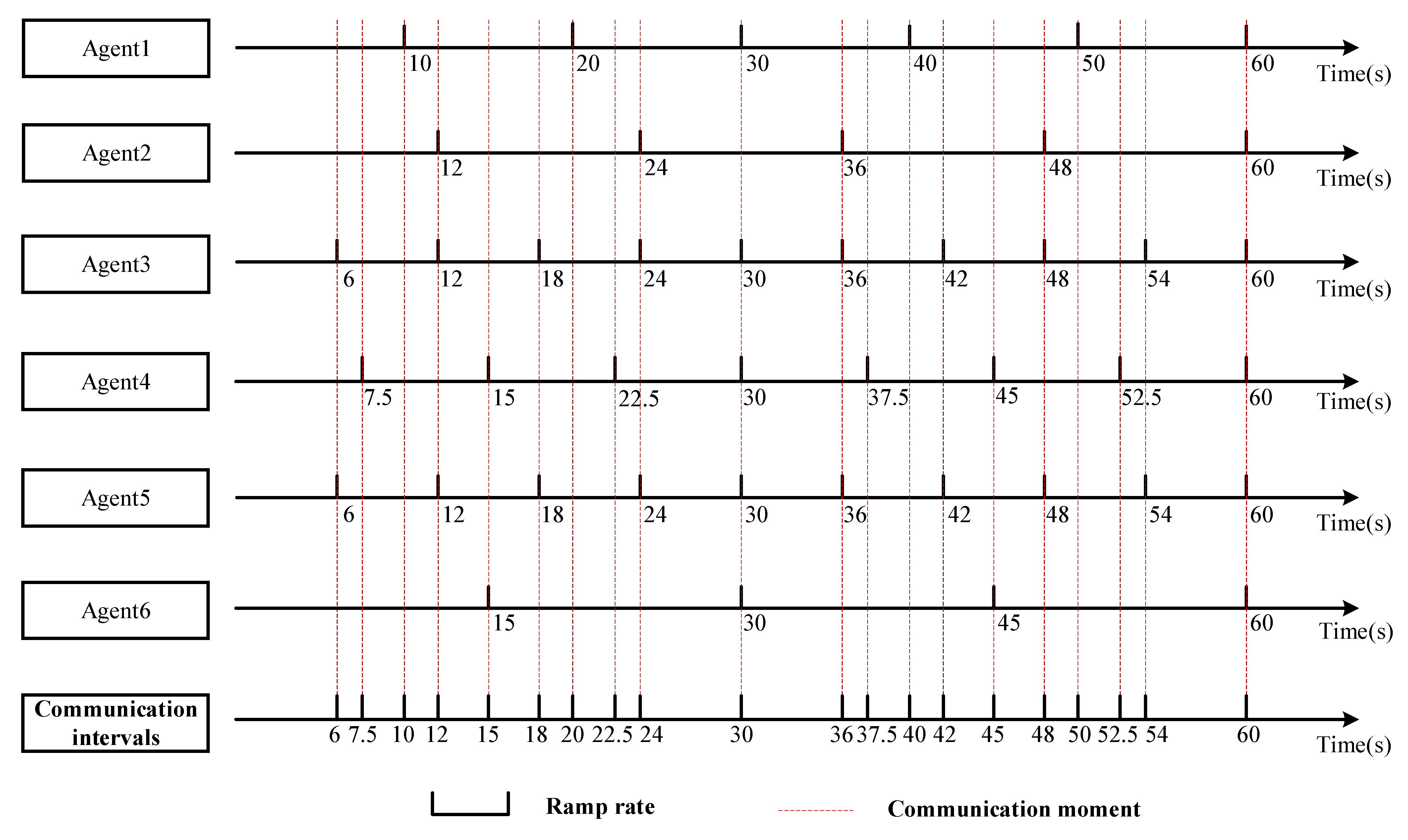
In this paper, the communication band was set according to the generator climbing parameters in Appendix A, and the results are shown in Figure A2 in Appendix B. According to the inter-constrained relationship of six units, the communication should be carried out in the order of 6 s, 7.5 s, and 10 s et al. after the start of dispatching, and the specific communication end mark depends on the actual unit status.

5.3.1. Test 1

Case 1: Without considering the ramp rate and disregarding the participation of energy storage in scheduling.
Without considering unit ramping and with no energy storage participation, the whole system can meet normal operation under ideal conditions. The unit output is shown in Figure 13. The output of all units of thermal power is zero during 0:00–6:00, 8:00–9:00, 10:00–11:00, and 12:00–13:00, at which time the new energy output has met the load demand. In other cases, the units need to receive commands to operate, and to ensure source-load coordination, they must be quickly started and run to the corresponding command value, which can be a serious challenge for thermal power units.
Figure 13c shows that if the surplus of renewable energy is not properly stored and utilized, it will result in a very serious waste of resources, which can reach 58.75% in the most serious case. Thus, in the development of new power systems, the rational application of renewable energy must be considered.

5.3.2. Test 2

Case 2: Without considering the ramp rate but allowing for the participation of energy storage in scheduling.
Without considering the ramp rate but allowing for energy storage, it is obvious from Figure 14 that the output of thermal power is significantly reduced, which is of great significance for the new power system to save energy and reduce emissions. The addition of energy storage can not only greatly ease the pressure on thermal power units but can also reduce pollution. In the process of energy storage operation, as in Figure 14, negative values appear due to the presence of surplus power generated by new energy generation in the system at this time. Especially during 1:00–2:00, it will not be able to store all the excess power at this time because the energy storage reaches the maximum input power. Then, P2G works to store the excess power in the form of natural gas, with 95.3 MW of power stored.

5.3.3. Test 3

Case 3: Considering the ramp rate but not the participation of energy storage in scheduling.
Considering the ramp rate but not the participation of energy storage in the dispatch, Figure 15 indicates that the output value of thermal units is still at a high level. Taking 7:00–8:00 as an example, the enlarged sub-diagram shows that when the unit changes from the previous time to the next time, the output value of the unit changes gradually. The whole process of unit climbing was completed in approximately 5 min according to the change in λ . The maximum power deviation of the system can be obtained by monitoring the real-time power situation of the system during ramp climb, which occurs at 7:00. The change in renewable energy output and load demand leads to extreme power imbalance, and due to the lack of energy storage at this time, such a situation cannot be handled and can only be filled slowly by waiting for the unit to climb, which is undoubtedly harmful to the system. As shown in Table A3 in Appendix B, such cases occur at all times and for variable durations.

5.3.4. Test 4

Case 4: Considering the ramp rate and allowing energy storage to participate in scheduling.
The results of Case 4 are shown in Figure 16. In considering the ramp rate and considering the participation of energy storage in scheduling, it is obvious that there will be many sudden changes in energy storage at the moment, which is to balance the difference between the supply and demand power of the system during the ramp climbing process of the unit. While meeting the load, energy storage can cooperate with the unit in real time to achieve the balance of system power, causing the system to remain stable.
For instance, at the initial moment of 7:00, the energy storage rapidly increases its own discharge power to a sufficient buffer time for the unit. Analyzing the comparison between Table A3 and Table A4 in Appendix B, the unit climbing time is nearly doubled compared to the case without energy storage participation, which is a very large improvement for daily dispatch and future emergency dispatch.
The four cases analyzed show that energy storage plays an important role in the system.
(1)
Storing excess renewable energy power and reducing the rate of wind (light) abandonment.
(2)
Participating in daily dispatching to reduce the generation output of thermal power units and reduce carbon emissions.
(3)
Smoothing out the system power imbalance caused by unit ramp climbing and maintaining system stability.
The proposed model presented in this paper enables the matching of energy storage and thermal power units and facilitates dispatching through autonomous communication. The improved consensus algorithm developed in this study is applied to scheduling tasks in the power system scheduling process. This approach not only meets the system demand but also ensures system stability during unit ramping.

5.4. Energy Distribution in Energy Storage Plants

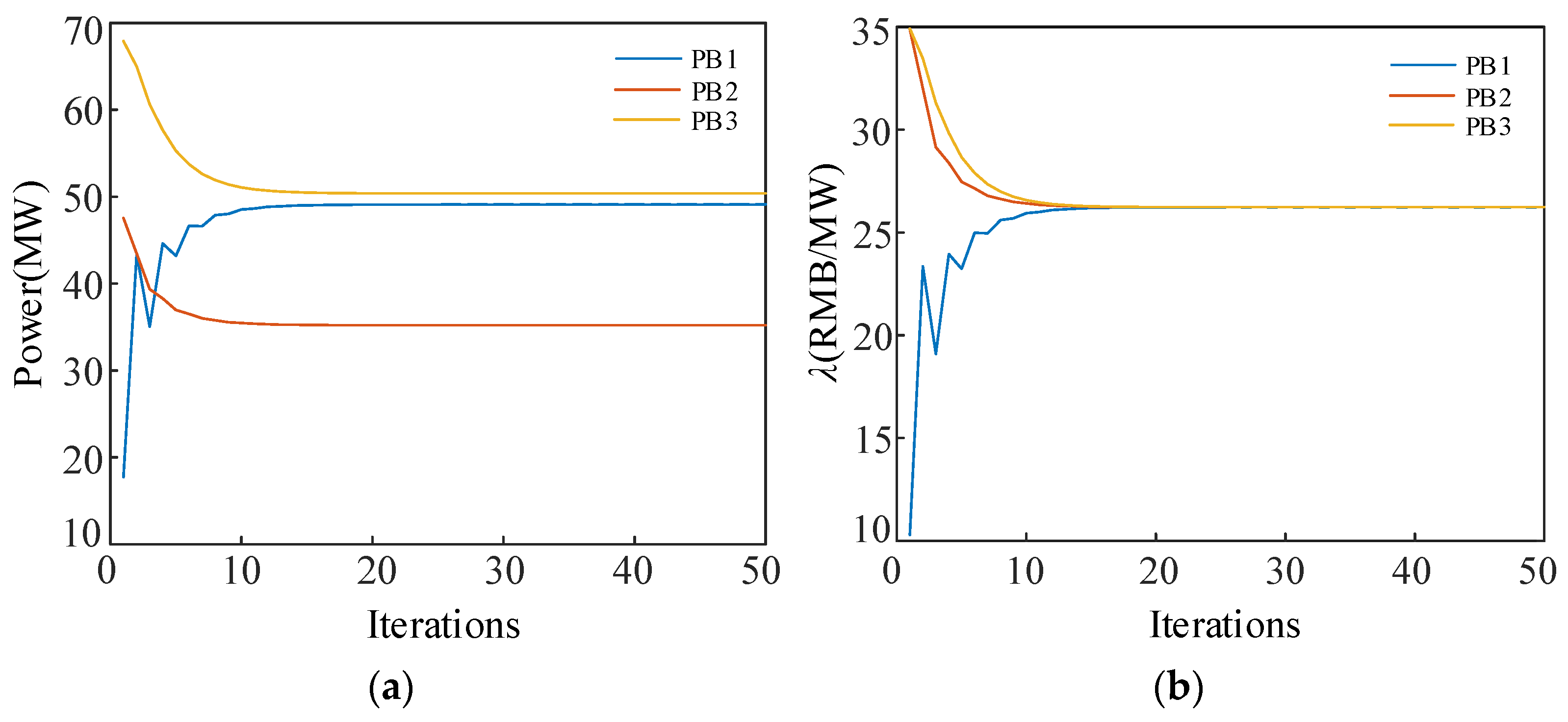
According to the results of 5.2, the system can meet the electrical energy demand of the load from 0:00 a.m. to 6:00 a.m. The excess power generated at this time needs to be stored by the energy storage device. Different parameters for different energy storage plants can affect the allocation results. This section allocates the energy storage based on the incremental cost of energy storage degradation as consistency, where the allocation results from 5:00 to 6:00 are shown in Figure 17.
Due to the rapid response of the energy storage battery, its climbing rate is not considered in this section. The distribution from the energy storage battery is completed based on the communication between energy storage plants, and the coherency agreement is calculated based on the consensus algorithm when climbing is not considered. Figure 17 suggests that good coherency convergence can be achieved for different types of energy storage batteries.

5.5. Emergency Dispatch

5.5.1. Test 1

Case: A cyber-attack on the communication layer causes damage to the agent 5 communication node.
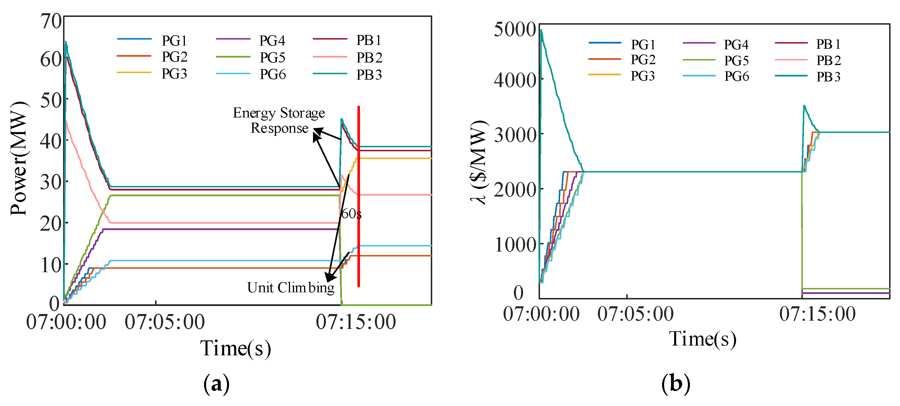
In the case of system emergencies, the system can achieve consistency based on the communication between agents. As shown in Figure 18, when the system is suddenly attacked by the cyber-attack at 7:15 and communication node 5 is disabled, the corresponding unit will also be temporarily withdrawn from the operation of the unit for safety reasons. Since node 4 in the communication network is only connected to node 5, node 5 causes the units in node 4 to lose communication with other agents as well, so for safety reasons, only four thermal units are working at the moment. Meanwhile, the energy storage battery action ensures that the system can maintain power balance in case of failure, making the load side less affected. Figure 18a shows that after nearly 1 min of communication, the whole system reaches a stable operating state. Therefore, the method proposed in this paper can make a rapid and efficient scheduling response to the failure in this case.

5.5.2. Test 2

Case: The output of the agent 4 unit is limited due to the unit’s own reason or the communication node encountering cyber-attacks.
Based on the test results, when the system unit is faced with a limited output, the unit can also be automatically adjusted. Since it was the unit output that was restricted, the dispatch time lasted only 12 s to complete the dispatch task. Figure 19b shows that the value of PG4 eventually no longer converges to the same value as the other agents as a result of the limited output of its own unit. The factors of one unit do not affect the convergence results of other units, and eventually a new system stability can be achieved.

5.5.3. Test 3

Case: Sudden high temperature causes a surge in load demand at a certain time.
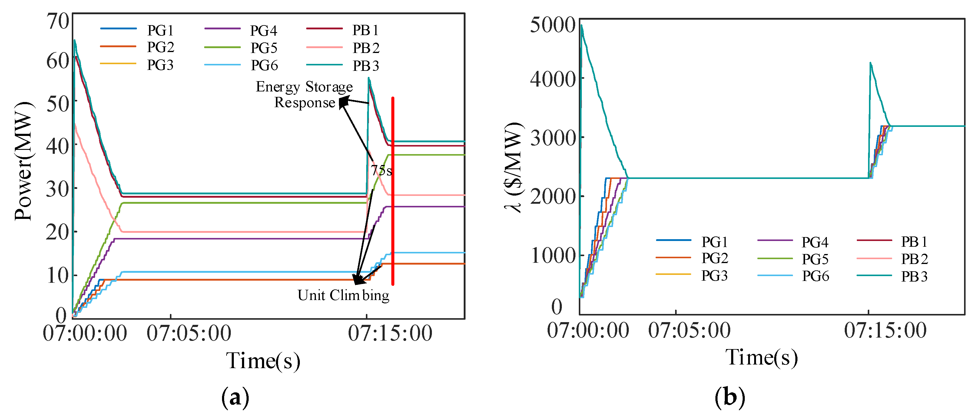
In the process of power system operation, a variety of natural environments will be encountered, of which the more typical is high-temperature weather. Due to the high-temperature weather, the frequency of using household appliances such as air conditioners has increased dramatically. In such cases, sudden demand growth on the load side can make operating the grid very challenging. Testing the methods in this paper suggest that in the event of a sudden surge in load, energy storage will play a huge role in a short period of time due to the climbing constraint of the unit. The findings are depicted in Figure 20. It also suggests that when the load suddenly surges, the energy storage will play a great role in a short period of time due to the unit’s climbing constraint, which can provide sufficient response time for the unit to climb. While the load is surging, the energy storage and the unit increase their output together, the energy storage greatly relieves the pressure of thermal power units.
These results indicate that when an emergency event occurs in the power system, the model proposed in this paper can be used to achieve coordinated cooperation between energy storage and thermal power units. This reduces system carbon emissions while relieving pressure on thermal power units. In emergency dispatch, after considering the unit ramp climbing rate, the system achieves system power balance in the ramp climbing process through energy storage during autonomous dispatch communication.

6. Conclusions

To address the high volatility and uncertainty in future power systems that incorporate hybrid energy sources, energy storage is introduced as a flexible resource for joint optimization with thermal power units, providing supplementary support to the grid through distributed control. To tackle power imbalance issues stemming from varying response rates in emergency scheduling, the consensus algorithm is enhanced. Based on this approach, several key findings are obtained.
(1)
Taking into account the degradation cost of energy storage, it can be optimized jointly with thermal units to achieve consistent incremental costs and enable local autonomous communication between agents.
(2)
Energy storage, as a flexible resource, provides a very strong flexibility enhancement to the power system. There is a growing need to integrate more flexible resources into the system in order to cope with the increasing uncertainty of the grid.
(3)
By considering the ramp rate of thermal power units, resetting the communication intervals can solve the power imbalance problem of the consensus algorithm during emergency dispatch in the system.
(4)
Experimental analysis shows that using the improved consensus algorithm can ensure the reasonable allocation of resources during emergency dispatching in the system, enabling the tested system in this paper to achieve the effect of emergency disposal in about 10 s~150 s and ensure power balance within this period, thereby improving the flexibility and reliability of the system operation.
As P2G technology is widely applied in future energy systems, the coupling among natural gas, thermal energy, and electricity will become even tighter, which will make the energy system face more network attacks and security threats. Therefore, ensuring the coordination and scheduling of various energy sources during emergency situations will become a more critical issue. To achieve this, it is necessary to introduce more secure and reliable communication and control technologies in the future, to achieve real-time communication and coordination scheduling among various energy devices, in order to ensure the safe, reliable, and stable operation of the energy system.
At the same time, it is also necessary to strengthen the security evaluation and monitoring of the energy system, as well as to promptly detect and deal with various security threats, in order to ensure the normal operation of the energy system and the safety of users’ electricity.

Author Contributions

Conceptualization, B.Z. and T.Z.; methodology, J.W. and Y.C.; software, J.W. and B.S.; validation, B.Z., J.W. and T.Z.; formal analysis, J.W. and T.Z.; investigation, J.W. and Y.C.; resources, J.W. and B.S.; data curation, J.W. and Y.Q.; writing—original draft preparation, B.Z., J.W. and T.Z.; writing—review and editing, B.Z., J.W., T.Z. and Y.Q.; visualization, T.Z. and J.W.; supervision, B.Z. and T.Z.; project administration, T.Z. and B.Z.; funding acquisition, T.Z. All authors have read and agreed to the published version of the manuscript.

Funding

This work was supported in part by National Science Foundation of China (No. 51907097) and National Key R&D Program of China (No. 2021YFB4000500).

Data Availability Statement

Not applicable.

Conflicts of Interest

The authors declare no conflict of interest.

Appendix A

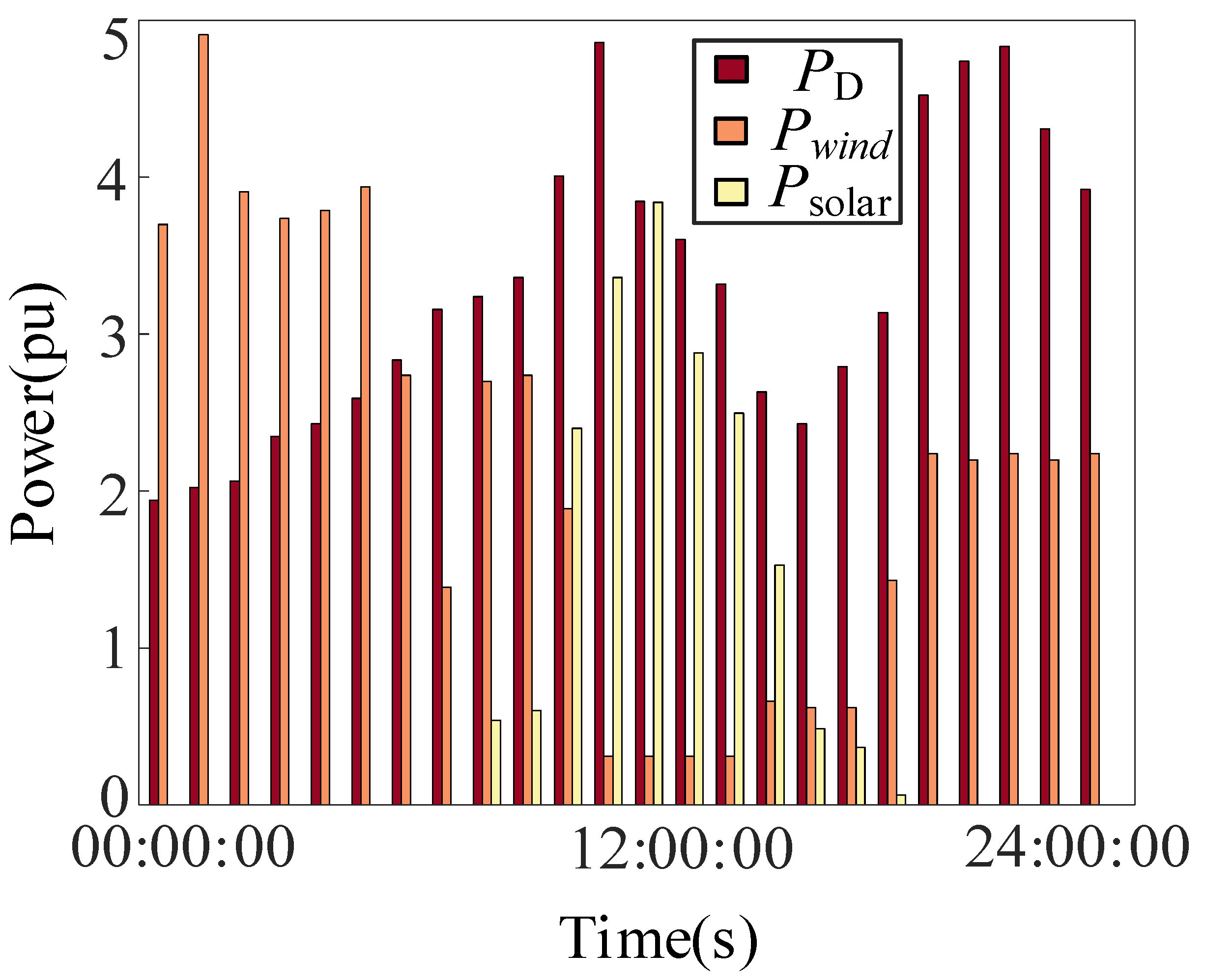
Figure A1 shows the load and renewable energy data used in this paper, with a baseline value of 100 MW.
Figure A1. Load and renewable energy data.
Energies 16 04213 g0a1
The B-coefficient matrix used to represent the line loss of a 30_bus system is shown below.
B = [ 0.1382 0.0299 0.0044 0.0022 0.0010 0.0008 0.0299 0.0487 0.0025 0.0004 0.0016 0.0041 0.0044 0.0025 0.0182 0.0070 0.0066 0.0066 0.0022 0.0004 0.0070 0.0137 0.0050 0.0033 0.0010 0.0016 0.0066 0.0050 0.0109 0.0005 0.0008 0.0041 0.0066 0.0033 0.0005 0.0244 ] B 0 = [ 0.0107 0.0060 0.0017 0.0009 0.0002 0.0030 ] Β 00 = 0.00098573
Table A1. Energy storage parameters.
Energy Storage Power StationAgentLocationhg P B k min P B k max N c y c l e C C b a t (RMB) Number of Batteries
PB1Agent731.04600.2037−6060500012301000
PB2Agent861.23090.2815−6065
PB3Agent9101.02920.1987−6068
Table A2. Generator parameters.
GeneratorAgentLocationabcdefClimbing Rate (MW/min)
PG1Agent151015012013.859320.327670.004196
PG2Agent2111015012013.859320.327670.004195
PG3Agent31201804040.2669−0.545510.0068310
PG4Agent48101006040.2669−0.545510.006838
PG5Agent52201804042.89553−0.511160.0046110
PG6Agent6131015010042.89553−0.511160.004614

Appendix B

Table A3. Duration of power imbalance at different time periods in Case 3.
Time Period6:00–7:007:00–8:008:00–9:0011:00–12:0012:00–13:0013:00–14:0014:00–15:0015:00–16:00
Duration18 s270 s277 s195 s187 s67 s20 s18 s
Time Period16:00–17:0017:00–18:0018:00–19:0019:00–20:0020:00–21:0021:00–22:0022:00–23:0023:00–24:00
Duration156 s80 s30 s108 s48 s15 s78 s72 s
Table A4. Duration of power imbalance at different time periods in Case 4.
Time Period7:00–8:008:00–9:0011:00–12:0012:00–13:0013:00–14:0014:00–15:0016:00–17:0017:00–18:00
Duration179 s156 s110 s108 s37 s10 s80 s45 s
Time Period18:00–19:0019:00–20:0020:00–21:0022:00–23:0023:00–24:00
Duration20 s66 s20 s45 s45 s
Figure A2. Actual communication intervals of 6 units.
Energies 16 04213 g0a2

References

  1. Elnady, A.; Noureldin, A.; Adam, A.A. Improved Synergetic Current Control for Grid-connected Microgrids and Distributed Generation Systems. J. Mod. Power Syst. Clean Energy 2022, 10, 1302–1313. [Google Scholar] [CrossRef]
  2. Smil, V. Distributed Generation and Megacities: Are Renewables the Answer? IEEE Power Energy Mag. 2019, 17, 37–41. [Google Scholar] [CrossRef]
  3. Xu, J.; Xie, B.; Liao, S.; Yuan, Z.; Ke, D.; Sun, Y.; Li, X.; Peng, X. Load Shedding and Restoration for Intentional Island with Renewable Distributed Generation. J. Mod. Power Syst. Clean Energy 2021, 9, 612–624. [Google Scholar] [CrossRef]
  4. Shi, X.; Li, Y.; Cao, Y.; Tan, Y. Cyber-physical electrical energy systems: Challenges and issues. CSEE J. Power Energy Syst. 2015, 1, 36–42. [Google Scholar] [CrossRef]
  5. Qin, B.; Liu, D. Research Progresses and Prospects on Analysis and Control of Cyber-physical System for Power Grid. Proc. Chin. Soc. Electr. Eng. 2020, 40, 5816–5827. [Google Scholar] [CrossRef]
  6. Mahela, O.P.; Khosravy, M.; Gupta, N.; Khan, B.; Alhelou, H.H.; Mahla, R.; Patel, N.; Siano, P. Comprehensive overview of multi-agent systems for controlling smart grids. CSEE J. Power Energy Syst. 2022, 8, 115–131. [Google Scholar] [CrossRef]
  7. Gomes, L.; Faria, P.; Morais, H.; Vale, Z.; Ramos, C. Distributed, Agent-Based Intelligent System for Demand Response Program Simulation in Smart Grids. IEEE Intell. Syst. 2014, 29, 56–65. [Google Scholar] [CrossRef]
  8. Hernandez, L.; Baladron, C.; Aguiar, J.M.; Carro, B.; Sanchez-Esguevillas, A.; Lloret, J.; Chinarro, D.; Gomez-Sanz, J.J.; Cook, D. A multi-agent system architecture for smart grid management and forecasting of energy demand in virtual power plants. IEEE Commun. Mag. 2013, 51, 106–113. [Google Scholar] [CrossRef]
  9. Hu, J.; Cong, H.; Jiang, C. Coordinated scheduling model of power system with active distribution networks based on multi-agent system. J. Mod. Power Syst. Clean Energy 2018, 6, 521–531. [Google Scholar] [CrossRef]
  10. Kar, S.; Hug, G. Distributed robust economic dispatch in power systems: A consensus + innovations approach. In Proceedings of the 2012 IEEE Power and Energy Society General Meeting, San Diego, CA, USA, 22–26 July 2012; pp. 1–8. [Google Scholar]
  11. Xing, H.; Mou, Y.; Fu, M.; Lin, Z. Distributed algorithm for economic power dispatch including transmission losses. In Proceedings of the 2015 European Control Conference (ECC), Linz, Austria, 15–17 July 2015; pp. 1076–1081. [Google Scholar]
  12. Lyu, Z.; Yang, X.; Zhang, Y.; Zhao, J. Bi-Level Optimal Strategy of Islanded Multi-Microgrid Systems Based on Optimal Power Flow and Consensus Algorithm. Energies 2020, 13, 1537. [Google Scholar] [CrossRef]
  13. Zhang, M.; Wang, G.; Shi, C.; Huang, M. Distributed Economic Dispatch for Power Systems Considering Communication Noise. Power Syst. Technol. 2017, 41, 2293–2300. [Google Scholar] [CrossRef]
  14. Zhang, Z.; Shang, L.; Liu, C.; Lai, Q.; Jiang, Y. Consensus-based distributed optimal power flow using gradient tracking technique for short-term power fluctuations. Energy 2023, 264, 125635. [Google Scholar] [CrossRef]
  15. Ullah, M.H.; Alseyat, A.; Park, J.-D. Multi-Agent System-based Distributed Energy Management in Smart Grid under Uncertainty. In Proceedings of the 2019 IEEE Energy Conversion Congress and Exposition (ECCE), Baltimore, MD, USA, 29 September–3 October 2019; pp. 3462–3468. [Google Scholar]
  16. Liao, W.; Li, P.; Wu, Q.; Huang, S.; Wu, G.; Rong, F. Distributed optimal active and reactive power control for wind farms based on ADMM. Int. J. Electr. Power Energy Syst. 2021, 129, 106799. [Google Scholar] [CrossRef]
  17. Chang, X.; Xu, Y.; Sun, H.; Khan, I. A distributed robust optimization approach for the economic dispatch of flexible resources. Int. J. Electr. Power Energy Syst. 2021, 124, 106360. [Google Scholar] [CrossRef]
  18. Arévalo, P.; Tostado-Véliz, M.; Jurado, F. A novel methodology for comprehensive planning of battery storage systems. J. Energy Storage 2021, 37, 102456. [Google Scholar] [CrossRef]
  19. Zhang, B.; Wang, J.; Liang, D.; Han, X. Optimization Control Strategy of Distributed Energy Storage in Autonomous Microgrid Cluster on Consensus Algorithm. Power Syst. Technol. 2020, 44, 1705–1713. [Google Scholar] [CrossRef]
  20. Yang, H.; Yin, L.; Li, Q.; Chen, W.; Zhou, L. Multiagent-Based Coordination Consensus Algorithm for State-of-Charge Balance of Energy Storage Unit. Comput. Sci. Eng. 2018, 20, 64–77. [Google Scholar] [CrossRef]
  21. Alan, J. SANGSTER Massive energy storage systems enable secure electricity supply from renewables. J. Mod. Power Syst. Clean Energy 2016, 4, 659–667. [Google Scholar] [CrossRef]
  22. Zhao, D.; Xu, C.; Tao, R.; Zheng, Y. Review on Flexible Regulation of Multiple Distributed Energy Storage in Distribution Side of New Power System. Proc. Chin. Soc. Electr. Eng. 2023, 43, 1776–1799. [Google Scholar] [CrossRef]
  23. Li, B.; Chen, M.; Zhong, H.; Ma, Z.; Liu, D. A Review of Long-term Planning of New Power Systems with Large Share of Renewable Energy. Proc. Chin. Soc. Electr. Eng. 2023, 43, 555–581. [Google Scholar] [CrossRef]
  24. Lei, S.; Wang, J.; Chen, C.; Hou, Y. Mobile Emergency Generator Pre-Positioning and Real-Time Allocation for Resilient Response to Natural Disasters. IEEE Trans. Smart Grid 2018, 9, 2030–2041. [Google Scholar] [CrossRef]
  25. Jiang, S.; Zhao, X.; Pan, G.; Gao, S.; Wu, C.; Liu, Y.; Wang, S. A novel robust frequency-constrained unit commitment model with emergency control of HVDC. Energy Rep. 2022, 8, 15729–15739. [Google Scholar] [CrossRef]
  26. Qin, Z.; Chen, X.; Hou, Y.; Liu, H.; Yang, Y. Coordination of Preventive, Emergency and Restorative Dispatch in Extreme Weather Events. IEEE Trans. Power Syst. 2022, 37, 2624–2638. [Google Scholar] [CrossRef]
  27. Deng, C.; Liu, Y.; Tan, Y.; Yu, X.; Liu, J.; Li, H. Emergency Power Resource Dispatching Considering Procedure of Power Grid Restoration. Dianwang JishuPower Syst. Technol. 2017, 41, 3582–3589. [Google Scholar] [CrossRef]
  28. Zuo, F.; Zhang, Y.; Zhao, Q.; Sun, L. Two-stage Stochastic Optimization for Operation Scheduling and Capacity Allocation of Integrated Energy Production Unit Considering Supply and Demand Uncertainty. Proc. CSEE 2022, 42, 8205–8215. [Google Scholar] [CrossRef]
  29. Zhu, X.; Luo, J.; Lin, Z.; Yao, X.; Liu, M. Low-carbon economic dispatching of energy hub considering flexible ramping product. Electric Power Automation Equipment. Electr. Power Autom. Equip. 2023, 43, 9–15+24. [Google Scholar] [CrossRef]
  30. Xu, H.; Li, H. Planning and Operation Stochastic Optimization Model of Power Systems Considering the Flexibility Reformation. Power Syst. Technol. 2020, 44, 4626–4638. [Google Scholar] [CrossRef]
  31. Yan, S.; Wang, W.; Li, X.; Fan, T. Cross-regional Flexible Robust Optimal Scheduling in Dynamic Economic Environment with Joint Frequency Regulation of Energy Storage and Units. Autom. Electr. Power Syst. 2022, 46, 61–70. [Google Scholar]
  32. Yang, L.; Zhou, N.; Hu, B.; Chen, L.; Xu, F. Optimal Scheduling Method for Coupled System Based on Ladder-type Ramp Rate of Thermal Power Units. Proc. Chin. Soc. Electr. Eng. 2022, 42, 153–164. [Google Scholar] [CrossRef]
  33. Qiu, T.; Zheng, K.; Song, H.; Han, M.; Kantarci, B. A Local-Optimization Emergency Scheduling Scheme With Self-Recovery for a Smart Grid. IEEE Trans. Ind. Inform. 2017, 13, 3195–3205. [Google Scholar] [CrossRef]
  34. Wang, C.; Deng, D.; Xu, L.; Wang, W. Resource Scheduling Based on Deep Reinforcement Learning in UAV Assisted Emergency Communication Networks. IEEE Trans. Commun. 2022, 70, 3834–3848. [Google Scholar] [CrossRef]
  35. Cao, X.; Cao, T.; Xu, Z.; Zeng, B.; Gao, F.; Guan, X. Resilience Constrained Scheduling of Mobile Emergency Resources in Electricity-Hydrogen Distribution Network. IEEE Trans. Sustain. Energy 2023, 14, 1269–1284. [Google Scholar] [CrossRef]
  36. Bayon, L.; Grau, J.M.; Ruiz, M.M.; Suarez, P.M. The Exact Solution of the Environmental/Economic Dispatch Problem. IEEE Trans. Power Syst. 2012, 27, 723–731. [Google Scholar] [CrossRef]
  37. Garcia-Torres, F.; Bordons, C. Optimal Economical Schedule of Hydrogen-Based Microgrids With Hybrid Storage Using Model Predictive Control. IEEE Trans. Ind. Electron. 2015, 62, 5195–5207. [Google Scholar] [CrossRef]
  38. Elkazaz, M.; Sumner, M.; Naghiyev, E.; Pholboon, S.; Davies, R.; Thomas, D. A hierarchical two-stage energy management for a home microgrid using model predictive and real-time controllers. Appl. Energy 2020, 269, 115118. [Google Scholar] [CrossRef]
  39. Choi, J.-Y.; Choi, I.-S.; Ahn, G.-H.; Won, D.-J. Advanced Power Sharing Method to Improve the Energy Efficiency of Multiple Battery Energy Storages System. IEEE Trans. Smart Grid 2018, 9, 1292–1300. [Google Scholar] [CrossRef]
  40. Gong, D.; Zhang, Y.; Qi, C. Environmental/economic power dispatch using a hybrid multi-objective optimization algorithm. Int. J. Electr. Power Energy Syst. 2010, 32, 607–614. [Google Scholar] [CrossRef]
  41. Sawas, A.M.; Khani, H.; Farag, H.E.Z. On the Resiliency of Power and Gas Integration Resources Against Cyber Attacks. IEEE Trans. Ind. Inform. 2021, 17, 3099–3110. [Google Scholar] [CrossRef]
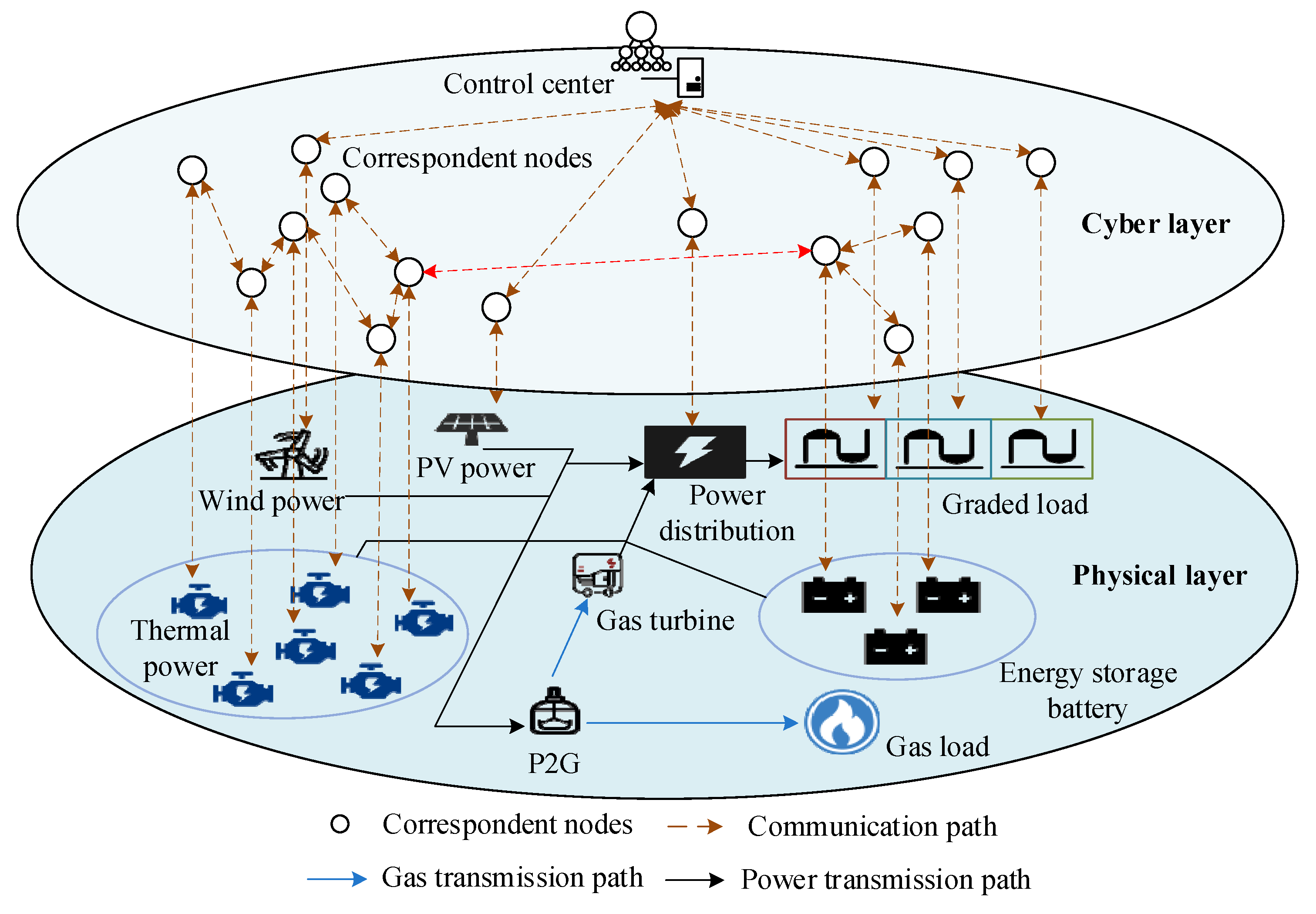
Figure 1. Power system with hybrid energy under cyber-physical coupling.
Energies 16 04213 g001
Figure 2. General framework diagram.
Energies 16 04213 g002
Figure 3. Schematic diagram of the climbing process of the unit.
Energies 16 04213 g003
Figure 4. Interaction process between agents.
Energies 16 04213 g004
Figure 5. Multiagent system.
Energies 16 04213 g005
Figure 6. Communication band based on ramp rate.
Energies 16 04213 g006
Figure 7. Improved interaction processes between agents.
Energies 16 04213 g007
Figure 8. Flowchart of the proposed algorithm.
Energies 16 04213 g008
Figure 9. Schematic diagram of the modified IEEE-30 bus system.
Energies 16 04213 g009
Figure 10. Communication system.
Energies 16 04213 g010
Figure 11. (a) The output results of PB1 using two different algorithms; (b) the output results of PB2 using two different algorithms; (c) the output results of PB3 using two different algorithms.
Energies 16 04213 g011
Figure 12. (a) Incremental cost values λ of PB1 using two different algorithms; (b) incremental cost values λ of PB2 using two different algorithms; (c) incremental cost values λ of PB3 using two different algorithms.
Energies 16 04213 g012
Figure 13. Result diagram of Case 1. (a) Diagram of thermal power output results; (b) schematic diagram of the variation of λ ; (c) abandoned wind (light) rate of the system.
Energies 16 04213 g013
Figure 14. Diagram of thermal power and energy storage output results.
Energies 16 04213 g014
Figure 15. Result diagram of Case 3. (a) Diagram of thermal power output results; (b) schematic diagram of the variation of λ ; (c) partial power imbalance diagram.
Energies 16 04213 g015
Figure 16. Result diagram of Case 4. (a) Diagram of thermal power output results; (b) diagram of energy storage output results; (c) schematic diagram of the variation of λ .
Energies 16 04213 g016
Figure 17. (a) Diagram of energy storage charging results; (b) the variation of λ .
Energies 16 04213 g017
Figure 18. Results diagram of Test 1. (a) Diagram of dispatching results; (b) schematic diagram of variation of λ .
Energies 16 04213 g018
Figure 19. Results diagram of Test 2. (a) Diagram of dispatching results; (b) schematic diagram of the variation of λ .
Energies 16 04213 g019
Figure 20. Results diagram of Test 3. (a) Diagram of dispatching results; (b) schematic diagram of the variation of λ .
Energies 16 04213 g020
Disclaimer/Publisher’s Note: The statements, opinions and data contained in all publications are solely those of the individual author(s) and contributor(s) and not of MDPI and/or the editor(s). MDPI and/or the editor(s) disclaim responsibility for any injury to people or property resulting from any ideas, methods, instructions or products referred to in the content.