
Analytical Modeling, Analysis and Diagnosis of External Rotor PMSM with Stator Winding Unbalance Fault

Abstract
1. Introduction
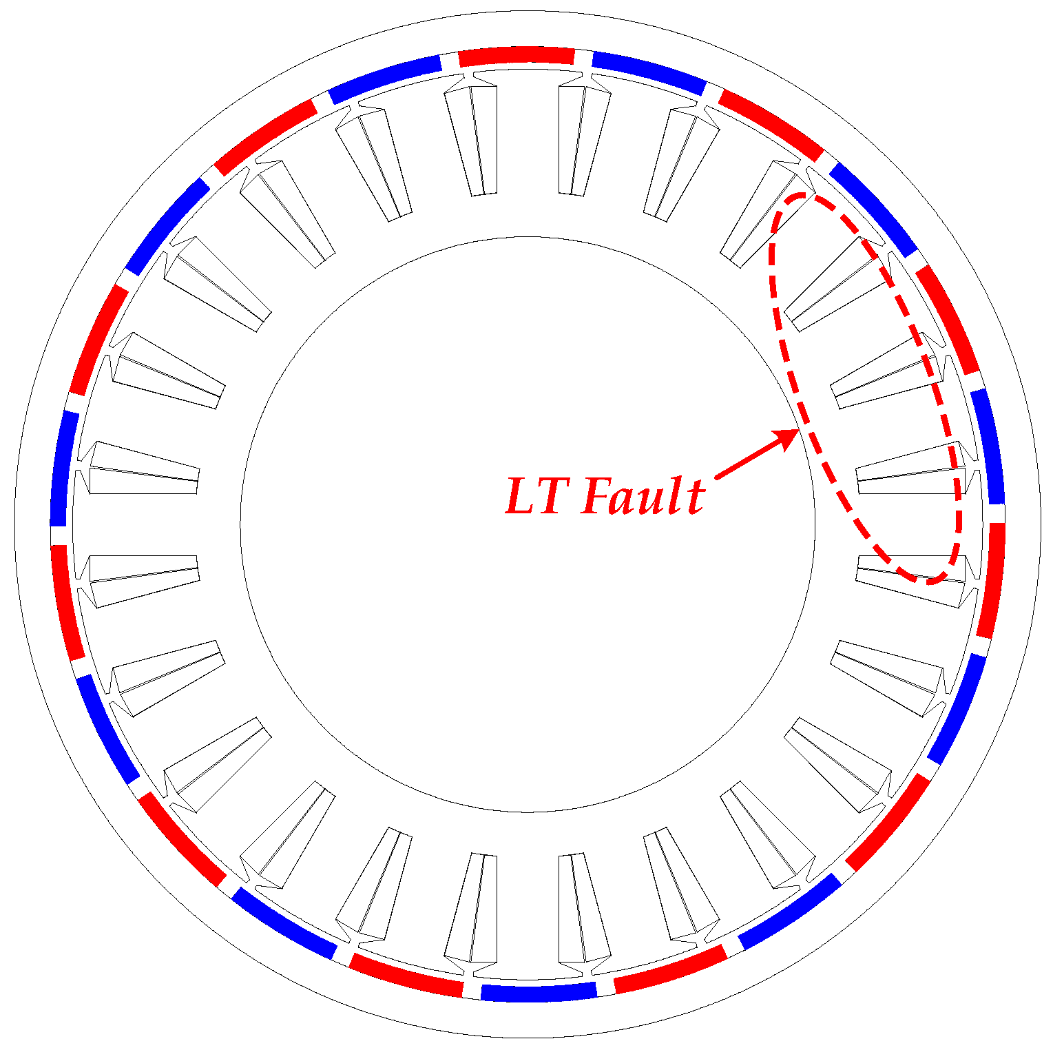
2. Exhaustive Analysis of LTs Fault
- (1)
- Magnetic saturation is negligible;
- (2)
- Ideal ferromagnetic steel and the magnetic energy is concentrated in the air-gap;
- (3)
- Small air-gap relative to the internal diameter of the stator and radial magnetic field (tangential magnetic fields are negligible);
- (4)
- Neglected conductivity and eddy current effects.
2.1. Analytical Approach
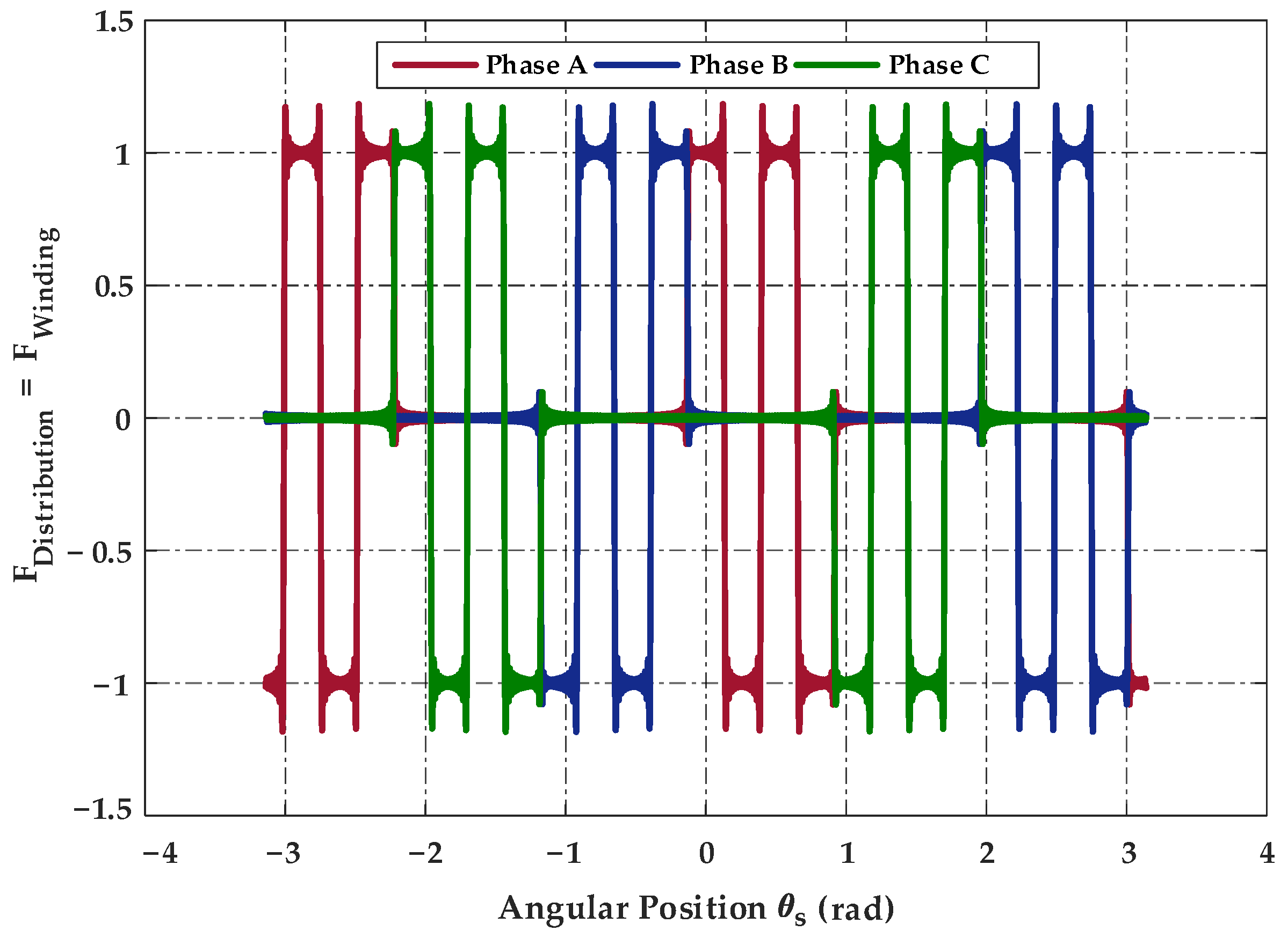
2.1.1. Distribution Function of the ER-PMSM
2.1.2. Winding Function of the ER-PMSM
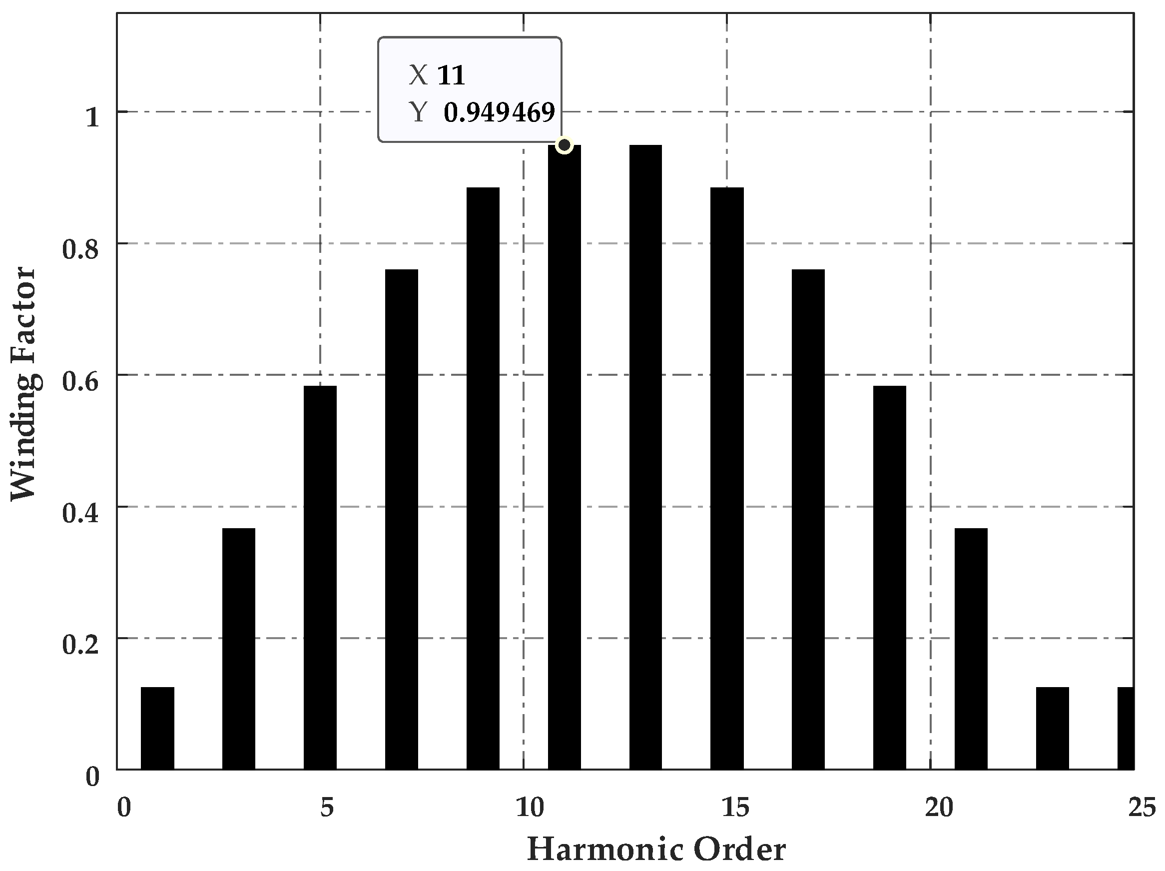
2.1.3. Winding Factor of the ER-PMSM
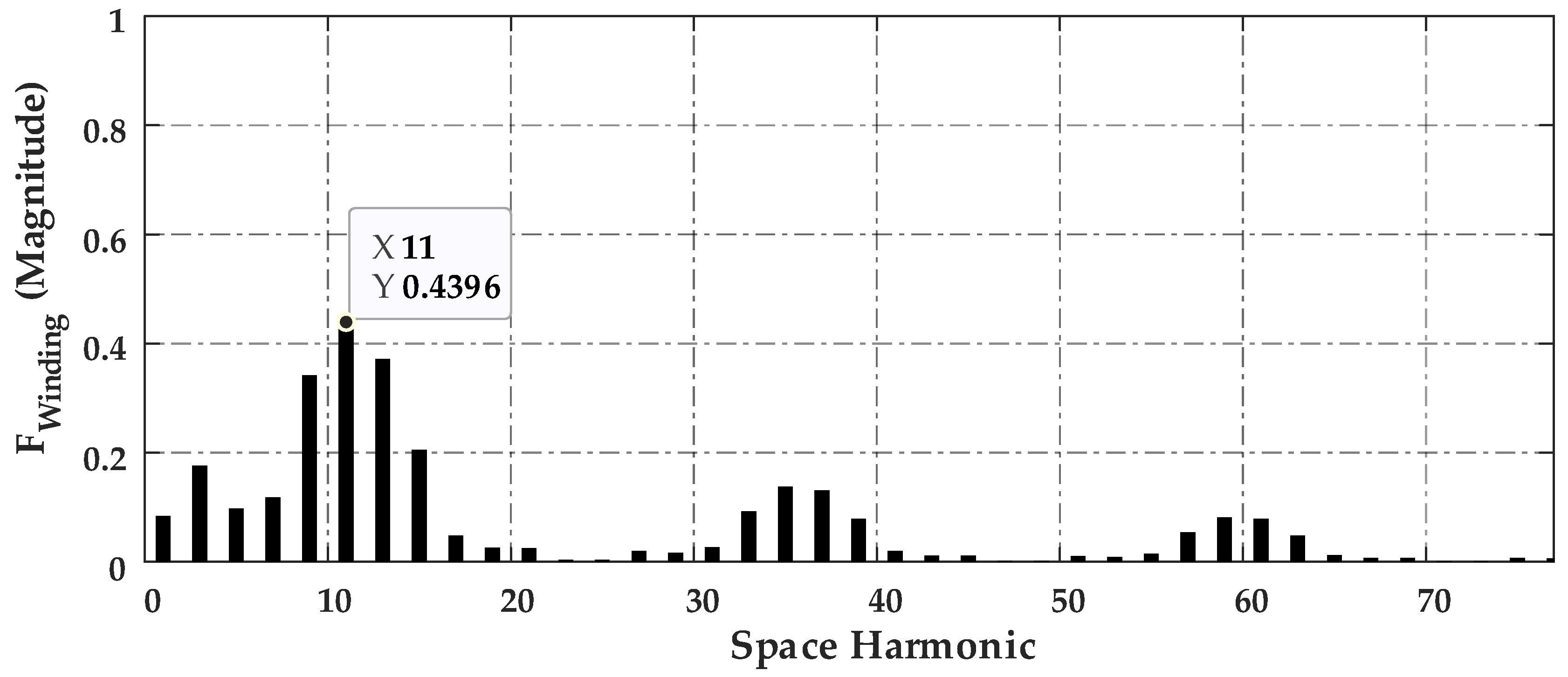
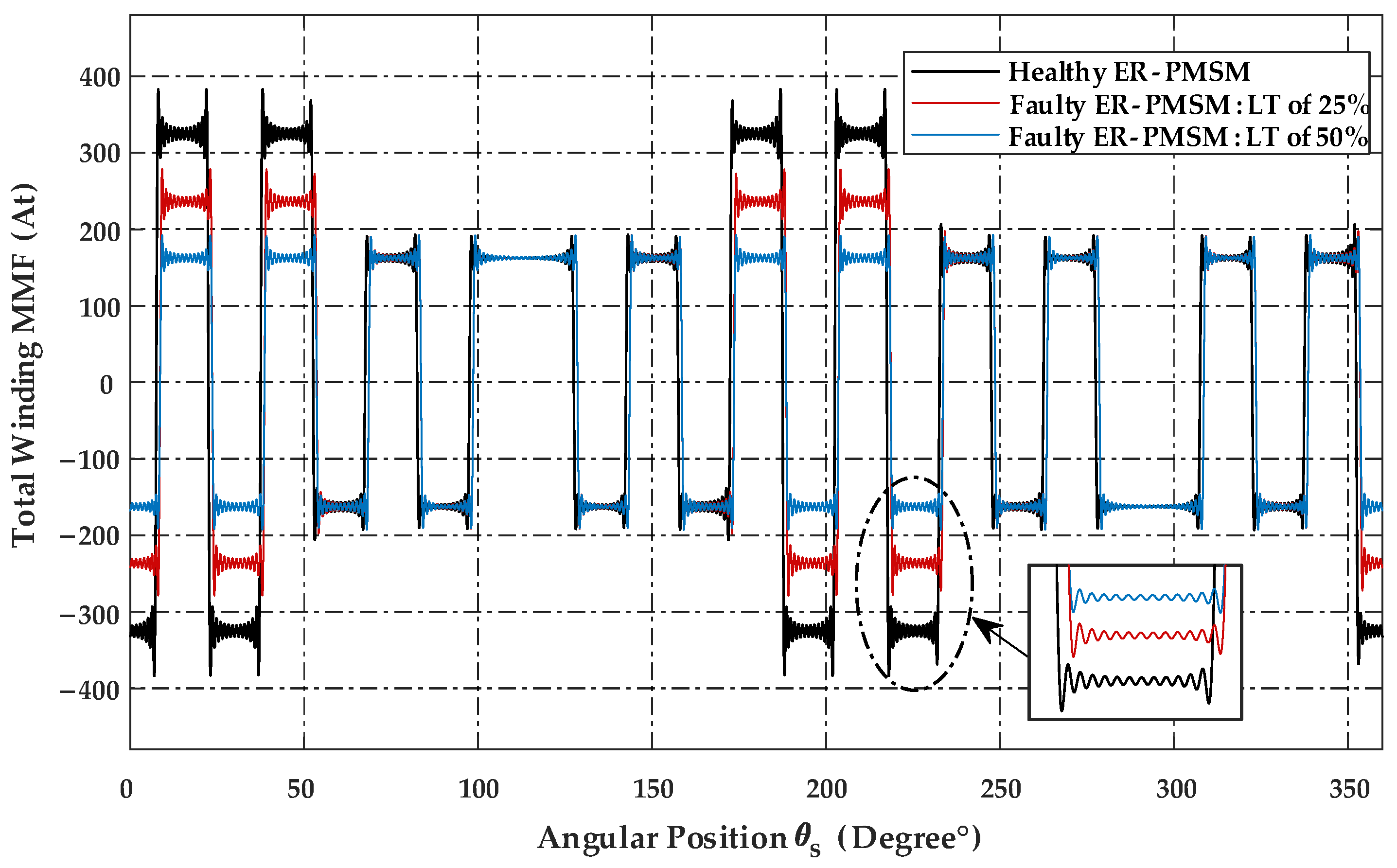
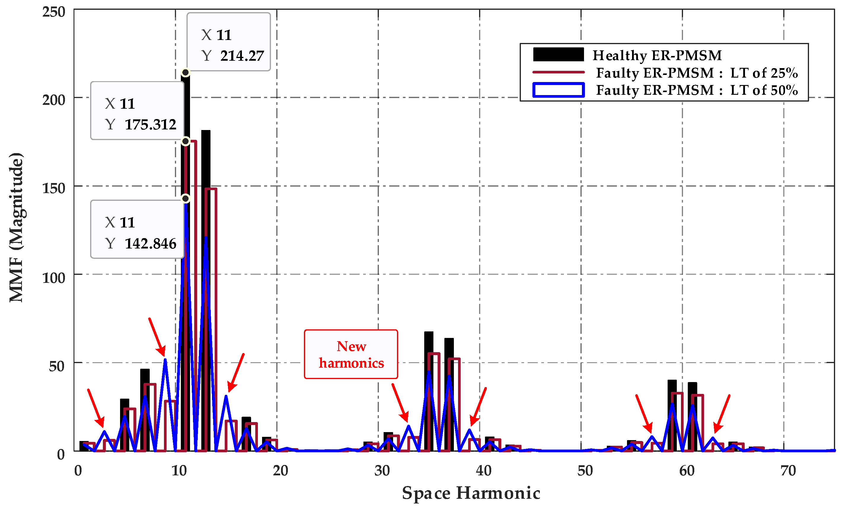
2.1.4. Magnetomotive Force (MMF)
- A.
- Healthy MMF of the ER-PMSM
- B.
- Faulty MMF of the ER-PMSM
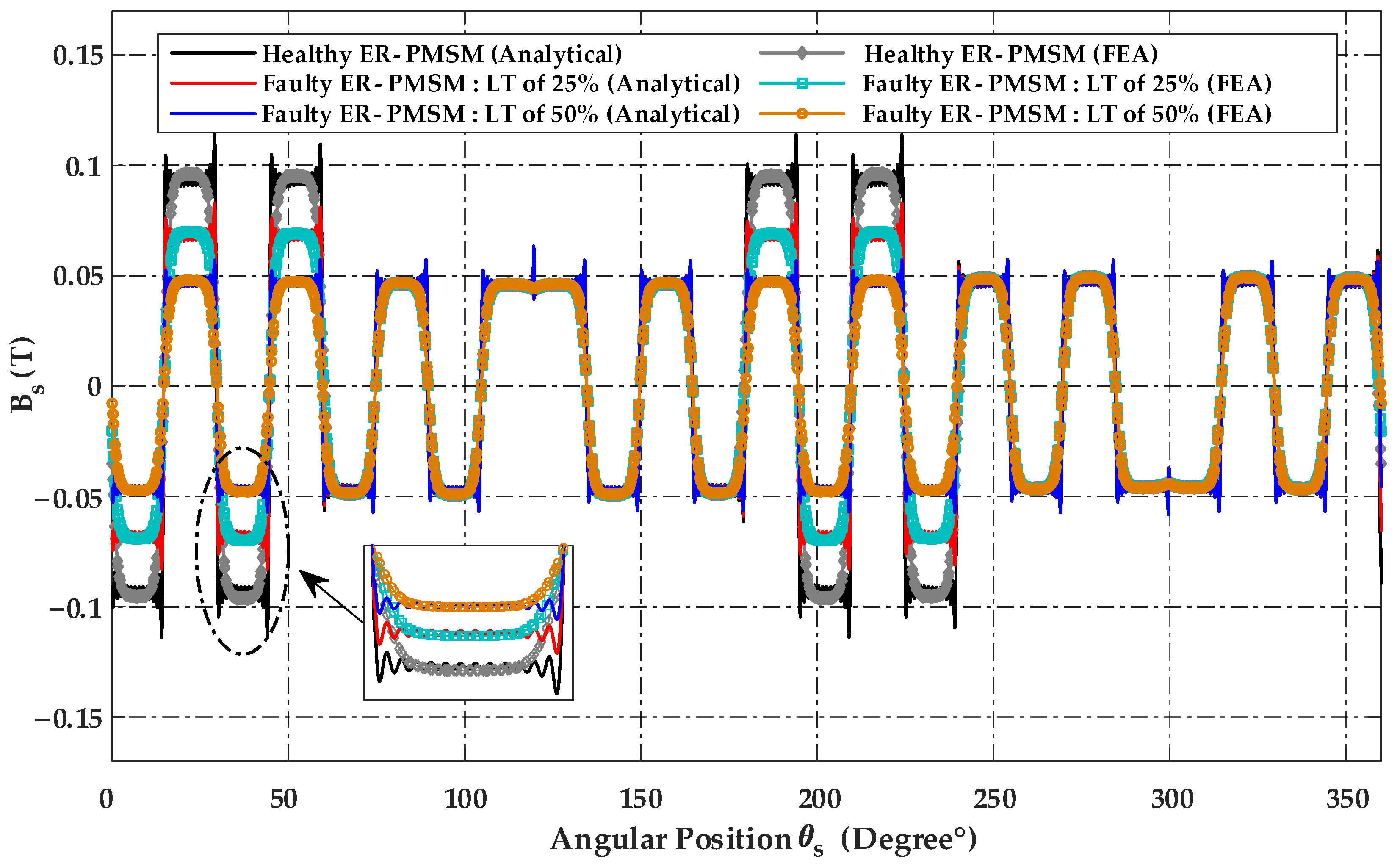
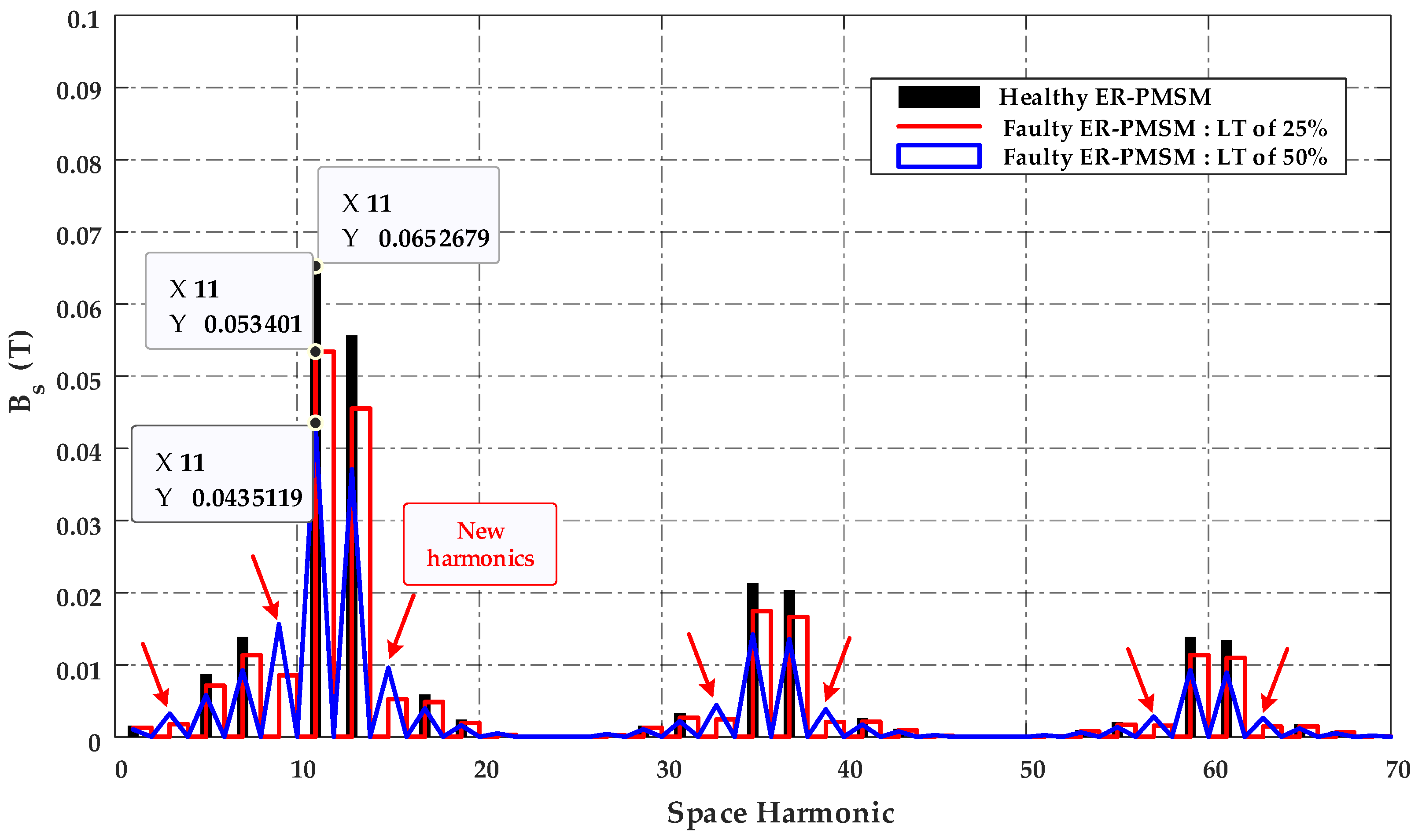
2.1.5. Air-Gap Flux Density
2.1.6. Inductances in Healthy and Faulty FSCW ER-PMSMs
- A.
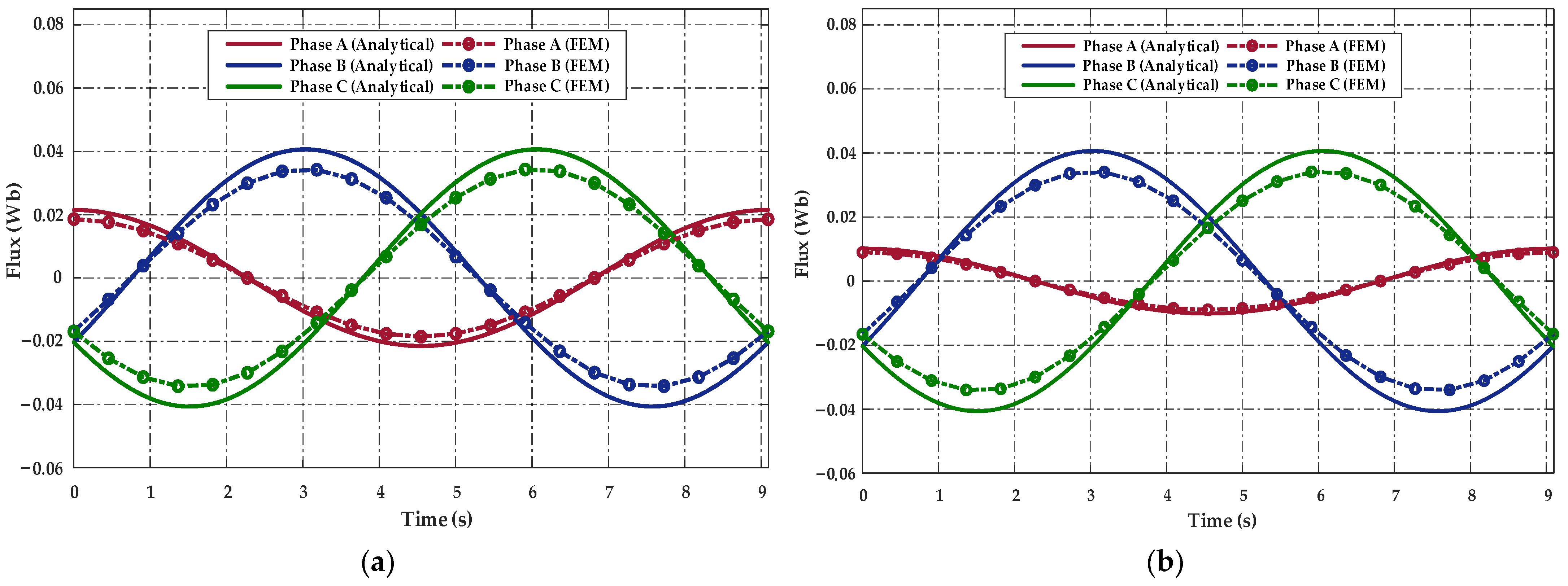
- Healthy Magnetic Flux
- B.
- Faulty Magnetic Flux
- C.
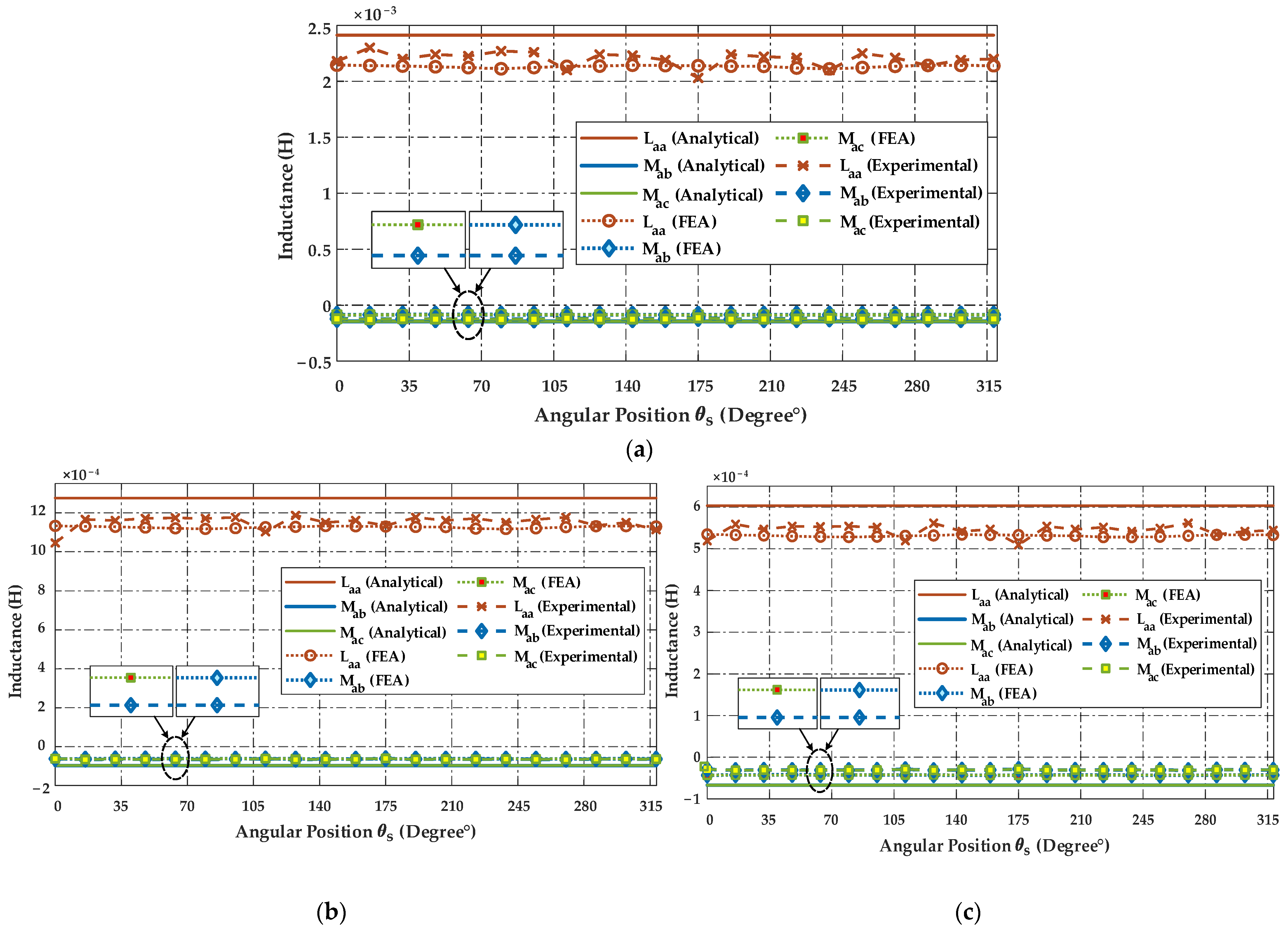
- Inductances in Healthy and Faulty States
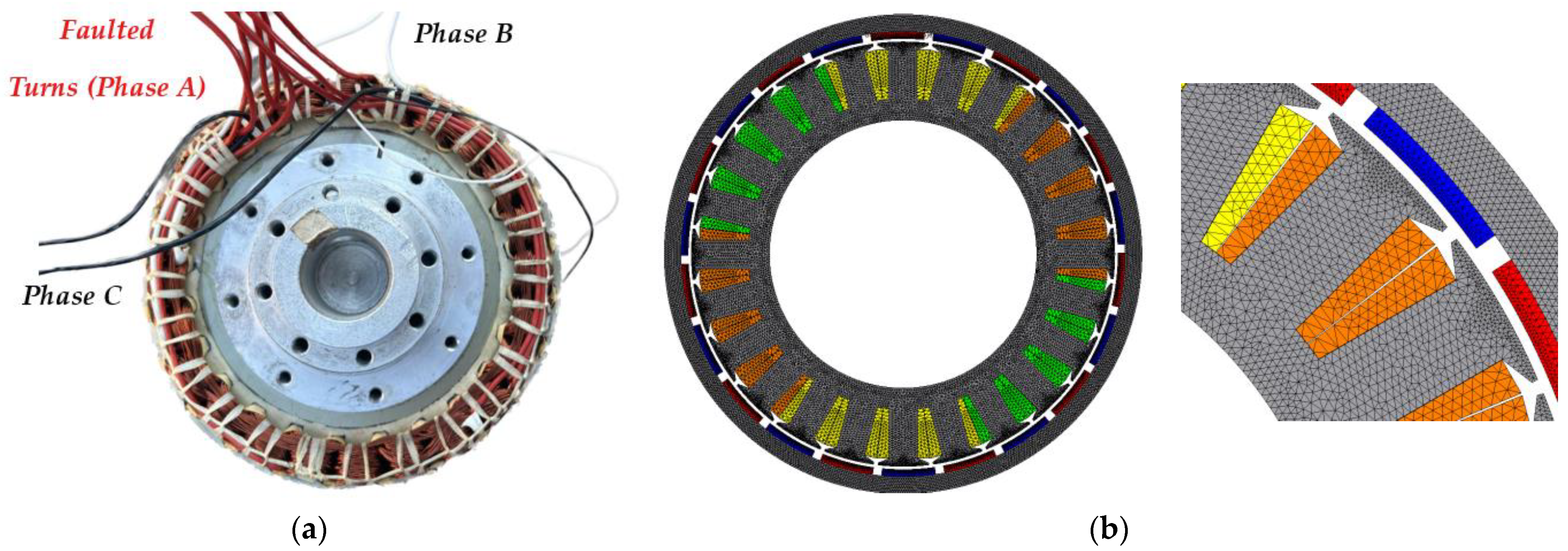
2.2. Numerical Validation: Finite Element Analysis
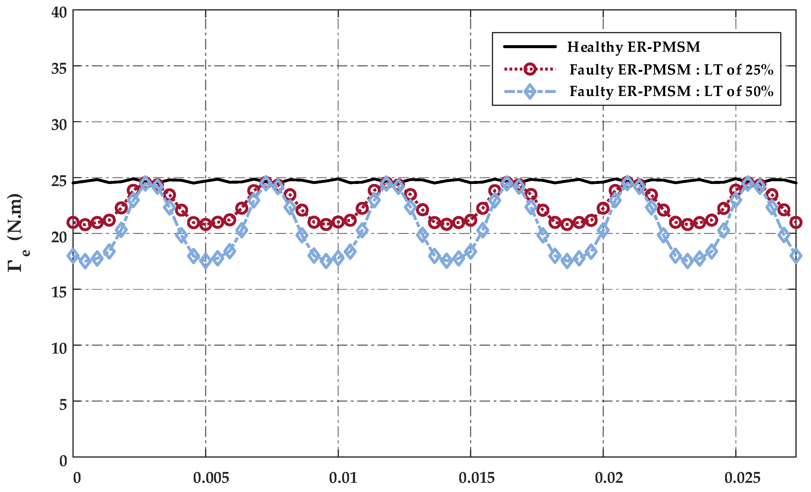
Performance Analysis of ER-PMSM with LTs Fault
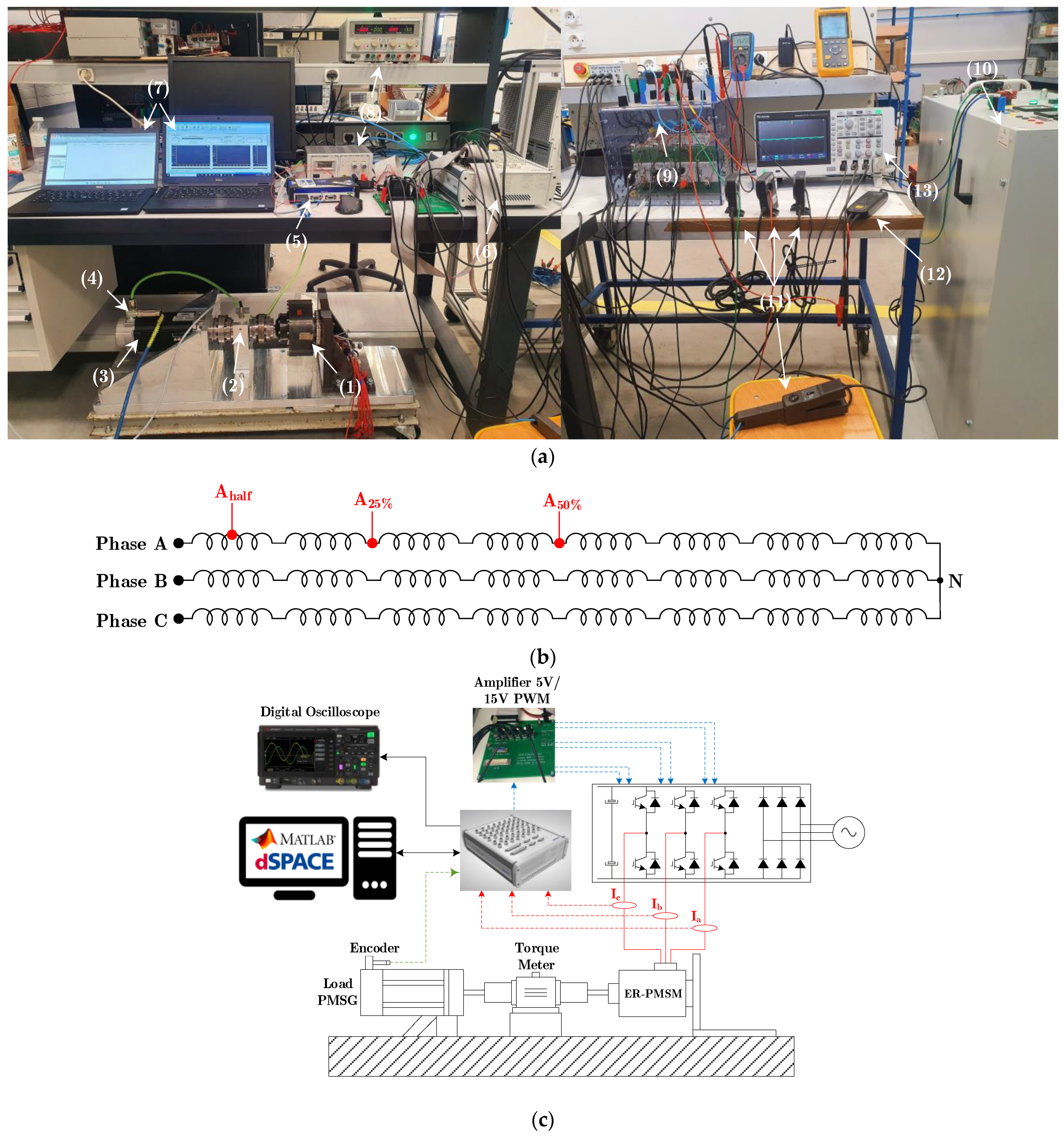
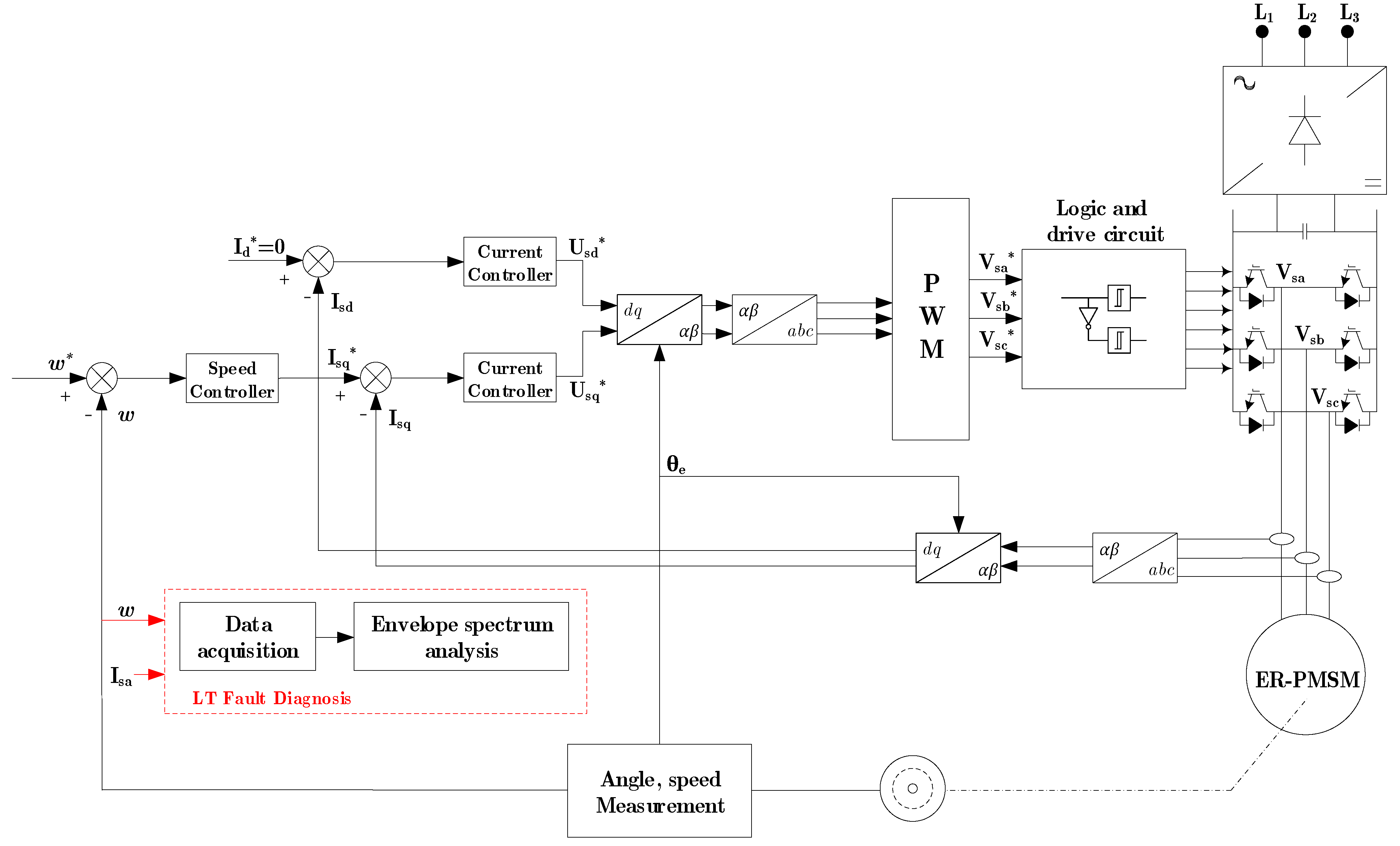
3. Experimental Setup
4. Experimental Results
4.1. Healthy State of the ER-PMSM
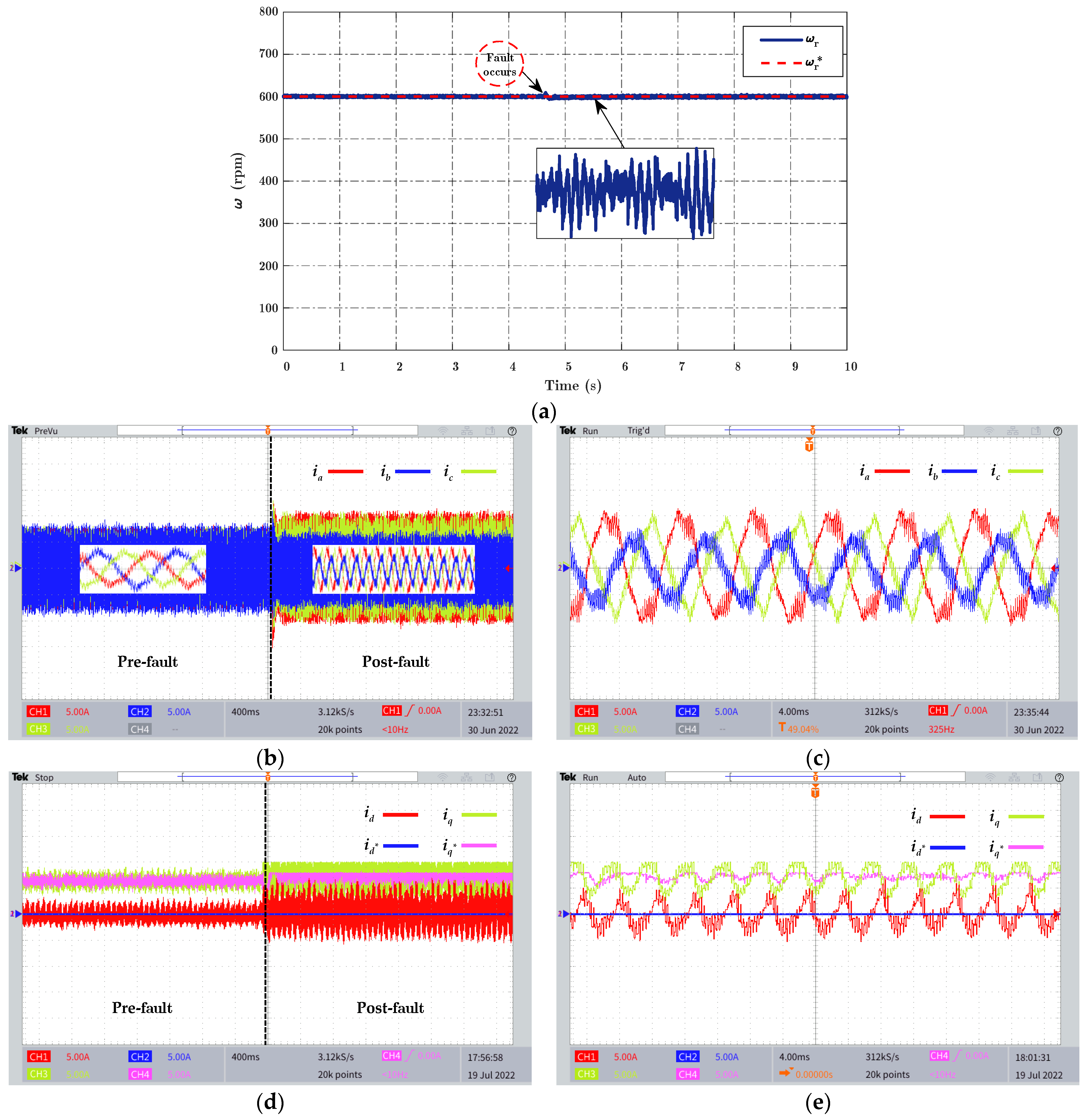
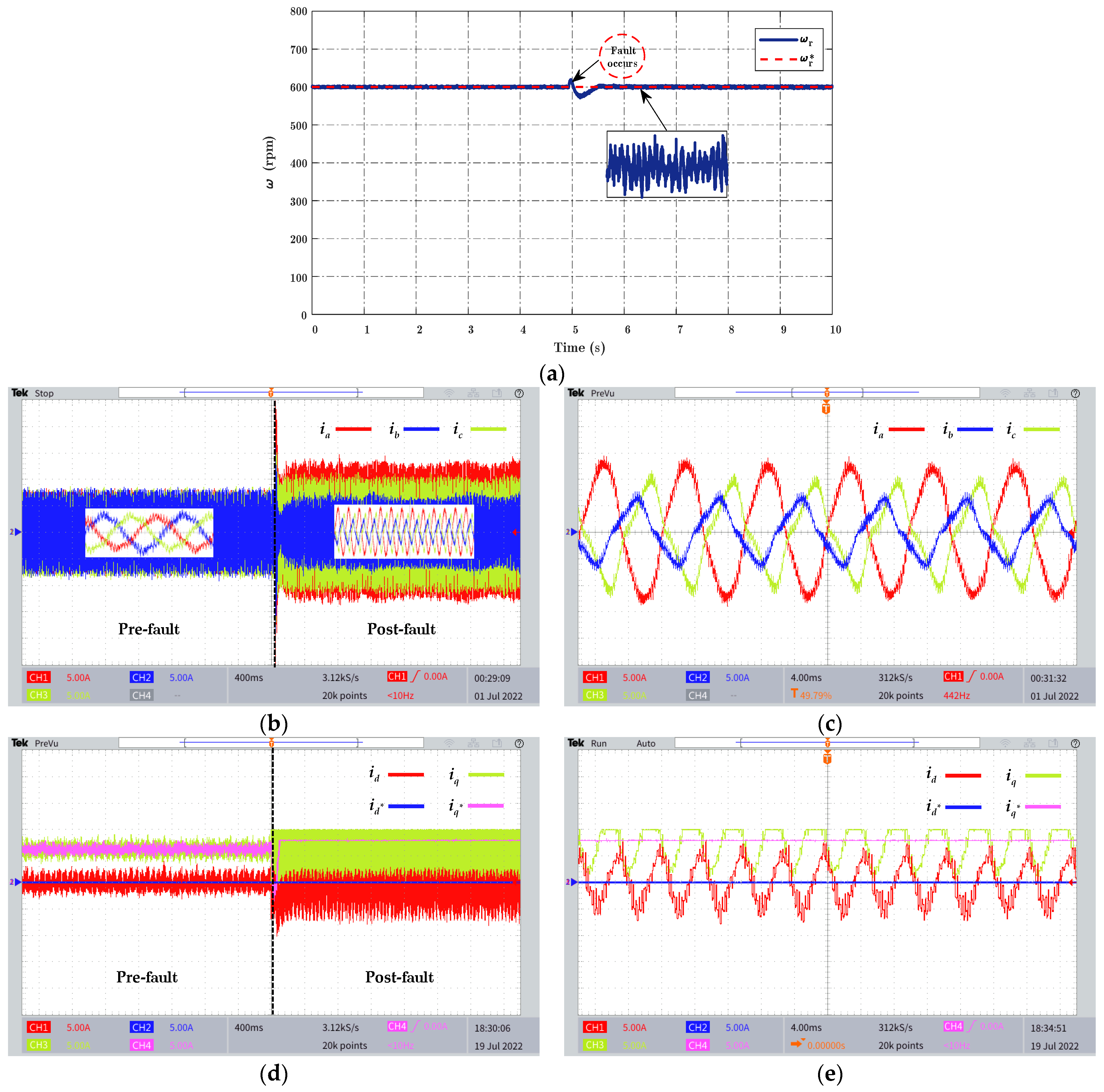
4.2. Faulty State of the ER-PMSM
- -
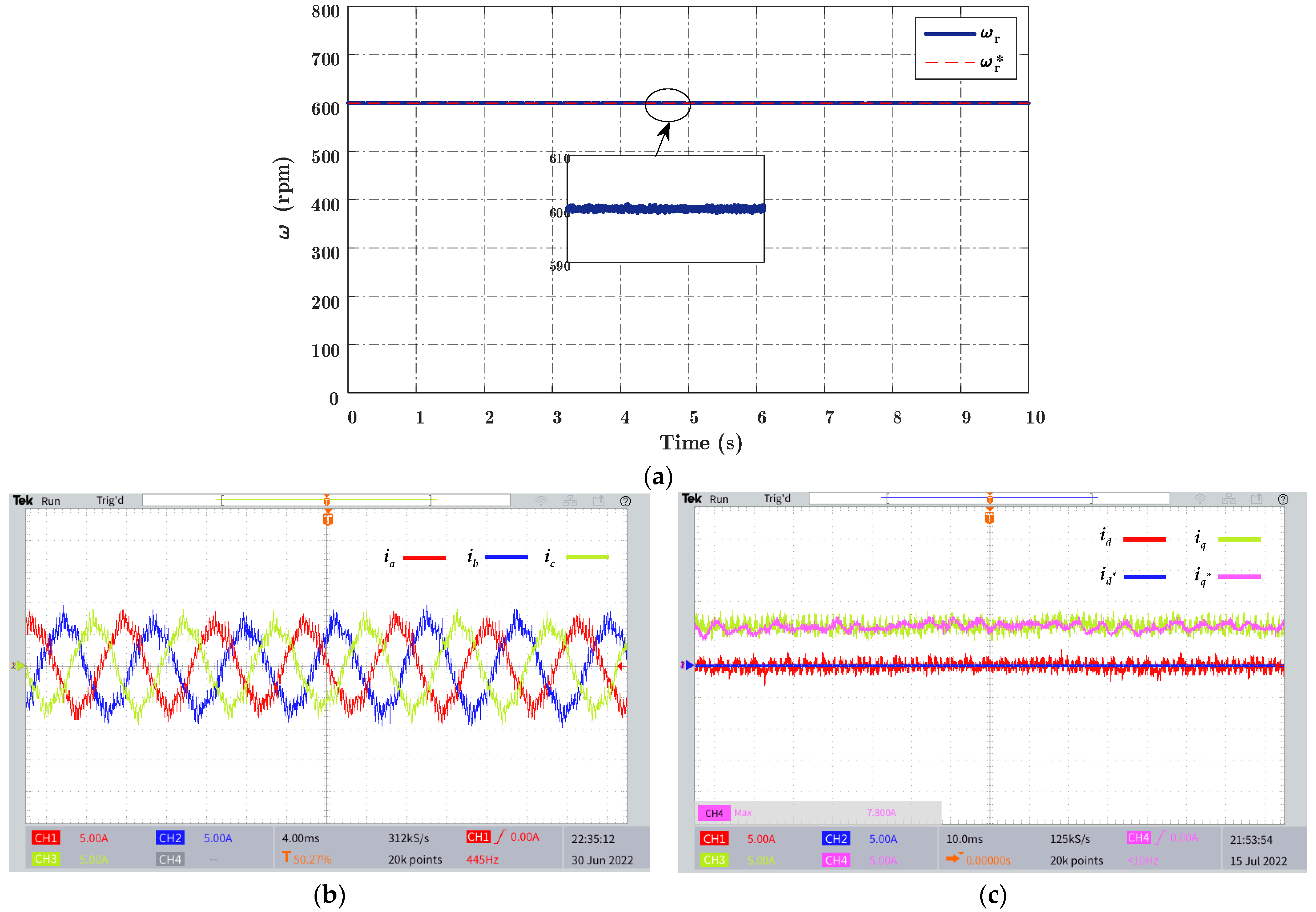
- The rotor speed is not substantially influenced by the LTs fault because of the control loop that hides and compensates for the effect of the fault;
- -
- High ripples arise in the stator current of phase A, the direct current id, and the quadratic current iq. The influence of the fault generates an unbalance and a noticeable variation in the current envelope.
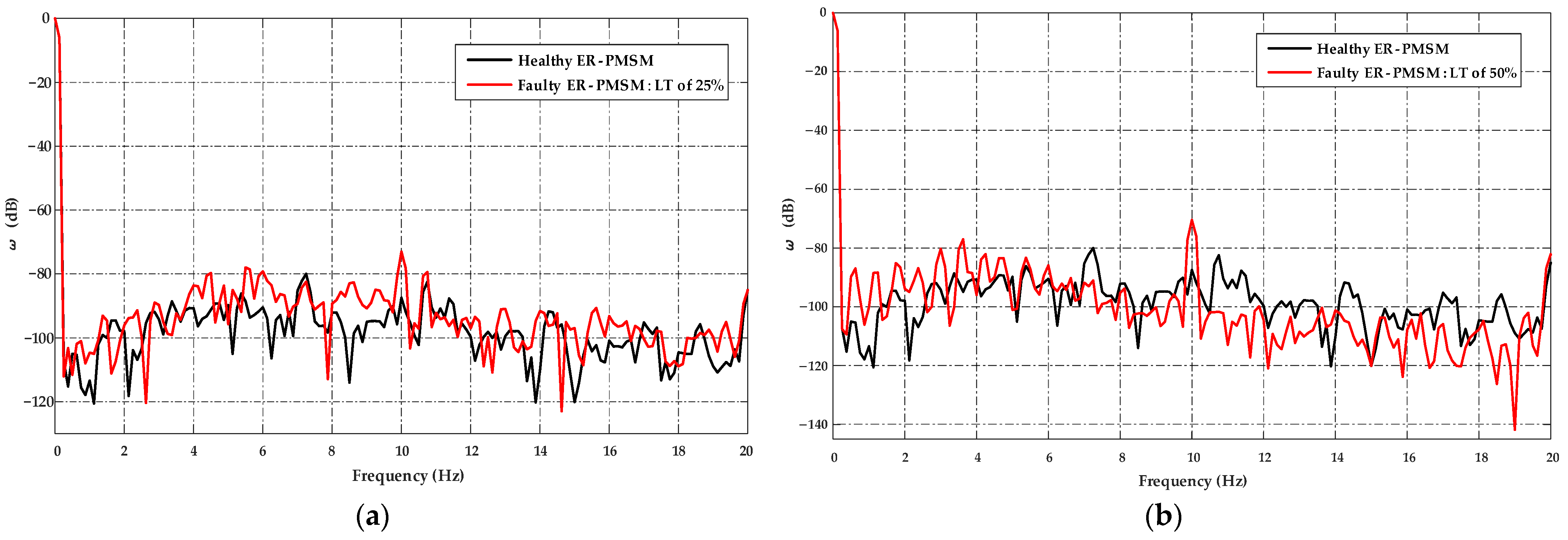
4.2.1. Motor Speed Signature Analysis
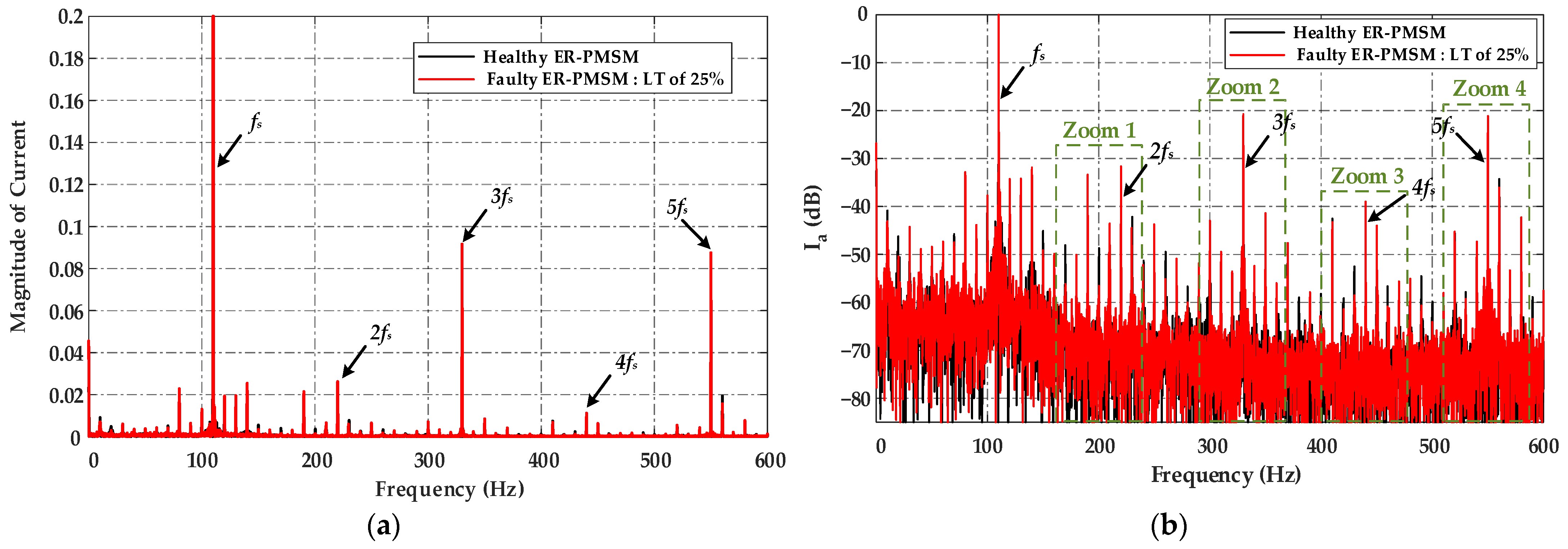
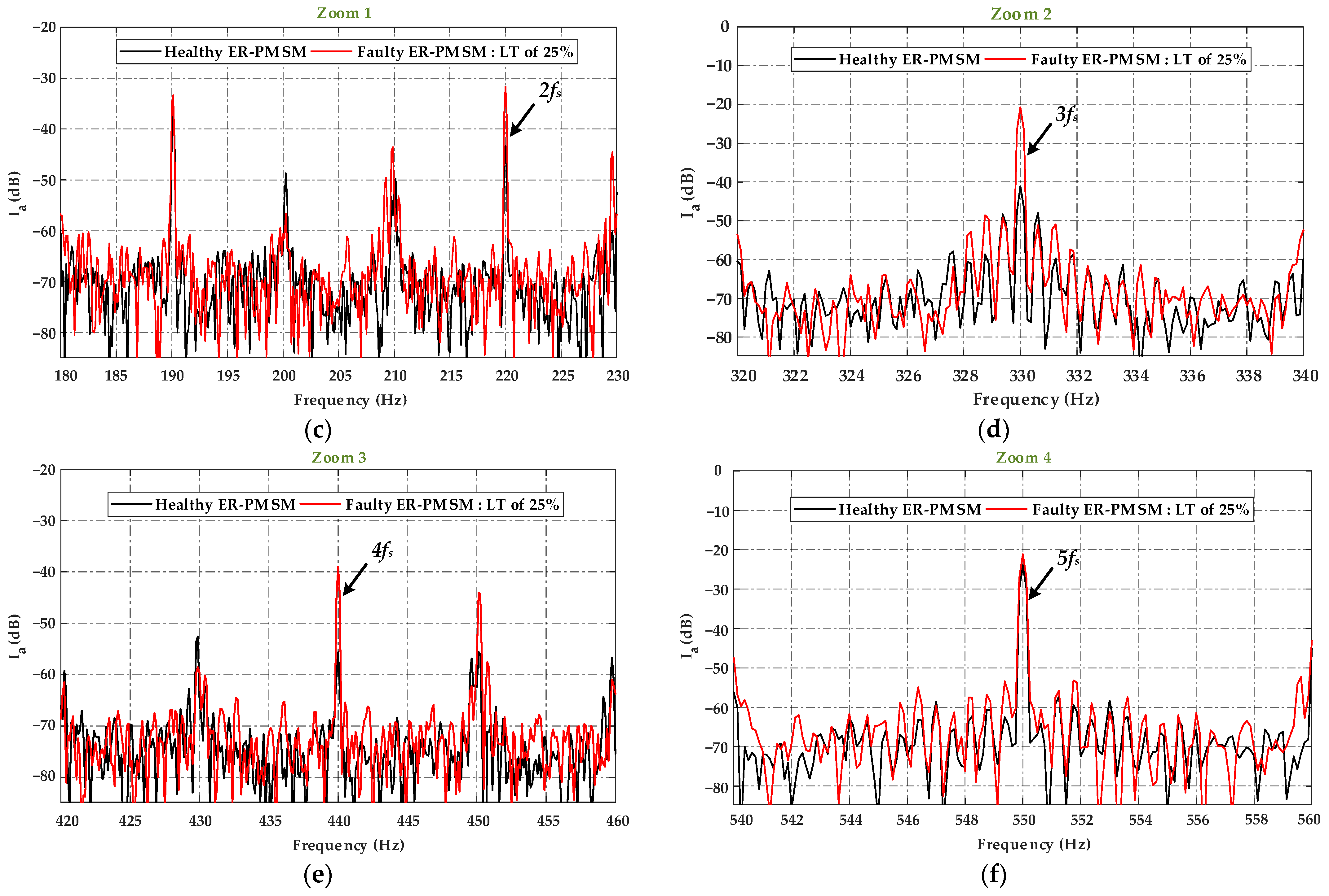
4.2.2. Motor Current Signature Analysis
5. Conclusions
Author Contributions
Funding
Data Availability Statement
Conflicts of Interest
References
- Łebkowski, A. Design, Analysis of the Location and Materials of Neodymium Magnets on the Torque and Power of in-Wheel External Rotor PMSM for Electric Vehicles. Energies 2018, 11, 2293. [Google Scholar] [CrossRef]
- Pop, C.V.; Fodorean, D.; Husar, C.; Irimia, C. Structural Behavior Evaluation of an In-Wheel Motor Based on Numerical and Experimental Approach. Electr. Eng. 2020, 102, 65–74. [Google Scholar] [CrossRef]
- Ma, C.; Gao, Y.; Degano, M.; Wang, Y.; Fang, J.; Gerada, C.; Zhou, S.; Mu, Y. Eccentric Position Diagnosis of Static Eccentricity Fault of External Rotor Permanent Magnet Synchronous Motor as an In-wheel Motor. IET Electr. Power Appl. 2020, 14, 2263–2272. [Google Scholar] [CrossRef]
- Ebrahimi, S.H.; Choux, M.; Huynh, V.K. Real-Time Detection of Incipient Inter-Turn Short Circuit and Sensor Faults in Permanent Magnet Synchronous Motor Drives Based on Generalized Likelihood Ratio Test and Structural Analysis. Sensors 2022, 22, 3407. [Google Scholar] [CrossRef] [PubMed]
- Ebrahimi, B.M.; Javan Roshtkhari, M.; Faiz, J.; Khatami, S.V. Advanced Eccentricity Fault Recognition in Permanent Magnet Synchronous Motors Using Stator Current Signature Analysis. IEEE Trans. Ind. Electron. 2014, 61, 2041–2052. [Google Scholar] [CrossRef]
- Belkhadir, A.; Belkhayat, D.; Zidani, Y.; Pusca, R.; Romary, R. Torque Ripple Minimization Control of Permanent Magnet Synchronous Motor Using Adaptive Ant Colony Optimization. In Proceedings of the 2022 8th International Conference on Control, Decision and Information Technologies (CoDIT), Istanbul, Turkey, 17–20 May 2022; pp. 629–635. [Google Scholar]
- Orlowska-Kowalska, T.; Wolkiewicz, M.; Pietrzak, P.; Skowron, M.; Ewert, P.; Tarchala, G.; Krzysztofiak, M.; Kowalski, C.T. Fault Diagnosis and Fault-Tolerant Control of PMSM Drives–State of the Art and Future Challenges. IEEE Access 2022, 10, 59979–60024. [Google Scholar] [CrossRef]
- Kudelina, K.; Asad, B.; Vaimann, T.; Rassõlkin, A.; Kallaste, A.; Khang, H. Van Methods of Condition Monitoring and Fault Detection for Electrical Machines. Energies 2021, 14, 7459. [Google Scholar] [CrossRef]
- Ullah, Z.; Hur, J. A Comprehensive Review of Winding Short Circuit Fault and Irreversible Demagnetization Fault Detection in PM Type Machines. Energies 2018, 11, 3309. [Google Scholar] [CrossRef]
- Chen, Y.; Liang, S.; Li, W.; Liang, H.; Wang, C. Faults and Diagnosis Methods of Permanent Magnet Synchronous Motors: A Review. Appl. Sci. 2019, 9, 2116. [Google Scholar] [CrossRef]
- Solís, R.; Torres, L.; Pérez, P. Review of Methods for Diagnosing Faults in the Stators of BLDC Motors. Processes 2022, 11, 82. [Google Scholar] [CrossRef]
- Liang, H.; Chen, Y.; Liang, S.; Wang, C. Fault Detection of Stator Inter-Turn Short-Circuit in PMSM on Stator Current and Vibration Signal. Appl. Sci. 2018, 8, 1677. [Google Scholar] [CrossRef]
- Hang, J.; Zhang, J.; Cheng, M.; Huang, J. Online Interturn Fault Diagnosis of Permanent Magnet Synchronous Machine Using Zero-Sequence Components. IEEE Trans. Power Electron. 2015, 30, 6731–6741. [Google Scholar] [CrossRef]
- Yepes, A.G.; Fonseca, D.S.B.; Antunes, H.R.P.; Lopez, O.; Marques Cardoso, A.J.; Doval-Gandoy, J. Discrimination Between Eccentricity and Interturn Faults Using Current or Voltage-Reference Signature Analysis in Symmetrical Six-Phase Induction Machines. IEEE Trans. Power Electron. 2023, 38, 2421–2434. [Google Scholar] [CrossRef]
- Yang, M.; Chai, N.; Liu, Z.; Ren, B.; Xu, D. Motor Speed Signature Analysis for Local Bearing Fault Detection with Noise Cancellation Based on Improved Drive Algorithm. IEEE Trans. Ind. Electron. 2020, 67, 4172–4182. [Google Scholar] [CrossRef]
- Haje Obeid, N.; Battiston, A.; Boileau, T.; Nahid-Mobarakeh, B. Early Intermittent Interturn Fault Detection and Localization for a Permanent Magnet Synchronous Motor of Electrical Vehicles Using Wavelet Transform. IEEE Trans. Transp. Electrif. 2017, 3, 694–702. [Google Scholar] [CrossRef]
- Espinosa, A.G.; Rosero, J.A.; Cusido, J.; Romeral, L.; Ortega, J.A. Fault Detection by Means of Hilbert–Huang Transform of the Stator Current in a PMSM With Demagnetization. IEEE Trans. Energy Convers. 2010, 25, 312–318. [Google Scholar] [CrossRef]
- Pusca, R.; Romary, R.; Touti, E.; Livinti, P.; Nuca, I.; Ceban, A. Procedure for Detection of Stator Inter-Turn Short Circuit in Ac Machines Measuring the External Magnetic Field. Energies 2021, 14, 1132. [Google Scholar] [CrossRef]
- Irhoumah, M.; Pusca, R.; Lefèvre, E.; Mercier, D.; Romary, R. Stray Flux Multi-Sensor for Stator Fault Detection in Synchronous Machines. Electronics 2021, 10, 2313. [Google Scholar] [CrossRef]
- Irhoumah, M.; Pusca, R.; Lefevre, E.; Mercier, D.; Romary, R.; Demian, C. Information Fusion with Belief Functions for Detection of Interturn Short-Circuit Faults in Electrical Machines Using External Flux Sensors. IEEE Trans. Ind. Electron. 2018, 65, 2642–2652. [Google Scholar] [CrossRef]
- Irhoumah, M.; Pusca, R.; Lefevre, E.; Mercier, D.; Romary, R. Detection of the Stator Winding Inter-Turn Faults in Asynchronous and Synchronous Machines Through the Correlation Between Harmonics of the Voltage of Two Magnetic Flux Sensors. IEEE Trans. Ind. Appl. 2019, 55, 2682–2689. [Google Scholar] [CrossRef]
- Shih, K.-J.; Hsieh, M.-F.; Chen, B.-J.; Huang, S.-F. Machine Learning for Inter-Turn Short-Circuit Fault Diagnosis in Permanent Magnet Synchronous Motors. IEEE Trans. Magn. 2022, 58, 1–7. [Google Scholar] [CrossRef]
- Pietrzak, P.; Wolkiewicz, M.; Orlowska-Kowalska, T. PMSM Stator Winding Fault Detection and Classification Based on Bispectrum Analysis and Convolutional Neural Network. IEEE Trans. Ind. Electron. 2023, 70, 5192–5202. [Google Scholar] [CrossRef]
- Farshadnia, M. Advanced Theory of Fractional-Slot Concentrated- Wound Permanent Magnet Synchronous Machines; Springer: Berlin/Heidelberg, Germany, 2018; ISBN 978-981-10-8708-0. [Google Scholar]
- Pyrhonen, J. Juha Pyrhönen, Tapani Jokinen, Valéria Hrabovcová. In Design of Rotating Electrical Machines; Wiley: Hoboken, NJ, USA, 2014; Volume 614, ISBN 9781118581575. [Google Scholar]
- Bianchi, N.; Fornasiero, E. Impact of MMF Space Harmonic on Rotor Losses in Fractional-Slot Permanent-Magnet Machines. IEEE Trans. Energy Convers. 2009, 24, 323–328. [Google Scholar] [CrossRef]
- EL-Refaie, A.M. Fractional-Slot Concentrated-Windings Synchronous Permanent Magnet Machines: Opportunities and Challenges. IEEE Trans. Ind. Electron. 2010, 57, 107–121. [Google Scholar] [CrossRef]
- Di Tommaso, A.O.; Genduso, F.; Miceli, R. A Software for the Evaluation of Winding Factor Harmonic Distribution in High Efficiency Electrical Motors and Generators. In Proceedings of the 2013 8th Eighth International Conference and Exhibition on Ecological Vehicles and Renewable Energies (EVER), Monte Carlo, Monaco, 27–30 March 2013. [Google Scholar] [CrossRef]
- Hamiti, T.; Lubin, T.; Baghli, L.; Rezzoug, A. Modeling of a Synchronous Reluctance Machine Accounting for Space Harmonics in View of Torque Ripple Minimization. Math. Comput. Simul. 2010, 81, 354–366. [Google Scholar] [CrossRef]
- IEEE Std 115a; IEEE Standard Procedures for Obtaining Synchronous Machine Parameters by Standstill Frequency Response Testing. IEEE: Piscatway, NJ, USA, 1987.
- Shi, P.; Chen, Z.; Vagapov, Y.; Zouaoui, Z. A New Diagnosis of Broken Rotor Bar Fault Extent in Three Phase Squirrel Cage Induction Motor. Mech. Syst. Signal Process. 2014, 42, 388–403. [Google Scholar] [CrossRef]
- Moumene, I.; Ouelaa, N. Application of the Wavelets Multiresolution Analysis and the High-Frequency Resonance Technique for Gears and Bearings Faults Diagnosis. Int. J. Adv. Manuf. Technol. 2016, 83, 1315–1339. [Google Scholar] [CrossRef]


| Parameter | Symbol | Value | Parameter | Symbol | Value |
|---|---|---|---|---|---|
| Rated power (kW) | P | 1.5 | Inner rotor diameter (mm) | -- | 183 |
| Rated speed (rpm) | w | 600 | Length (mm) | Laxe | 35 |
| DC bus voltage (V) | VDC | 150 | Air-gap length (mm) | g | 1.365 |
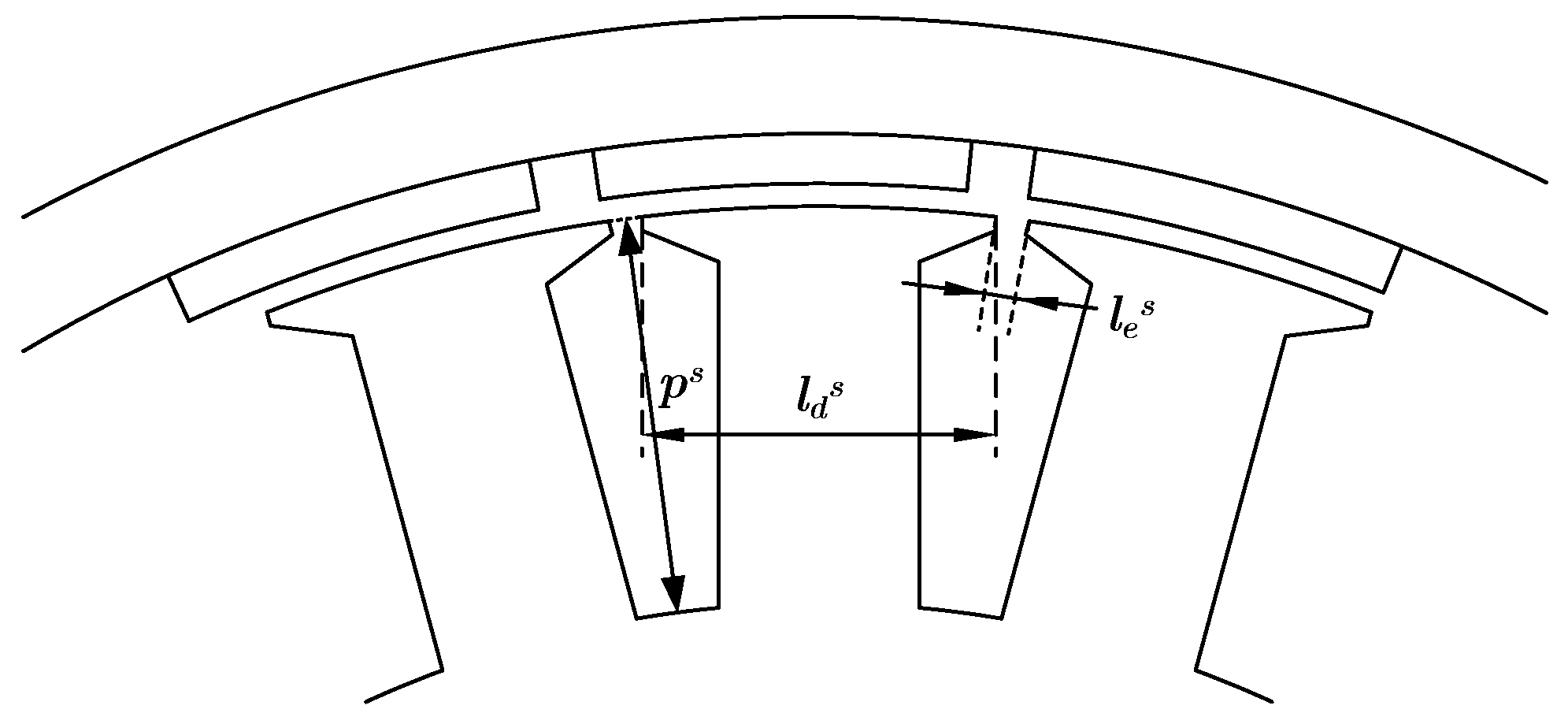
| Rated current (ARMS) | IN | 11 | Stator slot width (mm) | les | 10.37 |
| Rated torque (Nm) | Гe | 24 | Stator tooth width (mm) | lds | 21.1431 |
| Number of poles | p | 22 | Stator fictive slot depth (mm) | ps | 2.0740 |
| Number of phases | m | 3 | Slot opening width (mm) | 2 | |
| Number of slots | Ns | 24 | Magnet thickness (mm) | hm | 3 |
| Number of turns per coil | NT | 22 | Residual flux density of PM (T) | Br | 1.26 |
| Outer stator diameter (mm) | -- | 112 | Magnet-arc to pole-pitch ratio (%) | αp | 85.55 |
| Inner stator radius (mm) | Rs | 88.6350 | Permanent magnets | -- | NdFeB N38SH |
| Outer rotor diameter (mm) | -- | 186 | Magnetic steel | -- | M530-50A |
| State | Torque Ripples (N·m) |
|---|---|
| Healthy ER-PMSM | |
| Faulty state: LTs of 25% | |
| Faulty state: LTs of 50% |
| ER-PMSM Magnitude (dB) | Current (dB) | ||||
|---|---|---|---|---|---|
| fs = 110 Hz | 2fs = 220 Hz | 3fs = 330 Hz | 4fs = 440 Hz | 5fs = 550 Hz | |
| Healthy state | 0 | −43.361 | −41.096 | −55.616 | −23.937 |
| Faulty state: LTs of Ahalf | 0 | −43.177 | −35.001 | −45.819 | −22.828 |
| Faulty state: LTs of 25% | 0 | −31.636 | −20.759 | −38.989 | −21.159 |
| Faulty state: LTs of 50% | 0 | −37.708 | −20.689 | −42.237 | −31.881 |
Disclaimer/Publisher’s Note: The statements, opinions and data contained in all publications are solely those of the individual author(s) and contributor(s) and not of MDPI and/or the editor(s). MDPI and/or the editor(s) disclaim responsibility for any injury to people or property resulting from any ideas, methods, instructions or products referred to in the content. |
© 2023 by the authors. Licensee MDPI, Basel, Switzerland. This article is an open access article distributed under the terms and conditions of the Creative Commons Attribution (CC BY) license (https://creativecommons.org/licenses/by/4.0/).
Share and Cite
Belkhadir, A.; Pusca, R.; Belkhayat, D.; Romary, R.; Zidani, Y. Analytical Modeling, Analysis and Diagnosis of External Rotor PMSM with Stator Winding Unbalance Fault. Energies 2023, 16, 3198. https://doi.org/10.3390/en16073198
Belkhadir A, Pusca R, Belkhayat D, Romary R, Zidani Y. Analytical Modeling, Analysis and Diagnosis of External Rotor PMSM with Stator Winding Unbalance Fault. Energies. 2023; 16(7):3198. https://doi.org/10.3390/en16073198
Chicago/Turabian StyleBelkhadir, Ahmed, Remus Pusca, Driss Belkhayat, Raphaël Romary, and Youssef Zidani. 2023. "Analytical Modeling, Analysis and Diagnosis of External Rotor PMSM with Stator Winding Unbalance Fault" Energies 16, no. 7: 3198. https://doi.org/10.3390/en16073198
APA StyleBelkhadir, A., Pusca, R., Belkhayat, D., Romary, R., & Zidani, Y. (2023). Analytical Modeling, Analysis and Diagnosis of External Rotor PMSM with Stator Winding Unbalance Fault. Energies, 16(7), 3198. https://doi.org/10.3390/en16073198