Article

Analytical Modeling of Magnetic Field Distribution at No Load for Surface Mounted Permanent Magnet Machines

by
Antonino Di Gerlando
and
Claudio Ricca
*
Department of Energy, Politecnico di Milano, via La Masa 34, 20156 Milan, Italy
*
Author to whom correspondence should be addressed.
Energies 2023, 16(7), 3197; https://doi.org/10.3390/en16073197
Submission received: 28 February 2023 / Revised: 16 March 2023 / Accepted: 28 March 2023 / Published: 1 April 2023

Abstract

:
This paper presents an analytical study of the air-gap magnetic field of a Surface Permanent Magnet (SPM) linear machine under no load. By means of the method of images, the complex expression of the magnetic field of a conductor, inside the air gap between two smooth iron surfaces, is retrieved. Then, integrating the conductor expression, the formulation of the magnetic field of a current sheet and thus the one of a SPM, using two vertical current sheets, is obtained. At last, the no-load magnetic field expression, for a generic time instant, of a slotless machine is retrieved. The novelty of the proposed approach is the availability, due to a different calculation approach, of a unique closed-form formulation for the slotless machine air-gap field, a quantity that, in literature, is usually present in Fourier series formulation. Additionally, as a means to calculate integral quantities and show the goodness of the method a complex slotting function is introduced to account for the slotted geometry. Finally, starting from Lorenz’s force formulation, the expression of the Maxwell tensor in complex form is retrieved and the contribution of forces, integral of the complex stress tensor quantity, will be calculated and compared with FEM simulations, showing a good agreement also with the analytical slotted model.

1. Introduction

The study of analytical techniques to predict the magnetic field distribution inside the air gap of the electrical machines has been, and still is a topic of interest, also after the improvement experienced by numerical methods. It is so because analytical methods not only help us to better understand the core parameters which influence the physical phenomena; but also because they are generally faster than their counterpart. Thus, even if under simplifying hypotheses, they are helpful, especially during the early part of a design project to predict motor performances or to carry out optimizations. Through the study of the air-gap magnetic field, it is possible to calculate quantities like flux linkages, back electromotive forces, and magnetic forces, hence, investigating the cause of noise and vibration inside electrical machines.
Among the analytical methods concerning the flux density distributions inside the air-gap of the electrical machines present in literature, it is found the method based on the solution of the analytical 2D Laplacian quasi-Poissonian field equations assuming infinitely permeable iron [1,2]. Those types of models were introduced for slotless SPM motors in [3] and later extended to slotted geometries, throughout the use of the relative air-gap permeance [4], for the normal flux density component only, which, expressed in term of Fourier series and multiplied to the slotless flux density distribution gives the flux density profile of the slotted machine. Nevertheless, the lack of tangential flux density component of the slotted geometry, developed in [4] does not allow to retrieve quantities like the cogging torque, by integrating the tangential component of the Maxwell stress tensor. To this purpose, [5] introduced the complex permeance function allowing us to also retrieve the tangential component of the flux density air-gap field distribution and analytically calculate the torque, using the Maxwell stress tensor [6]; this process, unfortunately, requires the solution of a nonlinear complex equation, leading to higher computational time. The methods just mentioned together with the work done by Carter [7] and the Schwarz–Christoffel mapping method [8,9,10] fall all into the conformal mapping category.
Another category of models concerns the subdomain models, which solve the flux density field inside the slotted machine, by dividing the entire domain into subdomains, enclosing air, magnets, slots, and slot openings; solving Maxwell’s equations into it using the separation of variables [11,12,13]. Subdomains models can accurately predict flux density into magnetic air gap, magnets, and slot opening with very good accuracy, and they appear to be better also for the cogging torque calculation compared with permeance models [14].
Methods that rely on the equivalent magnetic circuit methods (EMC) can be also found and consist in drawing a magnetic circuit model of the machine with lumped or distributed reluctances parameters to model the machine’s magnetic flux tubes and retrieve quantities like flux linkages and average flux density values [15,16]. A variety of hybrids methods of the previously mentioned ones are also present [17,18,19].
Lastly, a less used and known category of analytical methods based on Lord’s Kelvin method of images as [20,21] can be found and the presented paper belongs to it. The method here introduced models the slotless field of an SPM machine, not solving the 2D Laplacian quasi-Poissonian field equations like Zhu did in [3], but using a different approach based on the method of images and duality between the electric and magnetic fields.
In Section 2.1 and Section 2.2 the flux density air-gap expression produced by the powered conductor stated by [22] and then formulated in complex form [23], has been extended to an indefinitely long current sheet energized by a linear current density: then, two vertical parallel current sheets have been used, in order to model a surface permanent magnet.
In Section 2.3 the totality of permanent magnets present on the machine periphery has been modeled introducing also the time variable.
Then, in Section 3.1, to account for the slotting effect, similarly to [5], a more compact formula of the relative air-gap permeance function has been introduced, starting from [24].
In Section 3.2, the flux density profile of the slotted machine, product of the complex slotting function, and the slotless flux density vector is retrieved and compared with FEM simulations, showing an outstanding agreement.
In Section 4.1, starting from the Lorentz’s force formula, the Maxwell stress tensor in complex form has been obtained and in Section 4.2 it is used to retrieve both the normal and tangential component of the total force of the slotted machine.
Finally in Section 4.3 the computational time required for the proposed method is shown in comparison with FEM simulations.
What distinguishes the proposed model from the other ones is that: the slotless formulation is not expressed by means of a solution in the Fourier series but by means of a closed-form analytical formulation. Furthermore, the high level of accuracy of the flux density normal and tangential air-gap components calculation is in the same range as the sub-domain models.
Among the advantages of the above-mentioned method, there is the simplicity of implementation and fast response, bringing accurate results also for the Maxwell stress tensor calculation, which is not an easy task as it is well known in the literature. On the other side, the method shows the weak points of assuming unity relative recoil permeability and neglect saturation. However, modern SPM machines are usually equipped with PM materials with pu recoil permeability typically around 1.09 [25,26,27], so quite close to vacuum permeability. Moreover, it is possible to show that the actual air-gap flux density distribution taking into account saturation can be obtained from the unsaturated one, multiplied by suitably calculated saturation correcting factors.

2. Magnetic Field between Smooth Ferromagnetic Surfaces

2.1. Linear Conductor with Infinitesimal Section

The magnetic field distribution produced by an indefinite current-carrying conductor, cutting the paper plane perpendicularly and placed into the air gap between two smooth ideal ferromagnetic surfaces, can be modeled analytically in Cartesian coordinates, using the method of images described in [22]. The aforementioned method makes use of the following assumptions and limitations:
i
Stator and moving surfaces are supposed to be smooth and separated by an air gap of uniform width.
ii
Magnetic field is just 2D and lies in the paper plane.
iii
The machine is supposed to be so long into the paper plane direction, so end effects are negligible.
iv
Relative recoil permeability is considered to be equal to the vacuum permeability ( μ r = 1 ).
v
Iron permeability is assumed to be infinite so the method of superimposition can be used.
vi
The iron parts are perfectly laminated thus no eddy current can be induced in the iron by the varying magnetic field.
vii
The conductors placed inside the air gap extend indefinitely perpendicular to the paper plane.
viii
Skin effect due to alternating currents flowing in the conductors is neglected.
By representing the magnetic field vector quantities as complex numbers, made by a real and imaginary part, representative respectively of the tangential and normal vector components, let’s focus on Figure 1, where a conductor powered by a current I, flowing perpendicularly outwards the paper plane x y , is positioned into the air-gap complex plane at a generic point p of coordinates z p = x p + j y p , between two smooth infinitely permeable iron surfaces.
To be able to calculate the field strength vector at a certain point z between two smooth iron surfaces, the aforementioned configuration can be exchanged with an equivalent one in which the iron parts are removed and substituted with two infinite series of images. The conductors from the first and second series of images are placed at positions z p + j 2 n g and z ¯ p + j 2 n g , with n Z ranging from minus and plus infinity. By using the theorem of superimposition the field strength inside the air-gap can be expressed as the sum of two mathematical series representative of the two image series, a formulation a little complicated which has been simplified in [23] giving rise to the formulation:
B c ( z ) = μ o j I 4 g · coth π ( z ¯ z ¯ p ) 2 g + coth π ( z ¯ z p ) 2 g
where I is the current flowing inside the conductor, g the air-gap length, z p and z ¯ p the position of the conductor in complex coordinates and its conjugate.

2.2. Permanent Magnet Current Sheet Model

As it is well known already in the literature, the magnetic field produced by a permanent magnet can be modeled by the use of current sheets. In the following subsection, the approach which models the magnetic field produced by a conductor set between two smooth ideal iron surfaces previously introduced will be extended to current sheets in order to model the magnetic field produced by surface permanent magnets.
In Figure 2 current sheet indefinitely extended into the paper plane and vertically oriented, inside the air gap of two smooth iron surfaces are considered, distributed along the points p, with coordinates z p = x p + j y p . This distribution has extreme points z p 1 = x p + j y p 1 and z p 2 = x p + j y p 2 .
Let’s assume that the current sheet is powered by a constant current density of Δ = I / h c s , flowing outwards the paper plane, where I is the total current and h c s the current sheet finite length. By taking into consideration an infinitesimal current sheet element Δ · d y p , it is possible to express the infinitesimal flux density air-gap complex vector as:
d B cs ( z ) = μ o j Δ d y p 4 g · coth π ( z ¯ x p + j y p ) 2 g + coth π ( z ¯ x p j y p ) 2 g .
Then, let’s integrate (2) between y p 1 and y p 2 , with y p 1 set to zero (the current sheet starts from the lower iron surface), the air-gap flux density vector, produced by a current sheet of length h c s , with z p 1 = x p + j 0 and z p 2 = x p + j y p 2 its ends points and powered by a current density Δ flowing outwards the paper plane is retrieved:
B cs ( z ) = μ o Δ 2 π · ln sinh π ( z ¯ x p + j y p 2 ) 2 g / sinh π ( z ¯ x p j y p 2 ) 2 g .
Making use of (3), the field of an SPM, leaning on the lower iron surface and with the north pole oriented positively towards y, can be modeled by the use of two current sheets vertically oriented, whose current density equals the PM coercivity H o = B r / μ o μ r . The first current sheet will be positioned on the right, inside the first quadrant, powered by a current density Δ = H o , flowing inwards the x y plane, whose ends are situated at z p 1 = b m / 2 + j 0 and z p 2 = b m / 2 + j h m , being b m and h m the width and height of the PM. The second one will instead be positioned symmetrically to the y axis on the left, inside the second quadrant, powered by a current density Δ = H o which flows outwards the plane and whose ends point equals the negative conjugates of points z p 1 and z p 2 , giving:
B PM ( z ) = B r 2 π μ r · { ln sinh π ( z ¯ z p 2 ) 2 g sinh π ( z ¯ z ¯ p 2 ) 2 g + ln sinh π ( z ¯ + z p 2 ) 2 g sinh π ( z ¯ + z ¯ p 2 ) 2 g } z p 2 = b m / 2 + j h m
wherein the real part B P M x ( z ) = Re { B PM ( z ) } and imaginary part B P M y ( z ) = Im { B PM ( z ) } represent the tangential and normal components of the vector flux density function of a generic complex point z, produced by an SPM leaning on the lower iron surface, with y as an axis of symmetry and north oriented positively towards it.
The theoretical case of a SPM, between two smooth iron surfaces, indefinitely extended along x, that lies on top of the lower iron surface, is now investigated making use of the FEM analysis and the analytical vertical current sheets model previously introduced. The magnet, positioned in the center of the coordinate system, has peripheral size b m = 102.05 mm and height h m = 10 mm, and its north points toward y positive. In Figure 3a,b the analytical and FEM normal and tangential flux density distribution components on the middle of the mechanical air gap at y M = g δ / 2 over the permanent magnet peripheral extension is plotted. FEM simulations have been carried out with infinitely permeable iron and relative recoil permeability set to one. Both the normal and tangential distributions are expressed in p.u. with respect to B i = μ o · U / g , which is the ideal flux density flat profile reference value, with U the air-gap magnetic voltage drop and g the distance between the ferromagnetic surfaces. is important to mention that, for the considered ideal case, where the magnet is between two smooth iron surfaces extended indefinitely along x, the magnetic voltage drop in the part of air-gap where the flux comes back, equals zero. Being the crossing area of the returning flux of infinite extension, as it is clearly shown in Figure 3a, everywhere the magnetic voltage drop is positive, thus B i = μ o H o h m / g . Figure 4a,b, instead show the normal and tangential analytical and FEM infinitely permeable iron flux density distributions generated by the permanent magnet between two smooth iron surfaces in the middle of the PM body.

2.3. Magnetic Field due to a Sequence of Permanent Magnets

The SPM current sheet model introduced in the previous subsection can be extended to a series of permanent magnets, to model the magnetic field produced by an SPM machine during no load working conditions. For the sake of simplicity, the method will be now applied to a linear SPM machine, but it can also be generalized for cylindrical geometries using conformal mapping, as it is done for a series of concentrated conductors in [23]. It is worth mentioning that the following method works also for more complex magnet shapes for example the Halbach ones. The machine type examined for the purpose is shown in Figure 5a whose main data are listed in Table 1; the machine sizes listed below are retrieved using a pre-design procedure applied to an axial flux PM machine, linearized along the average radius [28].
Let’s consider first the slotless machine pictured in Figure 5a, where and are both filled with iron. Considering as moving the PM slider at a constant speed equal to 2 τ m / T , (4) can be also expressed as a function of time and generalized for a k t h magnet belonging to the machine periphery as:
B PM ( z , k , t ) = B r 2 π μ r · ln sinh π ( z ¯ z p 2 + Δ k x ) 2 g sinh π ( z ¯ z ¯ p 2 + Δ k x ) 2 g + ln sinh π ( z ¯ + z p 2 + Δ k x ) 2 g sinh π ( z ¯ + z ¯ p 2 + Δ k x ) 2 g z p 2 = b m / 2 + j h m Δ k x = k τ m + t T 2 τ m
where the term Δ k x represents the shift in space, function of time, along the negative coordinate x of a generic k t h SPM belonging to the machine periphery. Being in magnetic linearity, from (5), the contribution of the flux density at the point z into the air-gap, produced by the SPMs totality situated on the moving structure of the considered configuration can be finally stated as:
B ( z , t ) = k = N m / 2 N m / 2 ( 1 ) k · B PM ( z , k , t )
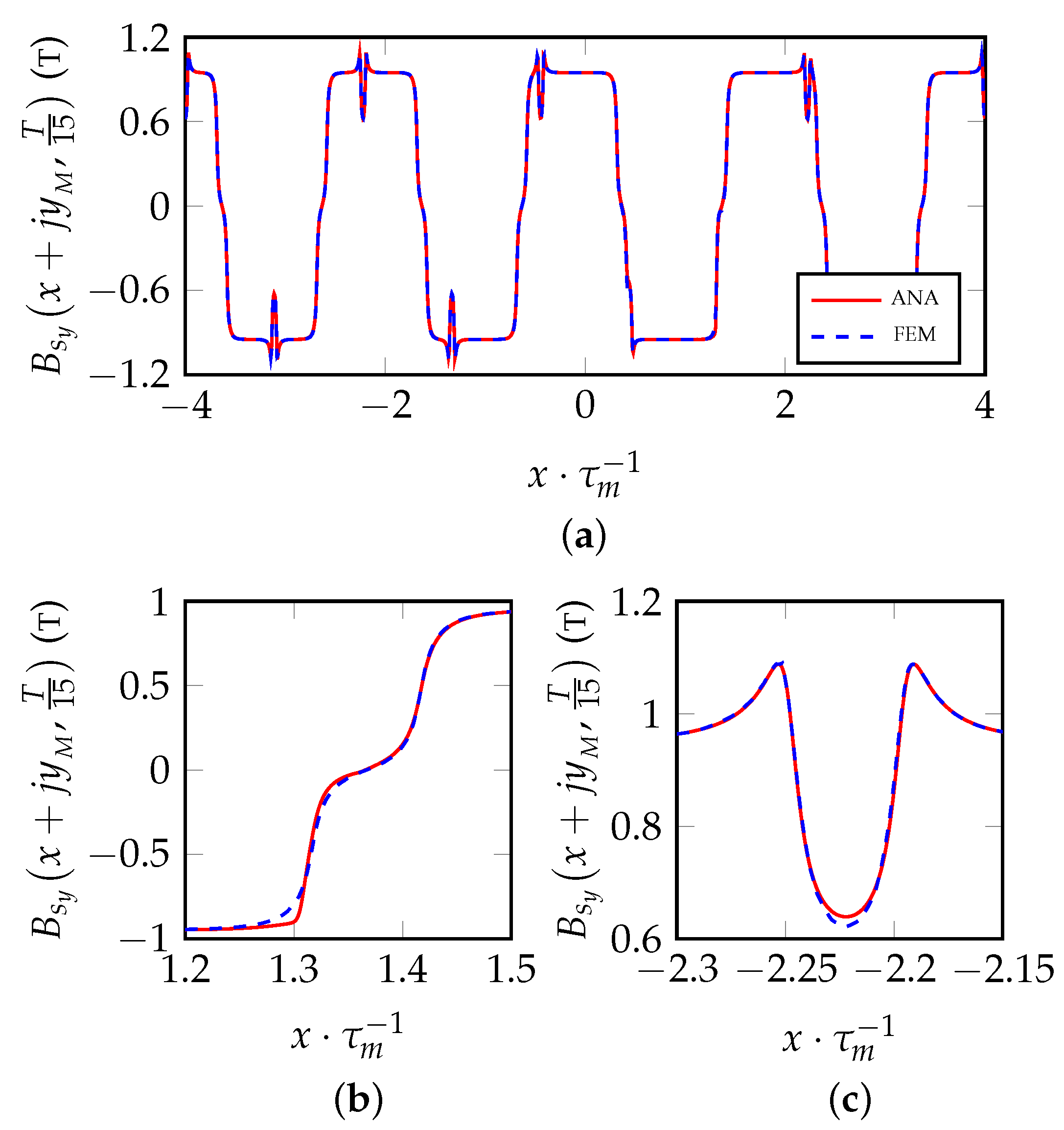
in which the term ( 1 ) k justifies the presence of the alternating north and south adjacent polarities. Figure 6a,b shows the flux density distributions components of the total SPM model stated in (6) on the middle air-gap line in comparison with a magneto-static FEM simulation with infinitely permeable iron for a PM slider position corresponding to a time instant t = T/15 ( T = 16.67 ms).
Note that, the inequality between adjacent peaks for both the FEM and analytical patterns in Figure 6b isn’t real but just a plotting effect due to the spatial discretization of the machine periphery.

3. Magnetic Field in Case of Slotted Ferromagnetic Surfaces

3.1. Slot Opening Model

In the subsequent sections, the presence of the slot opening and its influence on the magnetic field distribution inside the air gap will be analyzed. Using the approach based on the solution in Fourier series of the Laplace equation [24], a unique and more compact expression of the complex relative air-gap permeance function is obtained, effective for any segment positioned inside the air-gap of the machine.
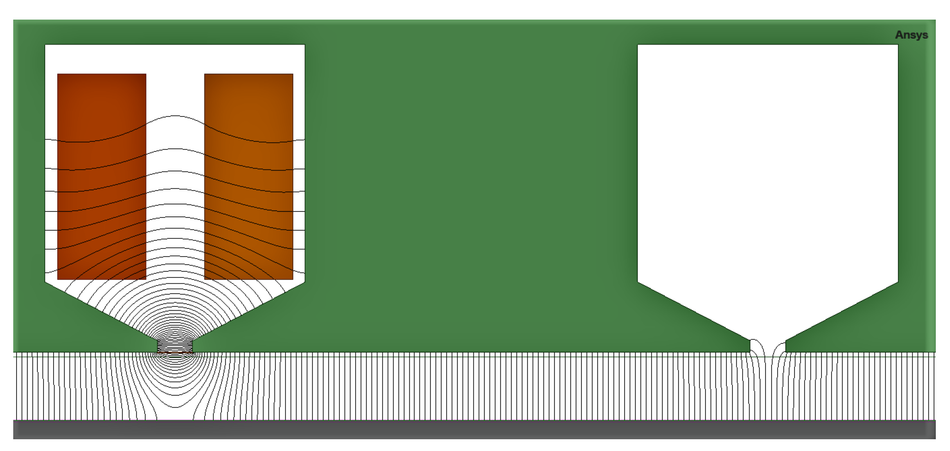
Figure 7 exhibits the flux lines map, produced by a slot with two rectangular energized active sides with a total slot m.m.f of constant value M s , inside a linear ferromagnetic slotted structure, for a slot opening size b s o = 6 mm.
The focus will be placed according to the classical theory on the area regarding the unenergized slot, the slot where the m.m.f contribute is null, being the energized slot area object of another work.
Considering a generic point z = x + j y inside the air-gap domain, it is possible to define a complex function β ( z ) = β x ( z ) + j β y ( z ) whose components are:
β y ( x + j y ) = B s y ( x + j y ) B i
β x ( x + j y ) = B s x ( x + j y ) B i
with B i = μ o M s / 2 g . Recalling the flux density vector B ( z ) between smooth iron surfaces the slotted flux density vector can be stated as:
B s ( z ) = λ ( z ) · B ( z )
where λ ( z ) is the relative complex permanence function [5]. Due to the fact that the slotless flux density vector has only the vertical component ( B ( z ) = j B i ) from (9):
λ ( z ) = B s ( z ) j B i = β y ( z ) j β x ( z ) = j β ( z ) .
Hence it is possible to define a complex slotting function β ( z ) which transforms the slotless flux density vector B ( z ) to a slotted vector according to:
B s ( z ) = j β ( z ) · B ( z )
and finally, starting from the approach explained in [24] and through some manipulations, the complex slotting function can be formulated as:
β ( z ) = n = 1 N h j α ( n ) sinh 2 π n g τ t cos 2 π n z ¯ τ t + ( 1 ) n k c 1 cos π n ( z z ¯ ) τ t n = 1 N h ( 1 ) n α ( n ) τ t 2 π n g + 1 k c 1 cos π n ( z z ¯ ) τ t sinh 2 π n g τ t α ( n ) = 0 ρ s o / 2 1 ρ s o / 2 ξ 3 1 ρ s o / 2 + ξ 3 sin ( 2 π n ξ ) d ξ .
This slotting complex function is periodic along the coordinate x over a machine tooth pitch τ t and in respect to [24] it has the advantage to be just one compact complex formula generalized for a generic complex point z = x + j y within the air-gap domain.
Now bringing the attention to the schematic shown below in Figure 8, where a generic exploration segment γ e is horizontally positioned at y e in the range 0 y e g , the slotted flux density vector along segment γ e can be obtained as follows:
B s ( x + j y e ) = j β ( x + j y e ) · B ( x + j y e ) .
Figure 9a,b show the p.u. flux density distributions retrieved with (12) compared with the FEM on an horizontal segment at y = y M in front of a slot opening b s o = 6 mm.

3.2. Magnetic Field due to a Sequence of Permanent Magnets for Slotted Surfaces

It will be now taken into consideration the slotted machine pictured in Figure 5a where is filled with iron and is filled with air. In Section 3.1 the behavior of the flux density vector inside the mechanical air-gap, in proximity of an unpowered slot has been investigated, defining a complex slotting function analogous to the complex permeance function. As soon as the value of the exploration coordinate is chosen, the slotted flux density vector on the horizontal line at y = y e as a function of time can be retrieved:
B s ( x + j y e , t ) = j β ( x + τ t / 2 + j y e ) · B ( x + j y e , t )
with (12) also taken along a horizontal line at y = y e shifted by τ t / 2 to align with the coordinate system of Figure 5a. It can be easily noticed that, being the slot opening of the linear machine positioned on the stator, the complex slotting function is fixed and does not depend on time.
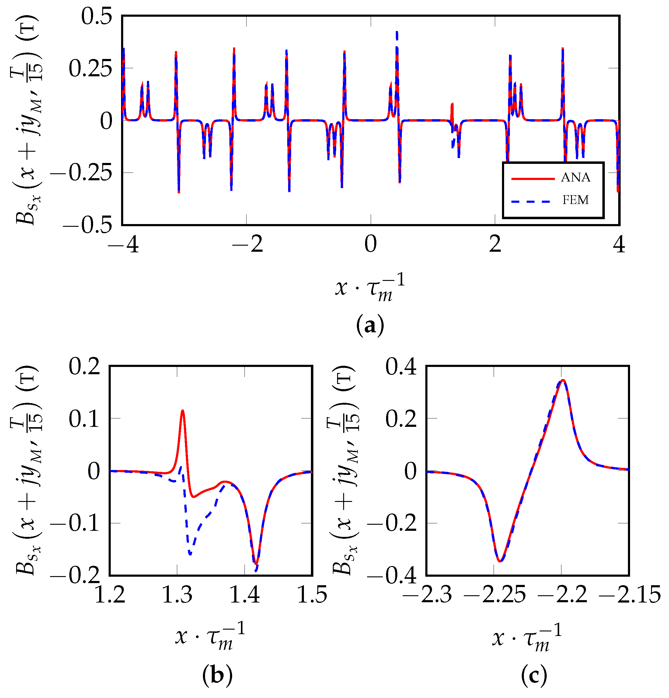
Figure 10a and Figure 11b show the normal and tangential flux density distributions on the middle air-gap line z = x + j y M for a time instant t = T / 15 , where t = 0 corresponds to the time in which the north magnet (white color PM in Figure 5a is aligned with the central tooth n t h = 5 .
The analytical pattern is perfectly superimposed almost everywhere to the FEM one, except in some areas where the two patterns slightly differ from each other, as it can be seen in Figure 10b and Figure 11b. The reason is explained by the fact that, in the area of interest, a magnet edge lies in front of the slot opening, slightly modifying, because of fringing, the flux lines patterns from the ideal ones represented by the slot opening complex function. Notice that the method here presented models the no-load air-gap flux density pattern of a machine with semi-closed slots but it can be applied to model the air-gap flux density of machines with open slots as well.

4. Complex Integral Quantities

4.1. Complex Vectors and Mechanical Actions

In the antecedent sections, the analytical expression of the magnetic field inside the air gap of a smooth infinitely permeable iron machine has been introduced and subsequently, by the use of (12), the complex slotting function was obtained to account for the presence of the slots. Now being aware of the analytical field distribution, into the air-gap domain, it is possible to determine integral quantities like magnetic fluxes and mechanical forces. Here attention will be devoted only to the mechanical forces generated inside the machine.
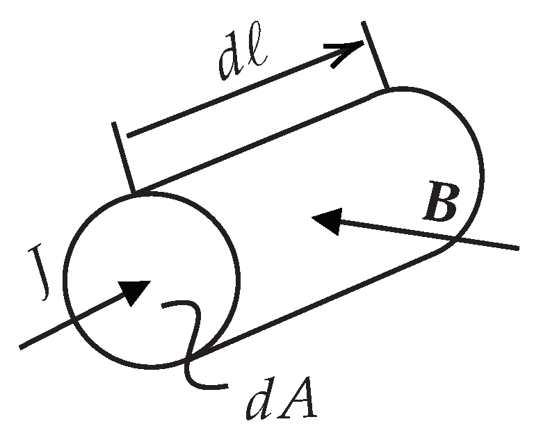
Let’s consider the infinitesimal portion of a conductor, with infinitesimal cross-section d A and length d , immersed in a magnetic field and powered by a current density J shown in Figure 12.
Writing the well-known Lorenz’s expression, the infinitesimal contribution of force acting on the conductor is:
d F = J d A d × B .
Moving the vector information from the vector infinitesimal element d to the current density J and dividing by the infinitesimal volume d v = d A d allows to write:
d F d v = J × B = ( × H ) × B
which is the expression of the force per unit volume, that, integrated over the conductor volume, gives the entire mechanical force acting on it. Consequently (16) can be integrated in the volume of interest:
F = V ( × H ) × B d v .
Because the field is planar, lying entirely on the x y plane, (17) can be written as a surface integral over the area of interest A multiplied by the axial length :
F = · A ( × H ) × B d A .
At this stage, before to proceed with further manipulations of the aforementioned equations, a small mathematical statement must be postulated:
Considering a generic complex vector W ( z ( x , y ) ) = W x + j W y , lying on the x y plane and z ¯ = x j y , being the conjugate of a generic complex point z, being z ¯ x = 1 and z ¯ y = j it is possible to write:
W ( z ( x , y ) ) x = W z ¯ · z ¯ x = W z ¯ W ( z ( x , y ) ) y = W z ¯ · z ¯ y = j W z ¯
and from (19a):
2 W z ¯ = W x + j W y 2 z ¯ = x + j y .
Introducing another generic complex vector Ω ( z ( x , y ) ) = Ω x + j Ω y , function of the complex variable z it can be demonstrated that:
Ω ¯ W = Re { Ω ¯ W } + j Im { Ω ¯ W } = Ω · W + j | Ω × W |
thus looking at (19b) and (19c), setting Ω = , the curl and divergence of the generic complex vector W can be expressed as follows:
· W = x + j y · ( W x + j W y ) = 2 z ¯ · W = Re 2 W z
| × W | = | x + j y × ( W x + j W y ) | = | 2 z ¯ × W | = Im 2 W z .
Then, according to what is stated above in (19d) and (19e), the divergence and curl of the vector H can be expressed as the real and imaginary part of twice the derivative of H in respect to z:
· H = Re 2 H z
× H = Im 2 H z k ^
where k ^ is the versor of the axis perpendicular to the complex plane. However, due to the solenoidal property of the field and being inside a constant permeability medium (air), (20) equals zero and the derivative of H in respect to z is purely imaginary:
2 H z = j Im 2 H z
consequently (16) can be stated as:
d F d v = Im 2 H z k ^ × B = j 2 H z k ^ × B = 2 B 2 2 μ o z .
Finally by the use of (23), remembering the property explained in (19a)–(19e) the total force acting on the conductor expressed into (18) can be stated as a force per unit length F = F / as follows:
F = A · B 2 2 μ o d A + j A | × B 2 2 μ o | d A .
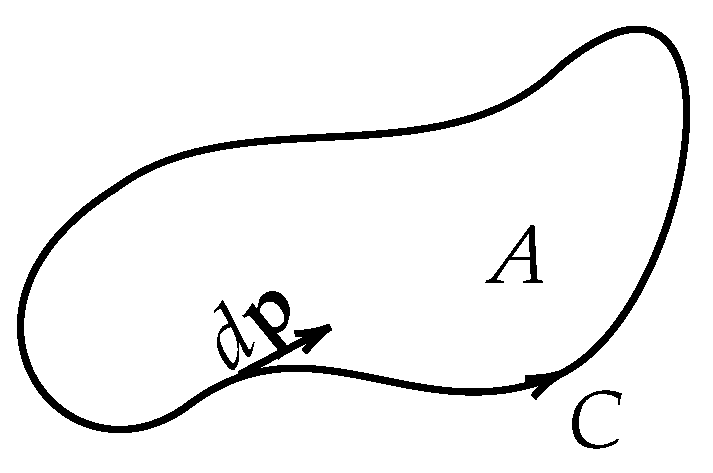
If the generic closed curve C oriented counterclockwise shown in Figure 13 is taken, by applying the divergence and curl theorem:
F = C | B 2 2 μ o × d p | + j C B 2 2 μ o · d p
= C Im B 2 2 μ o ¯ d p + j C Re B 2 2 μ o ¯ d p = j C B 2 ¯ 2 μ o d p
wherein the first term on the first line of (25) is the flux of B 2 / ( 2 μ o ) across C and the second term is the circulation of B 2 / ( 2 μ o ) along C respectively. Then the final expression of the complex force vector per unit length is obtained. The quantity B 2 ¯ / ( 2 μ o ) is the conjugate of the flux density vector squared, divided by twice the permeability of vacuum. Finally deriving (25) in respect to d p the Maxwell stress complex tensor expression can be retrieved:
σ = d F d p = j B 2 ¯ 2 μ o .
It is worth mentioning that the equations described in this subsection are of general validity, also with currents flowing in the stator windings.

4.2. Maxwell Stress Complex Tensor and Forces

The Maxwell stress tensor is used in classical electromagnetism to calculate forces; the volume integral of J × B , throughout some mathematical manipulations is reduced to a surface integral of the stress tensor valid for any enclosing surface in the air of the considered volume, simplifying the calculations. If, into (26) the slotted flux density vector stated in (14) is inserted, it is possible to write:
σ s ( z , t ) = j B s ( z , t ) 2 ¯ 2 μ o
obtaining the Maxwell tensor complex expression, the function of time for the slotted configuration. Figure 14a,b show the normal and tangential components of the Maxwell tensor on the middle mechanical air-gap line at y = y M and t = T / 15 in comparison with FEM.
As concerns the calculation of the forces per unit length, there are two different targets:
  • evaluation of the forces applied to each tooth, typically considered in NVH calculations;
  • evaluation of the forces applied to the global system.
With reference to the linear system of Figure 5a, the force on the tooth n t h can be expressed as:
F n th ( t ) = x n t h τ t 2 x n t h + τ t 2 σ s ( x + j y M , t ) d x
Equation (28) is integrated on the position y = y M , on the middle mechanical air-gap line, over the tooth pitch of the n t h tooth, centered on the tooth axis x n t h value, with n t h = 1 , 2 , , N t h . The real part and imaginary part of (28) represent the tangential and normal components of the force per unit length acting on the n t h tooth tip. The force applied to the global stator can be written as:
F ( t ) = N t h 2 τ t N t h 2 τ t σ s ( x + j y M , t ) d x
but it can also be expressed in the following manner:
F ( t ) = n t h = 1 N t h F n th t .
Equations (27)–(30) have general validity, also in case of flowing currents in the stator windings. If (28) is applied to the central tooth n t h = 5 under no load conditions, the normal and tangential forces per unit length are the ones shown in Figure 15.
The following remarks can be highlighted:
  • FEM and analytical waveforms are in fair agreement;
  • the normal component amplitude is predominant with respect to the tangential one;
  • the force waveform acting on a generic tooth tip has a frequency that is double the fundamental frequency ( 1 / T ).
It can be realized that the no load force waveforms are equal for each tooth tip but shifted in time by a quantity multiple of T · τ t / ( 2 τ m ) . It is possible then to calculate the total force acting on the stator structure from (28) referred to a single machine tooth tip; for convenience the tooth whose axis is aligned with the y axis of the reference frame n t h = 5 :
F o ( t ) = n t h = 1 N t h F 5 t + ( n t h 5 ) · τ t 2 τ m T
wherein the real part F o x ( t ) = Re { F o ( t ) } and imaginary part F o y ( t ) = Im { F o ( t ) } represent the tangential and normal components of the force per unit length acting on the stator structure, under no load conditions, at a generic time instant t. Computing (31) for N t samples of time with 0 t T , allows us to retrieve a transient analytical calculation of the machine’s instantaneous force acting on the stator. Figure 16a,b show the normal and tangential component of (31) over a period of the cogging force, which corresponds to 1 / 18 of the electrical period T.
The following considerations can be done:
  • the diagrams shown in Figure 16a,b in which both analytical and FEM calculations are based on Maxwell tensor, can be also obtained using (29);
  • (29) implies a greater computation time in respect to (31) due to a wider spacial integration interval;
  • on this peripheral extension, corresponding to the space period, FEM calculation can be also performed by using the Virtual Work Principle;
  • the analytically calculated normal component shows a better agreement with respect to the FEM result;
  • a wider difference appears for the tangential component: the reason for that could be a massive difference in the order of magnitude of these two components, making the numerical noise error predominant in the analytical calculation of the minor quantity; moreover, the tangent component calculation is affected by local inaccuracies due to fringing effect as shown in Figure 11b.
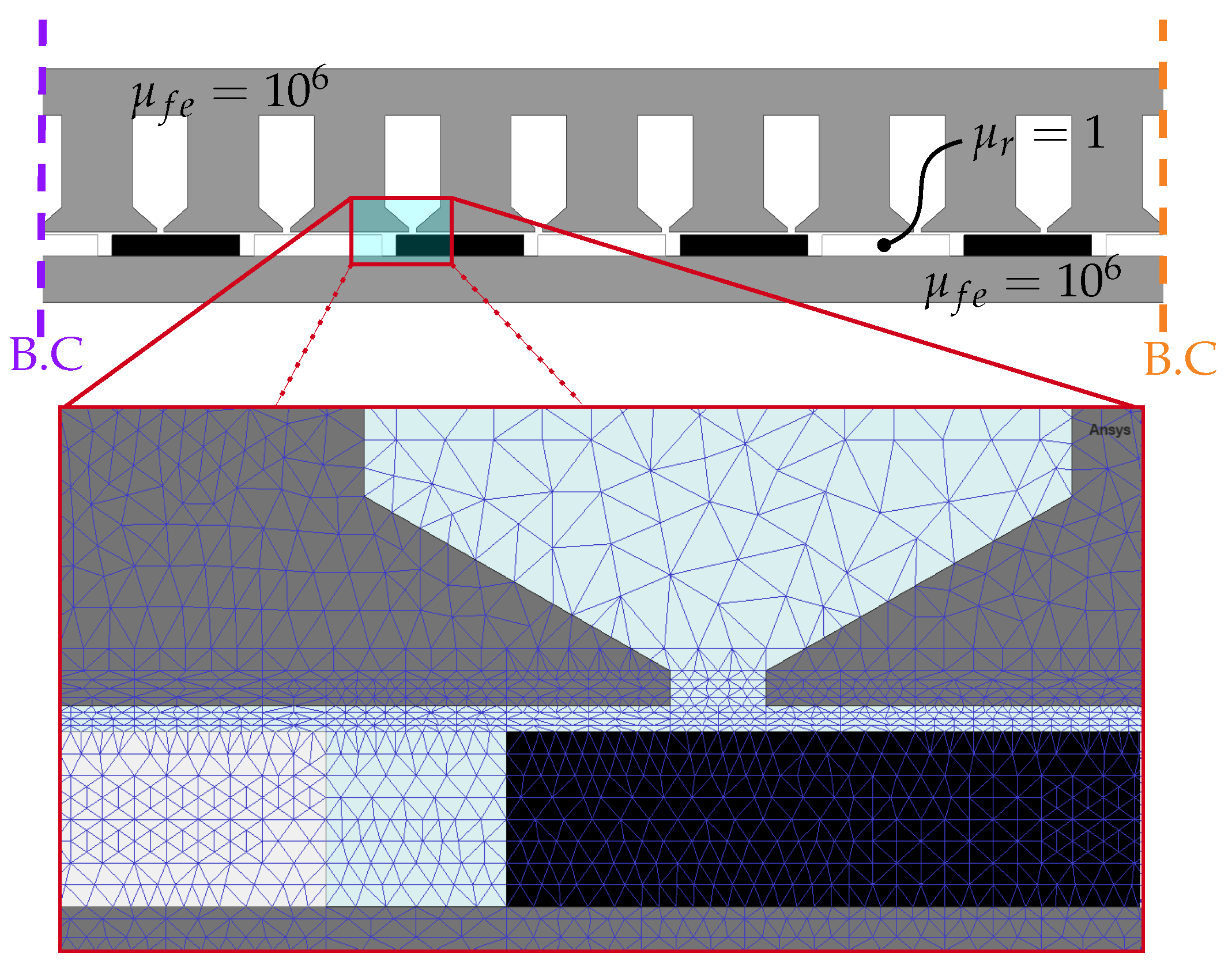
Figure 17 shows the FEM model at t = 0 which has been used in order to validate the introduced analytical model together with a picture of the mesh inside the equivalent air-gap region. The two dotted lines B.C. indicate the boundary conditions that allow us to obtain periodicity in the field patterns. With the aim of carrying out an equal comparison of the introduced model with the numerical one, the relative recoil permeability of the PMs of the FEM model was set to one ( μ r = 1 ) and both the rotor and iron relative permeabilities were set to a very high numerical value ( μ f e = 10 6 ) to recreate, numerically speaking, the theoretical condition of infinite iron permeability and neglect the saturation effect. Magnetic saturation is not included in the model described in this paper, but already developed procedures demonstrated that the field in the air gap under saturated conditions can be obtained starting from the unsaturated distribution using suited correcting coefficients.

4.3. Computational Efficiency

The time required by the analytical and FEM for the calculation of forces is now compared. Table 2 shows the time necessary to compute (29) and (31) with respect to transient FEM simulations using the Virtual Work Principle (VWP) and the Maxwell tensor (MT).
The calculator is an i7-10850H @ 2.70GHz 32GB RAM, the analytical model has been implemented using MATLAB R2019b while the FEM simulations have been carried out with Ansys Electronics Desktop 2021 R2. In the FEM environment, the entire portion of the machine periphery has to be modeled, due to the fact that τ t and τ m are not equal no smaller equivalent models exploiting spatial periodicity can be used. The FEM MT requires a much higher computational time with respect to the FEM VWP because, for each time step of the simulation, the field map must be saved. Both the analytical methods are faster than FEM and comparing the slowest analytical (ANA1) with the fastest FEM (FEM VWP), analytical is more than 100 times faster. This makes the presented method a good choice for an easily implemented and fast analytical calculation of the forces acting on the machine under no load conditions, opening also the possibility to develop future models for the study of the armature reaction and the on load condition.

5. Conclusions

The presented paper introduces a new method to analyze the flux density generated into the air gap of an SPM machine under no-load conditions. Starting from the model of a single conductor between two smooth iron surfaces, the analytical formulation of two vertical parallel current sheets have been retrieved and used to model an SPM, showing a very good agreement with magneto-static FEM simulations, for the slotless machine but also, after the application of the slotting function, for the slotted machine.
Subsequently, the parameter time has been introduced into the model; and the Maxwell tensor in the complex formulation has been retrieved starting from Lorentz’s force equation, adding the possibility to calculate the motor total forces, by the integration of the complex tensor along the middle air-gap machine periphery using two different approaches.
The proposed method is applied to a classical SPM configuration although it works very well for more complex PM configurations too, like the Halbach one, as it will be shown in future work. Future research will focus on the slotting function in front of the energized slots and will aim to deal with saturation and leakage which is one of the main limitations of the proposed model, especially under loaded conditions. By using conformal mapping, the method will be adapted to cylindrical machines. Moreover, saturated conditions will be modeled by suited correction factors that, applied to unsaturated air-gap flux density distributions, give the saturated ones.

Author Contributions

Conceptualization, A.D.G. and C.R.; methodology, A.D.G. and C.R.; software, A.D.G. and C.R.; validation, C.R.; formal analysis, A.D.G.; investigation, A.D.G. and C.R.; resources, A.D.G.; data curation, C.R.; writing—original draft preparation, C.R.; writing—review and editing, A.D.G. and C.R.; visualization, C.R.; supervision, A.D.G. All authors have read and agreed to the published version of the manuscript.

Funding

This research received no external funding.

Data Availability Statement

Not applicable.

Conflicts of Interest

The authors declare no conflict of interest.

Nomenclature

b m , α m PM peripheral size, p.u. ratio b m τ m .
b p s tooth tip peripheral size.
b s , b s o slot, slot opening peripheral size.
B c , B cs , B PM conductor, vertical current sheet, SPM double current sheet flux density complex vector.
B , B s smooth (slotless), slotted flux density complex vector.
B r , H o , μ r , PM residual flux density, linearly extrapolated coercivity, relative recoil permeability.
B i ideal flux density flat profile reference value.
F , F , σ force, force per unit length, Maxwell Tensor complex vector.
H magnetic field strength complex vector.
h m , δ , g PM, mechanical air-gap, equivalent air-gap height.
h c s current sheet length.
h p s , h s , h s o tooth tip, slot, slot opening height.
I , Δ , J conductor current, linear current sheet, vector current density.
k c Carter’s factor.
lamination stack length.
M s total slot m.m.f.
N t , N x , N h N° of time samples, spatial samples, slotting function harmonics.
N t h , N m N° of stator teeth, permanent magnets.
n t h N° of stator teeth counted from left to right.
Uideal magnetic voltage drop.
t , T parameter time, electrical period.
W x , W y generic vector tangential and normal component.
y e , y M exploration coordinate inside the air-gap, middle air-gap y coordinate g δ / 2 .
z p , z ¯ p generic point p of complex coordinates x p + j y p where the conductor is positioned and its conjugate.
z , z ¯ generic point of coordinate x + j y inside the air-gap complex plane and its conjugate.
β ( z ) , λ ( z ) slotting, permeance complex function.
γ e , γ M generic exploration segment at y = y e , middle mechanical air-gap segment at y = y M inside the air-gap.
ξ , ρ s o p.u. ratios x / τ t and b s o / τ t .
τ m , τ t PM pitch, tooth pitch.

References

  1. Liu, Y.X.; Li, L.Y.; Gao, Q.H.; Cao, J.W.; Wang, R.H.; Sun, Z.Y. Analytical Model of Torque-Prediction for a Novel Hybrid Rotor Permanent Magnet Machines. IEEE Access 2019, 7, 109528–109538. [Google Scholar] [CrossRef]
  2. Alam, F.R.; Abbaszadeh, K. Magnetic Field Analysis in Eccentric Surface-Mounted Permanent-Magnet Motors Using an Improved Conformal Mapping Method. IEEE Trans. Energy Convers. 2016, 31, 333–344. [Google Scholar] [CrossRef]
  3. Zhu, Z.; Howe, D.; Bolte, E.; Ackermann, B. Instantaneous magnetic field distribution in brushless permanent magnet DC motors. I. Open-circuit field. IEEE Trans. Magn. 1993, 29, 124–135. [Google Scholar] [CrossRef]
  4. Zhu, Z.; Howe, D. Instantaneous magnetic field distribution in brushless permanent magnet DC motors. III. Effect of stator slotting. IEEE Trans. Magn. 1993, 29, 143–151. [Google Scholar] [CrossRef]
  5. Zarko, D.; Ban, D.; Lipo, T. Analytical calculation of magnetic field distribution in the slotted air gap of a surface permanent-magnet motor using complex relative air-gap permeance. IEEE Trans. Magn. 2006, 42, 1828–1837. [Google Scholar] [CrossRef]
  6. Zarko, D.; Ban, D.; Lipo, T.A. Analytical Solution for Cogging Torque in Surface Permanent-Magnet Motors Using Conformal Mapping. IEEE Trans. Magn. 2008, 44, 52–65. [Google Scholar] [CrossRef]
  7. Heller, B.; Hamata, V. Harmonic Field Effects in Induction Machines; Elsevier Scientific: New York, NY, USA, 1977. [Google Scholar]
  8. Wang, X.; Li, Q.; Wang, S.; Li, Q. Analytical calculation of air-gap magnetic field distribution and instantaneous characteristics of brushless DC motors. IEEE Trans. Energy Convers. 2003, 18, 424–432. [Google Scholar] [CrossRef]
  9. Min, S.G.; Sarlioglu, B. Modeling and Investigation on Electromagnetic Noise in PM Motors with Single- and Double-Layer Concentrated Winding for EV and HEV Application. IEEE Trans. Transp. Electrif. 2018, 4, 292–302. [Google Scholar] [CrossRef]
  10. Wang, H.; Liu, K.; Wei, J.; Hu, H. Analytical Modeling of Air Gap Magnetic Fields and Bearing Force of a Novel Hybrid Magnetic Thrust Bearing. IEEE Trans. Magn. 2021, 57, 1–7. [Google Scholar] [CrossRef]
  11. Geng, H.; Zhang, X.; Yan, S.; Zhang, Y.; Wang, L.; Han, Y.; Wang, W. Magnetic Field Analysis of an Inner-Mounted Permanent Magnet Synchronous Motor for New Energy Vehicles. Energies 2022, 15, 4074. [Google Scholar] [CrossRef]
  12. Guo, R.; Yu, H.; Xia, T.; Shi, Z.; Zhong, W.; Liu, X. A Simplified Subdomain Analytical Model for the Design and Analysis of a Tubular Linear Permanent Magnet Oscillation Generator. IEEE Access 2018, 6, 42355–42367. [Google Scholar] [CrossRef]
  13. Akcay, Y.; Giangrande, P.; Tweedy, O.; Galea, M. Fast and Accurate 2D Analytical Subdomain Method for Coaxial Magnetic Coupling Analysis. Energies 2021, 14, 4656. [Google Scholar] [CrossRef]
  14. Wu, L.J.; Zhu, Z.Q.; Staton, D.; Popescu, M.; Hawkins, D. Comparison of analytical models for predicting cogging torque in surface-mounted PM machines. In Proceedings of the XIX International Conference on Electrical Machines—ICEM 2010, Rome, Italy, 6–8 September 2010; pp. 1–6. [Google Scholar] [CrossRef]
  15. Jiang, H.; Su, Z.; Wang, D. Analytical Calculation of Active Magnetic Bearing Based on Distributed Magnetic Circuit Method. IEEE Trans. Energy Convers. 2021, 36, 1841–1851. [Google Scholar] [CrossRef]
  16. Hu, W.; Zhang, X.; Yin, H.; Geng, H.; Zhang, Y.; Shi, L. Analysis of Magnetic Field and Electromagnetic Performance of a New Hybrid Excitation Synchronous Motor with dual-V type Magnets. Energies 2020, 13, 1501. [Google Scholar] [CrossRef] [Green Version]
  17. Tong, W.; Wang, S.; Wu, S.; Tang, R. A Complete Quasi-3-D Analytical Model of No-Load Magnetic Field of Double-Sided Slotted AFPMMs Considering End Effect. IEEE Access 2018, 6, 59557–59566. [Google Scholar] [CrossRef]
  18. Guo, B.; Huang, Y.; Peng, F.; Dong, J. A New Hybrid Method for Magnetic Field Calculation in IPMSM Accounting for Any Rotor Configuration. IEEE Trans. Ind. Electron. 2019, 66, 5015–5024. [Google Scholar] [CrossRef] [Green Version]
  19. Cao, Z.; Huang, Y.; Guo, B.; Peng, F.; Dong, J.; Hemeida, A. A Novel Hybrid Analytical Model of Active Magnetic Bearing Considering Rotor Eccentricity and Local Saturation Effect. IEEE Trans. Ind. Electron. 2022, 69, 7151–7160. [Google Scholar] [CrossRef]
  20. Chan, T.F.; Lai, L.L. Computation of air-gap field in an axial-flux permanent-magnet machine using the method of images. In Proceedings of the 2009 IEEE International Electric Machines and Drives Conference, Miami, FL, USA, 3–6 May 2009; pp. 1647–1651. [Google Scholar] [CrossRef]
  21. Kou, B.; Zhang, H.; Li, L. Analysis and Design of a Novel 3-DOF Lorentz-Force-Driven DC Planar Motor. IEEE Trans. Magn. 2011, 47, 2118–2126. [Google Scholar] [CrossRef]
  22. Hague, B. The Principles of Electromagnetism Applied to Electrical Machines; Dover: New York, NY, USA, 1962. [Google Scholar]
  23. Marković, M.; Jufer, M. Conformal mapping field determination in a motor with air gap excitation. In Proceedings of the Intern. Conf. on Electrical Machines (ICEM), Brugge, Belgium, 25–28 August 2002. [Google Scholar]
  24. Tessarolo, A.; Olivo, M. A new method for the analytical determination of the complex relative permeance function in linear electric machines with slotted air gap. In Proceedings of the 2016 International Symposium on Power Electronics, Electrical Drives, Automation and Motion (SPEEDAM), Capri, Italy, 22–24 June 2016; pp. 1330–1335. [Google Scholar] [CrossRef]
  25. Rassõlkin, A.; Kallaste, A.; Orlova, S.; Gevorkov, L.; Vaimann, T.; Belahcen, A. Re-Use and Recycling of Different Electrical Machines. Latv. J. Phys. Tech. Sci. 2018, 55, 13–23. [Google Scholar] [CrossRef] [Green Version]
  26. Grenier, J.M.; Pérez, R.; Picard, M.; Cros, J. Magnetic FEA Direct Optimization of High-Power Density, Halbach Array Permanent Magnet Electric Motors. Energies 2021, 14, 5939. [Google Scholar] [CrossRef]
  27. Li, B.; Zhang, J.; Zhao, X.; Liu, B.; Dong, H. Research on Air Gap Magnetic Field Characteristics of Trapezoidal Halbach Permanent Magnet Linear Synchronous Motor Based on Improved Equivalent Surface Current Method. Energies 2023, 16, 793. [Google Scholar] [CrossRef]
  28. Di Gerlando, A.; Foglia, G.; Ricca, C. Analytical Design of a High Torque Density In-Wheel YASA AFPM Motor. In Proceedings of the 2020 International Conference on Electrical Machines (ICEM), Gothenburg, Sweden, 23–26 August 2020; Volume 1, pp. 402–408. [Google Scholar] [CrossRef]
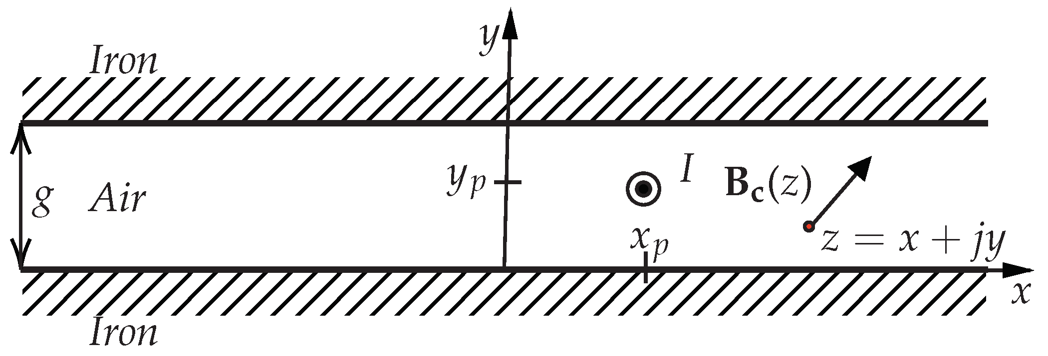
Figure 1. Conductor powered by a current I, flowing outwards the paper plane, between two smooth infinitely permeable iron surfaces, in the complex plane.
Energies 16 03197 g001
Figure 2. Vertically oriented current sheet of length h c s , powered by a current density Δ flowing outwards the paper plane, whose extremes are situated at z p 1 and z p 2 between two smooth iron surfaces ( g = 11.5 mm and δ = 1.5 mm).
Energies 16 03197 g002
Figure 3. Analytical and FEM flux density distributions, on the middle mechanical air-gap line, caused by an SPM between two smooth iron surfaces ( b m x b m   N x = 1000 ). (a) p.u. normal; (b) tangential component.
Energies 16 03197 g003
Figure 4. Analytical and FEM flux density distributions on the middle PM line, caused by an SPM between two smooth iron surfaces ( b m x b m   N x = 1000 ). (a) p.u. normal; (b) tangential component.
Energies 16 03197 g004
Figure 5. (a) Machine case of study: (1) slotless: zones and both filled with iron; (2) slotted: zone filled with iron and with air. (b) Zoom with main sizes.
Energies 16 03197 g005
Figure 6. Analytical and FEM no-load flux density distributions on the middle mechanical air-gap line of the slotless machine of Figure 5a, with PM slider position corresponding to a time instant t = T/15 ( 4 τ m x 4 τ m   N x = 1000 ). (a) normal; (b) tangential component.
Energies 16 03197 g006
Figure 7. Flux lines inside energized and not energized slot (slot opening b s o = 6 mm). Even if not shown in the figure, the magnetic structure is symmetrical with respect to the energized slot axis.
Energies 16 03197 g007
Figure 8. Slotted air-gap with generic segment γ e ( τ t / 2 x τ t / 2 ).
Energies 16 03197 g008
Figure 9. Analytical and FEM no-load flux density p.u. (a) normal and (b) tangential component on the middle mechanical air-gap line at y e = y M ( 1 / 5 τ t x 1 / 5 τ t   N x = 1000 , N h = 150 ).
Energies 16 03197 g009
Figure 10. Analytical and FEM no-load flux density normal component on the middle mechanical air-gap line of the slotted machine of Figure 5a, with PM slider position corresponding to a time instant t = T/15 ( 4 τ m x 4 τ m   N x = 1000 , N h = 150 ); (b,c) are two different selective zooms of (a).
Energies 16 03197 g010
Figure 11. Analytical and FEM no-load flux density tangential component on the middle mechanical air-gap line of the slotted machine of Figure 5a, with PM slider position corresponding to a time instant t = T/15 ( 4 τ m x 4 τ m   N x = 1000 , N h = 150 ); (b,c) are two different selective zooms of (a).
Energies 16 03197 g011
Figure 12. Infinitesimal conductor portion powered by a current density J immersed in a magnetic field of flux density value B .
Energies 16 03197 g012
Figure 13. Generic closed curve C inside the complex plane embracing an area A.
Energies 16 03197 g013
Figure 14. Analytical and FEM no load Maxwell tensor distributions on the middle mechanical air-gap line of the slotted machine of Figure 5a, with PM slider position corresponding to a time instant t = T/15 ( 4 τ m x 4 τ m   N x = 1000 , N h = 150 ). (a) normal; (b) tangential component.
Energies 16 03197 g014
Figure 15. Analytical and FEM force per unit length F 5 ( t ) ( 0 t T / 2   N t = 120 ) (a) normal; (b) tangential component. FEM curve obtained using the Maxwell tensor.
Energies 16 03197 g015
Figure 16. Analytical and FEM no load force per unit length of the slotted machine of Figure 5a ( 0 t T / 18   N t = 120 ). (a) normal component; (b) tangential component. The analytical calculation was based on (31) and FEM curve was calculated using the Maxwell tensor.
Energies 16 03197 g016
Figure 17. FEM model of the machine case of study and selective zoom of the mesh inside the equivalent air-gap region.
Energies 16 03197 g017
Table 1. Machine Main Data.
Parameters
residual flux density, B r 1.1 T
N° of teeth, N t h ; N° of PM, N m 9; 8
PM pitch, τ m ; p.u. ratio, α m 113.39 mm; 0.9
PM height, h m ; air-gap height, δ 10 mm; 1.5 mm
slot height, h s ; slot width, b s 20.5 mm; 44.3 mm
tooth tip height, h s o ; slot opening width, b s o 2 mm; 6 mm
pole shoe height, h p s ; pole shoe width, b p s 12 mm; 94.79 mm
stack length, 61.25 mm
Table 2. Computational Time.
MethodTime
ANA1 (29) N h = 150 ,
4 τ m x 4 τ m   N x = 10 , 000 ,3.2 s
0 t T / 18   N t = 120 ,
ANA2 (31) N h = 150 ,
1 / 2 τ t x 1 / 2 τ t   N x = 1111 ,0.36 s
0 t T / 2   N t = 120 ,
FEM VWP
0 t T / 18   N t = 120 ,5.5 min
FEM MT
0 t T / 18   N t = 120 ,20.6 min
N° of mesh triangles in the different parts inside the machine:
stator: 2100, slider: 1600,
air-gap: 12,000, slots: 300, PMs: 10,800
Disclaimer/Publisher’s Note: The statements, opinions and data contained in all publications are solely those of the individual author(s) and contributor(s) and not of MDPI and/or the editor(s). MDPI and/or the editor(s) disclaim responsibility for any injury to people or property resulting from any ideas, methods, instructions or products referred to in the content.