Abstract
The torque ripples in a switched reluctance motor (SRM) are minimized via an optimal adaptive dynamic regulator that is presented in this research. A novel reinforcement neural network learning approach based on machine learning is adopted to find the best solution for the tracking problem of the SRM drive in real time. The reference signal model which minimizes the torque pulsations is combined with tracking error to construct the augmented structure of the SRM drive. A discounted cost function for the augmented SRM model is described to assess the tracking performance of the signal. In order to track the optimal trajectory, a neural network (NN)-based RL approach has been developed. This method achieves the optimal tracking response to the Hamilton–Jacobi–Bellman (HJB) equation for a nonlinear tracking system. To do so, two neural networks (NNs) have been trained online individually to acquire the best control policy to allow tracking performance for the motor. Simulation findings have been undertaken for SRM to confirm the viability of the suggested control strategy.
1. Introduction
Recently, the deployment of Switched Reluctance Motors (SRMs) in a vast scope of car electrification and variable speed systems has garnered significant recognition. The SRM is a flexible contender that might outperform other types of machines due to its inherent durability, fault-tolerant capability, affordable pricing, and natural simplicity due to its lack of magnets, brushes, and winding of a rotor [1,2]. Advancements in power electronic devices and computer programming have increased their efficiency. SRMs are now being considered for a number of applications requiring high-speed performance and dependability, including those involving electric vehicles and aviation [3,4,5,6,7]. SRMs have numerous benefits, but they also have certain drawbacks, such as huge torque ripples that might result in loud noise and vibration when the motor is operating. The system’s nonlinear electromechanical characteristic, which depends on current and rotor angle, as well as severe magnetic saturation, to achieve great torque density, is the cause of the torque ripples. As a result, extending the percentage of SRM in high-performance models requires reducing the torque’s oscillations.
To limit torque ripples, there are two common approaches that have been employed. The first entails improving the machine’s magnetic configuration [8,9,10,11]. In one instance, the rotor and stator structures were changed by the SRM’s manufacturer to reduce torque ripples; however, this might have degraded efficiency [12]. The second alternative is designing a torque regulator to minimize ripples and address the model’s nonlinearity. The SRM’s stator current ought to be precisely supplied and adjusted by the controller at the right rotor angle, as well as achieving the current pulses’ quick rise and fall times. This can be accomplished be inserting a considerable level of voltage from the DC supply to handle the back electromotive force which occurs during the operating of the machine and simultaneously minify the inductance per phase. That is, as the rotor speed rises, the induced voltage of the motor reaches a point at which the DC voltage pulses currently produced are inadequate to control the torque. In order to reach the highest possible voltage for high performance, the control mechanism would necessarily assume an optimum phase-pulse mode which requires a high switching frequency. As a result, having a controller with reduced torque fluctuations is a technical challenge for the SRM drive.
To relieve torque ripples, many strategies have been proposed. Bang–bang control, sliding mode techniques, and enhanced Proportional-Integral-Derivative (PID) control are several that are often used and simple to apply [13,14,15,16,17,18,19]. Bang–bang and delta-modulation regulators have typically been applied to regulate SRMs. For these mechanisms, a number of limitations, including significant torque pulsations, restricted switching frequency due to semiconductor properties, and variable switching frequency, which results in less effective regulation of Electro-Magnetic Interference (EMI) make them impracticable for many applications. In such a model, the current pulse cannot be adjusted speedily enough by the classical PID regulator. Indeed, even more advanced transitioning PID controllers are unable to provide the best response. Additionally, researchers have studied direct torque optimal control approaches. The direct instantaneous torque control (DITC) system can be used to cope with the difficulty to represent the phase current as a function of torque and rotor angles. Although DITC has a straightforward and easy structure, its implementation necessitates complicated switching rules, unrestrained switching frequency, and a very large sample rate [18,19,20,21,22,23,24,25,26]. Therefore, implementing a controller that can minimize the torque ripples requires a very high dynamic scheme which allows high switching frequency.
In this article, a machine learning algorithm using RL techniques is employed to track the reference signal and reduce pulsations on torque pulses of the SRM drive. This unique approach is able to handle the model variances and produce excellent results even though the SRM experiences nonlinearities dependent on current and rotor angles. In this approach, the SRM tracking problem needs to be solved by optimizing the tracking function and tracing reference trajectory. Dual-stream neural network strategies should be employed and trained to provide optimized duty cycles based on the predetermined utility function [27,28]. The nonlinear tracking Hamilton–Jacobi–Bellman (HJB) equation of SRM is determined by modulating the NNs until convergence, providing the tracking performance for the system model. The fundamental contributions of this research are as follows:
- I.
- Augmenting the SRM drive model to generate the tracking function;
- II.
- Adopting a policy iteration method based on a reinforcement learning algorithm to minimize the torque ripples of the SRM;
- III.
- Deployment of two NNs to optimize the HJB equation and conduct tracking operations for the system.
2. Materials and Methods
The main framework of the proposed model is shown in Figure 1, where the dual neural network architecture using the policy iteration method has been executed to minimize the torque ripples of the variable switched reluctance motor. The internal architecture of the proposed model is further described in the following subsection.
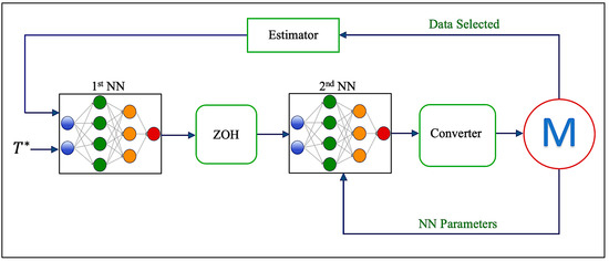
Figure 1.
The proposed framework for minimizing torque ripples.
2.1. Modelling the Tracking Function for Srm Drive
In machine learning theory, tracking control is a method used to guide the state of a system to follow a reference path, while the optimal regulation method aims to bring the system’s state dynamics to a halt [29]. The tracking control for an SRM drive is designed to align the machine’s output torque with the reference torque trajectory. Designing an optimum control system depends on being able to solve the partial differential equation known as the HJB equation, which represents the ideal control strategy for a nonlinear system. Optimal tracking control involves both feedforward and feedback control to accurately guide the system’s state towards a reference path while maintaining stability. Using the inverse dynamic technique, one may solve the feedforward portion that achieves tracking performance. By computing the HJB model, it is possible to conduct a feedback function that maintains the system’s stability. The authors of [30] discuss the typical responses for both concepts. The disadvantages of utilizing the usual approach are that it needs the inversion of the drive’s characteristics in order to derive the control policy and that it uses the full system’s parameters. Due to the complex nature of the controller, the typical solutions are consequently not applicable to SRM. To remedy this, the optimum tracking control of the SRM drive is intended to minimize a specified quadratic cost function based on the augmented system model that comprises the machine parameter and reference source model. This enhanced system requires that the reference signal is supplied and generated by a distinct source model. Reinforcement learning consists of a collection of techniques that enable the use of an expanded model in the construction of adaptive tracking control for a nonlinear system. These methods are intended to tackle the tracking issue online and in real time by monitoring data streams [27]. Enabling the controller to calculate the system dynamics and tracking the inaccuracies after each iteration is another method for estimating the inductance surface. All mathematical techniques need an estimator to update the model, which may then be applied to a controller such as model predictive control. Neural networks based on RL methods integrate adaptation and tracking performance simultaneously into a single task. Therefore, to benefit from this advantage while managing the non-linearity of the system, reinforcement dual-NN learning architecture is proposed for minimizing the torque ripples of the machine. By applying the neural network under the concept of value function approximator (VFA), this can approximate the cost function using the least-squares method. In optimal control, there are two techniques to solve the optimal tracking problem online in real time without requiring full knowledge of the system. One approach to RL is based on iterating the Q-function, which is called the Q-learning algorithm. However, this method is only applicable for the linear system. For nonlinear applications, another algorithm should be incorporated with Q-learning to cope with the nonlinearity of the system. The other approach of RL is the dual-neural-network architecture, which can solve the nonlinear system and be implemented for applications such as SRM. Therefore, the dual-neural-network architecture is a fundamental technique of reinforcement learning methods. This method includes two phases. The first NN is responsible for determining the optimum phase voltage of control input in the first stage of the process, which may be executed during the policy improvement phase. The second NN must assess the control input according to the policy evaluation step in the second stage.
Following is a discussion of the tracking issue for the dynamic model of the SRM drive and the derivation of the HJB equation.
2.1.1. Updated Model of SRM Drive
SRM consists of a variable number of salient poles on both the stator and the rotor of the motor. In order to generate the machine’s phases, the coils are wound around the stator pole and then installed in pairs that are mirror-opposite to one another. After the phase has been excited, the change in reluctances will cause the torque that is responsible for aligning the rotor pole with the stator poles. Because of its minimal impact on torque generation and dynamics, the mutual inductance between surrounding phases in an SRM is often quite low and has been omitted in the modeling process. In general, the mutual inductance between adjacent winding in an SRM is relatively tiny. As a consequence of this, the voltage and torque equation for one phase of an SRM may be expressed as
where is the phase resistance and is the flux linkage per phase computed by . is the inductance profile as a function of the rotor position ( and the phase current ( As seen in (2), the electromagnetic torque of a single phase is proportional to the square of the current in this type of machine. For this reason, the fundamental motivation for using the infinite-horizon tracking technique is to find the most suitable scheme for the system of SRM (1) that allows the output torque or the state to follow the reference trajectory . Subsequently, we can write out the error equation that leads to optimal tracking performance as
To develop the enhanced model, it is necessary to make a claim. That is, the reference signal of the machine for the tracking issue is generated by the combination of the reference model and the dynamic model of the motor [31]. The generator model can be formulated as
where . This reference generator does not account for the fact that it is stable and may offer a broad variety of useful reference signals, including the periodic pulses of the square wave, which is the SRM reference current and torque. The forward method is used to estimate the discrete time domain of the SRM model during discrete execution. Consequently, based on the discrete dynamic model of SRM and the reference generator formulation, the tracking error (3) based on the input voltage signal may be calculated as follows:
where and . is the phase current , is the DC voltage generated from the DC power supply, is the discrete sampling time, and is the phase inductance fluctuation determined by rotor angle and phase current. The reference signal model and the tracking error may be included in the simulation model as an array by incorporating (4) and (5) to create the updated dynamic model:
where is the updated state. Minimizing a quadratic performance index function yields the optimal input signal that minimizes the tracking error. SRM’s performance index function is established by weighing the cost of the voltage signal against the tracking inaccuracy and taking the proportion of the two into account as follows:
where Q is a predefined weight matrix for the tracking error and R is a predefined weight matrix for the control policy, and is a discount rate that considerably lowers the long-term cost. The value of should be smaller than 1 for SRM situations since = 1 only applies when it is known ahead of time, such as when obtaining the reference signal from an asymptotically stable reference generator model [32]. The value function may be expressed using the updated model (5) as follows:
where
The tracking issue is changed and transformed into a regulating issue by using the updated system and discounted value function (6) [32]. With this improvement, it is feasible to create a reinforcement learning regulator to address the SRM drive’s optimum tracking issue without possessing complete information of the machine’s specifications.
2.1.2. Formulating the System Using Bellman and Hamilton–Jacobian Equation
One type of RL approach is based on dual neural networks, where the first NN provides the control policy or the action to the machine, and the second NN evaluates the value of that control policy. Different strategies, such as the gradient descent method and least-squares method, may then be utilized to update the control input in the sense that the new input is better than the old input. To allow the use of a RL method for tracking applications such as torque ripple minimization, one can derive the Bellman equation for the SRM drive. One of the adequate RL algorithms used to solve the Bellman equation online in real time and achieve tracking performance is the policy iteration method; that is, updating the policy until convergence leads to the optimal solution of the tracking problem. Following the presentation of the augmented model of the SRM and the performance index in the prior section, the Bellman and HJB equations of the SRM drive will be discussed. This will make it possible for the tracking control to apply the RL online technique in order to solve the issue. (8) may be recast as follows if one makes use of an applicable policy
This can be derived, based on the Bellman equation, as
The optimum cost function , based on Bellman’s optimality concept for infinite-time conditions, is a time-invariant and satisfies the discretized HJB equation as follows:
To obtain the optimal control policy which can minimize the torque ripples, the Hamiltonian function of the Bellman equation can be expressed as
At this point, it is crucial to execute the stationary condition . This condition is necessary to achieve optimality [33]. Hence, the control policy that can minimize the torque ripples for SRM drive is generated as
2.2. Dual-Neural-Network Architecture for Learning the Tracking Problems of SRM Drive
Since the tracking HJB equation is unable to be solved accurately online using a normal approach without incorporating a complete knowledge of the parameter model, the reinforcement dual-neural-network learning methodology was used. Rotor angle and current both have nonlinear effects on phase inductances. This inductance is at its highest value when the stator and rotor poles are lined up, and at its lowest value when the poles are not lined up. Figure 2 displays the inductance surface of the SRM used later in the simulation. This figure is generated by quantizing the inductance profile derived using finite element analysis of the SRM. A table holding the data of the inductance surface may be produced. A 2D grid made up of a selection of several currents and rotor positions is used to quantize this surface. A quantized inductance profile is obtained by recording the inductance in a table at every point of this grid [34,35]. The bearings’ age, differences in the airgap, chemical deterioration, and temperature changes may all lead to additional, unidentified alterations in this characteristic. Other changes in the inductance curve might result from inconsistencies between the real and predicted models caused by typical manufacturing defects, such as variances in the permeability, the size of the airgap, or even the quantity of turns in the coil. Adaptive approximation methods to improve the machine’s dynamic characteristics may be carried out by utilizing the dual-neural-network procedure. To solve the Bellman problem, the neural network is employed to optimize the cost function values. The second neural network (NN) used in this technique, which accounts for the approximate dynamic programming tracking control, is modified online and in real time using information recorded while the machine is running, such as the torque state, the future augmented state, and the model parameters. The first and second neural networks are developed sequentially in this study, meaning that the first neural network’s parameters will stay constant while the parameters of the second network are trained until convergence. These procedures are repeated until the first and second neural networks settle on the ideal trajectory. Using the neural network along with the value function approximation (VFA) concept, an evaluation NN may be created to tune the performance index function using the least-squares technique until convergence [27]. The formulation of the first and second NNs to minimize the torque pulsating is demonstrated in this section.
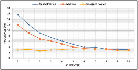
Figure 2.
The variation of the base inductance parameters as a function of the current.
2.2.1. Modelling of First Neural Network
This is conducted to develop an observer for the purpose of evaluating the performance index, and as a result, this observer is used in order to generate the feedback control. It is standard practice to use neural networks when attempting to estimate a smooth cost function on a preset data set. The expression that may be used to describe how the weights of the NN, which offer the optimum approximation solution of minimization problem for the SRM drive, work is:
where are the approximated quantities of the first NN weights that can be produced in linear system for the machine, shown as
where is the vector of the convolution operation, and it represents the number of neurons within the hidden layer. The Bellman equation can be reproduced by incorporating the Kronecker concept, which converts the weights matrix (16) into columns of bundling sequences [32].
where is the Kronecker product, and is the weights matrix derived by aggregating the entries of matrix . The left side of (17) can be defined as
By exploring and gathering sufficient data packets throughout each cycle of the normal running of the motor, including information on the modified state of the motor and the input voltage, the solution of this equation can be can be obtained. The least-squares (LS) approach can be used to improve the weights of the network. This technique is a potent optimizer that does not need any additional model identification unless an observer is required to watch the appropriate data item sets. Thus, the first NN weight’s inaccuracy error may be expressed as
Prior to applying LS strategies and to address the policy evaluation method, the total count of individual entities in the data vector should be greater than 3 samples per iteration (17). The sequential least-squares response for the NN weights is then shown as
where , , and . The dynamical parameters of the machine do not need to be inserted in order to tune the weight matrix values, and as has a complete rank, is necessary to satisfy the persistence excitation condition. This can be achieved by adding a modest amount of white noise to the input signal. It will thus be sufficient to attain the persistence excitation condition [31].
2.2.2. Modeling of Second Neural Network
This section aims to create a phase voltage signal that minimizes the approximate amount function of the first NN by approximating the ideal return voltage signal of the machine. The ideal policy to minimize the torque ripples can be expressed as follows:
Once the first value matrix has been trained until the parameters settle to their ideal values, the second online NN approximations are applied in order to achieve a result of (14) to fulfill the tracking performance and mitigate the torque ripples. The second NN formulation is described by the equation below.
where is the parameters of the activation function, where P is the quantity of neurons in the hidden layer. As a result, the actor error may be calculated as the difference between the machine’s phase voltage per phase and the control signal that minimizes the predicted performance index in the second NN, which is expressed as
The gradient descent strategy may be used to tune the variables of the second NN in real screen time. Because the network only runs a single adjusting sample, this approach is simple to encode in memory. As a result, the second NN value update may be carried out as follows:
where is a training parameter which represents the scaling factor, and is the repetition number. As demonstrated in (18), only values of the dynamical model are needed to improve the weight of the NN. The policy iteration (PI) methodology has been utilized extensively for constructing feedback controllers among the RL techniques now in use. Specifically, the linear quadratic tracker (LQT) problem is resolved using PI algorithms. It is common knowledge that resolving an LQT is necessary to solve the Algebraic Riccati equation (ARE). The PI technique starts with an acceptable control policy and iteratively alternates between policy assessment and policy improvement phases until there is no modification to the value or the policy. In contrast to the value iteration (VI) method, In contrast to the value iteration (VI) method, PI is often faster than VI as the control input converges to their optimal solution which achieve torque ripples minimization for the system model. The following Algorithm 1 shows the process which will be executed for the proposed control strategy.
| Algorithm 1: Using policy iteration approach, compute the tracking HJB problem of the model online. |
| Initialization: Launch the computation process with an allowable control policy. Perform and modify the two processes below until convergence is reached. 1st NN: 2nd NN: |
3. Simulation Results
To assess the tracking effectiveness of the suggested system, a dual-stream neural network algorithm based on reinforcement learning techniques was created and simulated for the SRM drive. The block diagram of the scheme is described in Figure 1. There are two fundamental processing stages in the control system. The first NN approximates the utility function by training the weights of NN using the least-squares (LS) method. To minimize the estimated cost function, the input signal is updated in the second NN processing block. Several data sets must be selected and estimated to train the cost function in the first NN.
To implement the proposed technique, three phases of 12/8 SRM were invested in and modeled. The nominal current of the motor was 6 A, and the resistance per phase was 2 Ω. The inductance curve fluctuated between 16 mH for maximum aligned inductance and 6 mH for minimum unaligned inductance. The rated wattage was 530 W, with a DC voltage of 100 V.
The cutoff frequency of the controller was set at 12 kHz. The developed control system’s procedure should initiate with the stabilizing control policy, according to the policy iteration approach. To show the controller’s functionality, the augmented state was set to . In the utility function, Q and R are predefined matrices of appropriate size, with values of 100 and 0.001, respectively. The discount factor used to decrease future costs was set at = 0.8. A train of rectangular shape signals with an ultimate peak value of 4A is generated by the reference signal generator. The second NN examines 10 data objects every cycle to train its value and optimize the utility function using the least-squares technique.
The parameters of the second NN approach to their ideal values after 10 epochs to minimize the torque ripples and achieve excellent performance for the motor.
The optimal first NN values reached the ideal number values which could reduce the torque ripples at
To test the suggested controller in this research, the speed of the SRM was kept constant and set at 60 RPM. The voltage provided to the motor was capped at 100 V because most of the real DC hardware’s sources are rated to this limit.
Figure 3 shows the comparison between delta modulation and the proposed method. It can be seen that RL architecture using dual NNs could efficiently minimize the torque ripples. The total torque waveform per phase is demonstrated in Figure 4. In this figure, after the weights of NNs settle to their optimal number, the controller successfully minimize the torque ripples. Figure 5 clarifies how the NN parameters settle to their ideal numbers after the NNs are fully trained.
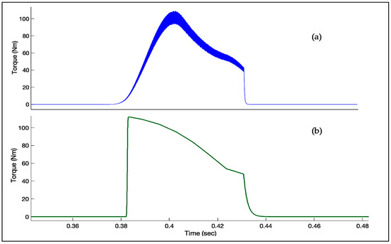
Figure 3.
The phase torque of (a) the delta modulation method; (b) the proposed method.
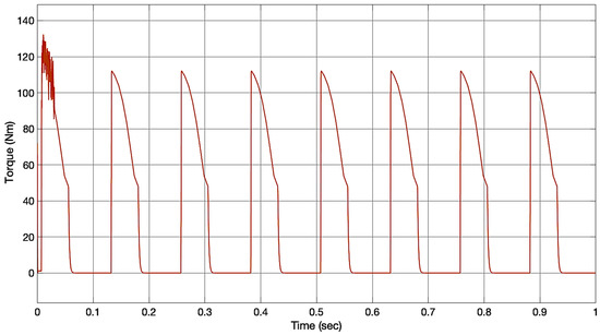
Figure 4.
The total torque per phase at constant speed.
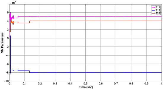
Figure 5.
The convergence of the NN parameters to their optimal solutions.
In this article, the proposed dual NN architecture parameters are only the discount factor and the learning rate. These parameters are determined based on the trial-and-error technique. For weighting the Q and R matrices, the Q/R ratio is crucial for training NNs. The linear quadratic tracker will fail to follow the reference if the weight R has a high value due to the large cost in the control input. Additionally, if R = 0 or if the Q/R ratio is extremely high, the controller will follow the reference in the first step because of the extremely high applied control input. Hence, we chose the weights to be Q = 100 and R = 0.001 as they were the best selection based on the design technique.
4. Conclusions
This paper has presented a new strategy to minimize the torque ripples using the architecture of dual-stream NNs using Reinforcement Learning for the switched reluctance motor. A new enhanced architecture for SRM has been created, which will aid in the construction of the model’s optimum tracking control. To assess the machine’s control performance, a quadratic value function for tracking and reducing the torque pulsations on the motor was constructed. To do so, dual-stream NN estimation algorithms were adopted to estimate the value function and to generate the optimal control policy. The parameters of the first NN were trained online in real time using the least-squares method until convergence. Additionally, the gradient descent logic was applied to tune the second NN. The simulation results indicated that the suggested strategy was successful at adjusting the motor’s torque and reducing its oscillations without adding additional procedures to cope with the nonlinearity of the model.
Funding
This research received no external funding.
Data Availability Statement
Not applicable.
Acknowledgments
The researchers would like to thank the Deanship of Scientific Research, Qas-sim University for funding the publication of this project.
Conflicts of Interest
The author declares no conflict of interest.
References
- Chichate, K.R.; Gore, S.R.; Zadey, A. Modelling and Simulation of Switched Reluctance Motor for Speed Control Applications. In Proceedings of the 2020 2nd International Conference on Innovative Mechanisms for Industry Applications (ICIMIA), Bangalore, India, 5–7 March 2020; pp. 637–640. [Google Scholar]
- Hao, Z.; Yu, Q.; Cao, X.; Deng, X.; Shen, X. An Improved Direct Torque Control for a Single-Winding Bearingless Switched Reluctance Motor. IEEE Trans. Energy Convers. 2020, 35, 1381–1393. [Google Scholar] [CrossRef]
- Valdivia, V.; Todd, R.; Bryan, F.J.; Barrado, A.; Lázaro, A.; Forsyth, A.J. Behavioral Modeling of a Switched Reluctance Generator for Aircraft Power Systems. IEEE Trans. Ind. Electron. 2013, 61, 2690–2699. [Google Scholar] [CrossRef]
- Gan, C.; Wu, J.; Sun, Q.; Kong, W.; Li, H.; Hu, Y. A Review on Machine Topologies and Control Techniques for Low-Noise Switched Reluctance Motors in Electric Vehicle Applications. IEEE Access 2018, 6, 31430–31443. [Google Scholar] [CrossRef]
- Sun, X.; Wan, B.; Lei, G.; Tian, X.; Guo, Y.; Zhu, J. Multiobjective and Multiphysics Design Optimization of a Switched Reluctance Motor for Electric Vehicle Applications. IEEE Trans. Energy Convers. 2021, 36, 3294–3304. [Google Scholar] [CrossRef]
- Kiyota, K.; Kakishima, T.; Chiba, A. Comparison of Test Result and Design Stage Prediction of Switched Reluctance Motor Competitive With 60-KW Rare-Earth PM Motor. IEEE Trans. Ind. Electron. 2014, 61, 5712–5721. [Google Scholar] [CrossRef]
- Bilgin, B.; Howey, B.; Callegaro, A.D.; Liang, J.; Kordic, M.; Taylor, J.; Emadi, A. Making the Case for Switched Reluctance Motors for Propulsion Applications. IEEE Trans. Veh. Technol. 2020, 69, 7172–7186. [Google Scholar] [CrossRef]
- Ghaffarpour, A.; Mirsalim, M. Split-Tooth Double-Rotor Permanent Magnet Switched Reluctance Motor. IEEE Trans. Transp. Electrif. 2022, 8, 2400–2411. [Google Scholar] [CrossRef]
- Yan, W.; Chen, H.; Liao, S.; Liu, Y.; Cheng, H. Design of a Low-Ripple Double-Modular-Stator Switched Reluctance Machine for Electric Vehicle Applications. IEEE Trans. Transp. Electrif. 2021, 7, 1349–1358. [Google Scholar] [CrossRef]
- Anwar, M.N.; Husain, I. Radial Force Calculation and Acoustic Noise Prediction in Switched Reluctance Machines. IEEE Trans. Ind. Appl. 2000, 36, 1589–1597. [Google Scholar] [CrossRef]
- Husain, T.; Sozer, Y.; Husain, I. DC-Assisted Bipolar Switched Reluctance Machine. IEEE Trans. Ind. Appl. 2017, 53, 2098–2109. [Google Scholar] [CrossRef]
- Rajendran, A.; Karthik, B. Design and Analysis of Fuzzy and PI Controllers for Switched Reluctance Motor Drive. Mater. Today Proc. 2021, 37, 1608–1612. [Google Scholar] [CrossRef]
- Abraham, R.; Ashok, S. Data-Driven Optimization of Torque Distribution Function for Torque Ripple Minimization of Switched Reluctance Motor. In Proceedings of the 2020 International Conference for Emerging Technology (INCET), Belgaum, India, 5–7 June 2020; pp. 1–6. [Google Scholar]
- Ellabban, O.; Abu-Rub, H. Torque Control Strategies for a High Performance Switched Reluctance Motor Drive System. In Proceedings of the 2013 7th IEEE GCC Conference and Exhibition (GCC), Doha, Qatar, 17–20 November 2013; pp. 257–262. [Google Scholar]
- Rahman, K.M.; Schulz, S.E. High Performance Fully Digital Switched Reluctance Motor Controller for Vehicle Propulsion. In Proceedings of the Conference Record of the 2001 IEEE Industry Applications Conference. 36th IAS Annual Meeting (Cat. No.01CH37248), Chicago, IL, USA, 30 September–4 October 2001; Volume 1, pp. 18–25. [Google Scholar]
- Gallegos-Lopez, G.; Kjaer, P.C.; Miller, T.J.E. A New Sensorless Method for Switched Reluctance Motor Drives. IEEE Trans. Ind. Appl. 1998, 34, 832–840. [Google Scholar] [CrossRef]
- Scalcon, F.P.; Fang, G.; Vieira, R.P.; Grundling, H.A.; Emadi, A. Discrete-Time Super-Twisting Sliding Mode Current Controller with Fixed Switching Frequency for Switched Reluctance Motors. IEEE Trans. Power Electron. 2022, 37, 3321–3333. [Google Scholar] [CrossRef]
- Alharkan, H.; Shamsi, P.; Saadatmand, S.; Ferdowsi, M. Q-Learning Scheduling for Tracking Current Control of Switched Reluctance Motor Drives. In Proceedings of the 2020 IEEE Power and Energy Conference at Illinois (PECI), Champaign, IL, USA, 27–28 February 2020; pp. 1–6. [Google Scholar]
- Mehta, S.; Pramod, P.; Husain, I. Analysis of Dynamic Current Control Techniques for Switched Reluctance Motor Drives for High Performance Applications. In Proceedings of the 2019 IEEE Transportation Electrification Conference and Expo (ITEC), Detroit, MI, USA, 19–21 June 2019; pp. 1–7. [Google Scholar]
- Yan, N.; Cao, X.; Deng, Z. Direct Torque Control for Switched Reluctance Motor to Obtain High Torque–Ampere Ratio. IEEE Trans. Ind. Electron. 2019, 66, 5144–5152. [Google Scholar] [CrossRef]
- Gobbi, R.; Ramar, K. Optimisation Techniques for a Hysteresis Current Controller to Minimize Torque Ripple in Switched Reluctance Motors. IET Electr. Power Appl. 2009, 3, 453–460. [Google Scholar] [CrossRef]
- Husain, I.; Ehsani, M. Torque Ripple Minimization in Switched Reluctance Motor Drives by PWM Current Control. IEEE Trans. Power Electron. 1996, 11, 83–88. [Google Scholar] [CrossRef]
- Matwankar, C.S.; Pramanick, S.; Singh, B. Position Sensorless Torque Ripple Control of Switched Reluctance Motor Drive Using B-Spline Neural Network. In Proceedings of the IECON 2021—47th Annual Conference of the IEEE Industrial Electronics Society, Toronto, ON, Canada, 13–16 October 2021; pp. 1–6. [Google Scholar]
- Schramm, D.S.; Williams, B.W.; Green, T.C. Torque Ripple Reduction of Switched Reluctance Motors by Phase Current Optimal Profiling. In Proceedings of the PESC’92 Record. 23rd Annual IEEE Power Electronics Specialists Conference, Toledo, Spain, 29 June–3 July 1992; pp. 857–860. [Google Scholar]
- Lin, Z.; Reay, D.S.; Williams, B.W.; He, X. Torque Ripple Reduction in Switched Reluctance Motor Drives Using B-Spline Neural Networks. IEEE Trans. Ind. Appl. 2006, 42, 1445–1453. [Google Scholar] [CrossRef]
- Rahman, K.M.; Gopalakrishnan, S.; Fahimi, B.; Velayutham Rajarathnam, A.; Ehsani, M. Optimized Torque Control of Switched Reluctance Motor at All Operational Regimes Using Neural Network. IEEE Trans. Ind. Appl. 2001, 37, 904–913. [Google Scholar] [CrossRef]
- Liu, D.; Lewis, F.L.; Wei, Q. Editorial Special Issue on Adaptive Dynamic Programming and Reinforcement Learning. IEEE Trans Syst. Man. Cybern. Syst. 2020, 50, 3944–3947. [Google Scholar] [CrossRef]
- Reinforcement Learning and Feedback Control: Using Natural Decision Methods to Design Optimal Adaptive Controllers. IEEE Control Syst. 2012, 32, 76–105. [CrossRef]
- Dierks, T.; Jagannathan, S. Optimal Tracking Control of Affine Nonlinear Discrete-Time Systems with Unknown Internal Dynamics. In Proceedings of the 48h IEEE Conference on Decision and Control (CDC) Held Jointly with 2009 28th Chinese Control Conference, Shanghai, China, 15–18 December 2009; pp. 6750–6755. [Google Scholar]
- Lewis, F.L.; Vrabie, D. Reinforcement Learning and Adaptive Dynamic Programming for Feedback Control. IEEE Circuits Syst. Mag. 2009, 9, 32–50. [Google Scholar] [CrossRef]
- Kiumarsi, B.; Lewis, F.L. Actor–Critic-Based Optimal Tracking for Partially Unknown Nonlinear Discrete-Time Systems. IEEE Trans. Neural Netw. Learn Syst. 2015, 26, 140–151. [Google Scholar] [CrossRef] [PubMed]
- Zhu, G.; Li, X.; Sun, R.; Yang, Y.; Zhang, P. Policy Iteration for Optimal Control of Discrete-Time Time-Varying Nonlinear Systems. IEEE/CAA J. Autom. Sin. 2023, 10, 781–791. [Google Scholar] [CrossRef]
- Yang, Y.; Modares, H.; Vamvoudakis, K.G.; He, W.; Xu, C.-Z.; Wunsch, D.C. Hamiltonian-Driven Adaptive Dynamic Programming with Approximation Errors. IEEE Trans. Cybern. 2022, 52, 13762–13773. [Google Scholar] [CrossRef]
- Ge, L.; Ralev, I.; Klein-Hessling, A.; Song, S.; De Doncker, R.W. A Simple Reluctance Calibration Strategy to Obtain the Flux-Linkage Characteristics of Switched Reluctance Machines. IEEE Trans. Power Electron. 2020, 35, 2787–2798. [Google Scholar] [CrossRef]
- Hur, J.; Kang, G.H.; Lee, J.Y.; Hong, J.P.; Lee, B.K. Design and Optimization of High Torque, Low Ripple Switched Reluctance Motor with Flux Barrier for Direct Drive. In Proceedings of the Conference Record of the 2004 IEEE Industry Applications Conference. 39th IAS Annual Meeting, Seattle, WA, USA, 3–7 October 2004; Volume 1, pp. 401–408. [Google Scholar]
Disclaimer/Publisher’s Note: The statements, opinions and data contained in all publications are solely those of the individual author(s) and contributor(s) and not of MDPI and/or the editor(s). MDPI and/or the editor(s) disclaim responsibility for any injury to people or property resulting from any ideas, methods, instructions or products referred to in the content. |
© 2023 by the author. Licensee MDPI, Basel, Switzerland. This article is an open access article distributed under the terms and conditions of the Creative Commons Attribution (CC BY) license (https://creativecommons.org/licenses/by/4.0/).