Abstract
The cogging machine is a new design of a machine with permanent magnets, which combines the advantages of a machine with transverse flux (TFM), eliminating its disadvantages. The biggest advantage of TFM machines is their high torque density, which varies with the design parameters. The developed machine retains these advantages while simplifying the construction of the stator core, which is the biggest disadvantage of TFM machines. This article presents the results of an analysis of the power density of the developed cogging machine as a function of a number of pole pairs and the basic design parameters. Analyses were carried out on the basis of the derived analytical equations, which make the generated torque depend on the construction parameters. Thanks to the derived dependencies, one can easily examine the effects of modifying the machine structure. The results presented in the article prove that the developed design of the cogging machine is competitive in relation to machines with permanent magnets existing on the market.
1. Introduction
In the new construction of electric machines designed for use in mobile drives, particular importance is attached to the power density, understood both as the ratio of the achieved power to a unit of volume and weight. Among the various types of machines with unforced cooling, constructions with permanent magnets have the highest power-density values. Among these solutions, machines with a transverse field stand out. The design of an electric machine with transverse flux (Transverse Flux Machine, TFM) was patented in 1888 [1] and almost a hundred years later it was adapted to current technical possibilities and technologies [2]. Over the past 30 years, many research papers have been devoted to TFM, e.g., [3,4,5]. There are also many review articles in the literature, the most recent of which is [6,7]. The work carried out showed its numerous positive operational properties, the most important of which is the moment obtained per volume unit, which is much higher than in classic machines. An important design advantage is the independence of the cross-section intended for the windings from the cross-section of the magnetic circuit. Despite this, it is not yet widely used or produced. The reasons for its shortcomings should be determined, the most serious of which include:
- Small use of the surface of permanent magnets;
- large leakage fluxes;
- complicated core structure;
- higher production cost.
Table 1 presents a list of parameters of individual types of machines which allows for a comparison of the performance of TFM with other types of machines. The table compares machines with similar power ratings, rotational speeds, and cooling methods.

Table 1.
Summary of features and parameters of various types of electric machines.
Due to their relatively high power and torque density, the main application area of TFM machines is electromobility. Research on this TFM application has been presented in many publications [8,9]. A special way of using this machine in vehicle drives is direct drive, mounted on the wheel [10,11]. Due to the high torque developed by the machine in the literature, a description of TFM applications in ship propulsion can also be found [12]. It was also proposed to use this machine as a direct drive wind turbine generator [13].
Machines with a transverse field are understood as constructions containing such configurations of electromagnetic circuits in which the force lines of the field mediating energy conversion remain in the plane perpendicular to the direction of motion. Figure 1 shows a general view of a motor segment with a transverse magnetic circuit [8]. Figure 2 shows a fragment of its cross section. The magnetic field lines generated by the permanent magnets on the rotor close through the inverted U-shaped stator cores. These cores encircle the coil, providing magnetic coupling. The number of U-cores is equal to half the number of pairs of magnets placed on the rotor. When the rotor rotates by the pole pitch, the direction of the field lines changes to the opposite one, due to which an alternating electromotive force can be induced in the winding. Due to the alternating flux, U cores must be made of soft magnetic materials. The system shown in Figure 1 should be considered as a segment (part) of the machine that covers its one phase. Several systems of a similar type can be combined to form a two- or multiphase machine.
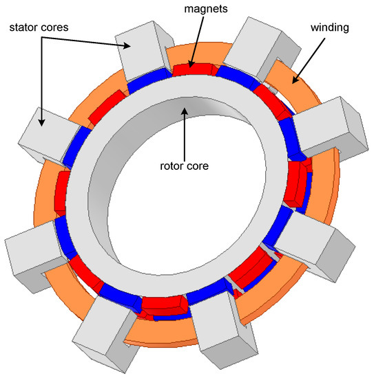
Figure 1.
General view of the TFM machine segment.
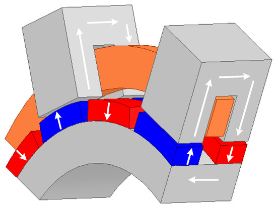
Figure 2.
A fragment of the TFM segment with the lines marked the magnetic field.
In order to improve the use of the active surface of the magnets and reduce the scattering flux, various variants of the construction described in the literature have been developed [14,15]. The modifications consisted mainly of the use of diagonal cores and the use of extensions at the ends of the cores. These solutions improved the parameters of the machines, but at the same time significantly complicated the construction of the stator cores. In practise, making them would require the use of magnetic powder compounds (MPCs), which are not widely used in the construction of electrical machines.
A New Use of the Principle of Transverse-Flux Machine Operation
The core used in classic machines with radial flux can be treated as a sequence of U cores used in the TFM machine (Figure 1) rotated 90°. With this configuration, the flux excited by the magnets no longer flows transversely but in the plane of the rotor rotation vector, hence the name flat. A machine with such a core is no longer a machine with transverse flux. However, it can retain its properties after an appropriate winding modification [16]. By rotating the U cores 90°, the flat ring of the TFM winding takes the shape of a wave winding, similar to the structure presented in [17]. To distinguish the proposed new construction, this was called the cogging motor. A general view of one segment (one phase) of the cogging machine is shown in Figure 3.
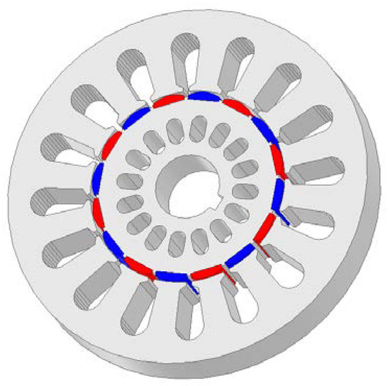
Figure 3.
General view of a cogging motor segment with a flat core.
As a result of the modification, the winding is extended by front connections, which is unfavourable from the point of view of the classic TFM design. It is also possible to wind the winding in the form of the tooth coils often used in PMAC and BLCD machines, but in this case the front windings are half as long. The segment fragment with a concentrated winding is shown in Figure 4.
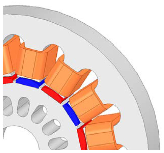
Figure 4.
Fragment of a CM segment with tooth coil winding.
The result of the proposed modification is the loss of the independent dimensioning of the magnetic and electric circuit, which is emphasised as an advantage of TFM. However, this is independence within the cross-section, not the space occupied by the machine.
Analytical tests and finite element method (FEM) tests were performed on the machine with the proposed structure, the results of which are presented in the paper [18]. They show that the average value of the torque generated by the cogging machine is approximately 25% higher than the TFM torque of the traditional design (Figure 1), and up to three times higher than the torque of the induction machine of the same size.
TFM has many valuable advantages, such as high torque and high-power density, but this is associated with its complicated segmented structure. In addition, in the original version, TFM requires a stator core with a complicated geometry. The solution to this problem is the use of the core proposed by the author (Figure 3). However, it is still a modular design, which makes it complicated to implement. These problems, which are cost-intensive, prejudge that the TFM will instead remain a structure for special applications, not used on a mass scale in industry. Currently, the most promising application area where power density is of great importance is electromobility, especially in wheel direct drives. The second area where this solution may turn out to be profitable is wind farm generators without mechanical gears.
2. Analysis of the Impact of Design Parameters on the Torque Produced by the Machine
The power density of machines excited by permanent magnets largely depends on the number of pole pairs—in [19] the kW/kg ratio was reported in the case of PMSM machines increases more than three times with the increase in the number of pole pairs.
In machines with permanent magnets of a typical structure, the number of pairs of poles is directly related to the increase in the diameter of the stator and rotor; moreover, more optimal power density parameters are obtained for structures with a larger diameter-length ratio [20]. The cogging machine is an unusual design because the machine phases form separate segments placed on a common shaft (Figure 5). The length of this structure, apart from the size of the stator and rotor cores, is also affected by the winding ends, whose axial dimension decreases with an increase in the number of pole pairs. The formulas presented in the following have been derived to capture the relationship between the method of structural division of the cross-section of the cogging machine segment and the moment generated by it. This required the introduction of several simplifications, which, for a specific structure, may result in differences between the values of the torque calculated from the formulas below and those actually generated. In particular, errors may come from the trapezoidal shape of the armature teeth assumed in the model. Magnetic tensions in the yokes were also omitted (μFe = ∞).
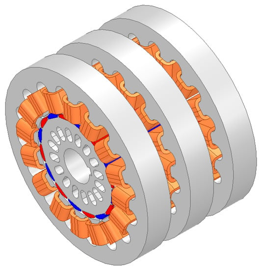
Figure 5.
General view of the three-segment (three-phase) cogging machine.
2.1. Dependence of the Torque of the Cogging Machine on the Design Parameters
In each segment of the cogging motor, the magnetic field comes from a system of 2pp magnets mounted on a cylindrical core, in the considered variant of the internal construction. The winding of one segment consists of 2pp coils connected in series, alternately wound around Zs = 2pp of the teeth of a cylindrical stator. The symbol pp denotes the number of pairs of poles of the magnets. The winding-coupled flux is the sum of the associated fluxes of the individual coils.
The associated flux of a single segment tooth coil is a periodic function of the rotor position φ:
In position φ = 0, the axis of the tooth and coil No. 1 coincides with the magnet axis of the sector with positive polarity. When the segment power supply system provides current:
then the segment produces a torque:
For ρ = 1 the torque is:
The average value of the torque for ppα = π is:
The dimensions of the segment are introduced into the torque formula via the current density in the windings. This value depends on the allowable heating of the windings and the cross-sectional area of the tooth that relates the flux to saturation-limited induction. The way of formulating the relations between the dimensions of the machine and the induction and current density depends on the location of the unwound core with magnets, which can be external or internal. In the considered construction (Figure 4), it was assumed that the wound core, also called the armature, is external.
In the armature ring, a uniform outer ring (yoke) with radii can be distinguished: external (yoke and the entire stator) Rjaz and internal Rjaw. The remaining part of the armature is also a ring made of 2pp of identical slots and teeth with an average angular width respectively βs and βt. The sum of these angles is called the slot pitch τp:
The tooth/groove ring is bounded by cylinders with a radius of Rjaw and an airgap with a radius of Rag. For the external armature, the following applies: Rag < Rjaw < Rjaz, where Rjaz is also the external radius of the machine (dimension).
If the surface of individual slots Ss and teeth St are treated as segments of the inner stator ring, the surface of the trapezoidal slot is:
Tooth surface:
The surface of the slot together with the permissible current density j determines the ampere-turns of the slot through the so-called slot utilisation factor kws. It is the relation between the cross-sectional area Ssu of the slot occupied by the wires and the cross-sectional area Ss of the slot:
The npz symbol denotes the number of wires in the slot, whereby “wire in the slot” is understood as the active side of a single turn of the coil. If each tooth is enclosed by a coil, i.e., the number of coils is equal to the number of teeth Zs = 2pp, then for identical around-tooth coils with the number of turns zcs each, npz = 2zcs must occur.
The maximum value of the current Im can now be expressed as:
The radial dimension of the teeth/slots armature ring is:
The ht value is also the height of the stator tooth. The surface area and its height can be considered as the average width of the tooth btsr:
Assuming that the coercive strength and the height of the magnet provide the maximum value of the first harmonic induction in the tooth Bt, it can be assumed (approximately) that the maximum value of the flux associated with a single-tooth coil is determined by the average thickness of the tooth.
Attention must be paid to the difference between the Bt induction value in the tooth and the induction in the gap Bm, in particular in the middle of the tooth height. It depends on many factors, and above all on the relationship between the width of the crown of the tooth and the average width of the tooth. Generally, this can be written as Bt = γ Bm. On the whole, γ > 1.
If the thickness of the armature yoke hja is taken equal to the average width of the tooth, it will be approximately equal to the length of the arc βt (Rjaw + Rag)/2:
The radius quotient of Rag/Rjaz = kpr < 1 is an important design parameter called the split ratio. This division can be called a “radial”. The “circumferential” division will be the second basic design parameter and will contain information on the division of the slot pitch into tooth and slot zone, e.g., βt/τp = kpo < 1. Of course, with that definition βs = τp(1 − kpo). By entering the division coefficients kpr and kpo in brackets (16) we get the following:
The expression for the torque will take the form:
In the case of equal 2pp around-tooth coils, npz = 2zcs, and it will be:
Formula (21) presents the average torque developed by one phase (one segment) of the cogging machine as a function of the number of pairs of poles and five design factors describing the dimensions and proportions of the machine. Using the above relationship, it is possible to analyse how the torque value changes for the cogging machine with the increase in the number of pole pairs, as well as with the change of other construction factors.
The second possible winding configuration of the cogging machine is the wave winding, which has winding ends shorter by half, which is favourable from the point of view of winding leakage flux. The general view of the wave winding is shown in Figure 6.
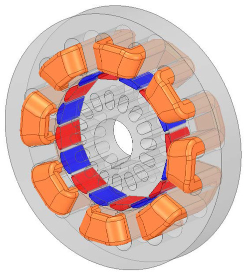
Figure 6.
General view of one cogging motor segment with the wave winding.
For wave windings, the number of coils is equal to the number of pairs of poles, with the fronts on one side of the core connecting the active sides of the coils, the fronts on the other side connecting the coils in series, one per pair of poles. The linkage flux (1) in this case will take the form:
Taking into account this change consistently in the derivations 2–21, the torque equation is obtained in the form:
Taking into account that in the wave winding zcs = npz, the final form of the formula is the same as for the loop winding (21).
2.2. Verification of the Convergence of Torque Results
Since in the presented derivation some of the parameters were included in an approximate way, it was necessary to check the discrepancies between the value of the moment determined from the formula and obtained from the calculations on the FEM 3D model. Calculations were carried out for two cases: the cogging machine with the number of pairs of poles pp = 8 and pp = 12. The configurations of both versions are shown in Figure 7 and Figure 8.
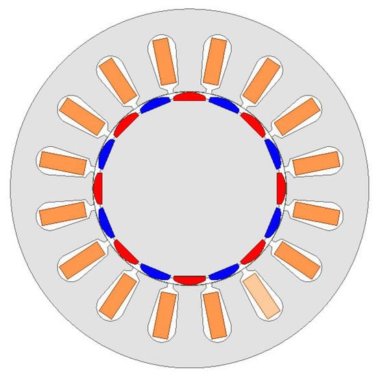
Figure 7.
Cogging motor configuration with eight pole pairs.
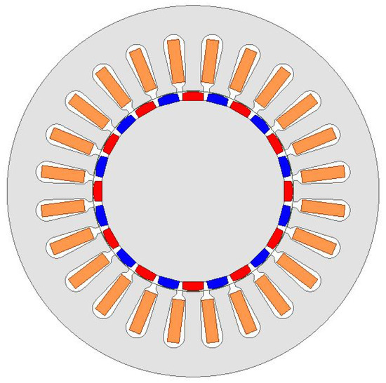
Figure 8.
Cogging motor configuration with 12 pole pairs.
The results of the FEM calculations for the configuration shown in Figure 7 and Figure 8 are shown in Figure 9. The dashed line shows the average value of the torque generated, which is 9.55 [Mm] for 8 pair poles and 11.5 [Nm] for 12 pair poles.
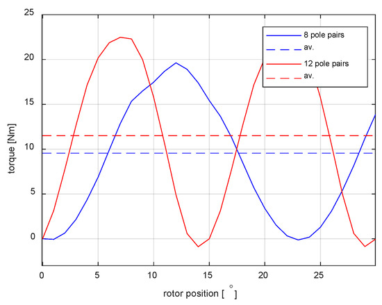
Figure 9.
Electromagnetic torque and its average value for a one segment of cogging motor with eight and 12 pole pairs.
The analytical value of the moment for both cases was calculated from Formula (21) by substituting the values and coefficients according to Figure 7 and adopted for the simulation:
Rsz = 0.95 [mm]
LFe = 0.25 [mm]
Bt = 0.9 [T]
j = 6 [A/mm2]
kws = 0.35
kpo = 0.5
kpr = 0.54
In the values adopted for the calculations, the low induction in the Bt tooth is notable. The calculations were aimed at examining the convergence of the results of analytical calculations and FEM, therefore the cross section was adopted for a non-optimised stator structure, for which βs/βt ≈ 1.
For the eight and 12 pairs of poles, the results of 11.2 [Nm] and 13.5 [Nm] were obtained, respectively. In both cases, the values calculated from Formula (21) are overestimated in relation to the FEM simulation results; the errors are 17.3% for eight pair poles and 14.8% for 12 pair poles. As mentioned above, the torque determined from Formula (21) is approximate due to the adopted simplifications (e.g., slot area); however, it should be stated that the convergence of the results is satisfactory to determine the trend of machine power density with the change in the number of pole pairs.
On the basis of the determined dependence, the curve of change of the average torque generated by one segment of the cogging machine was calculated as a function of the number of pairs of poles. All parameters adopted for the calculations are consistent with the assumptions used to verify the torque (Figure 9). The graph is shown in Figure 10.
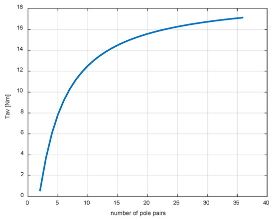
Figure 10.
The average value of the torque of one CM segment as a function of the number of pole pairs.
As can be seen in Figure 10, with the dimensions and design coefficients of the cogging machine remaining unchanged, the torque value increases with the increase in the number of pole pairs, and up to about 15 pairs of poles, these changes are significant. For larger pp values, the torque variability is much smaller. It should be added that with a fixed diameter, the adopted number of pair poles determines the dimensions of the slots, which, for technological reasons, cannot be arbitrary. Thus, for a specific machine configuration, the maximum number of pole pairs will be limited by the minimum dimensions of the slot. Assuming the output parameters for eight pairs of poles, the ratio of the torque for the three phases to the maximum phase current is Tav/Im ≈ 2. This is a higher result than that achieved in classic TFMs with an external rotor, which are generally characterised by a higher torque density [8].
3. Determination of the Dependence of the Volume and Mass of the Machine Segment on the Design Parameters
In all calculations of mass and volume, it was assumed that the rotor of the machine is a uniform structure with a density equal to the material from which the stator core was made, ignoring the air gap. However, this is an obvious simplification, taking into account that the density of electrical sheet and neodymium magnets is comparable (7.7 and 7.5 kg/dm3, respectively); it was assumed that the error resulting from this assumption will not have a large impact on the calculations of changes in the power density of the machine.
The radius of the cylinder described on the segment is Rc = Rjaz, but the length (axial dimension) lc is the sum of the lengths of the core lFe and the ends of the windings lcz:lc = lFe + 2lcz. It seems reasonable to assume that in the case of coils around single teeth, the radius of each face is equal to half of the pitch of the slot expressed in metres, on the radius Rjaw (17):
Thus, the length of the entire cylinder described on one segment is as follows.
And volume:
The coefficient kFe = lFe/Rsz is the third important design parameter adopted in the design, which demonstrates the assumed relationship between the length of the stator package and its outer radius.
In the case of a wave winding, the radius from each end depends on the angular span of the stator tooth, then Equation (24) will have the form:
Taking into account (27), the volume of the cylinder described in one segment with a wave winding will be as follows.
The dependence of the volume of one segment on the number of pair poles for the winding with toothed and wave coils, determined from the Formulas (26) and (28), is shown in Figure 11. As can be seen, the differences between the volumes are quite significant and, as expected, are more significant for configurations with fewer pole pairs. The same design factors were used for the calculations as for determining the dependence of the moment on the number of pole pairs.
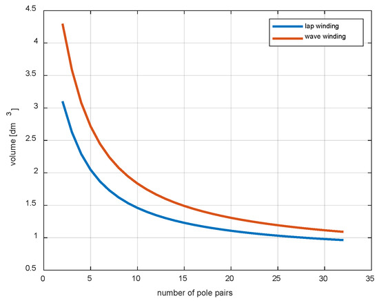
Figure 11.
Volume of one CM segment as a function of the number of pole pairs for lap and wave windings.
Having the formula describing the dependence of the radius of the winding faces, it is possible to determine the mass of the windings and the cores of the segment, similarly as before, assuming the same density of the stator and rotor material and ignoring the air gap:
wherein:
For a winding with toothed coils, the total volume of copper will be the sum of the copper in the slots and the copper of the winding ends:
So, finally, the mass of the segment:
For wave windings, the volume of the windings is as follows:
Taking into account the above, the mass for the wave winding is as follows:
The slot area Ss, in Equations (32) and (34), determined on the basis of (8) considering the introduced coefficients, is:
Comparing expressions (32) and (34), it can be seen that the mass of the segment with tooth coils is slightly smaller, the change of this value depending on the number of pair poles is shown in Figure 12. The mass of the entire segment in both cases of windings decreases with the increase in the number of pair of poles, because the number of slots in which the fill factor is smaller than one increases.
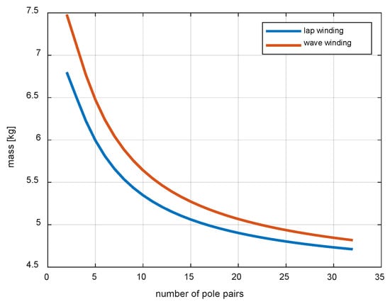
Figure 12.
Mass of one CM segment as a function of the number of pole pairs for lap and wave windings.
4. Power Density of the Cogging Machine
Using the derived torque, volume, and mass relationships as functions of the number of pair of poles and basic design factors, power density curves can be derived. When creating a machine design in terms of maximum power or torque yield per unit of mass and volume, the basic problem is to examine the dependence of these quantities on the number of pair poles. Power density is most often defined as the ratio of power to the volume or weight of the machine. The rated power of the machine is the product of the torque produced for the rated current and the rotational speed, which depends on the number of pole pairs and the frequency of the supply. For this reason, for the evaluation of the construction of a machine designed to work at a speed that varies over a wide range, it seems more reliable to replace power with the value of the torque.
For the developed structure, using the derived dependencies (23), (26), (28), (32) and (34), the curves Ts1sr/Vc Ts1sr/Mc were determined. In each case, the torque density for the lap and wave winding was calculated. Figure 13 shows the dependence of torque versus volume on the number of pairs of poles.
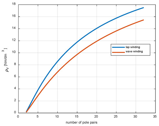
Figure 13.
The torque-to-volume ratio as a function of the number of pole pairs for lap and wave windings.
The relationship presented in Figure 13 reveals the advantage of the lap winding in relation to the wave winding. In the case of the latter solution, the ends of the windings make an arc with a larger radius, which affects the overall volume of the machine. In general, the segmental construction of the machine has an impact on enlargement of dimensions compared to classic PMSM machines, however, the increased torque yield makes it comparable to typical constructions in terms of torque density per unit volume [21]. The type of winding is less important for the torque-to-weight ratio as a function of the number of pole pairs. This is shown in Figure 14.
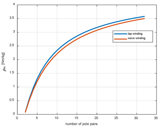
Figure 14.
The torque-to-mass ratio as a function of the number of pole pairs for lap and wave windings.
The total weight of the lap and wave windings is similar because the fronts in the first case are located on each tooth on both sides, but their volume is equal to about half the volume of the fronts of the wave winding located on every other tooth (Figure 6). The slight difference in mass is due to the different arc radius of the winding fronts in both cases. When comparing both relationships, it can be concluded that the largest changes in the torque yield from unity of mass and volume are for structures with up to about 15 pair poles. The torque density results for pole pairs greater than or equal to eight are competitive with motors designed for high-power density [10]. The second observation focusses on the advantage of lap winding over wave winding in terms of volume.
Dependence of the Torque Density on the Width of the Stator Tooth
The second relationship analysed is the change in Ts1sr/Vc and Ts1sr/Mc depending on the width of the tooth width βT. Reducing the angular width of the tooth in relation to the slot increases the surface to which the ampere turns of the armature winding are related, which causes an increase in torque with slightly changing volume and mass. Simultaneously with the reduction of the tooth width, the induction increases in it, which, after reaching the saturation level, limits the torque generated by the machine. To make the results realistic, a constraint was introduced in the calculation algorithm, which calculates the torque only for induction values below the saturation level adopted at the level of 1.7 [T]. As in the previous case, the calculations were made for two winding versions. The results of the calculations of the torque-volume ratio as a function of the span angle of the stator tooth are shown in Figure 15.
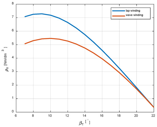
Figure 15.
The torque-to-volume ratio as a function of the stator tooth width for lap and wave windings.
The calculations show that the Ts1sr/Vc ratio reaches an extreme for a certain tooth width. For the structure adopted for calculations structure with eight pair poles, where the groove pitch τp = 22.5 [°], the extreme is reached for βT = 9 [°]. As in the previous case, much better results are achieved with the lap winding.
The same relationship was calculated for the Ts1sr/Mc coefficient. The maximum value of the coefficient also occurs for βT = 9 [°], with much smaller differences that can be observed for both types of winding (Figure 16).
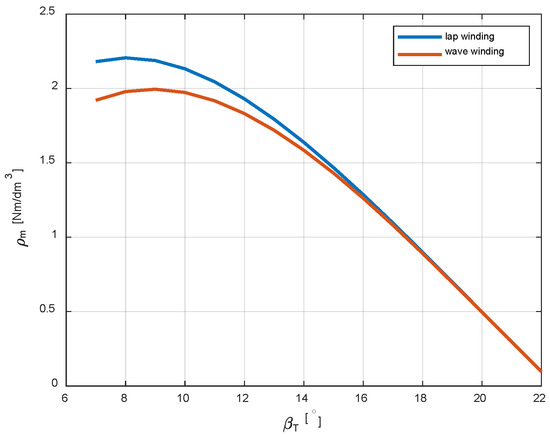
Figure 16.
The torque-to-mass ratio as a function of the stator tooth width for lap and wave windings.
5. Conclusions
This article comprehensively presented the results of research on the impact of the design parameters of the new version of the TFM on its torque density. In review articles, information on the dependence of the torque on the number of pole pairs can be found, but it concerns the classic version of TFM; however, the influence of other parameters was not considered. The derived dependencies make it possible to predict the effects of changes in the design parameters of the developed machine on its performance without using the time-consuming FEM method.
Funding
This research was funded by the AGH University of Science and Technology, research subsidy no. 16.16.120.7998.
Data Availability Statement
The data presented in this study are available on request from the corresponding author.
Conflicts of Interest
The authors declare no conflict of interest.
References
- Mordey, W.M. Electric Generator, No. 5162. U.S. Patent 437501, 30 September 1890. [Google Scholar]
- Weh, H.; May, H. Achievable Force Densities for Permanent Magnet Excited Machines in New Configurations. In Proceedings of the Internet Conference Electrical Machines (ICEM86), München, Germany, 8–10 September 1986; pp. 1107–1111. [Google Scholar]
- Sobieraj, T. Obserwator Siły Elektromotorycznej w Silniku z Magnesami Trwałymi o Strumieniu Poprzecznym. Przegląd Elektrotechniczny 2016, 1, 55–58. [Google Scholar] [CrossRef]
- Liu, C.; Wang, X.; Wang, Y.; Lei, G.; Guo, Y.; Zhu, J. Comparative Study of Rotor PM Transverse Flux Machine and Stator PM Transverse Flux Machine with SMC Cores. Electr. Eng. 2021, 104, 1153–1161. [Google Scholar] [CrossRef]
- Smoleń, A.; Gołębiowski, L.; Gołębiowski, M.; Mazur, D. Computationally Efficient Method of Co-Energy Calculation for Transverse Flux Machine Based on Poisson Equation in 2D. Energies 2019, 12, 4340. [Google Scholar] [CrossRef]
- Ballestín-Bernad, V.; Artal-Sevil, J.S.; Domínguez-Navarro, J.A. A Review of Transverse Flux Machines Topologies and Design. Energies 2021, 14, 7173. [Google Scholar] [CrossRef]
- Kaiser, B.; Parspour, N. Transverse Flux Machine—A Review. IEEE Access 2022, 10, 18395–18419. [Google Scholar] [CrossRef]
- Seibold, P.; Schuller, F.; Beez, M.; Parspour, N. Design and Measurement of a Laminated Permanent Magnet Excited Transverse Flux Machine for Electrical Vehicles. In Proceedings of the 2014 4th International Electric Drives Production Conference (EDPC), Nuremberg, Germany, 10 September–1 October 2014; pp. 1–6. [Google Scholar]
- Zhao, W.; Ahmed, A.; Husain, I.; Muljadi, E. A Novel Transverse Flux Machine for Vehicle Traction Aplications. In Proceedings of the 2015 IEEE Power & Energy Society General Meeting, Denver, CO, USA, 26–30 July 2015; pp. 1–5. [Google Scholar]
- Chasiotis, I.D.; Karnavas, Y.L. Designing High Power Density In-Wheel PMSM for Sustainable Hybrid Electric Vehicles. In Proceedings of the 2019 IEEE Workshop on Electrical Machines Design, Control and Diagnosis (WEMDCD), Athens, Greece, 22–23 April 2019; IEEE: Piscataway, NJ, USA, 2019. [Google Scholar]
- Muller, C.; Kalkmann, B.; Sontheim, J. A Highly Innovated Transversal Flux Motor Design with Integrated Inverter. In Proceedings of the 2012 2nd International Electric Drives Production Conference (EDPC); IEEE: Nuremberg, Germany, 2012; pp. 1–6. [Google Scholar]
- Dobzhanskyi, O.; Gouws, R.; Zabihi, N. High shear-stress density transverse-flux machine for large direct-driven wind turbines, and electric ship propulsion systems. In Proceedings of the The 10th International Conference on Power Electronics, Machines and Drives (PEMD 2020), Online Conference, 15–17 December 2020; Volume 2020, pp. 844–849. [Google Scholar]
- Husain, T.; Hasan, I.; Sozer, Y.; Husain, I.; Muljadi, E. Design Considerations of a Transverse Flux Machine for Direct-Drive Wind Turbine Applications. IEEE Trans. Ind. Appl. 2018, 54, 3604–3615. [Google Scholar] [CrossRef]
- Gieras, J.F. Performance Characteristics of a Transverse Flux Generator. In Proceedings of the IEEE International Conference on Electric Machines and Drives, San Antonio, TX, USA, 15 May 2005; pp. 1293–1299. [Google Scholar]
- Masmoudi, A.; Njeh, A.; Mansouri, A.; Trabelsi, H.; Elantably, A. Optimizing the Overlap Between the Stator Teeth of a Claw Pole Transverse-Flux Permanent-Magnet Machine. IEEE Trans. Magn. 2004, 40, 1573–1578. [Google Scholar] [CrossRef]
- Drabek, T.; Kapustka, P.; Lerch, T.; Skwarczyński, J. A Novel Approach to Transverse Flux Machine Construction. Energies 2021, 14, 7690. [Google Scholar] [CrossRef]
- Reinap, A.; Hagstedt, D.; Högmark, C.; Alaküla, M. Evaluation of a Semi Claw-Pole Machine with SM2C Core. In Proceedings of the 2011 IEEE International Electric Machines & Drives Conference (IEMDC), Niagara Falls, Canada, 15–18 May 2011; pp. 248–253. [Google Scholar]
- Lerch, T. Nowa Konstrukcja Maszyny o Polu Poprzecznym z Wykorzystaniem Rdzenia Płaskiego. Przegląd Elektrotechniczny 2022, 1, 191–195. [Google Scholar] [CrossRef]
- Chasiotis, I.D.; Karnavas, Y.L. A Study on Design and Optimization of High Power Density PMSM for Pod Propulsion System. In Proceedings of the 2018 XIII International Conference on Electrical Machines (ICEM), Alexandroupoli, Greece, 3–6 September 2018; IEEE: Piscataway, NJ, USA, 2018. [Google Scholar]
- Thome, R.J.; Bowles, E.; Reed, M. Integration of Electromagnetic Technologies Into Shipboard Applications. IEEE Trans. Appl. Supercond. 2006, 16, 1074–1079. [Google Scholar] [CrossRef]
- Yao, Y.; Liu, C. A Efficient Nine-Phase PM Flux-Switching Machine with High Torque Density and Low Torque Ripple. In Proceedings of the 2018 Asia-Pacific Magnetic Recording Conference (APMRC), Shanghai, China, 15–17 November 2018; pp. 1–2. [Google Scholar]
Disclaimer/Publisher’s Note: The statements, opinions and data contained in all publications are solely those of the individual author(s) and contributor(s) and not of MDPI and/or the editor(s). MDPI and/or the editor(s) disclaim responsibility for any injury to people or property resulting from any ideas, methods, instructions or products referred to in the content. |
© 2023 by the author. Licensee MDPI, Basel, Switzerland. This article is an open access article distributed under the terms and conditions of the Creative Commons Attribution (CC BY) license (https://creativecommons.org/licenses/by/4.0/).