Article

Research on the Ignition Process and Flame Stabilization of a Combination of Step and Strut: Experimental and Numerical Study

School of Aeronautics and Astronautics, Sun Yat-sen University, Shenzhen 518107, China
*
Author to whom correspondence should be addressed.
Energies 2023, 16(6), 2832; https://doi.org/10.3390/en16062832
Submission received: 14 February 2023 / Revised: 15 March 2023 / Accepted: 16 March 2023 / Published: 18 March 2023
(This article belongs to the Special Issue Thermal Fluids and Energy Systems)

Abstract

:
A combined application of step and strut was put forward to achieve reliable ignition and flame stabilization. In this work, the ignition process and temperature distribution have been tested, and a new reduction approach applied to jet fuel oxidation mechanism was developed to present a flow map via tracking C and H reaction paths, then the minor and major reactions were verified according to relative occurrence probabilities. With the half decrease of mechanism size, bias occurred and was controlled within 1.8%. This reduction method had such characteristics as universality, intuition, and quantification, due to its inherent simplification theory. This simulation of ignition process was always consistent with experimental results, which depicted kernel generation, flamelet breakup and flame propagation. Also, the influence of inlet temperature on outlet temperature and component distribution was performed, the biases of experimental and numerical results were within 5%. Chemical characteristics of Kerosene/air premixed combustible had changed and side reactions occurred to jet fuel above 900 K, which led to a converse effect on flame spreading. The side reactions aggravated the increasing coproducts of CO and CH4, which caused the decrease of volumetric heat production.

1. Introduction

With the improvement of gas turbine technology, combustion technology is constantly improving. For high-performance combustion, it needs to meet the requirements of reliable ignition and flame stabilization under various inlet conditions and a wide operating range [1]. Bluff body is frequently utilized within advanced engine afterburners and ram combustion chambers for flame stabilization in high speed airflows [2]. The step and strut are two typical model for ignition and flame stabilization, their basic performances are conducted such as ignition and extinction limits. It is also a great challenge to explore the thermal characteristics including ignition process and flame stability due to the high speed of flow and intense turbulence in the combustor [3,4,5]. Consequently, the detailed numerical simulation of their combustion continued to be out of reach [6,7,8]. To better understand the mechanism of ignition and flame stability, it is desperately needed to develop a high-precision and low-cost simulation method, which is adapted to wide range variation [9,10,11].
The most prevalent proposal to circumvent this problem is the use of a surrogate fuel. A surrogate fuel should be a mixture of a limited number of components capable of emulating some physical and/or chemical property of this target real fuel [12,13]. A surrogate consists of a mix of hydrocarbons n-decane 80% and 1,2,4-trimethybenzene 20% by weight, which is called the Aachen surrogate, and it is selected for consideration as a possible surrogate of kerosene [14]. The hydrogen to carbon (H/C) ratio for this surrogate is 2.0 this is close to the H/C ratio of 1.92 for JP-8. Additionally, the air temperature at autoignition agreed with experimental data at low values of the strain rate, which can well reproduce autoignitionand extinction characteristics of JP-8.
To better model and simulate chemical reaction process, there have been extensive number of kinetic model established for surrogate. A single detailed kinetic mechanism for the oxidation including 7920 reactions of n-decane and n-heptane has been written [15]. And several models have been built for ignition/autoignition, for example, one was for ignition involving 506 species and 3684 reactions [16]; the other was for autoignition involving 600 reactions and 67 species [17]. Pyrolysis model of n-decane was compiled and validated including 144 species and 1021 reversible reactions. Also, a large amount of models were built to predict formation as well as thermoacoustic instability [18,19]. All of these models mentioned above described kinetic of reaction well, but the elementary chemical kinetic mechanism or full chemistry was usually too detailed, computationally expensive and stiff resulting in a great challenge in combustion modelling [20,21]. A starting point for most of the reduction methods was a detailed mechanism, e.g., GRI-mech 3.0 [22], which has been studied extensively and validated experimentally serving thus as a base for different smaller mechanisms.
Several reduction methods was derived based on its merits and restrictions. Sensitivity analysis investigated the static properties of a mechanism [23,24] and species-target reduction [25,26]; this method identified species coupled together, it required an iterative procedure, and the selection of threshold values was arbitrary. Rate-Controlled Constrained Equilibrium (RCCE) [27] was combined with Computational Singular Perturbation (CSP) to identify and eliminate only the elementary reactions that were not important for any species through the use of important index [28]; CSP method [29] fully considered the time dependency of the Jacobian matrix and accurately identified the fast modes, although the refinement procedure for the time-dependent Jacobian demands heavy computation time. Consequently, for practical purposes in generating static reduced mechanisms, CPS was often used together with the constant Jacobian assumption [30]. The intrinsic low-dimensional manifold (ILDM) method that was similar in concept to CPS method was developed due to its generality and simple conception; while the ILDM was tabulated as function of a small number of variables and used in applications.
Besides the aforementioned methods, a straightforward and high-precision method of small-scale mechanism is lacking, and it is hard to calculate the thermal characteristics under complicated aerodynamic conditions, such as ignition process, outlet temperature and components distribution. In this work, a new simplification approach was developed to reduce chemical reactions of RP-3 jet fuel by tracking Carbon (C) and Hydrogen (H) reaction paths. The reaction paths with various occurrence probabilities determined minor and major reactions. This approach was generalized to adapt any elementary reactions and it illustrated quantitative and qualitative relationships among the coupled species [31]. Additionally, the accuracy and precision of mechanism have been validated over a wide range of initial gas temperatures and pressures. Also, the experimental results including ignition process, outlet temperature and components distribution were compared with numerical results over a wide range of inlet aerodynamic conditions. The detailed characteristics of ignition process were depicted even predicted for further range. And the influence of chemical kinetics and gas dynamic on outlet temperature and components was performed.

2. Methodology

2.1. Experimental Set-Up

To investigate the performance of designated combination of step and struts, premixed flow of jet-A and vitiate gas avoided the influence of two-phase. An experimental set-up was designed and presented in Figure 1, which was used to supply various inlet conditions. The inlet conditions of burner covered a large range, such as inlet temperatures (600–1200 K) and inlet velocities (50–200 m/s). This set-up involved air supply system, fuel supply system, preheating system like combustor 1 and combustor 2, and combined burner with various struts. Thermocouples and flue gas analyser were to monitor temperature and components of hot gas that was inputted into burner. The two combustors provide a basis for wide-speed incoming flow with wide-range temperature variation, and reduce the consumption of combustion resources under different working conditions through valve adjustment.
The burner involved a 100 mm vertical by 150 mm horizontal cross-section inlet and quartz windows for sidewalls, allowing full optical access to the flame shown in Figure 2. The step structure was ameliorated from conventional truncated cone and optimized with 30 mm-height step for pilot ignition. And the strut were designed with rear section widths (30 mm) and slant angles (30 deg), which was well validated with low pressure loss and good thermodynamic characteristics.

2.2. The Approach of Mechanism Reduction

This new approach was presented in Figure 3. A detailed mechanism was set as original mechanism named Mechanism_original.
Firstly, it was divided to several parts based on elements, reactions including C and H were extracted, namely, Mechanism_initial. Secondly, Mechanism_initial was simulated using CANTERA that was a suite of object-oriented software tools for problems involving chemical kinetics, thermodynamics, and/or transport processes [32]; and minor and major reactions were verified intuitively according to relative occurrence probabilities. Here reduced Mechanism_C, H was obtained via tracking C&H reaction paths. At the same time, the reduction method of Sensitivity Analysis was also conducted according to the sensitivity of intermediate species, reduced Mechanism_sensitivity with similar size was established. And then the two reduced mechanisms and Mechanism_initial were simulated using CHEMKIN to make comparison. The reduced mechanism with less bias was applied for further simplification via enlarging filtration range. Finally, with the decrease of mechanism size, the error analysis was performed to evaluate the bias brought by discounting reactions.

2.3. Simulation Method Using CFD

And this numerical simulation was conducted using Fluent 19.2, the main target was to investigate its aerodynamic performance in a reactive flow. A realizable k-e model was selected as a turbulence model. The near wall was processed using a standard wall function method. Pressure and velocity coupling was achieved using the SIMPLE (Semi-Implicit Method for Pressure Linked Equations) algorithm. Mechanism_further was used as reaction mechanism. The simulation model was simplified shown in Figure 2, the meshes were refined locally at the combination of step and strut, where the minimum was 0.5 mm and the maximum was 0.7 mm. Also, it was compared with smaller size (0.4 mm–0.6 mm) mesh to verify mesh independence. The detailed boundary conditions are shown in Table 1.

3. Results and Discussion

3.1. The Process of Mechanism Reduction

3.1.1. Selection of Original Mechanism

To describe the reduction approach distinctly, a skeletal mechanism for n-decane oxidation including 141 reactions shown in Table 1 which was developed by Chang et al. [33], had been taken as the original. And the thermodynamic data of the species refered to the detailed chemical mechanisms developed by Lawrence Livermore National Laboratory.

3.1.2. Preliminary Mechanism Reduction

Emission of NOX was not taken into consideration, a preliminarily reduced mechanism involving 128 reactions (deducting 129th–141st reactions from the original) was obtained, named Mechanism_initial (Mech_Ini). Numerical simulations using Mechanism_initial were conducted with stoichiometric mixture of n-decane/air. The diagram of chemical transformations tracking C&H according to this initial mechanism was shown in Figure 4 and Figure 5. The weight of lines and the value beside the lines represented the relative occurrence probabilities of reactions. It was quantitative and qualitative to demonstrate the coupling relationship of species. C&H reaction paths were straightforward to identify and then eliminate the unimportant elementary reactions that contribute negligibly to the production of every species. It well avoided the problem of discounting unimportant species that was possibly kept in a group strongly couple to it. This approach reproduced reaction diagram that demonstrated main and intermediate reactions successfully. The major paths of consuming fuel were thermal decomposition leading to H abstraction. The following notation was used here and in what follows: RH = CnH2n+2, R = CnH2n+1, Q = CnH2n. Once reacting, C10H21 was the indispensable and coupled strongly with several long-chain hydrocarbons, which determined 1st–7th reactions cannot be neglected. It included:
(1)
Oxidation of alkane and alkyl radical: RH + O2 = R + HO2, R + O2 = QOO;
(2)
H-atom abstraction from alkane: RH + H = R + H2, RH + OH = R + H2O;
(3)
Isomerization of the alkyl radical: (ROO)1 = (ROO)2.
The products of the decomposition of alkyls higher than C3 also underwent thermal decompositions fast and formed C3- and C2- species, with ethylene (C2H4) and propene (C3H6) being the important stable ones. C2H5 (or C2H4) and C3H6 were the only two resultants from C10H21, therefore, 8th–12th reactions were remained. Here summarized, 1st–12th were decomposition process from long chain structure to short chain structure, which constituted main reactions. The main reduction was performed to C2-C3 skeletal mechanism and H2/CO/C1 detailed mechanism. The species occurred in Figure 4 and Figure 5 were coupled strongly and connected tightly.
The reactions related to these species were with various importance, it was basic reference to eliminate some reactions which occurred with probability smaller than 0.02 were removed firstly. And some reactions with the species not existing in the reaction diagram were discounted, such as species CH2CO. Thus, a more simplified reaction mechanism was put forward named Mechanism_C, H (Mech_CH) including 87 reactions (deducting 41 reactions: 15th, 23rd, 33rd–37th, 39th, 50th, 53rd–61st, 68th, 71st, 72nd, 86th, 92nd–100th, 104th, 105th, 107th, 110th,111st, 119th, 120th, 122nd, 123rd, 125th).
For comparison, the initial mechanism was also simplified using the reduction method of Sensitivity analysis. Sensitivity analysis of intermediate species, such as C2H4, C2H5, and C3H6, was conducted via CHEMKIN; reactions which satisfied the inequation blow were removed:
(Reaction − Sensitivity)i/(Reaction − Sensitivity)max < 0.01
where (Reaction-Sensitivity)i was sensitivity of each reaction, and (Reaction-Sensitivity)max was the biggest value of all. Then reduced mechanism by sensitivity analysis was established, named Mechanism_sensitivity (Mech_Sen, deducting 10th, 12nd, 20th, 24th, 27th, 29th, 30th, 33rd, 34th, 37th–39th, 44th, 46th–48th, 54th, 57th–65th, 69th–71st, 74th–76th, 88th, 90th, 91st, 98th, 99th, 107th–110th, 113rd–116th, 120th, 121st, 123rd), whose size (including 84 reactions) was similar to Mechanism_C, H.

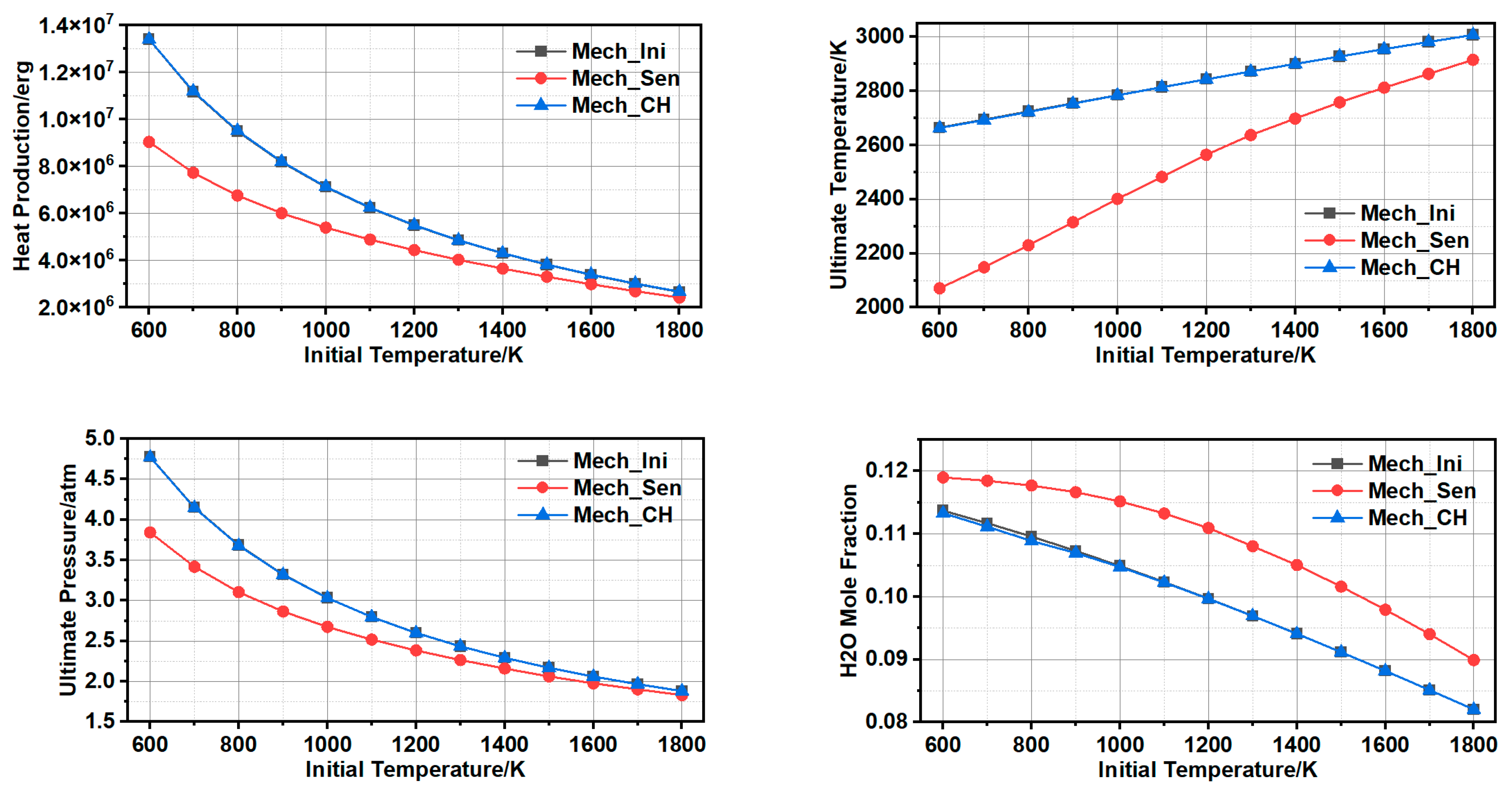
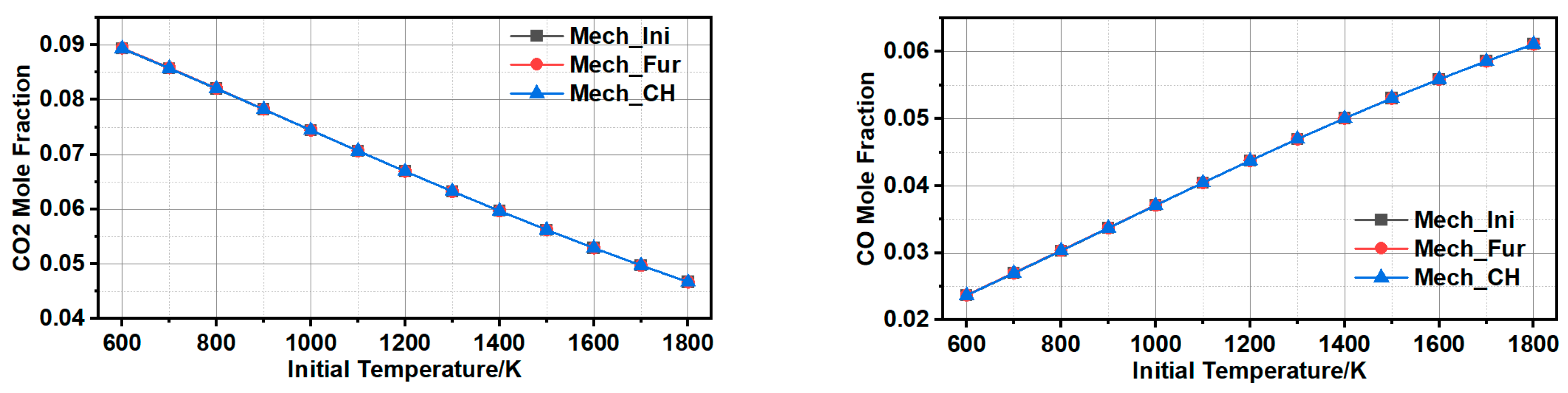
3.1.3. Comparison and Validation

The two reduced mechanisms (Mechanism_C, H, Mechanism_sensitivity) and initial one (Mechanism_initial) were applied to simulate closed, homogenous and constrain-volume reaction via CHEMKIN. The evaluation indexes were critical factors to assess combustion efficiency and performance, such as heat production, temperature ratio, pressure ratio, H2O, CO2, and CO. Moreover, the objective was also to validate the reduction method by tracking C&H reaction paths.
As shown in Figure 6, the results of evaluation indexes, such as heat production, temperature ratio, pressure ratio, and H2O, CO, and CO2, illustrated the similar trend; when temperature increased, the biases decreased. However, the simulation results of CO2 and CO using Mechanism_sensitivity went absolutely against using Mechanism_initial and Mechanism_C, H.
As was shown in Figure 4, the species of HCO was on the key position, especially for the production of CO and CO2. Reactions from 62th to 75th were related tightly to species of CO/HCO. The simplification of Sensitivity Analysis method removed this part then led to misfit the initial mechanism. While results of Mechanism_initial and Mechanism_C, H went with same trend and appeared little difference as to each evolution index, this demonstrated that the approach via tracking C&H reaction paths was a validated reduction approach.

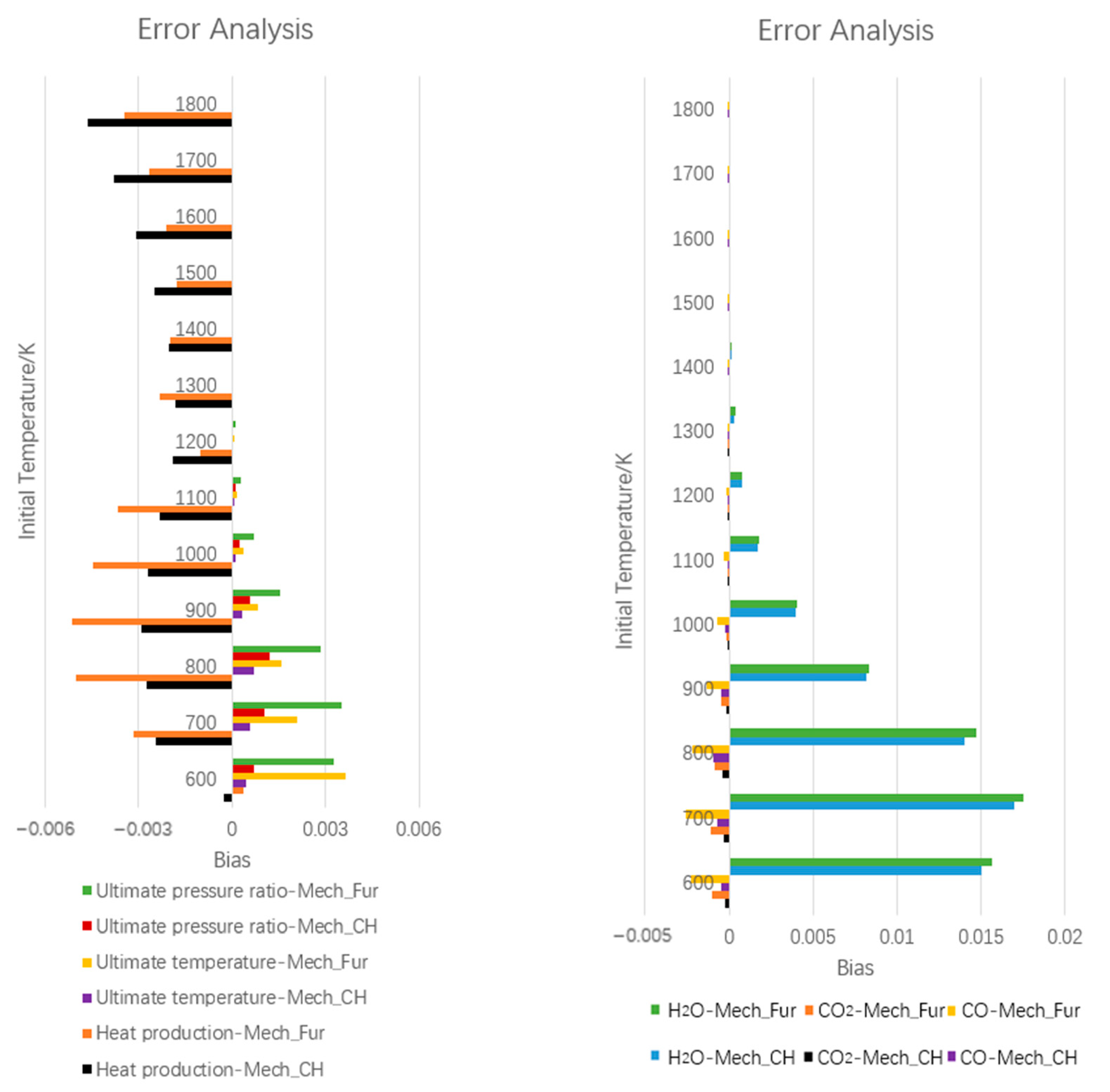
3.1.4. Further Simplification of Mechanism and Error Analysis

Further simplification of mechanism (Mechanism_further) was performed through enlarging the discounting limit from 0.2 to 0.3, and 9 reactions were discounted (deducting 51st, 52nd, 85th, 87th, 113rd, 116th–118th, 128th). Mechanism_further (Mech_Fur) involving 78 reactions was also applied to simulate closed, homogenous and constrain-volume reaction with stoichiometric mixture of n-decane/air via CHEMKIN. The simulation results of evaluation indexes, such as heat production, temperature ratio, pressure ratio, H2O, CO2, and CO, were shown in Figure 7.
Each evaluation index of Mechanism_further went the same trend with Mechanism_initial and Mechanism_C, H, which verified the method of further simplification method was available. Due to discounted elementary reactions, biases occurred, and it inevitably did. Error analysis would be imperative to measure whether further simplification need to be continued. As to the biases of Mechanism_C, H and Mechanism_further, the results of Mechanism_initial application was as standard.
Error   analysis ( Mech _ CH ) = (   Index ( Mech Ini )   Index ( Mech _ CH ) ) Index ( Mech Ini )  
Error   analysis ( Mech _ Fur ) = ( Index ( Mech _ Ini )   Index ( Mech _ Fur )   ) Index ( Mech _ Ini )
As was presented in Figure 8, absolute maximum biases of heat production, temperature ratio and pressure ratio, were less than 0.6%; the maximum bias of resultants, such as H2O, reached 1.8%. In addition, Positive or negative number presented relative size. Ultimate pressure and temperature, as well as production of H2O of the two reduced mechanisms were greater than of initial mechanism. The main way to produce heat was transformation between CO and CO2; the production of CO and CO2 calculated by the two reduced mechanisms was smaller than by original mechanism, hence, heat production was little decreasing with the reduced reactions.
Except for heat production, the others kept in the same trend: biases declined with the growing temperature. Here explained, the second bias growth of heat production with increasing temperature was due to the occurrence of side reactions. Overall, the biases of the reduced mechanisms were limited to a reasonable and acceptable range. A reduced mechanism with high precision and fidelity was developed using reduction approach of tracking C&H reaction paths. According to the acceptable bias in practical engineering, this approach was performed to reduce detailed mechanism to a smaller size. The former detailed mechanisms were with hundreds or thousands of redundant elementary reactions and species. While, the smaller size of reduced mechanism was applied to engineering practice to predict the reaction resultants more concise, especially for the numerical simulation with huge computational cost. For example, calculation fluid dynamics (CFD) was commonly used for simulate combustion process, the supersized mechanism was an additional burden that extended beyond the capacity of calculation in most cases.

3.2. Experimental and Numerical Ignition Process

3.2.1. The Validation of Simulation Method

The development process of ignition was conducted using CFD and high speed camera including kernel generation, growth and propagation. Figure 9 showed the ignition process within 6 ms and the self-luminous flame structure was photographed in the observation window with a spatial resolution slightly lower than 5 million pixels and a shooting frame rate of 1000 frames per second. It presented the consistence of simulation and experimental results, at the same time, it was also a good verification of simulation accuracy. The results clearly revealed the detailed development processes. As shown in Figure 8, in the first millisecond, the spark discharged, the flame kernel generated and it surrounded the igniter. Due to the aerodynamic conditions, flame kernel was bent out of shape. In the second millisecond, flame kernel was in an irregular shape attached on the step where the velocity zone was low. It was conductive to flame stabilization and propagation. In the third and fourth milliseconds, flame grew rapidly and ‘climbed’ along the back face of strut. It also included the breakup of flame surface, then the break-up flamelet propagated to further zone and ignited the unburned mixed gas. In the fifth and sixth milliseconds, flame was fully developed and filled the whole burner. As shown, the motion trail of flame was regular and it was related to aerodynamic conditions.
To better understand the development process of ignition, flow pattern and flame structure were presented in Figure 10, the influence of aerodynamics was complicated. Firstly, once the flame kernel generated, its windward surface was deformed by the inlet flow. Then distortion, folding and curling occurred to aggravate the heat release rate, at the same time, severe deformation would cause energy dissipation even blow-out. Secondly, there was a recirculation zone behind the radial stabilizer, and it was irregularly distributed. As shown, heat and mass transfer happened in the recirculation zone, which provided momentum transport for the radial flame propagation. Thirdly, little recirculation zones of pilot zone were different from main recirculation zone but connected with it. Based on the little recirculation zones, heat and mass transfer occurred more easily, which was conducted to flame propagation and stabilization in pilot zone.

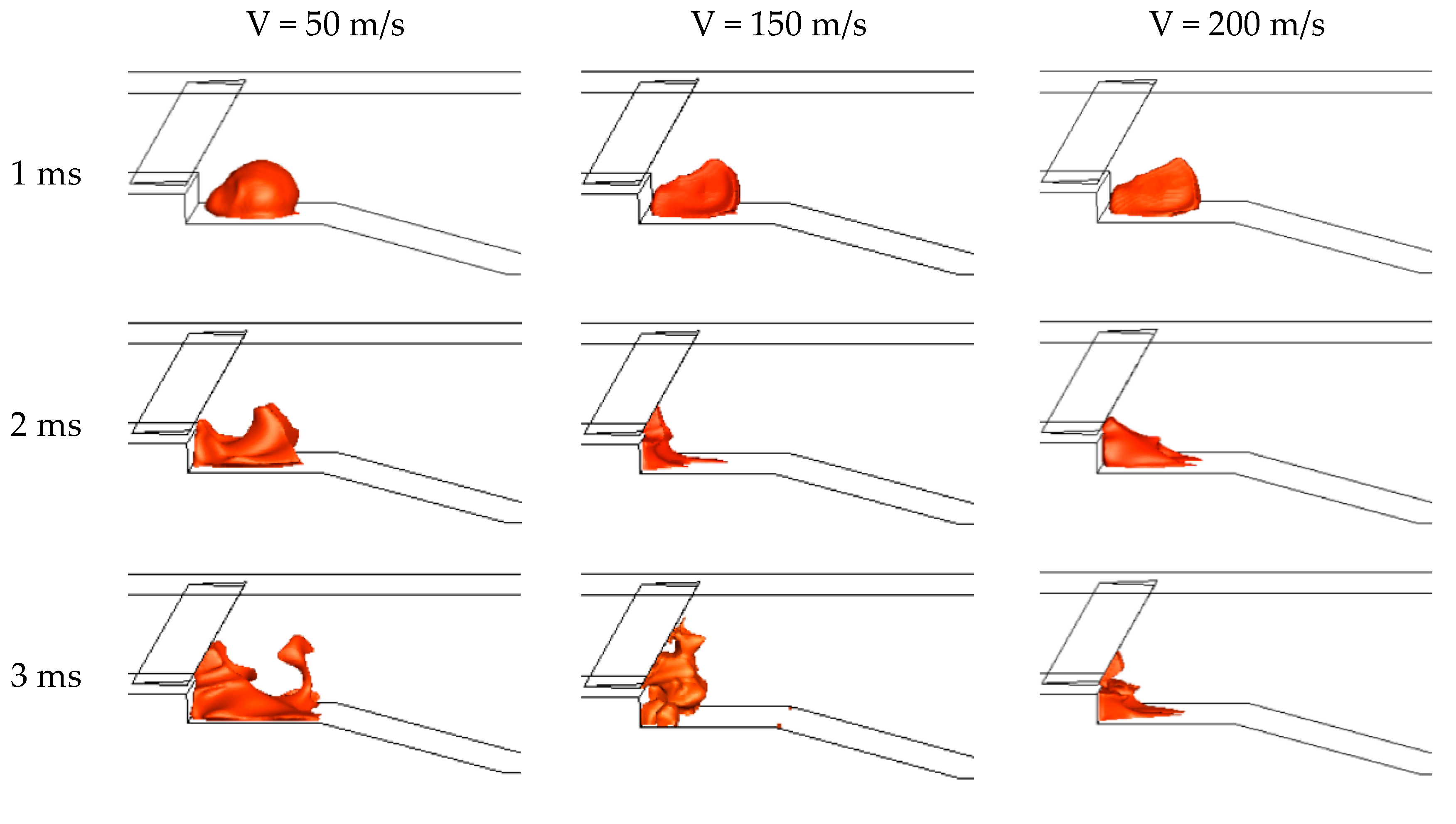
3.2.2. The Predictions of Ignition Process

Figure 11 showed the influence of velocity (50 m/s, 100 m/s and 150 m/s) on ignition process using numerical simulation. As shown, firstly, once the spark discharged and flame kernel generated, the size of flame kernel was decreasing with the growth of velocity, and the deformation of flame surface was increasing. It was due to the smaller flux at lower velocity, the one-time discharged spark energy could ignited more combustible gas and generated bigger flame kernel. Secondly, the time of complete flame propagation was longer with the growth of velocity. It was related to propagation path, the energy of flame kernel at 50 m/s enough to meet the requirements of igniting surroundings, making flame kernel to propagate along multiple directions and fill the complete burner as quickly as possible; however, flame kernels at 150 m/s and 200 m/s generated and were in irregular shapes attached on the step where the velocity zone was low, then flame kernel grew rapidly and ‘climbed’ along the back face of strut to realize filling the whole burner. Thirdly, in the propagation process, the flame might get broken up and the broken flame fell off to ignite further unburned gas, and the separated burning zone reconnected to complete flame propagation.

3.3. Outlet Temperature Distribution

Figure 12 shows the outlet temperature distribution of the combination of step and strut, the simulation results are calculated using the numerical method introduced in Section 2.3, and the experimental results of outlet temperature are tested with B type thermocouples, including the inlet temperatures of 750 K, 900 K and 1050 K, respectively. As shown, the outlet temperature distributions of simulations were higher than it of experiments, the bias of simulations and experiments were within 5%. It illustrated that the novel numerical method worked effectively and achieved high precision. Also, the growth rate of outlet temperature was decreasing with the increase of inlet temperature. Chemical characteristics of Kerosene/air premixed combustible had changed at high temperature. A mixture of n-decane and 1,2,4-trimethybenzene (8:2, by weight), called the Aachen surrogate, was selected for consideration as a possible surrogate of kerosene. Side reactions occurred to n-decane above 900 K, which led to a converse effect on flame spreading.
This result shows a unified phenomenon that the outlet temperature of central region was lower than the other regions. Once the recirculation zone ignited, the flame spread along the expansion structure, and the volumetric enthalpy of combustion is diluted, which causes local temperature to decrease. And it shows that the high-temperature region is concentrated in the toroidal surface, it proves that the rationality of combined design.

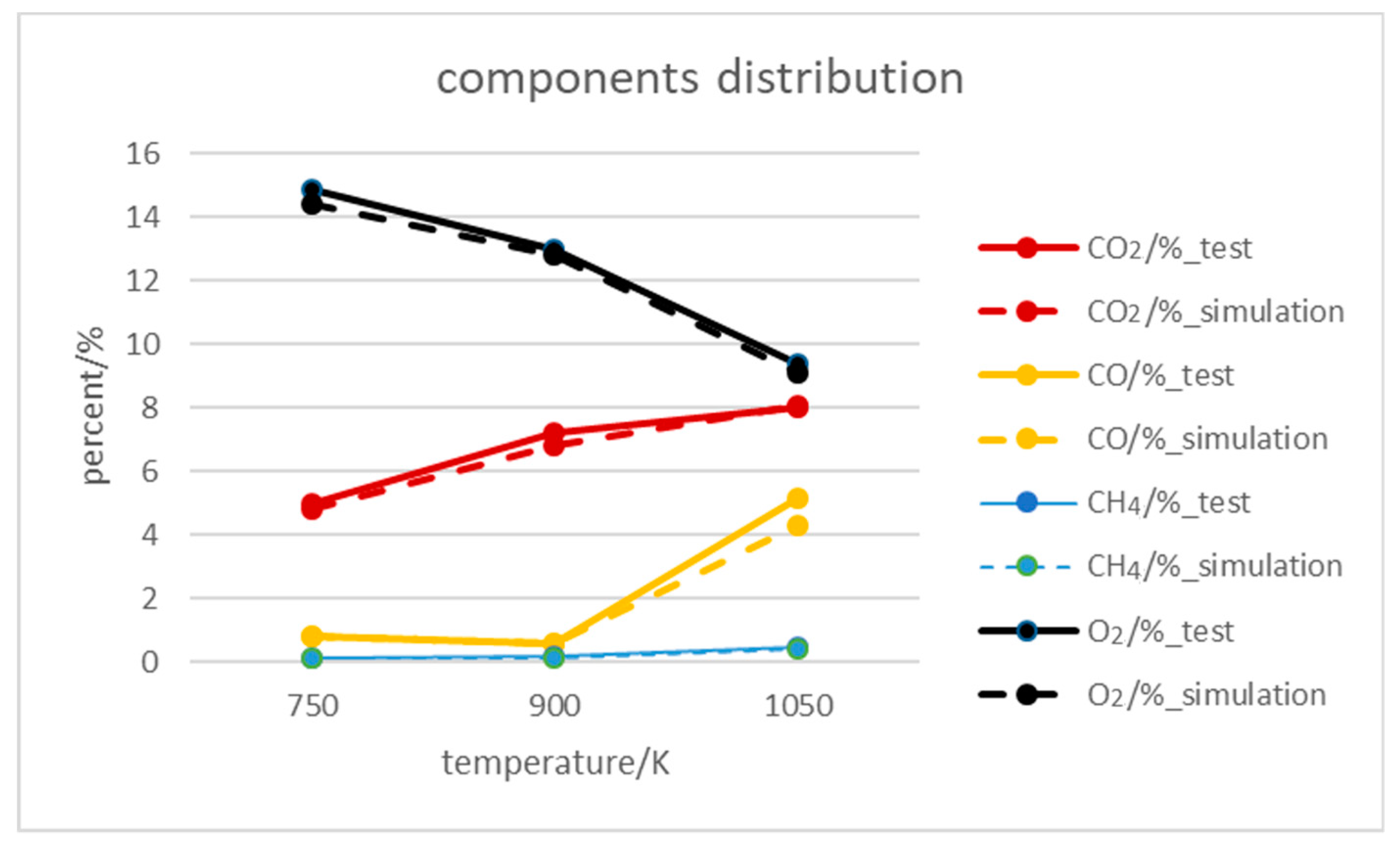
3.4. Outlet Components Distribution

Figure 13 shows the outlet components distribution of the combination of step and strut, the simulation results are also calculated using the numerical method introduced in Section 2.3, and the experimental results are tested with flue gas analyser, including the inlet temperatures of CO2, CO, CH4 and O2, respectively. The bias of simulations and experiments were within 3%. As shown, the component of O2 was decreasing with the increase of inlet temperature, the reactions occurred in oxygen-lean condition, especially in inlet temperature the 1050 K. The main way to produce heat was transformation between CO and CO2; the production of CO and CO2 existed a turning point at 900 K in the growth of inlet temperature. Extra-high temperature oxidation aggravated the side reactions, the formation of CO2 was impaired and the coproducts of CO and CH4 were promoted. This trend proved that the growth rate of outlet temperature was decreasing with the increase of inlet temperature.

4. Conclusions

In this work, modelling, simulations and experiments were performed including mechanism reduction, ignition process and flame stabilization. The following conclusions were drawn:
(1)
A simplified mechanism was developed and verified using a reduction approach according to tracking C&H reaction paths, especially by tracking key elementary reactions more clearly such as correlate heat release. Compared with the sensitivity analysis method, the element tracing method based on probability density distribution proposed in this paper has stronger adaptability and higher accuracy. Mathematical equilibrium model and calculation were developed based on Gibbs principle of minimum free energy. And this simplified mechanism with half the size, but got similar accuracy and fidelity with its error controlled within 1.8%.
(2)
This simplified mechanism was well adapted to ignition simulation and prediction under complicated aerodynamic conditions, and its simulation was always consistent with experimental results. Base on the validated simulation method, flame details including kernel generation, flamelet breakup and flame propagation, were depicted and analysed; and the ignition process was predicted under the wider variation of velocity. Also, it provides possibilities for predicting ignition performance prediction beyond the designed boundary conditon.
(3)
The influence of inlet temperature on outlet temperature and component distribution was performed, the bias of experimental and numerical results was within 5%. The higher temperature accelerated side reactions, which caused the increasing coproducts of CO and CH4, also led to the decrease of volumetric heat production.

Author Contributions

Conceptualization, S.Z.; Methodology, S.Z. and H.X.; Software, S.Z., H.X. and Y.L.; Writing—original draft, S.Z. and Y.L. All authors have read and agreed to the published version of the manuscript.

Funding

This research was funded by [Science Center for Gas Turbine Project] grant number [P2022-B-Ⅱ-018-001].

Data Availability Statement

The data presented in this study are available on request from the corresponding author. The data are not publicly available due to privacy restrictions.

Conflicts of Interest

The authors declare no conflict of interest.

References

  1. De Giorgi, M.G.; Sciolti, A.; Campilongo, S.; Ficarella, A. Image processing for the characterization of flame stability in a non-premixed liquid fuel burner near lean blowout. Aerosp. Sci. Technol. 2016, 49, 41–51. [Google Scholar] [CrossRef]
  2. Hernández, S.; Menga, E.; Moledo, S.; Romera, L.; Baldomir, A.; López, C.; Montoya, M.C. Optimization approach for identification of dynamic parameters of localized joints of aircraft assembled structures. Aerosp. Sci. Technol. 2017, 69, 538–549. [Google Scholar] [CrossRef]
  3. Zhang, J.; Zhou, X.; Han, H.; Huang, S.; Li, Z.; Zhong, H. Experiment on the influence of flow number of the pilot-stage centrifugal atomizer on ignition performance of internally staged combustor. Fuel 2022, 318, 123329. [Google Scholar] [CrossRef]
  4. Zhang, H.-L.; He, L.-M.; Chen, G.-C.; Qi, W.-T.; Yu, J.-L. Experimental study on ignition characteristics of kerosene–air mixtures in V-shaped burner with DC plasma jet igniter. Aerosp. Sci. Technol. 2018, 74, 56–62. [Google Scholar] [CrossRef]
  5. Huang, Y.; He, X.; Zhang, H.; Wei, J.; Sng, D.W.M. Spark ignition and stability limits of spray kerosene flames under subatmospheric pressure conditions. Aerosp. Sci. Technol. 2021, 114, 106734. [Google Scholar] [CrossRef]
  6. Vozka, P.; Kilaz, G. A review of aviation turbine fuel chemical composition-property relations. Fuel 2020, 268, 117391. [Google Scholar] [CrossRef]
  7. Miao, J.; Fan, Y.; Wu, W.; Zhao, S. Influence of air-entraining intensity on the afterburner ignition, flame-holding and combustion characteristics. Aerosp. Sci. Technol. 2020, 106, 106063. [Google Scholar] [CrossRef]
  8. Zhao, S.; Fan, Y. Experimental and numerical study on fuel distribution and flame expansion of the enhanced flame holding devices. Energy 2020, 203, 117850. [Google Scholar]
  9. Zettervall, N.; Fureby, C.; Nilsson, E. A reduced chemical kinetic reaction mechanism for kerosene-air combustion. Fuel 2020, 269, 117446. [Google Scholar] [CrossRef]
  10. Liu, F.; Zhou, L.; Hua, J.; Liu, C.; Wei, H. Effects of pre-chamber jet ignition on knock and combustion characteristics in a spark ignition engine fueled with kerosene. Fuel 2021, 293, 120278. [Google Scholar] [CrossRef]
  11. Santana, E.R.; Weigand, B. Effect of the reaction mechanism on the numerical prediction of the performance of a scramjet combustor at cruise flight 8 Mach number. Aerosp. Sci. Technol. 2021, 112, 106595. [Google Scholar] [CrossRef]
  12. Dooley, S.; Won, S.H.; Heyne, J.; Farouk, T.I.; Ju, Y.; Dryer, F.L.; Kumar, K.; Hui, X.; Sung, C.-J.; Wang, H.; et al. The experimental evaluation of a methodology for surrogate fuel formulation to emulate gas phase combustion kinetic phenomena. Combust. Flame 2012, 159, 1444–1466. [Google Scholar] [CrossRef]
  13. Luo, Z.; Plomer, M.; Lu, T.; Som, S.; Longman, D.E. A reduced mechanism for biodiesel surrogates with low temperature chemistry for compression ignition engine applications. Combust. Theory Model. 2012, 16, 369–385. [Google Scholar] [CrossRef]
  14. Honnet, S.; Seshadri, K.; Niemann, U.; Peters, N. A surrogate fuel for kerosene. Proc. Combust. Inst. 2009, 32, 485–492. [Google Scholar] [CrossRef]
  15. Battin-Leclerc, F.; Fournet, R.; Glaude, P.; Judenherc, B.; Warth, V.; Côme, G.; Scacchi, G. Modeling of the gas-phase oxidation of n-decane from 550 to 1600 K. Proc. Combust. Inst. 2000, 28, 1597–1605. [Google Scholar] [CrossRef]
  16. Moréac, G.; Blurock, E.S.; Mauss, F. Automatic generation of a detailed mechanism for the oxidation of n-decane. Combust. Sci. Technol. 2006, 178, 2025–2038. [Google Scholar] [CrossRef]
  17. Bikas, G.; Peters, N. Kinetic modelling of n-decane combustion and autoignition: Modeling combustion of n-decanem. Combust. Flame 2001, 126, 1456–1475. [Google Scholar] [CrossRef]
  18. Ryu, J.I.; Kim, K.; Min, K.; Scarcelli, R.; Som, S.; Kim, K.S.; Temme, J.E.; Kweon, C.B.M.; Lee, T. Data-driven chemical kinetic reaction mechanism for F-24 jet fuel ignition—ScienceDirect. Fuel 2020, 290, 119508. [Google Scholar] [CrossRef]
  19. Dillstrom, T.; Violi, A. The effect of reaction mechanisms on the formation of soot precursors in flames. Combust. Theory Model. 2017, 21, 23–34. [Google Scholar] [CrossRef]
  20. Tang, Y.; Hassanaly, M.; Raman, V.; Sforzo, B.; Seitzman, J. Probabilistic modeling of forced ignition of alternative jet fuels. Proc. Combust. Inst. 2020, 38, 2589–2596. [Google Scholar] [CrossRef]
  21. Sun, W.; Chen, Z.; Gou, X.; Ju, Y. A path flux analysis method for the reduction of detailed chemical kinetic mechanisms. Combust. Flame 2010, 157, 1298–1307. [Google Scholar] [CrossRef]
  22. Smith, G.P.; Golden, D.M.; Frenklach, M.; Moriarty, N.W.; Eiteneer, B.; Goldenberg, M.; Bowman, C.T.; Hanson, R.K.; Song, S.; Gardiner, W.C., Jr.; et al. GRI Mechanism. Available online: http://www.me.Berkeley.edu./gri-mech/ (accessed on 27 July 2010).
  23. Nadiri, S.; Agarwal, S.; He, X.; Kühne, U.; Fernandes, R.; Shu, B. Development of the chemical kinetic mechanism and modeling study on the ignition delay of liquefied natural gas (LNG) at intermediate to high temperatures and high pressures. Fuel 2021, 302, 121137. [Google Scholar] [CrossRef]
  24. Shu, J.; Fu, J.; Liu, J.; Ma, Y.; Wang, S.; Deng, B.; Zeng, D. Effects of injector spray angle on combustion and emissions characteristics of a natural gas (ng)-diesel dual fuel engine based on cfd coupled with reduced chemical kinetic model. Appl. Energy 2019, 233–234, 182–195. [Google Scholar] [CrossRef]
  25. Li, R.; Li, S.; Wang, F.; Li, X. Sensitivity analysis based on intersection approach for mechanism reduction of cyclohexane. Combust. Flame 2016, 166, 55–65. [Google Scholar] [CrossRef]
  26. Stagni, A.; Frassoldati, A.; Cuoci, A.; Faravelli, T.; Ranzi, E. Skeletal mechanism reduction through species-targeted sensitivity analysis. Combust. Flame 2016, 163, 382–393. [Google Scholar] [CrossRef]
  27. Koniavitis, P.; Rigopoulos, S.; Jones, W.P. Reduction of a detailed chemical mechanism for a kerosene surrogate via RCCE-CSP. Combust. Flame 2018, 194, 85–106. [Google Scholar] [CrossRef] [Green Version]
  28. Lu, T.; Ju, Y.; Law, C.K. Complex CSP for chemistry reduction and analysis. Combust. Flame 2001, 126, 1445–1455. [Google Scholar] [CrossRef]
  29. Correa, C.; Niemann, H.; Schramm, B.; Warnatz, J. Reaction mechanism reduction for higher hydrocarbons by the ILDM method. Proc. Combust. Inst. 2000, 28, 1607–1614. [Google Scholar] [CrossRef]
  30. Lu, T.; Law, C.K. A directed relation graph method for mechanism reduction. Proc. Combust. Inst. 2005, 30, 1333–1341. [Google Scholar] [CrossRef]
  31. Zhao, S.; Fan, Y. Analysis of flow resistance and combustion characteristics in the combined application of step and strut. Aerosp. Sci. Technol. 2020, 98, 105676. [Google Scholar]
  32. Le Dortz, R.; Bellenoue, M.; Bonneau, L.; Mazanchenko, E.; Sotton, J.; Strozzi, C. Laminar Burning Velocities and Markstein Lengths of Jet Fuel Surrogate/Air Mixtures in a Spherical Chamber. In Proceedings of the 8th European Combustion Meeting, Dubrovnik, Croatia, 18–21 April 2017. [Google Scholar]
  33. Chang, Y.; Jia, M.; Liu, Y.; Li, Y.; Xie, M. Development of a new skeletal mechanism for n-decane oxidation under engine-relevant conditions based on a decoupling methodology. Combust. Flame 2013, 160, 1315–1332. [Google Scholar] [CrossRef]
Figure 1. Structure of experimental system [31].
Energies 16 02832 g001
Figure 2. Burner of physical dimension [31]. 1. inlet cross section; 2. Injectors; 3. Thermocouples; 4. Stabilizer; 5. observation window; 6. spark-plug; 7. outlet cross section.
Energies 16 02832 g002
Figure 3. The flow chart of the new developed approach.
Energies 16 02832 g003
Figure 4. Flow map of C reaction path.
Energies 16 02832 g004
Figure 5. Flow map of H reaction path.
Energies 16 02832 g005
Figure 6. Comparison of the results via Mech_Ini, Mech_Sen and Mech_CH.
Energies 16 02832 g006aEnergies 16 02832 g006b
Figure 7. Comparison of the results via Mech_Ini, Mech_Fur and Mech_CH.
Energies 16 02832 g007aEnergies 16 02832 g007b
Figure 8. Error analysis of Mech_Fur and Mech_CH based on Mech_Ini.
Energies 16 02832 g008
Figure 9. Ignition process using CFD and high speed camera.
Energies 16 02832 g009
Figure 10. The influence mechanism of flow and ignition.
Energies 16 02832 g010
Figure 11. The influence of velocity on ignition process.
Energies 16 02832 g011aEnergies 16 02832 g011b
Figure 12. The influence of inlet temperature on the change outlet temperature.
Energies 16 02832 g012
Figure 13. The influence of inlet temperature on the gas component.
Energies 16 02832 g013
Table 1. Boundary conditions.
Boundary ConditionsBoundary LocationParameters
Velocity inletInletV = 50, 100, 150, 200 m/s; T = 320 K
OutflowOutlet
WallSolid wall and liquid boundaryStationary wall; no slip; no heat flux
Disclaimer/Publisher’s Note: The statements, opinions and data contained in all publications are solely those of the individual author(s) and contributor(s) and not of MDPI and/or the editor(s). MDPI and/or the editor(s) disclaim responsibility for any injury to people or property resulting from any ideas, methods, instructions or products referred to in the content.

