Communication

Research on Harmonic Management of Single-Phase AC Charging Pile Based on Active Filtering

1
School of Mechanical Engineering, Shandong University of Technology, Zibo 255049, China
2
China Huadian Zhangqiu Power Generation Co., Ltd., Jinan 250200, China
*
Author to whom correspondence should be addressed.
Energies 2023, 16(6), 2817; https://doi.org/10.3390/en16062817
Submission received: 6 December 2022 / Revised: 30 December 2022 / Accepted: 12 January 2023 / Published: 17 March 2023
(This article belongs to the Section E: Electric Vehicles)

Abstract

:
Nowadays, AC charging piles are widely used, and with the increasing number of charging piles, the harmonic pollution generated by them becomes more serious and affects the power quality of the grid. Aiming at the problem of harmonic control of the single-phase AC charging pile, it is decided to apply the active filter technology. The single-phase parallel active filter (PAPF) is selected according to the characteristics of the charging pile. The single harmonic detection method is studied based on instantaneous reactive power theory, and a new adaptive low-pass filter with fixed-step size is proposed to improve the performance of harmonic detection by combining the least mean square (LMS) and the least fourth-order moment (LMF) adaptive algorithms. The PAPF control part adopts the composite control strategy of inner and outer loop combined with repetitive control to complete the voltage stabilization control, harmonic tracking, and compensation. Based on MATLAB/SIMULINK, the output waveforms of the low-pass filter link are simulated and analyzed, and the prototype experiment is carried out. The results verify that the algorithm can improve the performance of harmonic detection. Finally, the single-phase PAPF system simulation is established and the harmonic compensation capability of system is analyzed by the Fast Fourier Transform (FFT). The results demonstrate that single-phase PAPF can effectively manage harmonics and the total harmonic distortion (THD) is reduced to less than 5%.

1. Introduction

New energy vehicles have been developing rapidly in recent years as an emerging mode of transportation, and their supporting charging devices are mainly divided into DC and AC charging piles [1]. The AC slow charging mode uses 220 V single-phase power supply to charge the battery through the on-board charger, which is widely used for its low cost and low space occupation [2]. In the process of AC charging, nonlinear devices such as a Silicon Controlled Rectifier (SCR) inside the charger will become harmonic sources, and the harmonic pollution will cause AC distortion and reduce the stability of the power grid [3].
The reference [4] summarizes two ideas for harmonic management: to retrofit appliances and consider harmonic factors in the manufacturing stage, which applies to appliances as the main harmonic source; to equip the harmonic compensation device for current compensation, which can be applied to a variety of harmonic sources. The active power filter (APF) can detect harmonics and achieve no static-error tracking, and output currents of equal amplitude and frequency with opposite phases to complete harmonic compensation. The load current after APF compensation is close to the sinusoidal type [5]. Among them, the PAPF is specially used to the management of current harmonics and has good filtering performance within its rated reactive power range [6]. The reference [7] applies the self-anti-disturbance technique to the APF, and the voltage and load current are compensated as unknown disturbances, which has good robustness. The reference [8] improves the low-pass filter based on the variable-step size LMS algorithm that adaptively changes the step size to respond to the filtered signal, which can coordinate the steady-state performance and the convergence speed. In the reference [9], the passive theory is introduced in the APF to obtain better controllability by simplifying the circuit, which is verified to have good robustness and stability. Reference [10] introduces the LMF adaptive algorithm for the low-pass filtering link of harmonic detection in APF aiming to improve the detection performance of harmonic components of load current in PAPF.
For the harmonic control problem, the single-phase shunt type active power filter is selected, and the fixed-step adaptive filter combined with LMS/LMF adaptive algorithm is proposed to improve the low-pass filtering link in detection. The simulation analysis and prototype experiments are carried out.

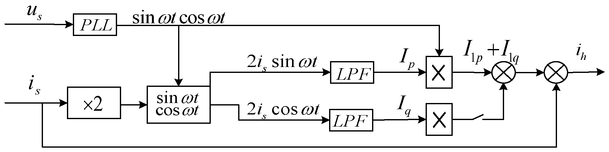
2. Harmonic Detection Method Combining LMS/LMF Adaptive Algorithm

As the three-phase system detection algorithm, the i p i q harmonic detection method based on instantaneous reactive power theory cannot be directly applied to the single-phase systems [11], so the three-phase construction method is adopted with the following procedure.
The single-phase voltage is expressed as u s ( t ) = U m sin ω t and the periodic non-sinusoidal current with harmonics is represented as:
i s t = n = 1 I n sin ω t + φ n = I 1 cos φ 1 sin ω t +   I 1 sin φ 1 cos ω t + n = 2 I n sin n ω t + φ n
With the active fundamental current of i 1 p ( t ) = I 1 cos φ 1 sin ω t and the harmonic current of i h t = I n sin n ω t + φ n , the fundamental reactive current can be obtained as i 1 a ( t ) = I 1 sin φ 1 cos ω t , and the a-phase current is constructed:
i α t = i s t = I 1 sin ω t + φ 1 + n = 2 i a n
Subsequently, inverting i α ( t ) and delaying π / ( 3 ω ) yields:
i c t = I 1 sin ω t π 3 ω + φ 1 + n = 2 i c n   = I 1 sin ω t + φ 1 + 2 π 3 + n = 2 i c n
i b t = i a t i c t = I 1 sin ω t + φ 1 2 π 3 + n = 2 i b n
The three-phase current i a , i b , i c can be constructed and transformed by d q coordinates. Based on the above construction results, the single-phase i p i q detection method can be explored, its principle is shown in Figure 1 [11]. The current is transformed by d q coordinates to obtain the fundamental active amplitude I p and fundamental reactive amplitude I q , and its DC components I p ¯ and I q ¯ are obtained by the LPF with the cut-off frequency lower than the fundamental frequency, and then the instantaneous fundamental active current I 1 cos φ 1 sin ω t and instantaneous fundamental reactive current I 1 sin φ 1 cos ω t are obtained by multiplying the fundamental sine and cosine sin ω t cos ω t , so as to obtain the system harmonic and reactive currents.
The phase difference between the fundamental co-channel signal and the actual fundamental wave is φ , the sine and cosine signals are sin ω t + φ and cos ω t + φ , respectively. 0.5 ( I p cos φ + I q sin φ ) and 0.5 ( I q cos φ + I p sin φ ) can be obtained by multiplying it with the load current through the gain and low-pass filter link, and multiply it with the sine and cosine of the fundamental then add to obtain:
I p cos φ + I q sin φ × sin ( ω t + φ ) + I q cos φ I p sin φ × cos ( ω t + φ ) = I p sin ω t + I q cos ω t = I 1 sin ( ω t + φ )
The result is the fundamental current I a f and the harmonic current i h calculated from the load current. The performance of the harmonic detection method is influenced by the low-pass filtering link [12], and the commonly used Butterworth II -structure filter cannot balance the filtering accuracy and convergence speed, while the adaptive filter has a simple computational process and better stability and adaptability [13]. Among the adaptive algorithms, the LMF algorithm has poor steady-state performance but good convergence rate, and the LMS algorithm has the same contradiction between steady-state performance and convergence speed when the step size is fixed [14]. The new fixed step size adaptive filter is proposed based on the two adaptive algorithms, and its performance function is set as
J n = 1 r n E e n 2 + r n E e n 4
In the above equation: r n is the proportional coefficient, which determines whether the filter chooses LMS or LMF algorithm. If r n = 1 , the LMF algorithm is chosen, and if r n = 0 , the result is reversed.
e n , i p n , x n can be set to be stationary parameters and e n is independent of x n , which leads:
e n = i p n y n = i p n w n x n
Using gradient estimation to update the weight w n :
w n + 1 = w n μ J n w n
Bringing Equations (7) and (8) into Equation (6) yields the weight update equation.
w n + 1 = w n + 2 μ 1 r n + 2 r n e n 2 e n x n
The proportional coefficient r n is updated by the forgetting factor and the normalization method:
r n + 1 = a r n + b q n 2
q n + 1 = c q n + ( 1 c ) e n e n 1 i p n i p ( n 1 )
Equations (9)–(11) constitute the fixed step size adaptive algorithm. The parameter μ in the formula is the step size, and a , b , c represents the forgetting parameter, which is the constant with the value of 0~1, and indicating the influence of the historical control signal on the real-time state. The autocorrelation estimation results of the historical error signal e n 1 and the real-time signal e n can adjust the proportional coefficient and reduce the signal-to-noise ratio of the system. The error of the weight vector w n increases when its input signal i p n changes, 2 r n 1 r n , the system uses the LMF algorithm. If i p n enters the steady state, then w n is close to the near-optimal value. 2 r n 1 r n , the system is converted to the LMS algorithm. It can be seen that the algorithm can choose the applicable algorithm by adjusting the proportional coefficient according to the original signal. Considering the stability of the algorithm, r n is usually restricted to take values between 0 and 1. If r n is close to 1, it means that the adaptive algorithm has good dynamic convergence performance, and if it is close to 0, it takes into account the steady-state performance and convergence speed. This paper takes r max = 0.9 and r min = 0.1 .

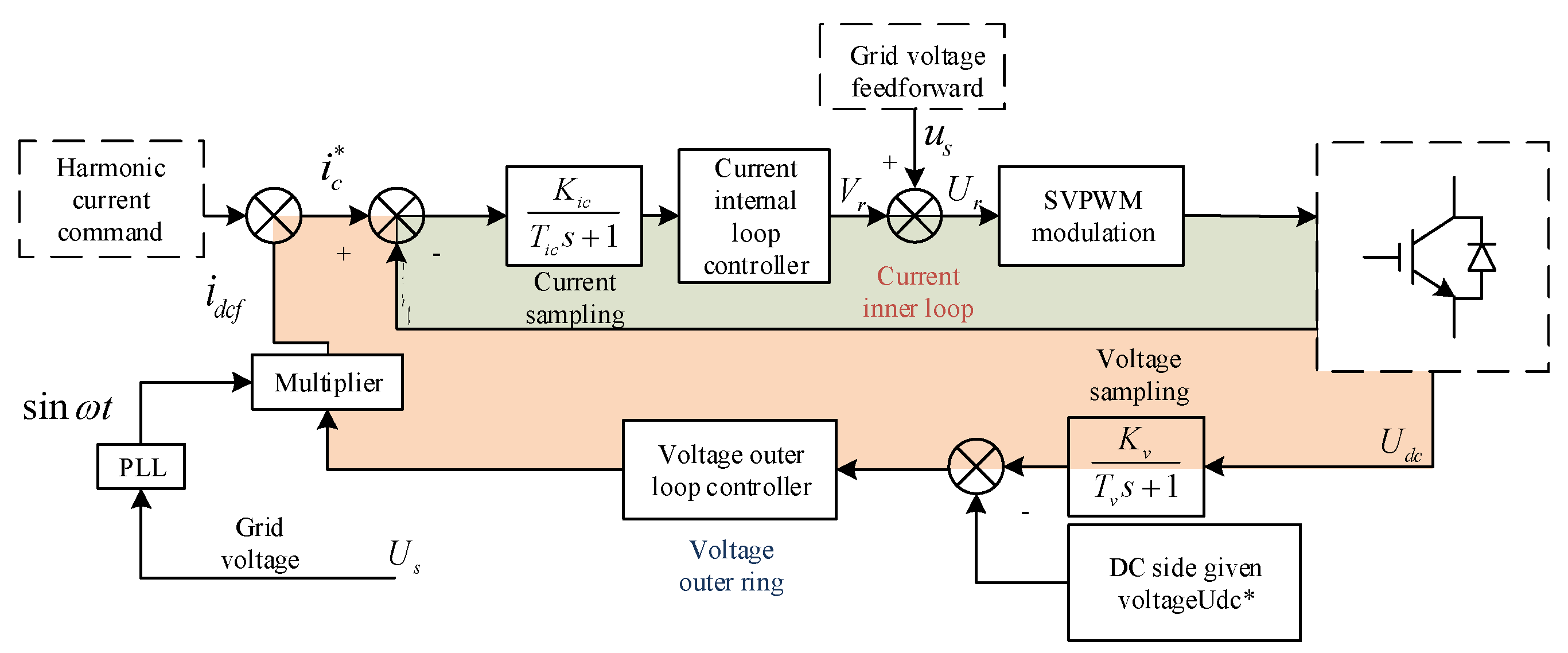
3. Single-Phase PAPF Composite Control Strategy

3.1. Repetition Control Principle

To realize the harmonic compensation function of the single-phase PAPF, the control system needs to have good stability and dynamic tracking performance. The system adopts the double closed-loop composite strategy of PI control combined with repetitive control to complete harmonic current tracking and compensation.
Single-phase PAPF needs to track signals with the same frequency or integer multiples of the fundamental wave, and the signal can be tracked without static errors by adding the co-channel s -domain model to the controller [15]. It is difficult to set the corresponding internal model for each frequency in the complex harmonic in the engineering level, so the repetition control is introduced to solve the problem. The repetition controller kernel is shown in Equation (12).
G r p ( s ) = c ( s ) e ( s ) = 1 1 e T s
For the single-phase PAPF system, it is transformed into the form of frequency domain. ω = 2 π n × 50 , k = 1 , 2 , 3 :
G r p j ω = c j ω e j ω = 1 1 e j n = 2 k + 1 2 n π = 1 1 1 =
It is known that all frequency compensation currents in the internal mode system have infinite gain [16].

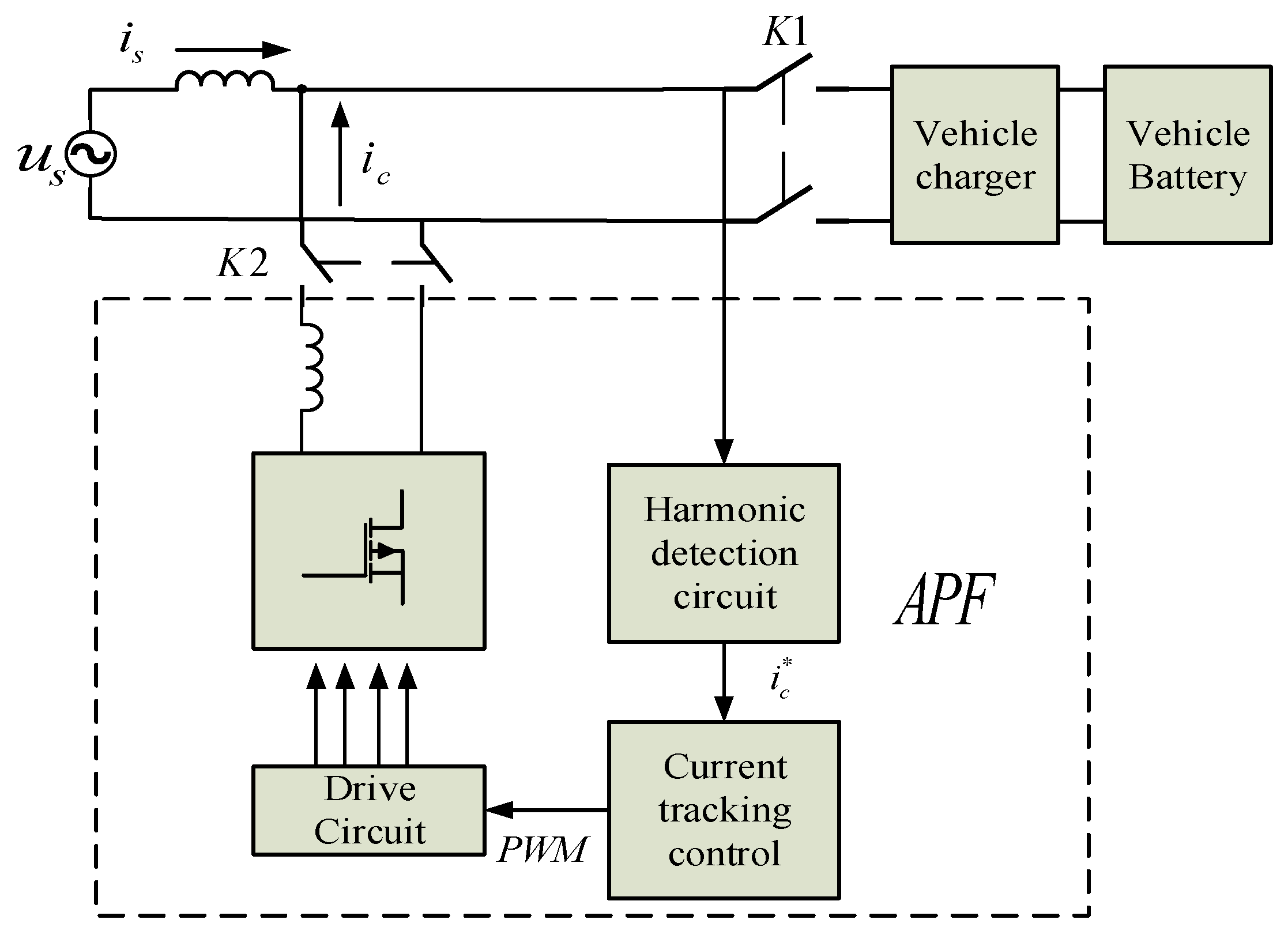
3.2. Filter System Working Principle and Compound Control Strategy

The traditional PI controller can achieve no static-error tracking of step signals due to its integral link with infinite gain for DC signals, but it cannot produce large gain for high-frequency signals [17,18,19]. For the inner loop current control, the controller needs to have infinite gain for harmonics to achieve accurate tracking, and the dynamic response ability of PI controller can be improved by combining with repetitive control theory, which is suitable for single-phase PAPF. The workflow of PAPF is shown in Figure 2, and the composite control process is shown in Figure 3.
The APF system is connected in parallel at the rear end of the AC charging post power line. When the charging pile is connected to the vehicle, K1 closes to start charging, while K2 also closes and the charging post is connected to the APF. U s is the grid voltage, i s is the grid current, and i c is the compensation current output from the APF. The system detects the load current through the current detection circuit, so as to extract the harmonics in it and get the modulation command of the output current. The control circuit output the PWM signal to enable the inverter to generate the corresponding compensation current.
During the control process shown in Figure 3, the sum of the DC-side current command i d c f and the harmonic current command i h is the total current command i c * . The current inner loop controller derives the voltage control quantity V r by adjusting the difference between it and the feedback current i c . The total voltage U r is obtained by adding the voltage feedback quantity. After the total voltage is modulated by space vector pulse width modulation (SVPWM), the modulating signal is output to complete the DC-side voltage regulation and generate the compensation current.

4. Harmonic Detection Simulation and Prototype Experiment

The harmonic detection situation is simulated based on MATLAB/SIMULINK. The single-phase uncontrolled rectifier bridge circuit with resistive inductive load is used as the harmonic source, and the total amount of harmonics generated can be obtained by the i p i q method based on instantaneous reactive power theory. In the detection process, the Butterworth filter and the new fixed-step adaptive filter are respectively used in the low-pass filtering link, and the simulation parameters are set as shown in Table 1. The cut-off frequency of the low-pass filter is taken as f c =   20 Hz , and the fixed-step adaptive filter takes the parameters a = 0.9 , b = 0.1 , c = 0.8 . The separated DC component I p ¯ is compared with the single-phase current component, which is the a-phase fundamental current I a f . The output waveforms are shown in Figure 4 and Figure 5.
It can be seen that the DC component and the fundamental current produce sudden changes at 0.06 s, which reflects the dynamic performance of the low-pass filter. The adjustment time of the Butterworth filter is about 0.06 s, and its steady-state waveform is relatively smooth, but there is overshoot phenomenon in the dynamic adjustment process. The regulation time of fixed-step adaptive filter is about 0.02 s, and its response is more sensitive. To better verify the effect of the adaptive filter on harmonic detection performance, the TMS320 development board and semi-physical simulation platform are used to carry out the prototype experiments. The host computer is connected to the RT-LAB platform through the network cable, which can receive data and compile the above SIMULINK model, while the lower computer is responsible for running the model and executing I/O to realize interaction with external hardware such as oscilloscopes. The prototype is shown in Figure 6. The principle of the harmonic detection experiment is shown in Figure 1, in which the LPF, PLL, sin ω t cos ω t , and adaptive algorithm are realized by the built-in DSP software of the platform, and the current waveforms is recorded by the external oscilloscope. For the convenience of comparison, the various output waveforms of the two filters are shown in Figure 7 and Figure 8, which are the load current i a , fundamental current I a f , I p obtained by d q transform, DC component I p ¯ of the output of the fixed-step adaptive filter, and harmonics i h .
It is demonstrated that the fixed-step adaptive low-pass filter combined with LMS/LMF can extract the DC component accurately, the load current changes rapidly and the transition process is less than one power cycle. The fundamental current has good sinusoidality, and it combines good stability and response speed compared with the conventional Butterworth filter.

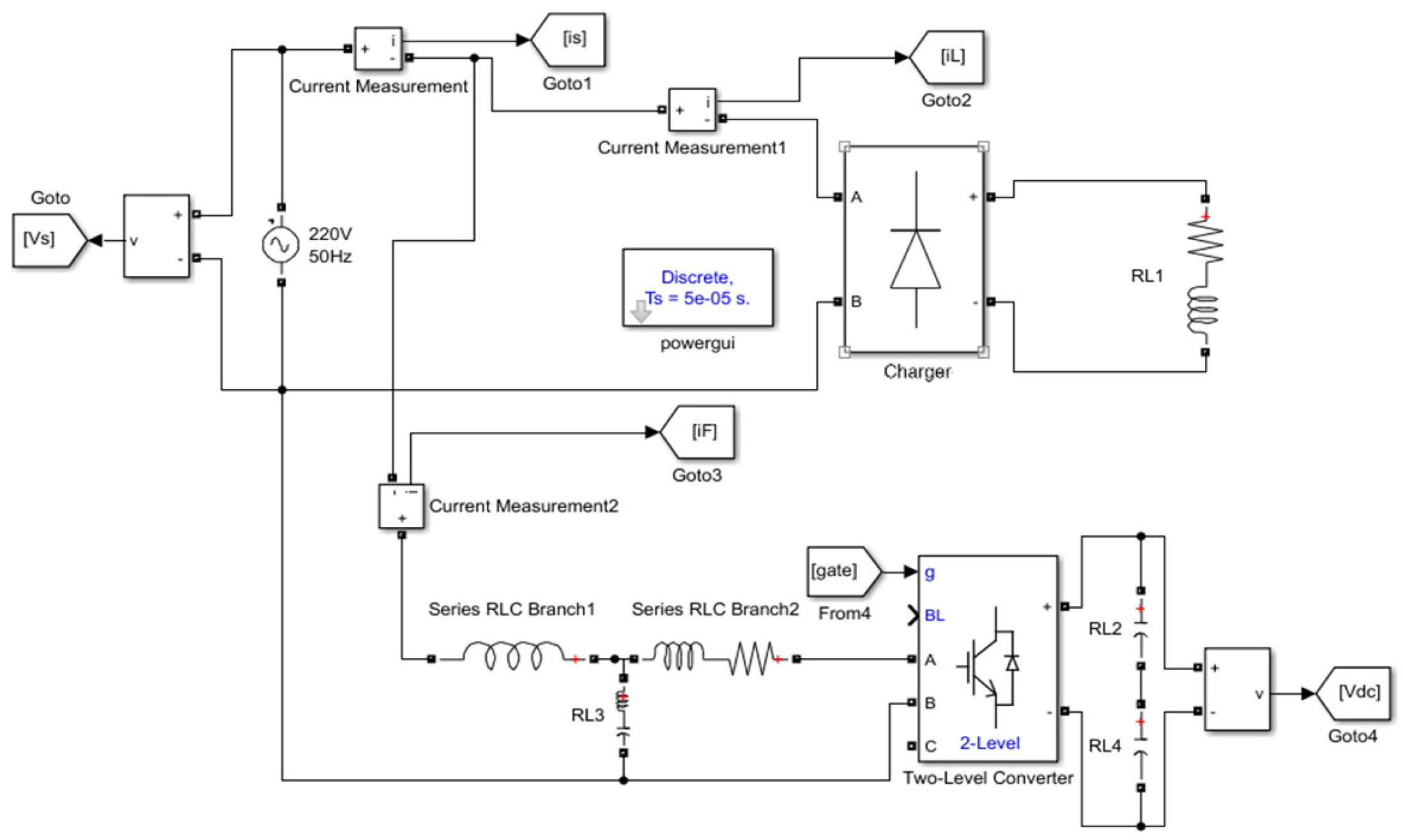
5. Simulation of Composite Control System for Single-Phase PAPF System

According to the overall algorithm flow shown in Figure 3, the simulation of the single-phase PAPF system is carried out, the overall block diagram is shown in Figure 9, the parameters are shown in Table 2, and the load mutation is set at 0.1 s.
The control compensation process performed after harmonic detection uses the composite control strategy. To verify the enhancement effect of its harmonic compensation performance, the effect of current compensation is compared and analyzed with that of conventional PI control alone. The system harmonic management capability is verified by analyzing the THD. The simulated waveforms of each current during the conventional PI control are shown in Figure 10, the load current FFT analysis image is shown in Figure 11.
The Fast Fourier Transform (FFT) in MATLAB is used to analyze the spectrum of the transmission current waveforms, the total harmonic distortion is reduced to 13.56% after PI control, and the result is shown in Figure 12. The filtering effect is significant, but the tracking ability of higher harmonics is weak, which does not reach the national standard of 5%. Next, the simulation of the composite control process is carried out, and the current waveforms are shown in Figure 13, and the result of its FFT analysis is shown in Figure 14.
The grid current waveform is a smooth sinusoidal curve after the compensation of the compound control, which effectively eliminates the current burr and improves the limitation of PI control. The FFT spectrum analysis of the current after compensation shows that THD has been reduced to 3.51%, which meets the national standard and solves the problem of current distortion caused by harmonic pollution.

6. Conclusions

In this paper, the harmonic detection and control of the single-phase AC charging pile were studied. The new type of fixed-step adaptive filter was introduced in harmonic detection to improve the harmonic detection performance, and the composite control algorithm was adopted in the harmonic compensation. The following conclusions have been obtained through simulation analysis and prototype experiments.
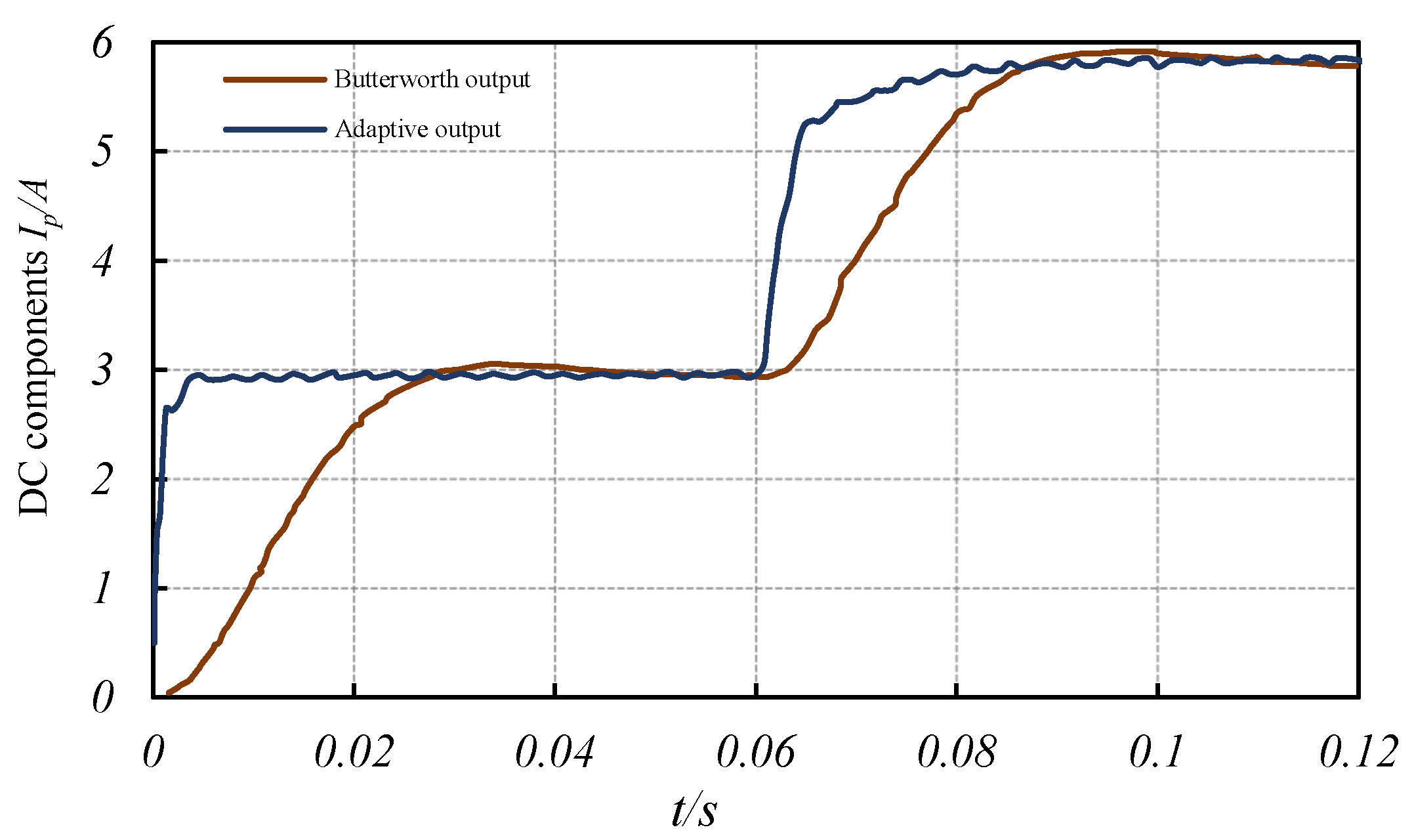
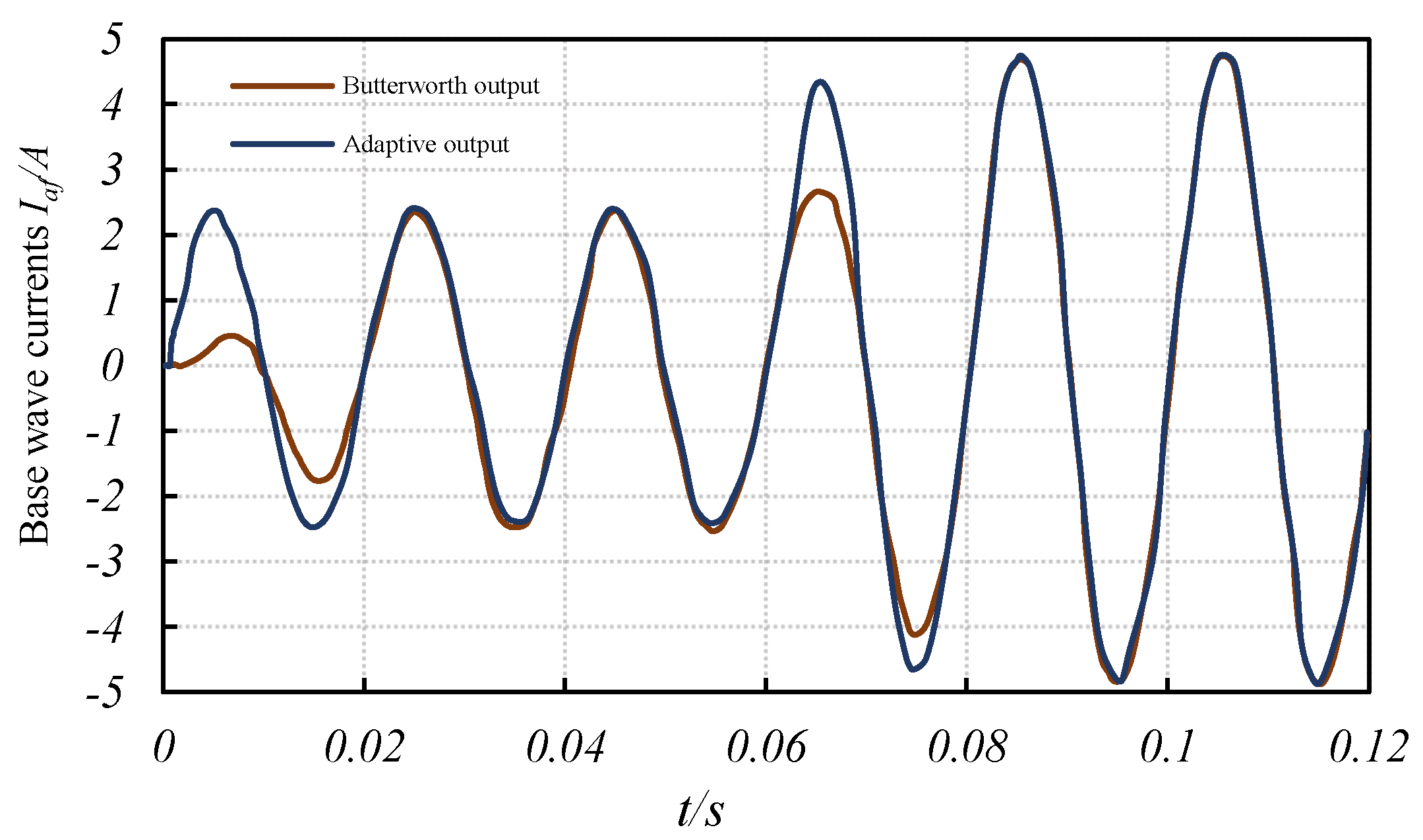
  • The hybrid adaptive filtering algorithm can adjust the proportion of LMS and LMF algorithms in the system weights according to the error changes and reasonably take into account the advantages of each algorithm. The improved method not only ensured the accuracy of harmonic detection, but also increased the response speed by 0.04 s, which improved the harmonic detection performance.
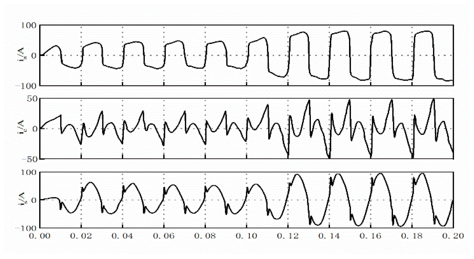
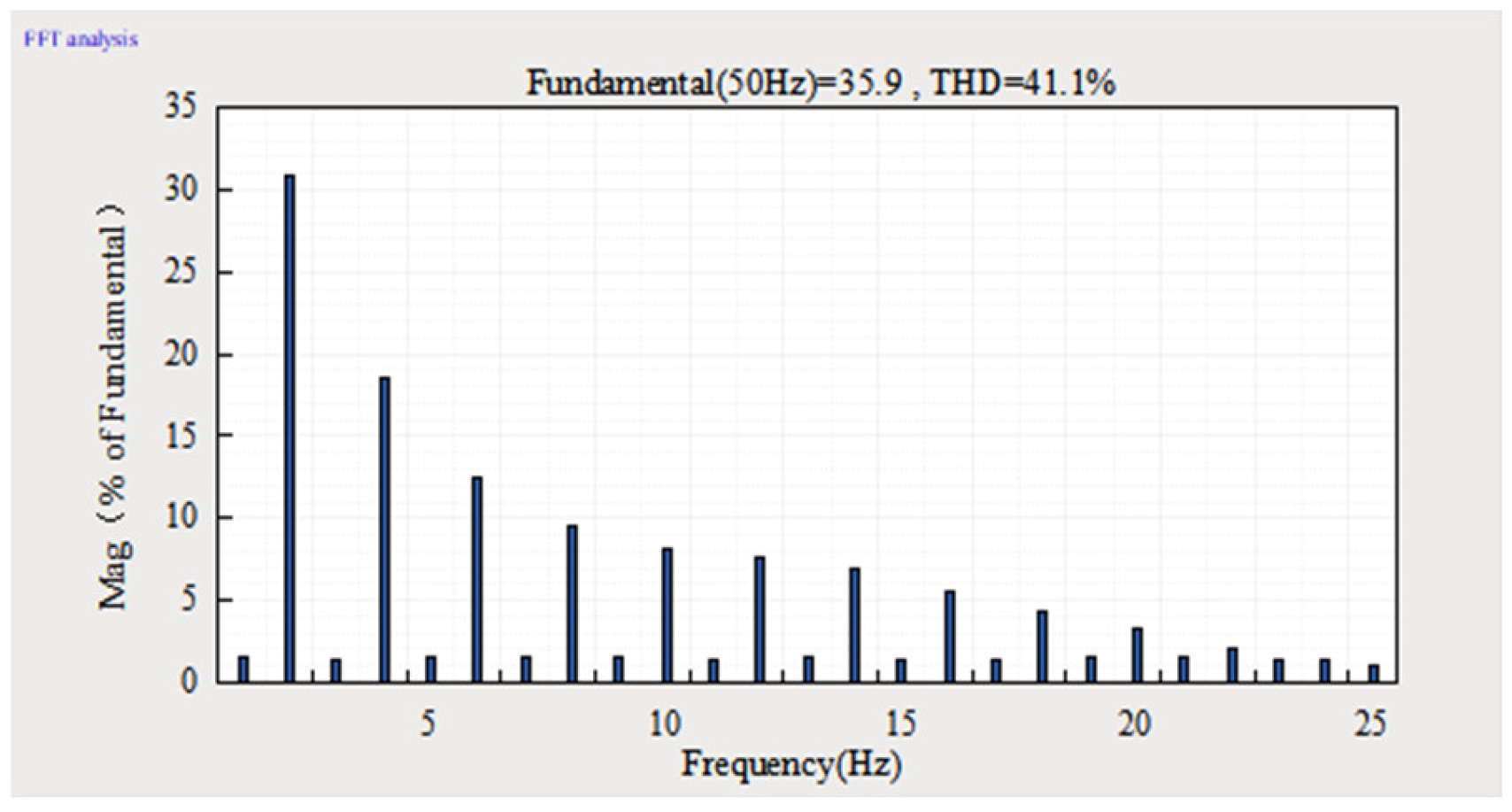
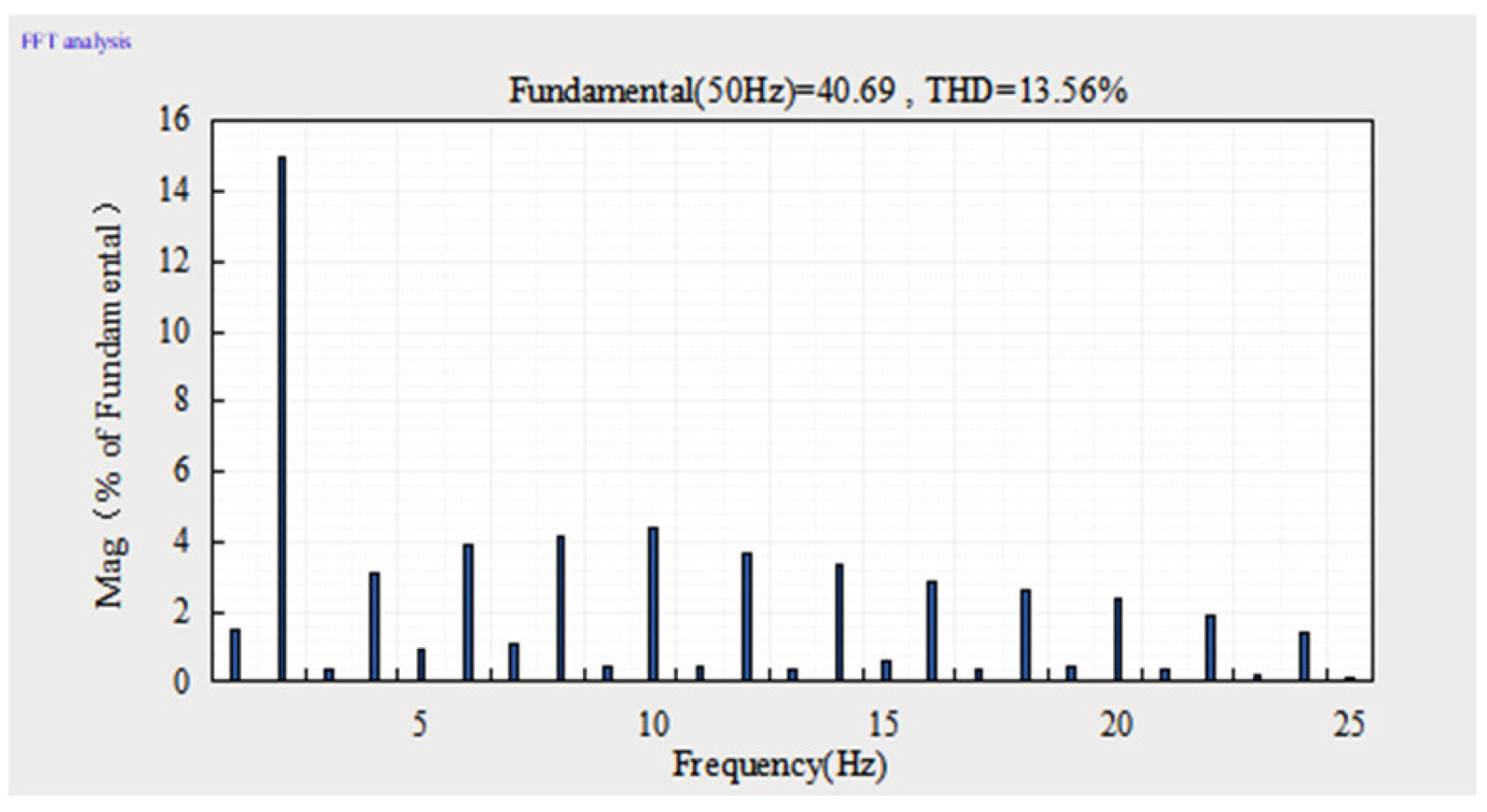
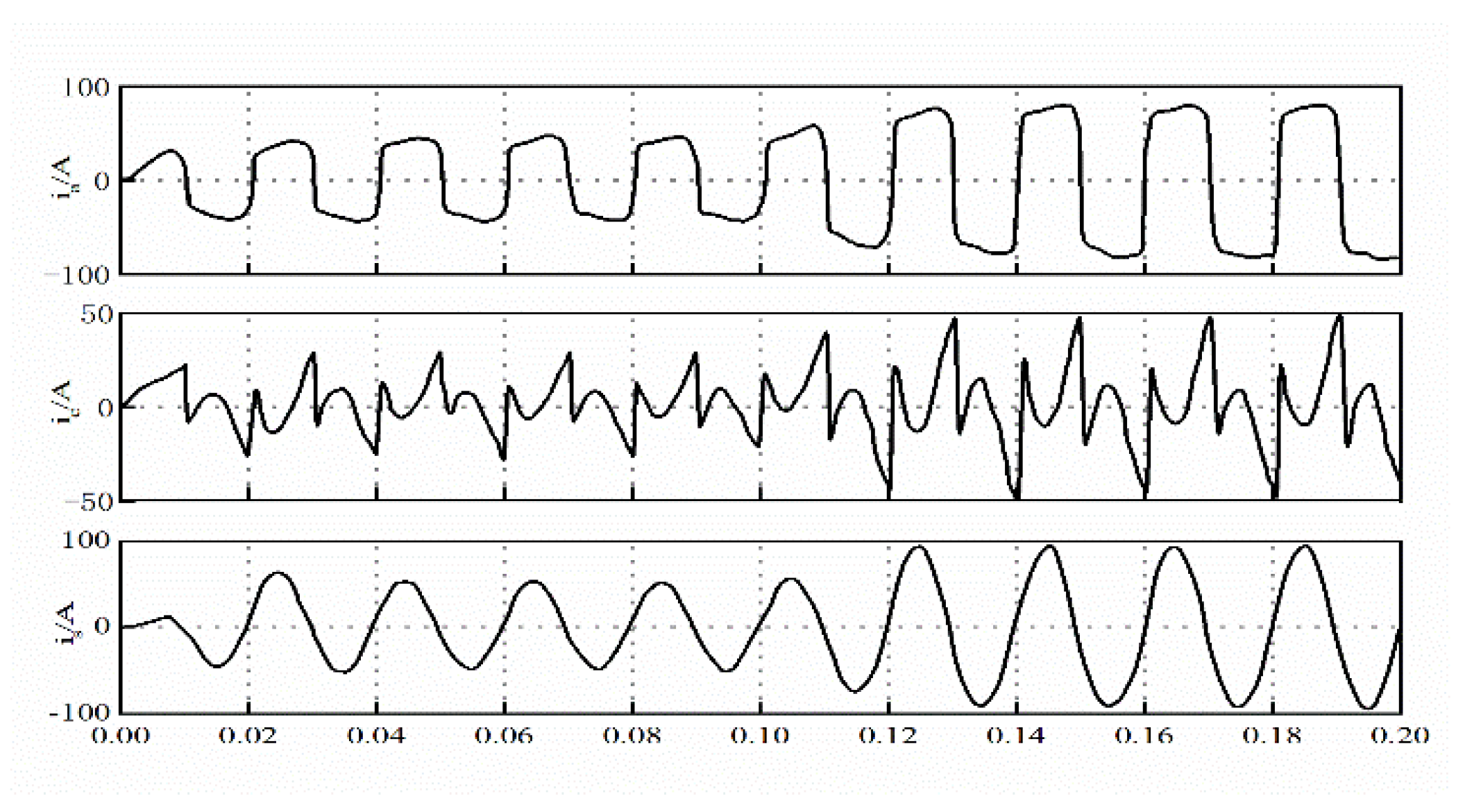
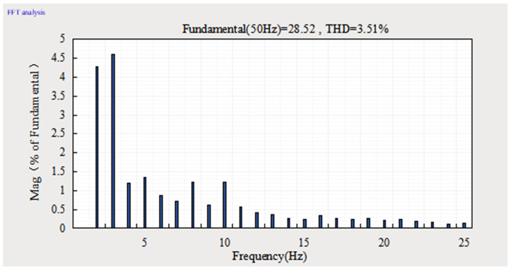
  • Compound control was used to complete the harmonic compensation and compare the compensation results. The grid current waveform curve was more rounded, and the system had obvious tracking in the first cycle of sudden load change and entered the steady state in the third cycle. After compensation, the harmonic content of the power grid current was reduced to below 5%, which was in line with national standards. The above results showed that the system has good dynamic response capability and better harmonic compensation performance.
  • Although the single PAPF system studied in this paper achieved good compensation, there are still some aspects that can be improved and are areas where future research can be initiated. The single harmonic detection technique used in this paper had the delay while performing the three-phase construction, which in practice was reflected in the extensive use of multipliers and the use of LPFs. In this paper, the LPF link had been improved but a single harmonic detection technique with better dynamic performance and detection accuracy can be designed without relying on the digital LPF in the future. In addition, although the combination of PI control and repetitive control had achieved relatively high dynamic and steady-state performance, further performance improvement and the use of other controllers with better dynamic performance instead of PI controllers are the focus of future research.

Author Contributions

Conceptualization, H.S. and G.Y.; methodology, H.S. and G.Y.; software, Y.W. and X.D.; validation, Y.Z., H.S. and G.Y.; data curation, H.S.; writing—original draft preparation, H.S.; writing—review and editing, Y.W. and S.Z.; supervision, G.Y.; project administration, Y.W. All authors have read and agreed to the published version of the manuscript.

Funding

This research was funded by the National Natural Science Foundation of China (Grant No. 52075305) and the Shandong Higher Education Youth Innovation Technology Support Program (Grant No. 2019KJB031).

Data Availability Statement

Not applicable.

Acknowledgments

The authors thank the National Natural Science Foundation of China and the China Huadian Group Huadian Zhangqiu Power Generation Co., Ltd. for support to this project.

Conflicts of Interest

The authors declare no conflict of interest.

References

  1. Chen, X.G.; Xiang, T.C.; Li, C.P.; Bi, Y.X. A Novel Active Power Filter Method for Single-phase Rectifiers in Charging Systems for Electric Vehicles. Electr. Drive 2021, 51, 14–21. [Google Scholar]
  2. Zhang, Y.; Lu, J.Z.; Li, B. New electric vehicle AC charge spots using active power filter. High Volt. Eng. 2011, 37, 7. [Google Scholar]
  3. Wu, J.Z.; Mei, F.; Chen, C. Harmonic detection method in power system based on empirical wavelet transform. Power Syst. Prot. Control 2020, 48, 8. [Google Scholar]
  4. Zhang, W.C. Design of AC Charging Pile System for Electric Vehicle and Research on Active Filter. Ph.D. Thesis, Anhui University of Technology, Maanshan, China, 2019. [Google Scholar]
  5. Peng, J.W. Research on Unexpected Harmonic Current Suppression Strategy of Single-Phase Parallel APF. Ph.D. Thesis, Huazhong University of Science and Technology, Wuhan, China, 2019. [Google Scholar]
  6. Zhou, W.J. Research and Design of Photovoltaic Charging Pile Based on Internet. Ph.D. Thesis, Guangxi University, Nanning, China, 2021. [Google Scholar]
  7. Chen, D.; Qiu, Q.H.; Yang, X.D.; Wang, J.; Ping, H.E.; Jin, Y.Q.; Zhang, Y.B. Harmonic suppression methods for different types of electric vehicle charging stations. J. Mech. Electr. Eng. 2017, 34, 922–926. [Google Scholar]
  8. Lu, K.; Diao, Q. Analysis of active power filter applications in different networks. Power Syst. Prot. Control 2015, 43, 143–149. [Google Scholar]
  9. Li, N.; Huang, M. Analysis on harmonics caused by connecting different types of electric vehicle chargers with power network. Power Syst. Technol. 2011, 35, 170–174. [Google Scholar]
  10. Shi, H.; Gong, X.J.; Chi, G.S.P.; Zhang, J.J. Research on finite control set model predictive control strategy of three-level APF. J. Phys. Conf. Ser. 2021, 1748, 32001. [Google Scholar] [CrossRef]
  11. Soomro, D.M.; Alswed, S.K.; Abdullah, M.N.; Radzi, N.H.b.M.; Baloch, M.H. Optimal design of a single-phase APF based on PQ theory. Int. J. Power Electron. Drive Syst. 2020, 11, 1360. [Google Scholar] [CrossRef]
  12. Wei, X.; Li, C.; Qi, M.; Luo, B.; Deng, X.; Zhu, G. Research on Harmonic Current Amplification Effect of Parallel APF Compensating Voltage Source Nonlinear Load. Energies 2019, 12, 3070. [Google Scholar] [CrossRef] [Green Version]
  13. Liu, S.Y. Design of Active Power Factor Correction and Control System for Charging Pile of Electric Vehicle. Ph.D. Thesis, Harbin University of Technology, Harbin, China, 2021. [Google Scholar]
  14. Shao, Z.G.; Xu, H.B.; Xiao, S.Y. Harmonic problems in a new energy power grid. Power Syst. Prot. Control 2021, 49, 178–187. [Google Scholar]
  15. Chen, Z.L. Research on Harmonic Current Detection and Tracking Control of Active Power Filter. Ph.D. Thesis, Jiangsu University, Zhenjiang, China, 2013. [Google Scholar]
  16. Li, G.; Ding, L. Design of simulation test platform for charging pile control system. J. Phys. Conf. Ser. 2020, 1550, 62004. [Google Scholar] [CrossRef]
  17. Xu, J.C.; Liu, X.; Shi, H.; He, W.S. Research of monitor system of electric vehicle charging pile based on ARM-Linux. Appl. Mech. Mater. 2012, 241–244, 2258–2262. [Google Scholar] [CrossRef]
  18. Caro, L.M.; Ramos, G.; Rauma, K.; Rodriguez, D.F.C.; Martinez, D.M.; Rehtanz, C. State of Charge Influence on the Harmonic Distortion from Electric Vehicle Charging. IEEE Trans. Ind. Appl. 2021, 57, 2077–2088. [Google Scholar] [CrossRef]
  19. Lucas, A.; Bonavitacola, F.; Kotsakis, E.; Fulli, G. Grid harmonic impact of multiple electric vehicle fast charging. Electr. Power Syst. Res. 2015, 127, 13–21. [Google Scholar] [CrossRef]
Figure 1. Harmonic and reactive current detection principle.
Energies 16 02817 g001
Figure 2. Single-phase PAPF working principle diagram.
Energies 16 02817 g002
Figure 3. Single-phase PAPF overall composite control block diagram.
Energies 16 02817 g003
Figure 4. DC components.
Energies 16 02817 g004
Figure 5. Base wave currents.
Energies 16 02817 g005
Figure 6. Prototype object.
Energies 16 02817 g006
Figure 7. Experimental diagram of fixed-step adaptive filter.
Energies 16 02817 g007
Figure 8. Experimental diagram of Butterworth filter.
Energies 16 02817 g008
Figure 9. Single-phase PAPF simulation model.
Energies 16 02817 g009
Figure 10. PI control load current, compensation current, and grid current waveforms.
Energies 16 02817 g010
Figure 11. Load current FFT analysis.
Energies 16 02817 g011
Figure 12. Current FFT analysis after PI control compensation.
Energies 16 02817 g012
Figure 13. Composite control of each current waveform.
Energies 16 02817 g013
Figure 14. Current FFT analysis after compound control compensation.
Energies 16 02817 g014
Table 1. Simulation parameters.
ParametersNumerical Value
Voltage value U s 220 V/50 Hz
Load resistance R d 136 Ω
Load inductance L d 30 mH
Load Surge Resistance R d 68 Ω
Load Sudden Change Inductance L d 15 mH
Table 2. System simulation parameters.
ParametersNumerical Value
Grid voltage value U s 220 V/50 Hz
Filter Capacitor C 36 μF
DC side capacitance C d c 3000 μF
Filter Inductors L 1 0.315 mH
Grid-side inductance L 2 0.104 mH
Modulation methodSVPWM
Disclaimer/Publisher’s Note: The statements, opinions and data contained in all publications are solely those of the individual author(s) and contributor(s) and not of MDPI and/or the editor(s). MDPI and/or the editor(s) disclaim responsibility for any injury to people or property resulting from any ideas, methods, instructions or products referred to in the content.

