
A Two-Layer Optimization Strategy for Battery Energy Storage Systems to Achieve Primary Frequency Regulation of Power Grid


Abstract
1. Introduction
2. Regional Grid Primary FM Model with Multiple BESSs
3. Integrated Control Mode Based on VIC and VDC
3.1. Control Structure of VIC and VDC
3.2. Integrated Control Strategy Based on VIC and VDC
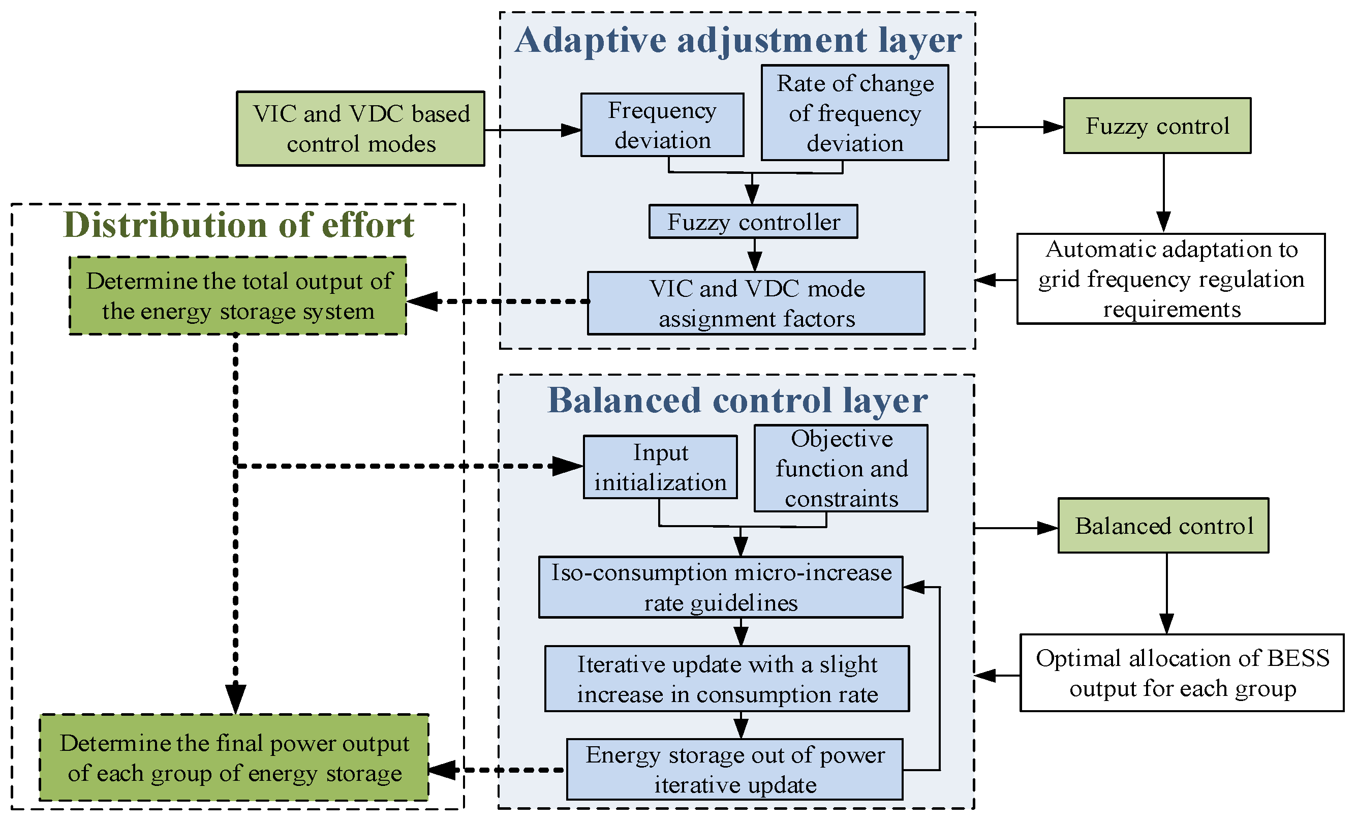
4. Double-Layer Control Strategy for Primary Frequency Modulation
4.1. Two-Tier Control Structure
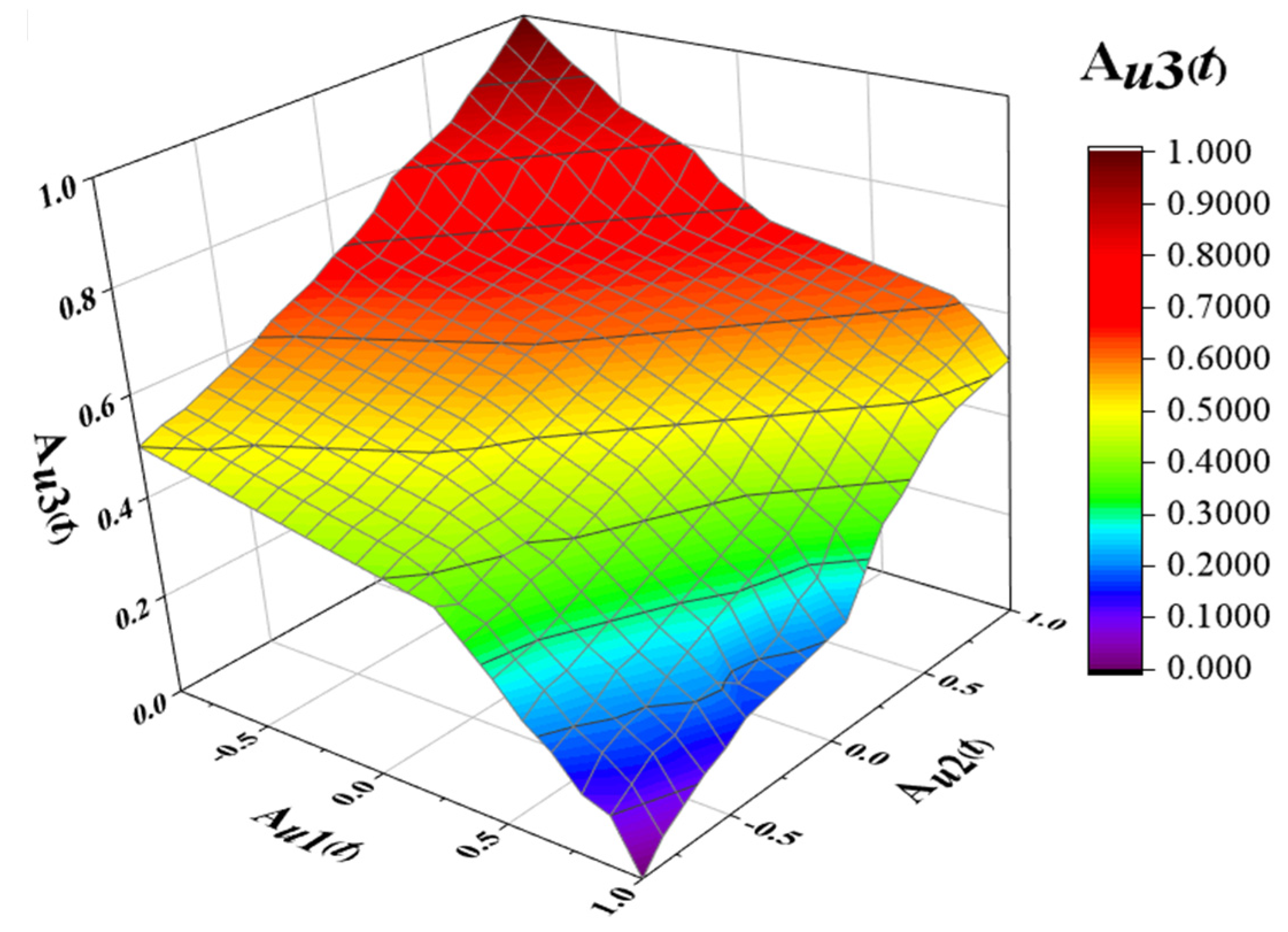
4.2. Adaptive Regulation Layer
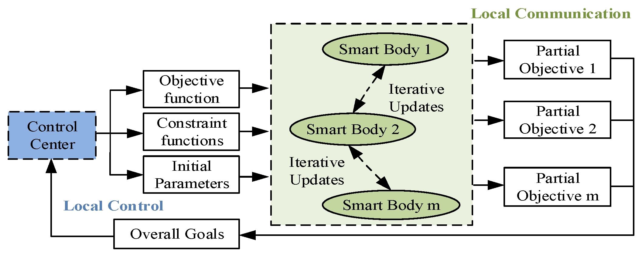
4.3. Balanced Control Layer
4.3.1. Objective Function and Constraint Function
4.3.2. Initialization Settings
4.3.3. Iterative Update
4.3.4. Balancing Control Process
- Step 1:
- In the FM process, define the objective function based on the total cost of the BESS and consider the charge state limit and charge/discharge power limit of energy storage as the objective function’s constraint function.
- Step 2:
- Set the equivalent consumption micro-increase rate λ0Bj,m and the energy storage frequency adjustment power P0Bj,m to their starting values, while setting the algorithm’s initial iteration number n to 0.
- Step 3:
- Each group of BESS is compared with the equal consumption micro-increase rate of the neighboring BESS and if the consistency condition is satisfied, it means that the storage and the neighboring storage have reached local optimization; otherwise, its equal consumption micro-increase rate is updated according to Equations (18) and (19), and the updating process requires the neighboring BESSs to exchange and update their equal consumption micro-increase rates in the process of FM control, so that the marginal cost of the neighboring BESS is consistent and at the same time equilibrium is reached among the groups of BESSs in the control network.
- Step 4:
- The FM power of each group of BESS is updated according to the updated equal consumption micro-increase rate λnj,m, and after substituting the updated equal consumption micro-increase rate into Equation (16), the FM output power Pnj,m is updated in combination with Equation (20); when all BESSs update the FM power and output according to the equal consumption micro-increase rate consistency criterion, one action of FM is completed and the whole control network reaches stability.
- Step 5:
- Perform the timer’s preset sampling interval Δt, and determine whether the timer’s preset value is reached; if so, end; otherwise, n = n+1; return to Step 3.
5. Simulation Analysis
5.1. Simulation Parameters
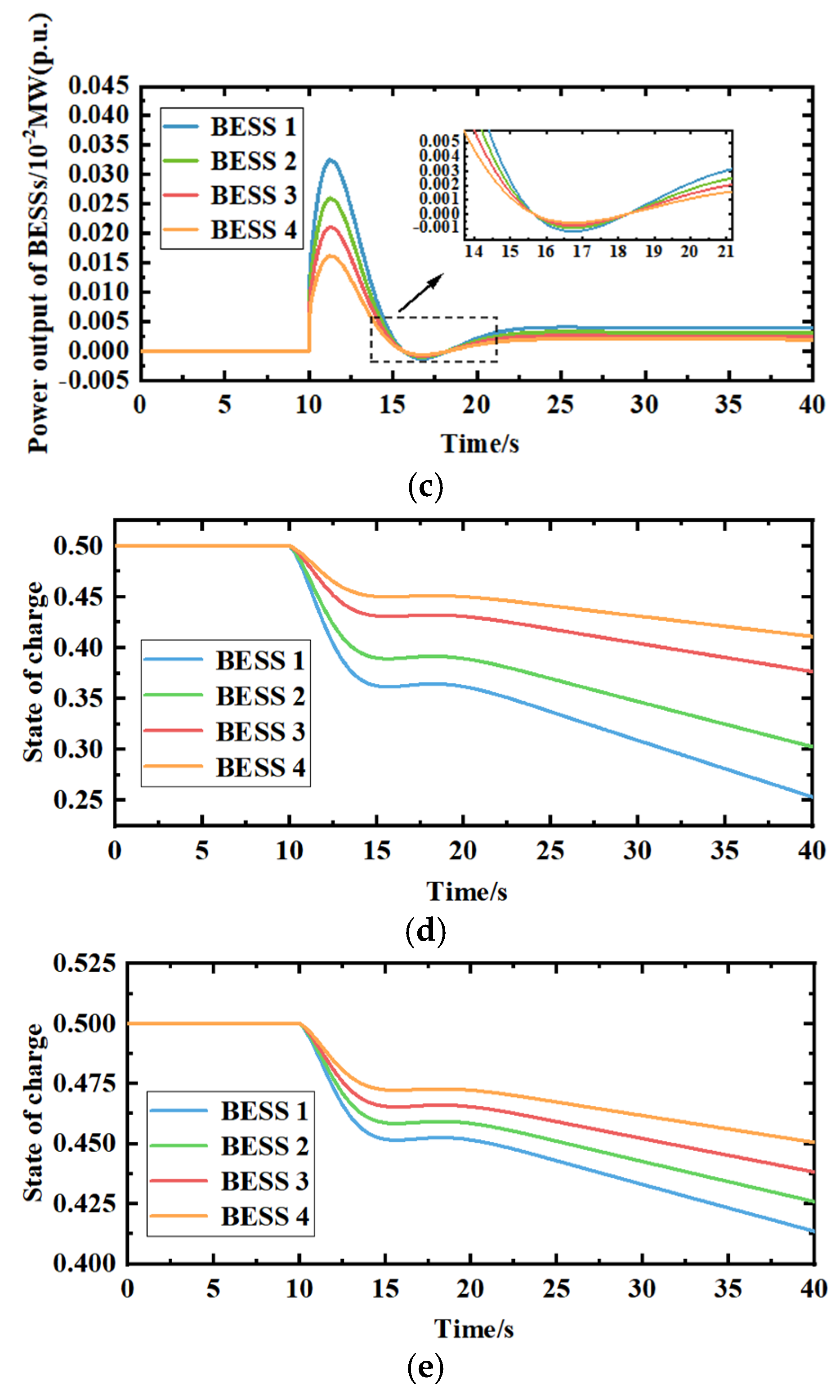
5.2. Step Perturbation
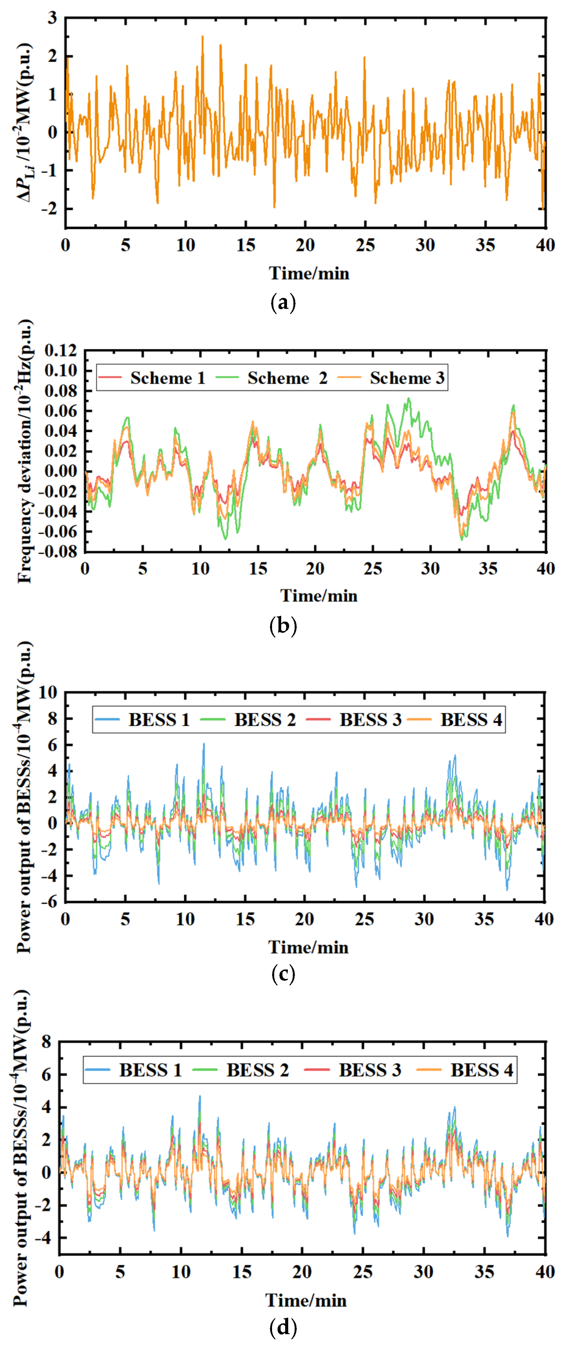
5.3. Continuous Perturbation
5.4. Comparison of Results
6. Conclusions
Author Contributions
Funding
Data Availability Statement
Conflicts of Interest
References
- Zhao, T.; Parisio, A.; Milanović, J.V. Location-Dependent Distributed Control of Battery Energy Storage Systems for Fast Frequency Response. Int. J. Electr. Power Energy Syst. 2021, 125, 106493. [Google Scholar] [CrossRef]
- Shi, Y.; Xu, B.; Wang, D.; Zhang, B. Using Battery Storage for Peak Shaving and Frequency Regulation: Joint Optimization for Superlinear Gains. IEEE Trans. Power Syst. 2018, 33, 2882–2894. [Google Scholar] [CrossRef]
- Abouzeid, S.I.; Guo, Y.; Zhang, H. Coordinated Control of the Conventional Units, Wind Power, and Battery Energy Storage System for Effective Support in the frequency regulation service. Int. Trans. Electr. Energy Syst. 2019, 29, e2845. [Google Scholar] [CrossRef]
- Kumar, Y.A.; Kim, H.J. Effect of Time on a Hierarchical Corn Skeleton-Like Composite of CoO@ZnO as Capacitive Electrode Material for High Specific Performance Supercapacitors. Energies 2018, 11, 3285. [Google Scholar] [CrossRef]
- Moniruzzaman, M.; Anil Kumar, Y.; Pallavolu, M.R.; Arbi, H.M.; Alzahmi, S.; Obaidat, I.M. Two-Dimensional Core-Shell Structure of Cobalt-Doped@MnO2 Nanosheets Grown on Nickel Foam as a Binder-Free Battery-Type Electrode for Supercapacitor Application. Nanomaterials 2022, 12, 3187. [Google Scholar] [CrossRef]
- Lee, J.; Kim, J.-M.; Yi, J.; Won, C.-Y. Battery Management System Algorithm for Energy Storage Systems Considering Battery Efficiency. Electronics 2021, 10, 1859. [Google Scholar] [CrossRef]
- Wang, K.; Qiao, Y.; Xie, L.; Li, J.; Lu, Z.; Yang, H. A Fuzzy Hierarchical Strategy for Improving Frequency Regulation of Battery Energy Storage System. J. Mod. Power Syst. Clean Energy 2021, 9, 689–698. [Google Scholar] [CrossRef]
- Hollinger, R.; Diazgranados, L.M.; Wittwer, C.; Engel, B. Optimal Provision of Primary Frequency Control with Battery Systems by Exploiting All Degrees of Freedom within Regulation. Energy Procedia 2016, 99, 204–214. [Google Scholar] [CrossRef]
- Su, D.; Lei, Z. Optimal configuration of battery energy storage system in primary frequency regulation. Energy Rep. 2021, 7, 157–162. [Google Scholar] [CrossRef]
- Wang, X.; Ying, L.; Wen, K.; Lu, S. Bi-level non-convex joint optimization model of energy storage in energy and primary frequency regulation markets. Int. J. Electr. Power Energy Syst. 2022, 134, 107408. [Google Scholar] [CrossRef]
- Jiang, X.; Jin, Y.; Zheng, X.; Hu, G.; Zeng, Q. Optimal Configuration of Grid-Side Battery Energy Storage System under Power Marketization. Appl. Energy 2020, 272, 115242. [Google Scholar] [CrossRef]
- Tang, Y.; Yang, C.; Yan, Z.; Xue, Y.; He, Y. Coordinated Control of a Wind Turbine and Battery Storage System in Providing Fast-Frequency Regulation and Extending the Cycle Life of Battery. Front. Energy Res. 2022, 10, 927453. [Google Scholar] [CrossRef]
- Turk, A.; Sandelic, M.; Noto, G.; Pillai, J.R.; Chaudhary, S.K. Primary Frequency Regulation Supported by Battery Storage Systems in Power Systems Dominated by Renewable Energy Sources. J. Eng. 2019, 2019, 4986–4990. [Google Scholar] [CrossRef]
- Meng, G.J.; Zhang, F.; Zhao, Y.; Wu, T.; Ma, F.Y. Optimal integrated control strategy for battery energy storage participation in grid primary frequency regulation. New Technol. Electr. Power 2021, 40, 43–49. [Google Scholar]
- Wang, W.Y.; Li, Y.; Cao, Y.; Xu, Z.W.; Tan, Y. Adaptive sag control strategy for multi-terminal flexible DC transmission system participating in grid frequency regulation. Power Syst. Autom. 2017, 41, 142–149+161. [Google Scholar]
- Zhu, Z.; Ye, C.; Wu, S. Comprehensive Control Method of Energy Storage System to Participate in Primary Frequency Regulation with Adaptive State of charge recovery. Int. Trans. Electr. Energy Syst. 2021, 31, e13220. [Google Scholar] [CrossRef]
- Wang, M.Q. Research on Battery Energy Storage System Participation in System Primary Frequency Regulation Control Strategy. Master’s Thesis, School of Electrical and Information Engineering, Northeastern Electric Power University, Jilin, China, 2022. (In Chinese). [Google Scholar] [CrossRef]
- Li, P.Q.; Feng, Y.H.; Li, X.R.; Tan, Z.X.; Yang, B.; Huang, J.Y. Energy storage battery participation in grid primary frequency regulation control strategy considering ultra-short-term load forecasting. Power Syst. Autom. 2019, 43, 87–93+148. [Google Scholar]
- Li, X.R.; Cui, X.W.; Huang, J.Y.; Li, S.J.; Meng, Y. Adaptive control strategy for battery storage power supply participation in grid primary frequency regulation. J. Electr. Eng. Technol. 2019, 34, 3897–3908. [Google Scholar] [CrossRef]
- Yang, B.; Weng, L.; Li, Y.; Zhang, Y.; Zhou, C. Research on Coordinated Control Strategy of Energy Storage Participating in Primary Frequency Regulation Considering Frequency Deviation Change Rate. J. Phys. Conf. Ser. 2021, 1750, 012034. [Google Scholar] [CrossRef]
- Fan, F.; Xu, Y.; Zhang, R.; Wan, T. Whole-Lifetime Coordinated Service Strategy for Battery Energy Storage System Considering Multi-Stage Battery Aging Characteristics. J. Mod. Power Syst. Clean Energy 2022, 10, 689–699. [Google Scholar] [CrossRef]
- Liu, B.; Chen, Z.; Yang, S.; Wang, Y.; Yang, K.; Lu, C. Primary frequency regulation scheme applicable to LCC-VSC series hybrid HVDC considering AC voltage stability at receiving end. Int. J. Electr. Power Energy Syst. 2022, 140, 108071. [Google Scholar] [CrossRef]
- Active participation of variable speed wind turbine in inertial and primary frequency regulations. Electr. Power Syst. Res. 2017, 147, 174–184. [CrossRef]
- Zhang, J.F.; Su, Y.; Sun, J.D.; Zheng, K.K.; Mei, J.; Wang, Z.X.; Lu, S.B.; Yue, H.F. Optimization and experimental analysis of AGC control strategy for grid-side electrochemical energy storage power plants. J. Power Sci. Technol. 2022, 37, 173–180. [Google Scholar] [CrossRef]
- Stroe, D.I.; Knap, V.; Swierczynski, M.; Stroe, A.I.; Teodorescu, R. Operation of a Grid-Connected Lithium-Ion Battery Energy Storage System for Primary Frequency Regulation: A Battery Lifetime Perspective. IEEE Trans. Ind. Appl. 2017, 53, 430–438. [Google Scholar] [CrossRef]
- Wang, Y.F.; Yang, M.C.; Xue, H.; Zhang, Y.H.; Mi, Y. Adaptive integrated control strategy for primary frequency regulation of battery energy storage system with SOC. Power Autom. Equip. 2021, 41, 192–198+219. [Google Scholar] [CrossRef]
- Ming, T.T.; Zhao, J.; Wang, X.L. SOC estimation of a lithium battery under high pulse rate condition based on improved LSTM. Power Syst. Prot. Control 2021, 49, 144–150. [Google Scholar]
- Li, S.; Xu, Q.; Xia, Y. Comprehensive setting and optimization of Dead-Band for BESS participate in power grid primary frequency regulation. Int. J. Electr. Power Energy Syst. 2022, 141, 108195. [Google Scholar] [CrossRef]
- Wen, K.; Li, W.; Yu, S.S.; Li, P.; Shi, P. Optimal intra-day operations of behind-the-meter battery storage for primary frequency regulation provision: A hybrid lookahead method. Energy 2022, 247, 123482. [Google Scholar] [CrossRef]
- Hu, Z.; Gao, B.; Sun, R. An active primary frequency regulation strategy for grid integrated wind farms based on model predictive control. Networks 2022, 32, 100955. [Google Scholar] [CrossRef]
- Li, J.H.; Gao, Z.; Ying, H.; Lin, L.; Shen, B.X.; Fan, X.K. Frequency control strategy of energy storage primary regulation based on dynamic sag coefficient and SOC base point. Power Syst. Prot. Control 2021, 49, 1–10. [Google Scholar] [CrossRef]
- Andrenacci, N.; Chiodo, E.; Lauria, D.; Mottola, F. Life Cycle Estimation of Battery Energy Storage Systems for Primary Frequency Regulation. Energies 2018, 11, 3320. [Google Scholar] [CrossRef]
- Chang, K.; Zhou, T.; Zhang, H.N.; Liu, S.F. Energy storage battery participation in grid secondary frequency regulation parameter optimization. Electron. Des. Eng. 2022, 30, 64–68. [Google Scholar] [CrossRef]


| Parameters | Definition | Unit |
|---|---|---|
| Δfi (s) | Frequency deviation | Hz |
| ΔPG (s) | Primary FM output of conventional units | MW |
| ΔPBj (s) | Energy storage battery j primary FM power out | MW |
| ΔPB (s) | Total power output of multiple batteries at one FM | MW |
| KG | Primary frequency modulation factor for conventional units | -- |
| KB | Energy storage battery primary FM factor | -- |
| KBI | Virtual inertia control factor | -- |
| KBD | Virtual sag control factor | -- |
| ΔfIi (s) | Virtual inertia control frequency deviation | Hz |
| ΔfDi (s) | Virtual sag control frequency deviation | Hz |
| ΔPLi (s) | Load disturbance | -- |
| Mi | System rotational inertia | -- |
| Di | System damping factor | -- |
| GBj (s) | Battery storage model | -- |
| Gg (s) | Conventional unit model | -- |
| Au3 | Au2 | |||||||
|---|---|---|---|---|---|---|---|---|
| NB | NM | NS | ZO | PS | PM | PB | ||
| Au1 | NB | ZO | ZO | PS | PM | PM | PB | PB |
| NM | NS | ZO | ZO | PS | PM | PM | PB | |
| NS | NM | NS | ZO | ZO | PS | PS | PS | |
| ZO | NM | NM | NS | ZO | ZO | PS | PM | |
| PS | NB | NM | NS | NS | ZO | ZO | ZO | |
| PM | NB | NB | NM | NM | NM | NS | NS | |
| PB | NB | NB | NB | NB | NM | NM | NM | |
| BESS 1 | BESS 2 | BESS 3 | BESS 4 | Unit | |
|---|---|---|---|---|---|
| Power backup | −40~40 | −30~30 | −20~20 | −10~10 | MW |
| Climbing rate | −104~104 | −104~104 | −104~104 | −104~104 | MW·h |
| Battery capacity | 40 | 30 | 20 | 10 | MW·h |
| Charging and discharging efficiency | 0.9 | 0.9 | 0.9 | 0.9 | -- |
| Parameters | Numerical Value |
|---|---|
| Mi | 10 |
| Di | 1 |
| KG | 0.8 |
| TBj | 0.01 |
| KBj | 21 |
| TG | 0.08 |
| TCH, TRH | 0.3, 10 |
| FHP | 0.5 |
| Parameters | Definition | Unit (p.u.) |
|---|---|---|
| Δfm | Maximum absolute value of frequency difference | Hz |
| Δfrms | Root mean square error value of frequency difference | Hz |
| Vm | Frequency decline rate | Hz-s−1 |
| Vr | Frequency recovery speed | Hz-s−1 |
| QSOC,ave | Average charge state volume | ×100% Ah |
| QSOC,rms | Root mean square error values of charge state quantities | ×100% Ah |
| Scheme 2 | Scheme 3 | Ref. [26] | Ref. [29] | Ref. [30] | Unit (p.u.) | |
|---|---|---|---|---|---|---|
| Δfm | 0.963 × 10⁻³ | 0.765 × 10⁻³ | 0.864 × 10⁻³ | 0.787 × 10⁻³ | 0.815 × 10⁻³ | Hz |
| Δfrms | 3.292 × 10⁻⁴ | 2.678 × 10⁻⁴ | 3.116 × 10⁻⁴ | 3.284 × 10⁻⁴ | 3.252 × 10⁻⁴ | Hz |
| Vm | 5.051 × 10⁻³ | 4.977 × 10⁻³ | 4.874 × 10⁻³ | 4.911 × 10⁻³ | 5.036 × 10⁻³ | Hz-s−1 |
| Vr | 2.536 × 10⁻⁴ | 2.607 × 10⁻⁴ | 2.654 × 10⁻⁴ | 2.674 × 10⁻⁴ | 2.557 × 10⁻⁴ | Hz-s−1 |
| QSOC,ave | 0.582 | 0.561 | 0.574 | 0.569 | 0.559 | ×100% |
| QSOC,rms | 0.118 | 0.092 | 0.112 | 0.108 | 0.091 | ×100% |
Disclaimer/Publisher’s Note: The statements, opinions and data contained in all publications are solely those of the individual author(s) and contributor(s) and not of MDPI and/or the editor(s). MDPI and/or the editor(s) disclaim responsibility for any injury to people or property resulting from any ideas, methods, instructions or products referred to in the content. |
© 2023 by the authors. Licensee MDPI, Basel, Switzerland. This article is an open access article distributed under the terms and conditions of the Creative Commons Attribution (CC BY) license (https://creativecommons.org/licenses/by/4.0/).
Share and Cite
Chen, W.; Sun, N.; Ma, Z.; Liu, W.; Dong, H. A Two-Layer Optimization Strategy for Battery Energy Storage Systems to Achieve Primary Frequency Regulation of Power Grid. Energies 2023, 16, 2811. https://doi.org/10.3390/en16062811
Chen W, Sun N, Ma Z, Liu W, Dong H. A Two-Layer Optimization Strategy for Battery Energy Storage Systems to Achieve Primary Frequency Regulation of Power Grid. Energies. 2023; 16(6):2811. https://doi.org/10.3390/en16062811
Chicago/Turabian StyleChen, Wei, Na Sun, Zhicheng Ma, Wenfei Liu, and Haiying Dong. 2023. "A Two-Layer Optimization Strategy for Battery Energy Storage Systems to Achieve Primary Frequency Regulation of Power Grid" Energies 16, no. 6: 2811. https://doi.org/10.3390/en16062811
APA StyleChen, W., Sun, N., Ma, Z., Liu, W., & Dong, H. (2023). A Two-Layer Optimization Strategy for Battery Energy Storage Systems to Achieve Primary Frequency Regulation of Power Grid. Energies, 16(6), 2811. https://doi.org/10.3390/en16062811