1. Introduction
Heat is the most used form of energy in the world. The industrial sector is responsible for the consumption of 53% of the total final energy for heat production, 44% is for water heating and air conditioning, and the rest is used in agriculture [
1]. In 2020, 89.9 EJ of non-renewable heat and 11 EJ of renewable heat were produced by the industry. The latter one constitutes 10.91% of the total heat generated in the industrial sector. From 2015 to 2020, the growth in renewable heat consumption was 22.3%; a growth of 28% is expected for 2026 [
2]. Some processes can be supplied by solar thermal energy, like production of hot water and steam, drying and dehydration, preheating, pasteurization, washing, sterilizing, bleaching, cooking food, dyeing textiles and fibers, fixing materials, production of soaps and softening [
3]. The challenge is to guarantee the target temperature required by the process.
The cost of solar thermal energy is directly related to the size of the collector network and the storage system; to size both systems, the lowest levels of irradiance that occur during a year are used. This significantly modifies the cost of energy. Regarding the operational aspects of a solar thermal system, its design must satisfy the heat load and the temperature required by the industrial process. The solar thermal system must be capable of operating despite the low solar availability, and this design must be as small as possible to obtain the lowest investment costs [
4]. The proposal submitted by Díaz-de-León et al., 2022 [
5], coupling a network of collectors to a heat pump, makes it possible to significantly reduce the size of the storage system. Heat pumps for industrial use operate at temperatures above 100 °C, and various published works report the temperature of the source and sink and the coefficient of performance, COP. Another aspect of the operation of heat pumps that is of great importance is the difference between the evaporator and condenser temperatures, defined as
[
6]. For common single-stage vapor compression heat pumps (see
Figure 1) and sink temperatures up to 115 °C, common values of the temperature difference between condenser and evaporator, i.e., with
above 40 K, are used for industrial applications [
6]. Conventional or vapor compression heat pumps have COP values between 3.4 and 5.21. While absorption heat pumps reach COP between 0.47 and 1.56, and solar-assisted heat pumps reach COP of up to 5.37 or higher [
7]. Huang et al., 2017 [
8] evaluated a conventional heat pump using R-245fa as the working fluid for different working conditions. At a fixed
of 30 K and source and sink temperatures (
of 40/70, 50/80, 60/90, and 70/100, COP values of 5.9, 6.2, 6.8, and 7.2 were obtained, respectively, while that for a
of 50 K and source-sink temperatures of 40/90, 50/100, 60/110, and 70/120, the COP values were 4.2, 4.6, 4.8, and 5.1, resulting in higher
, and lower COP values. Yamazaki & Kubo [
9] evaluated an industrial heat pump with R-601 for a
and source-sink temperatures of 55/95, 65/105, and 75/115, COP of 6.1, 6.5, and 7 were obtained, respectively; with
and source-sink temperatures of 45/115, 55/125, and 65/135, the COP values were 2.6, 2.9, and 3.
Some problems in heat pumps in extreme working conditions are efficiency losses and high compressor discharge temperatures. An option to counteract this problem is the use of several compression stages. Redón et al., 2014 [
10] carried out an analysis and optimization of a heat pump with two compression stages evaluating four different refrigerants. The results obtained show an improvement of 15–20% for the COP values and 30–35% for heating capacity compared to a single-stage compression heat pump. Hu et al., 2017 [
11], carried out an exergic analysis of a multi-stage compression heat pump with R-1234ze(Z) as a working fluid to produce pressurized water at 120 °C using residual heat as a heat source, compared to a single-stage compression heat pump, the results obtained were an improvement of COP values of 9.1 and 14.6% for 2 and 3 compression stages, respectively.
To improve energy efficiencies, and reduce electricity consumption, heat pump operating costs, and carbon emissions, the integration of solar energy with heat pumps has been investigated in recent years, and solar-assisted heat pump systems (SAHP) are the result of that integration [
12]. In conventional SAHP, the solar collectors and the heat pump operate as two separate components, joining through a heat exchanger that transfers solar heat to the working fluid. In direct expansion SAHP, the solar collectors are directly integrated into the heat pump as a single component, and they act as an evaporator, directly transferring solar heat to the refrigerant and taking it from the liquid phase to the vapor phase [
12]. Some available studies show different results regarding the use of SAHP with variations in ambient temperature and irradiance. Cai et al. [
13] analyzed a solar-air source hybrid heat pump (AS-SAHP) with a finned-tube evaporator and a flat-plate solar collector connected in series to heat water from 30 to 50 °C; the results show that by increasing the ambient temperature from 5 to 15 °C, the COP increases from 2.78 to 3.31, while by varying the irradiance from 100 to 300 W/m
2, the COP increases from 2.71 to 3.22. Dai et al. [
14] proposed a heat pump that works in two different ways through a by-pass, one of them is just like the heat pump, while the other function consists of a loop heat pipe, which can operate in a different way; simultaneous or separate depending on weather conditions. The purpose was to heat water to 50 °C with ambient temperature conditions of 10 to 25 °C and irradiances of 450 to 650 W/m
2, obtaining COP variations between 6.01 and 3.08. Kong et al. [
15] studied the effect of solar radiation in ambient temperature conditions under which there may be frost formation for the use of direct expansion SAHP. The purpose was to heat water above 50 °C, the ambient temperature was 5 °C, and the irradiance conditions were between 50 and 550 W/m
2. Under freezing conditions, good performance with COP above 2.75 was obtained by heating the water from 5 to 45 °C; when irradiances of 550 W/m
2 are reached, the formation of frost is avoided, the evaporator temperature increases and the performance is considerably improved, reaching COP heats above 4.2.
Duarte et al. [
16] evaluated the effect of SAHP performance with variations in environmental conditions. The study was carried out for different refrigerants with low global warming potential (GWP) values for the purpose of heating water from 25 to 65 °C, environmental conditions were room temperature from 0 to 35 °C and irradiance from 100 to 700 W/m
2. According to the results, the refrigerant that showed the best performance was R-290; when the ambient temperature increases from 0 to 35 °C, the COP values increase 20%, 14%, 10%, and 9% with irradiances of 100, 300, 500 and 700 W/m
2 respectively. The operational aspects of a heat pump completely depend on the working fluids involved in the thermodynamic cycle, known as refrigerants, these materials play a really important role in heat pumps, so the choice of refrigerant is a key issue to use, design, and implementation of heat pumps. The properties of the refrigerants determine the performance of the heat pump, but another aspect to consider in the choice of refrigerants is the effect it has on the environment. Currently, the selection of the refrigerant gives priority to environmental aspects, whose indicators are the global warming potential (GWP) and the ozone depletion potential (ODP), referring to ODP values of zero and GWP less than 150 [
17]. Other important properties in the selection of the refrigerant are the critical temperature and pressure. In the case of the critical temperature, this must be greater than 150 °C, while for the critical pressure, values less than 30 bar are recommended; speaking of danger, refrigerants must have zero or low flammability and toxicity [
6]. Natural refrigerants (water, CO
2, etc.), hydro-fluoro-olefins (HFOs), and hydro-chloro-fluoro-olefins (HCFOs) are considered the fourth generation of refrigerants that are expected to replace the refrigerants known as chloro-fluoro-carbons (CFCs) and hydro-chloro-fluoro-carbons (HCFCs) [
18], and they are characterized by having very large GWP and ODP values.
The work required by the compressor and, consequently, the coefficient of performance (COP), directly affects the operating costs of the coupled system. The investment cost of a heat pump is normally related to the value or amount of process heat released and is known as the specific investment cost of a heat pump, expressed in the first definition, that is
$/
; this cost includes auxiliary equipment and costs associated with process integration [
19]. In recent studies, Meyers et al. [
20] collected data from various works in relation to the specific investment cost of heat pumps with capacities greater than 100 kW, under which it was determined that these values differ greatly, being values between 300
and 1000
with a reported average value of 400
; some lower values reported for China were 200 to 250
. However, these costs do not contemplate situations such as the value of
, which directly influences the size of the compressor and the heat exchangers associated with the evaporation and condensation processes. Estimated costs of industrial heat pumps are available only for some applications such as wood drying kilns, thermo-compression and mechanical compression evaporators, and steam injectors for paper machines. For other more specific applications, heat pumps must be designed and paid for, contemplating each component (evaporator, compressor, condenser, etc.) individually [
21]. For these reasons, in the present work, the costs of a heat pump system assisted with solar thermal energy were determined by contemplating different evaporator temperatures derived from environmental conditions, taking into consideration the network of solar collectors, the thermal system storage, and the heat pump by component; so the operating conditions that allow obtaining the lowest total investment cost of the proposed system were determined.
Geothermal heat pumps (GHP), also known as ground-source heat pumps (ground-source heat pumps/GSHP), are mainly composed of three systems: heat pump (transports the heat between the ground and the house or building and modifies its temperature), connections (facilitates the extraction of ground heat through a series of heat exchangers in the heat pump) and heat distribution system (conditions and distributes the heat in the space required). Its applications are mainly for homes [
22]. Geothermal heat pumps are the most widely used application worldwide for the exploitation of the source in question, representing around 71% of the installed capacity (50,258 MW) and 55% of the annual energy used (326,848 TJ/year); their main applications are for residential, commercial, and institutional heating [
23].
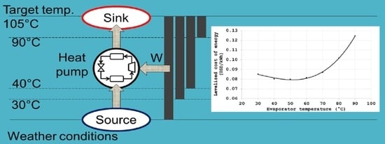
The heat pump design must guarantee the heat requirement at the target temperature in industrial applications. One of the main advantages of the heat pump is that it uses low-temperature heat and generates high-temperature heat through working on the compressor. The temperature in the evaporator can be as low as the ambient temperature, while the maximum temperature in the condenser depends on the working fluid.
The behavior of the power consumption in the compressor is exponential, so the economic evaluation associated with the power consumption is a variable that defines the sustainability of the heat pump. One of the main challenges to solve is the power consumption in the compressor, which grows exponentially when the temperature in the evaporator is reduced. The challenge, therefore, is to find the conditions with the lowest cost of the compressor and the highest temperature that it is possible to reach in the condenser, making its design and construction feasible.
In present work was designed a system of a heat pump device powered with solar thermal energy. The proposed system was thermally and economically evaluated to guarantee the supply of the heat load at the temperature level required by the process under different conditions and operating temperatures in the evaporator. The range of operating temperatures in the evaporator is a function of the variability of the punctual, daily, and seasonal irradiance that allows finding the conditions with the lowest energy cost and evaluating how the cost of the proposed system changes with variations in the levels of irradiance and therefore the temperature of the solar thermal energy that feeds the evaporator. The proposed system presents a payback time of 3.57 years for the dairy industry and 1.8 for the 2G bioethanol production industry.
2. The Proposal: System Low-Temperature Heat Source-Heat Pump
A heat pump is a heat engine that operates in four thermodynamic processes.
Figure 2 represents the thermodynamic states that are reached in each stage; point 1 is the entrance to the evaporator, point 2 is the entrance to the compressor, point 3 is the entrance to the condenser, and finally, point 4 is the inlet to the expansion valve.
Based on the established thermodynamic states, the operating conditions of the heat pump are determined in each of its components, which are: the power of the compressor,
, heat load of the condenser,
, heat load, the expansion valve, and evaporator heat load,
. It is necessary to determine the mass flow of the working fluid,
, with which the system works, and it can be obtained by means of Equation (1):
where
corresponds to the heat load of the condenser and must provide the process in kW. The enthalpy difference corresponds to the condensation process at constant pressure. The enthalpy at point 3 corresponds to the intersection of the entropy line of 1.7 kJ/kg K and the temperature of 105 °C with a value of
. Considering 5 °C of subcooling in the condenser at the same condensing pressure, the next point corresponds to the intersection of such pressure with the 95 °C temperature line, obtaining
. Once the mass flow of the refrigerant is determined, the heat load of the evaporator is obtained due to the expansion process being carried out at constant enthalpy,
. To determine the value of
, the level of superheating necessary to reach the entropy line of 1.7 kJ/kg K must be considered since the next step is the compression process, which is carried out isentropically.
Figure 2 (see lines above) shows the proposed working isotherms with their respective superheating temperature, where
is the inlet temperature to the evaporator or the working isotherm, while
is the temperature at which the refrigerant must be superheated. With these conditions, it is possible to determine the enthalpy at the outlet of the evaporator,
, where the required heat load in the evaporator,
, is given by Equation (2).
the work in the compressor,
is calculated with Equation (3).
where,
, corresponds to the real enthalpy difference, that is, considering a non-isentropic process. From the isentropic efficiency of a compressor expressed in Equation (4), we can obtain the value
.
For a real compressor, the isentropic efficiency is between 80 and 95% [
24]; in the case study, a value of 85% efficiency is proposed to determine the power consumed by the compressor.
The coefficient of performance, COP, of the heat pump is defined as the ratio between the power (kW) that is extracted from the heat pump as cooling or heating and the power (kW) that is supplied to the compressor. Equation (5) shows this relationship.
The working fluid used in the design of the heat pump is the trans-1,3,3,3-tetrafluoropropene compound known as R-1234ze (E). This refrigerant meets the thermodynamic, operational, and environmental properties (GWP < 1 and ODP = 0) to be used safely.
For there to be heat exchange between the current coming from the heat source and the refrigerant, a difference of 10 °C between the currents was proposed. Therefore, the outlet temperature of the heat source is 10 °C higher than the refrigerant temperature leaving the evaporator.
The storage volume can be calculated from Equations (6) and (7) [
25]:
where
, is the process operating time, the density of the water was taken as an average of the values reported between 19 and 100 °C (
), ΔT corresponds to the temperature difference of the stored water, which is the subtraction between the outlet temperature of the low-temperature heat source (
) and the water temperature at average ambient conditions (
). The difference in costs associated with the difference in evaporator and condenser temperatures is mainly due to the power consumed by the compressor. The cost associated with the compressor,
is a function of the power and is determined by Equation (8), [
26].
where
corresponds to the power consumed by the compressor in horsepower. Then, the costs of the proposed system for each evaporator temperature were determined. The cost evaluation considers only the cost of capital. In the estimation of the capital investment of the energy system, the components considered are the cost of the hot water storage system,
, [
27], the cost of the heat pump,
, and heat pump components (heat exchangers costs,
[
28], and compressor,
, see Equation (8). Where,
is the storage volume in m
3,
is the power compressor in hp, and
is the heat exchanger area in m
2.
The levelized cost of energy, LCOE, was used for the evaluation of the profitability of the energy system. The LCOE relates the cost for each unit of energy produced, which means USD per kWh, and is defined by Equation (9).
The levelized cost evaluates the product of the capital recovery factor, CRF, investment costs of the system, , and the costs of auxiliary services, , with respect to the production of energy by the system, . The costs were annualized for a period of 25 years, which corresponds to the useful life of an industrial plant. In the economic estimate, an interest rate of 8% is considered. Finally, the simple payback of the heat pump and energy storage system, SPB, is estimated, and the savings from burning natural gas are considered (reported for 2022 in 0.293 USD/kWh).
2.1. Case Study 1: Dairy Production
As one-of-two case studies, the dairy production process is analyzed. This plant works seven days a week, 300 days a year. The pasteurization of 20,000 L of milk per day requires a heat load of 880 kW for 5 continuous hours at a temperature of 85 °C. The current process is supplied by burning natural gas in a fire tube boiler that reports an efficiency of 92%.
Figure 3 shows the proposed energy system, a low-temperature heat source joined to a hot water storage system and joined in heating pump, with the purpose of reducing the environmental impact of the industrial process. The heat source supplies the heat load of the evaporator of the heat pump at a low temperature and, by means of the operation of the heat pump, reaches a high temperature in the condenser and supplies the heat load of the process.
2.2. Case Study 2: 2G Anhydrous Bioethanol Production
The second case study is the production process of 2G anhydrous bioethanol from agave bagasse. There, 20,454 kg/year of this biofuel is obtained. This plant operates 16 hours a day for 350 days a year. The thermal energy demand is 636.79 kW at a temperature of 105 °C, which is supplied by a boiler that works with natural gas.
4. Discussion
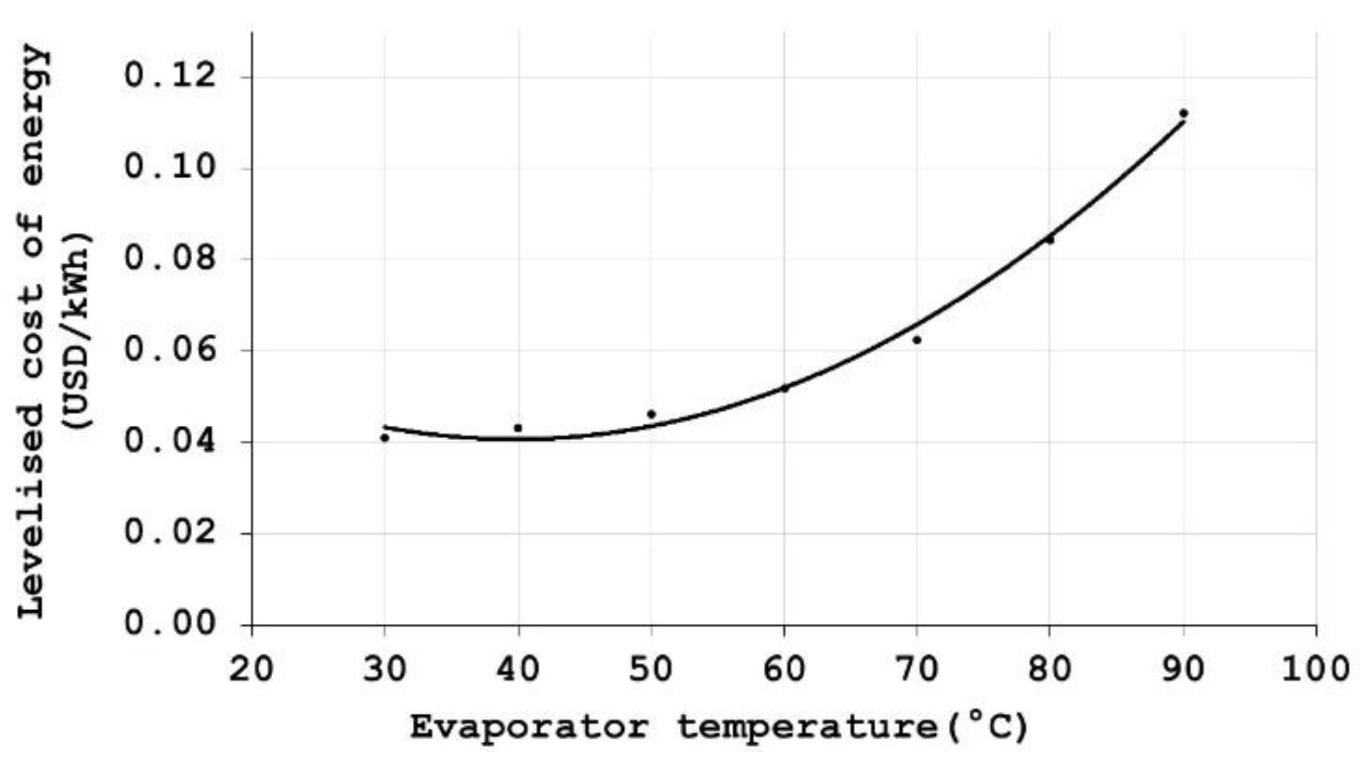
The range of temperatures evaluated allowed us to consider the lowest levels of irradiance that occur during the year and how this irradiance modifies the outlet temperature of hot water. This temperature determines the evaporator temperature. The compressor work is determined by source and sink, and the compressor cost is the component that most impacts the total cost heat pump. Heat pump cost plus solar thermal energy cost is the cost of the proposed system. The proposed system that presents the highest cost is when a heat load of 610.64 kW must be supplied at a temperature of 30 °C in the evaporator of the heat pump with low irradiance levels.
The proposed system has two main components, the heat pump, and low-temperature heat source, which supply the heat load to the evaporator. There are some variables like evaporator temperature, low-temperature heat source, refrigerant, total levelized cost of the system, coefficient of performance of the heat pump, and compressor cost. All these variables determine the minimum total energy cost of the system. The cost of the storage system behaves like an exponential function when the temperature of the evaporator increases from 30 to 90 °C. The COP presents the same behavior, exponential, increasing when the evaporator temperature increases. It is important to point out that the cost of the low-temperature heat source varies with the evaporator temperature like quadratic function; attending the methodology proposed by Martínez-Rodríguez et al., 2019 [
4], means that levelized cost grows up with evaporator temperature. The heat pump assisted with a low-temperature heat source that presents the lowest cost to supply a heat load in the evaporator of 700.4 kW with an operating temperature of 50 °C.
The case studies present differences in heat flux, operation time, and target temperature. The dairy case study requires a heat load of 880 kW for 5 h at a temperature of 85 °C. Meanwhile, the 2G anhydrous bioethanol production process operates for 16 hours and requires a heat load of 636.79 kW at a temperature of 105 °C. The heat flow delivered by the heat pump defines its size and its cost.
There is a region (of design) in which the levelized cost of energy is lower for both case studies, which ranges between 30 and 50 °C of evaporator temperature. The lowest temperature level corresponds to the low levels that occur during the year. The total cost of energy has two main components, the cost of the low-temperature energy source and the cost of the heat pump. The cost of the energy source increases depending on the temperature and the heat load required by the heat pump. At the same time, the cost of the heat pump decreases, as does the work on the compressor as the evaporator temperature increases. Depending on the case study, the contribution of the main components of the proposed system will define the shape of the resulting function. At temperatures above 80 °C in the evaporator, the compressor power becomes asymptotic, and the cost of the proposed system skyrockets.
For the same range of evaporator temperatures (60 to 90 °C), the levelized cost of energy is significantly higher for the 2G bioethanol process compared to the dairy process due to the target temperature of each process and the operation time.
The temperature in the evaporator is the variable that most impacts on the cost of the heat pump assisted with solar thermal energy. As the temperature in the evaporator increases, the cost of the heat pump decreases, and the cost of solar thermal energy generally increases. The two case studies present similar cost behaviors as a function of evaporator temperature with different operating conditions. The main variable that affects the operation of the heat pump is the temperature of the refrigerant evaporator since this directly influences the work of the compressor required to raise its temperature. With low evaporator temperatures, the work of the compressor is greater, and the COP of the heat pump is lower. By having evaporator temperatures closer to the refrigerant condenser temperatures, the work required is less and the COP increases, and the heat demand on the evaporator increases.


 ,
, 


