Article

Three Voltage Vector Duty Cycle Optimization Strategy of the Permanent Magnet Synchronous Motor Driving System for New Energy Electric Vehicles Based on Finite Set Model Predictive Control

1
Department of Electrical and Electronic Engineering, Faculty of Engineering, Universiti Putra Malaysia, Serdang 43400, Selangor, Malaysia
2
Advanced Lightning, Power and Energy Research Centre (ALPER), Faculty of Engineering, Universiti Putra Malaysia, Serdang 43400, Selangor, Malaysia
3
Infineon Technologies China Co., Ltd., Xi’an 710077, China
4
Institute of Nuclear and New Energy Technology, Tsinghua University, Beijing 100084, China
5
School of Electronic Engineering, Xi’an University of Posts and Telecommunications, Xi’an 710121, China
6
School of Control Science and Engineering, Shandong University, Jinan 250061, China
*
Author to whom correspondence should be addressed.
Energies 2023, 16(6), 2684; https://doi.org/10.3390/en16062684
Submission received: 27 October 2022 / Revised: 14 November 2022 / Accepted: 16 November 2022 / Published: 13 March 2023
(This article belongs to the Special Issue Modeling and Optimization Control of Power Battery)

Abstract

:
Faced with the increasingly serious energy crisis and environmental pollution problems, traditional internal combustion engine vehicles are receiving more and more resistance, which has rapidly promoted the development of new energy electric vehicles. Permanent magnet synchronous motors are widely used in new energy electric vehicles and in other fields because of their simple structure, light weight, small size, and high power density. With the continuous advancement of production technology, the requirements of accuracy, rapidity, and stability in permanent magnet synchronous motor systems have gradually increased. Among many advanced control technologies, this paper proposes an optimized model predictive torque control strategy based on voltage vector expansion. This strategy involves the construction of a reference stator flux linkage vector based on the analytical relationship between electromagnetic torque, reference stator flux linkage amplitude, and rotor flux linkage and the transfer of the separate control of electromagnetic torque and flux linkage amplitude into flux linkage vector control. At the same time, the optimal duty cycle corresponding to the two adjacent extended voltage vectors and the zero vector is calculated according to geometric relationships so as to realize the three voltage vector duty cycle optimization control. Experimental results show the effectiveness and superiority of the proposed strategy.

1. Introduction

Nowadays, the energy crisis and environmental pollution have become major challenges to be resolved all over the world [1,2,3,4]. The gradual depletion of traditional fossil energy has placed great pressure on the environment in the process of utilization, such that traditional oil-fueled vehicles are being increasingly replaced by new energy electric vehicles (NEEVs) [5,6,7,8]. With their natural advantages and properties, NEEVs have been greeted with an avalanche of publicity due to their being more environmentally friendly, having remarkable energy-resource efficiency and zero carbon emissions and zero wastage [9,10,11]. Driving motors are the core components of the electric control drive systems in NEEVs. High-performance driving motors can significantly improve durability and mileage. The permanent magnet synchronous motor (PMSM) has become the primary choice because of its high control accuracy, wide speed range, high density, smooth electromagnetic torque ripples, and low noise levels. However, the PMSM also faces many challenges under various complex working conditions. Therefore, efforts to optimize the control methodology of the PMSM have real practical value and significance [12].
The PMSM was invented by Barlow in 1831. It uses permanent magnet excitation, which has excellent excitation performance and can generate a permanent magnetic field after magnetization. The PMSM has the advantages of a simple structure, reliable operation of the AC motor, and good speed regulation performance of the DC motor. Excitation winding, electric brush, commutator, and collector rings are omitted. The main components of the PMSM are the stator and the rotor. The stator consists of a silicon steel sheet, a motor shell, an end cover, and three-phase symmetrical distribution windings. The rotator is composed of permanent magnetic steel, a yoke, and a rotor iron core. The PMSM creates a three-phase alternating power source with three phase inverters, which produces a space rotating magnetic field inside the stator winding at an angular velocity of electrical frequency. When the PMSM interacts with the permanent magnet of the rotator, it generates electromagnetic torque to drive the motor rotation [13].
The outstanding characteristics of the PMSM can be summarized as follows:
  • A simple structure with a small volume that is lightweight and has low noise levels;
  • A permanent magnet is used to provide excitation, with small excitation losses and high operational efficiency;
  • Low rotating inertia, high starting electromagnetic torque, and excellent static and dynamic response performance.
However, the PMSM is a complex object with multiple variables, strongly coupled, a seriously non-linear function, and unpredictable parameters. What is more, it is subject to many uncertainties, external load interferes, and unmodeled object and non-linear dynamics [14]. In the design process for the PMSM, the traditional control methodology is characterized by a simple structure and stability [15]. In addition, given the low in-control precision and sensitivity to mathematical modeling, it is easily affected by unknown disturbances and unmatched parameter circumstances, and, unfortunately, it is unable to cope with the requirements of high-performance transmission control and reduction of all possible damage due to system failure [16].
For several decades, with the development of chip designs and manufacturing technologies, some computationally intensive and complex control methodologies have been applied in microcontrollers. Model predictive control (MPC) has been gradually proposed, studied, and developed by various researchers. A large number of MPC methods have been applied widely in motor drive systems due to their expected dynamic responses, feasible multi-objective optimization, and stronger nonlinear control performance [17,18]. MPC is also considered a substitute to field-oriented control (FOC) and direct torque control (DTC). The main features of MPC are the prediction of future changes in control variables (such as current, electromagnetic torque, and flux linkage) and the ability of the controller to determine the optimal operating mode based on a predefined cost function [19]. The voltage vector selected for MPC is more accurate and effective than DTC. Compared with FOC, MPC can achieve faster dynamic response.
Due to the differences in voltage-vector control sets, MPC can be divided into continuous control set model predictive control (CCS-MPC) and finite control set model predictive control (FCS-MPC). In the CCS-MPC, the controller output is a continuous reference signal, which is converted into an appropriate action using a modulator. FCS-MPC makes use of the limited switching states in three-phase inverters to enumerate the corresponding conditions in all switching states. Once the optimal switching states are found, the corresponding driving signals are outputted immediately and held fixed during each switching cycle. FCS-MPC controls the electromagnetic torque, stator flux linkage, and stator current at the same time. In addition, because of the different optimal control objectives, there are two main categories of important branches for FCS-MPC in the motor field: finite control set model predictive torque control (FCS-MPTC) and finite control set model predictive current control (FCS-MPCC) [20,21,22,23,24].
As an efficient advanced process control strategy that is able to deal well with many different kinds of engineering constraints explicitly, MPC has been studied by many scholars for a long time, and many different subjects have made their contributions to different aspects [25,26,27,28,29,30,31,32,33,34,35,36,37,38]: a prediction-error-driven position estimation method based on current prediction errors of finite control set model predictive control for the position-sensorless control of a PMSM [25]; a modulated model predictive current controller for PMSM [26]; the use of disturbance observations to improve model predictive control [27,28,29]; model predictive control and iterative learning control to not only speed up system response time but also effectively reduce speed ripples [30]; switching sequence model predictive direct torque control for IPMSMs for NEEVs in switch open-circuit fault-tolerant mode [31]; a cascaded variable rate sliding mode speed controller for model predictive current control [32]; a cascade-free modulated predictive direct speed control scheme for PMSM drives to further enhance steady-state performance on the basis of a simple control structure [33]; better quality currents and electromagnetic torque ripples in dual-vector model predictive current control [34]; ultra-local model-free predictive current control, which does not involve any motor parameters based on nonlinear disturbance compensation [35]; a data-driven, real-time-capable, recursive least-squares estimation method for the current control of a PMSM [36]; a discrete duty-cycle control strategy to reduce both the electromagnetic torque and flux ripples that appear in model predictive torque control [37]; and discrete space vector modulation to achieve flux-linkage and electromagnetic torque ripple reduction in finite set model predictive torque control [38].
In order to eliminate the weight coefficient of the cost function in traditional MPTC, this paper proposes an expanded three voltage vector duty cycle optimization model predictive torque control strategy. In order to verify the practicability of the proposed method, a PMSM platform based on Infineon’s DSP + FPGA has been developed. The experimental results show that the recommended solution could effectively further enhance and improve control-system performance and energy efficiency.
The rest of the paper is organized as follows. The principles and a mathematical description of model predictive control for the PMSM are detailed in Section 2. Section 3 provides the reference voltage vector calculation for a PMSM driving system. In Section 4, the three voltage vector duty cycle optimization strategy based on finite set model predictive control is elaborated. In Section 5, the experimental situations are described and an analysis of the results is given. Finally, the conclusions and future work are summarized in Section 6.

2. The Principles and Mathematical Description of Model Predictive Control for the PMSM

According to the different installation positions of the permanent magnets on the rotor, there are two general types of PMSM, as shown in Figure 1: the surface permanent magnet synchronous motor (SPMSM) and the interior permanent magnet synchronous motor (IPMSM). The SPMSM is also known as the non-salient pole synchronous motor. The permanent magnet is installed on the rotor surface and the magnetic circuit is basically symmetrical in the quadrature and direct axes, so that the d and q inductances are equal, which makes it easy to achieve an optimal design. The IPMSM is also known as the salient pole synchronous motor. The permanent magnet is embedded in the rotor iron core. With a high power density and an asymmetric rotor magnetic circuit, it will also generate additional reluctance electromagnetic torque. It has a wide field weakening space and is more suitable for high-speed motor operation circumstances. Due to different rotor structures, the magnetic circuits are not the same, and the performances of the SPMSM and the IPMSM are also unlike. Compared with the SPMSM, the IPMSM has higher efficiency, greater cogging electromagnetic torque ripples, and lower losses at high temperatures, but there are many high-frequency harmonics which cause eddy current losses in the stator and the rotor. The SPMSM can also output power supply and electromagnetic torque similar to the IPMSM, with similar high flux linkage density conditions, but the iron loss is high under light loads. In the non-weakening field mode, the power factor of the SPMSM is generally higher than that of the IPMSM. In this paper, the SPMSM is selected as the controlled object.
A, B, C three-phase symmetrical distribution windings are installed on the stator of the PMSM. The rotating rotor generates a space magnetic field, and the stator and rotor are coupled through the air-gap magnetic field. The electromagnetic relationship inside the PMSM is very complex, and the following assumptions are usually made before analyzing the PMSM’s mathematical predictive model:
  • Ignore the iron core magnetic resistance of stator and rotor, regardless of eddy current and hysteresis loss;
  • Permanent magnet material conductivity is zero, and the internal permeability of the permanent magnet is the same as that of the air;
  • The distributions of excitation and armature-reaction magnetic fields in air gaps are sinusoidal waves;
  • The undamped winding of the rotor, armature resistance, and inductance of each phase winding in the stator are equal;
  • In steady-state operation, the induced electromotive force waveforms generated in each phase winding are sinusoidal waves.
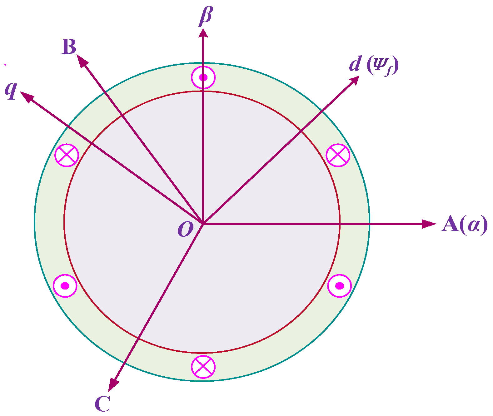
When studying the control strategy for the PMSM, three coordinate systems are usually applied, as shown in Figure 2:
  • A, B, and C represent a three-phase static coordinate system, which has three axes, A, B, and C, in the three-phase windings of the stator at angles of 120° to each other in space;
  • α and β represent a static coordinate system, a two-phase static coordinate system, where the α -axis is coincident with the A-axis in the three-phase static coordinate system, while the β -axis advance counterclockwise electric angles are at 90° to the α -axis;
  • d and q represent a rotating coordinate system, which is a two-phase synchronous rotating coordinate system, in which the direction of the rotor flux linkage vector (the permanent magnet chain) is along the d-axis and rotates synchronously with the rotor, while the q-axis advances the d-axis electric angles 90° counterclockwise.
As a model predictive optimization control strategy, MPC has three main components: a prediction model, rolling optimization, and feedback correction. First, according to the discrete mathematical model of the controlled object, the state quantity in the future time is predicted at the current moment of the system. Then, the predicted value and given value are brought into the cost function, and, using cost function optimization, the optimal combination of switches is selected to act on the controlled object and finally update the system state. MPC can also be referred to as receding horizon control because an MPC system continuously detects new values and repeats such processes in each control cycle. A block diagram of the model predictive control algorithm is shown in Figure 3.
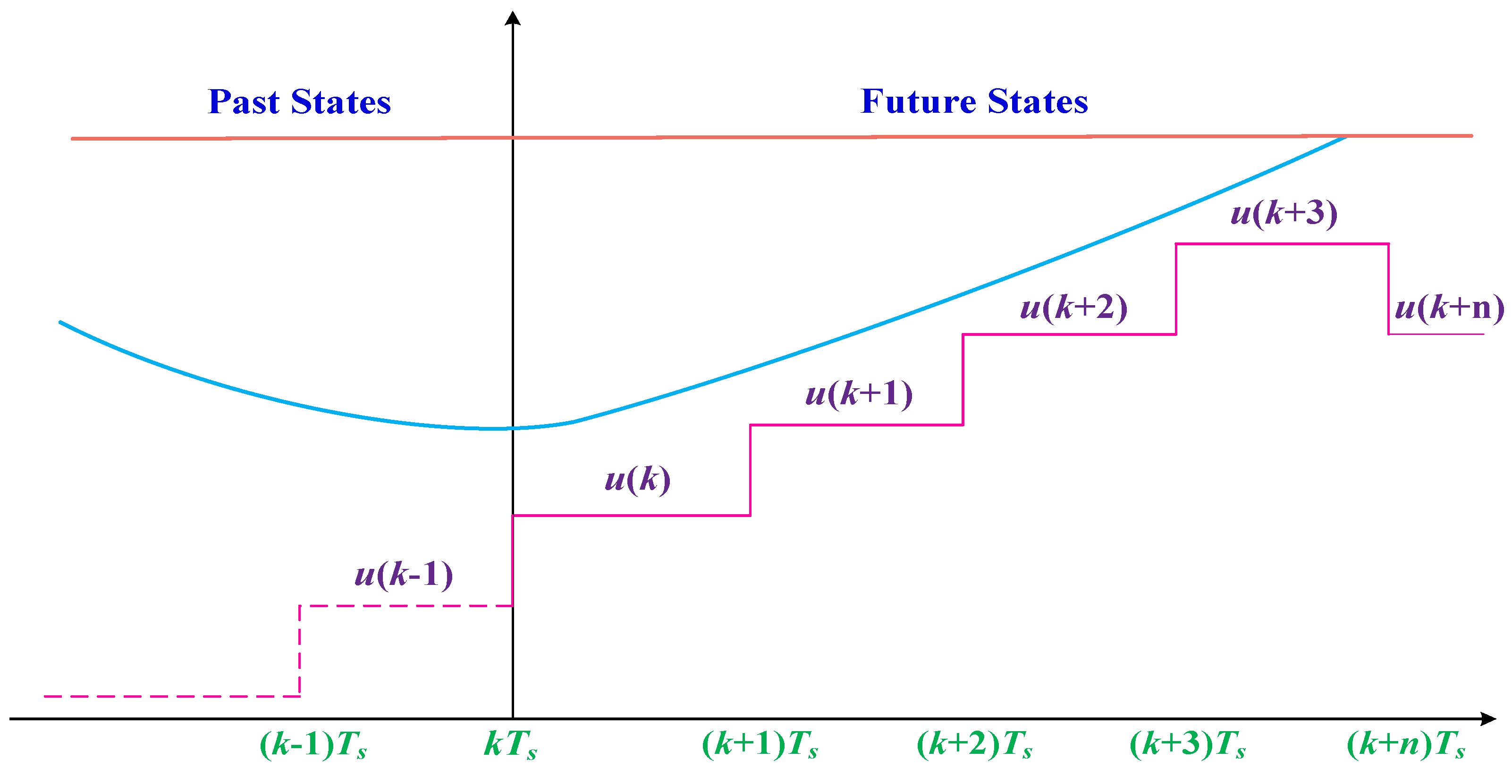
Figure 4 shows the working principle of MPC. The future state of the system in the predetermined time period k + N is obtained by using the sampled measured values and the effective data before the time k to predict the system’s mathematical model. According to the principle of minimizing the cost function, the operation modes are optimally sequenced, and the first operation mode in the sequence is applied to the system to achieve optimal control. Due to the system collecting relevant data in each control cycle, the whole prediction process is executed, and rolling optimization is continuously carried out to ensure accurate outputs.
MPC has several advantages:
  • It can be applied to a multi-variable control system;
  • Constraints are used to optimize the controller, which is simple and easy to design;
  • It has high flexibility to optimize solutions for specific application areas.
In order to apply MPC in the motor driving systems of NEEVs, it is necessary to build a mathematical description of the prediction model for the PMSM. A discrete time model needs to include all of the control variables and predict them. The forward Euler formula can be expressed as:
d x d t = x ( K + 1 ) x ( k ) T s
where T s is the sampling period, K is the current time, and x ( K + 1 ) is the predictive value at the next time.
In the d and q rotating coordinate system, discretizing the voltage expressions for the PMSM by the forward Euler formula, the current prediction model can be written as follows:
{ i d ( K + 1 ) = i d ( k ) + 1 L d [ R s i d ( k ) + ω e L q i d ( k ) + u d ( k ) ] T s i q ( K + 1 ) = i q ( k ) + 1 L q [ R s i q ( k ) + ω e L d i q ( k ) + u q ( k ) ω e Ψ f ] T s
Discretizing the flux linkage expressions of the PMSM by the forward Euler formula, the flux linkage prediction models are:
{ Ψ d ( K + 1 ) = T s [ u d ( k ) R s i d ( k ) + ω e Ψ q ( k ) ] + ω e Ψ d ( k ) Ψ q ( K + 1 ) = T s [ u q ( k ) R s i q ( k ) + ω e Ψ d ( k ) ] + ω e Ψ q ( k )
Substituting Equations (2) and (3) for electromagnetic torque expressions yields:
{ T e ( K + 1 ) = 3 2 p i q ( k + 1 ) [ i d ( k + 1 ) ( L d L q ) + Ψ f ] }
Therefore, Equations (2)–(4) are the important components and theoretical fundaments of the mathematical model for predictive control with the PMSM.

3. Reference Voltage Vector Calculation

In the traditional MPTC strategy, by predicting the electromagnetic torque and stator flux linkage at the next moment, using a cost function to minimize error with the reference value, the optimal basic voltage vector is selected from the basic voltage vector to act on the system to realize the target for the reference value of electromagnetic torque and stator flux linkage tracking. The novel MPTC method proposed in this paper uses the obtained reference voltage vector to realize multi vector duty cycle control through the calculation of the optimal duty cycle.
There are different ways to obtain the reference voltage vector in traditional MPTC. In this paper, the reference voltage vector is calculated based on the deadbeat control principle of the stator flux linkage vector by converting the amplitude of electromagnetic torque and stator flux linkage into the magnetic chain vector control. What is even more meaningful is that the control objectives are able to track the reference magnetic chain vector.
In a two-phase synchronous rotating coordinate system, according to the stator flux linkage equations, the quadrature axis current i q can be expressed by the stator flux linkage amplitude | Ψ s | and load angle δ as:
i q = | Ψ s | sin δ L s
In order to satisfy the zero-error condition, following the reference values for the electromagnetic torque and the magnetic chain, the relationships among the reference electromagnetic torque T e * , the reference stator flux linkage amplitude | Ψ s * | , and reference load angle δ * should meet:
δ * = arcsin ( 2 T e * L s 3 p Ψ f | Ψ s * | )
where the reference electromagnetic torque T e * is obtained through the output of the PI controller adopted in the speed loop and the reference stator flux linkage amplitude | Ψ s * | is obtained using the maximum electromagnetic torque current ratio through the MTPA algorithm. For the SPMSM, combining i d = 0 with the electromagnetic torque equations, the reference stator flux linkage amplitude | Ψ s * | can be expressed as:
| Ψ s * | = ( L s i d + Ψ f ) 2 + ( L s i d ) 2 = Ψ f 2 + ( L s 2 T e * 3 p Ψ f ) 2
According to Equations (6) and (7), which convert the amplitude of the electromagnetic torque and the magnetic chain into the stator flux linkage vector control, the relationships among the reference stator flux linkage vector Ψ s * , the reference electromagnetic torque T e * , and the reference stator flux linkage amplitude | Ψ s * | are:
Ψ s * = | Ψ s * | e j θ s = | Ψ s * | e [ j ( δ * + θ e ) ]
where δ * is the reference load angle. When there is a certain deviation between the actual stator flux linkage vector Ψ s and the reference stator flux linkage Ψ s * , the relationships between them can be expressed as:
Ψ s * = Ψ s + Δ Ψ s e r r = Ψ s + Δ Ψ α s e r r + j Δ Ψ β s e r r
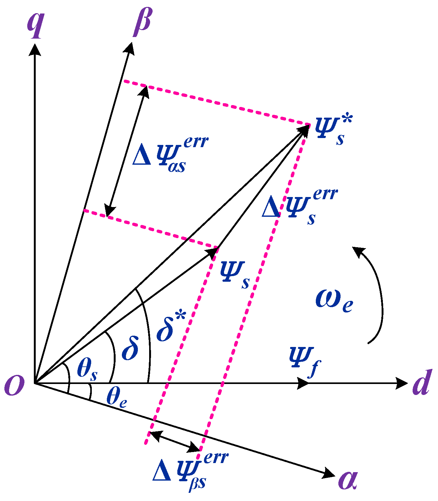
where Δ Ψ s e r r is the error of the stator flux linkage vector and Δ Ψ α s e r r and Δ Ψ β s e r r are the projections of Δ Ψ s e r r on the α - β -axis. When Δ Ψ s e r r is 0, the reference and actual stator flux linkage vectors are same, which means that the actual amplitude of electromagnetic torque and stator flux linkage are equal to the given reference values, and thus zero-error tracking control is implemented. Figure 5 shows a schematic diagram of stator flux linkage vector error.
In non-ideal conditions, the motor system experiences a little delay in the calculation and application of the control algorithm, so one-shot delay time compensation is required, and the error between the stator flux linkage vector Ψ s ( k + 2 ) and the reference stator flux linkage Ψ s * should be zero at ( k + 2 ) T s . Derived from Figure 1, the relationship between the reference stator flux linkage phase angle θ s * and the load angle δ * is:
θ s * = θ s ( k + 2 ) = θ e ( k + 2 ) + δ * = θ e ( k + 2 ) + arcsin ( 2 T e * L s 3 p Ψ f | Ψ s * | )
where θ s is the stator flux linkage phase angle and θ e is the rotor flux linkage phase angle.
Given the realization of one-shot delay time compensation, it is necessary to predict the stator current i s ( k + 1 ) at ( k + 1 ) T s according to the stator current i s k at k T s . According to the stator voltage equations for the SPMSM on the α - β -axis, the stator flux-linkage vector Ψ s ( k + 1 ) is first-order Euler-discretized at ( k + 1 ) T s :
Ψ s ( k + 1 ) = Ψ s k + T s [ u s ( k ) R s i s ( k ) ]
Substituting the stator current i s ( k + 1 ) obtained by the delay time compensation into the flux linkage equation, the rotor flux linkage vector Ψ f ( k + 1 ) at ( k + 1 ) T s can be shown as:
Ψ f ( k + 1 ) = Ψ s ( k + 1 ) L s i s ( k + 1 )
On the basis of one-shot delay time compensation, the stator flux linkage vector Ψ s ( k + 1 ) , the stator voltage vector u s ( k + 1 ) , and the stator current i s ( k + 1 ) at ( k + 1 ) T s are used to predict the stator flux linkage vector Ψ s ( k + 2 ) at ( k + 2 ) T s :
Ψ s ( k + 2 ) = Ψ s ( k + 1 ) + T s [ u s ( k + 1 ) R s i s ( k + 1 ) ]
Since the electromagnetic response of the SPMSM is much faster than the mechanical response, it can be considered that the motor speeds at k T s and ( k + 1 ) T s are approximately equal to ω r ( k ) . Therefore, the phase angle of the rotator flux linkage vector at ( k + 2 ) T s is:
θ e ( k + 2 ) = θ e ( k + 1 ) + ω e ( k ) T s
According to Equations (10), (13) and (14), the reference value for the stator voltage vector u s * is:
u s * ( k + 1 ) = Ψ s * Ψ s ( k + 1 ) + T s R s i s ( k + 1 ) T s
Derived from Equation (15), when the stator voltage reference vector Ψ s * ( k + 1 ) is applied at ( k + 1 ) T s , the actual Ψ s and reference Ψ s * of the stator flux linkage vectors are the same, which means that the actual amplitudes of the electromagnetic torque and the stator flux linkage do not deviate from their respective reference values.

4. Three Voltage Vector Duty Cycle Optimization

4.1. Alternative Voltage Vector Extension

In traditional MPTC, eight basic voltage vectors generated by a three-phase inverter are directly used as inputs to the MPTC controller to predict the current, electromagnetic torque, and flux linkage. Rolling optimization of the prediction results is carried out according to the cost function, so that the voltage vector with the smallest cost function acts on the motor system. Since the selection of voltage vectors is limited to the eight basic voltage vectors, they usually have high electromagnetic torque and flux linkage pulsations. In addition, the traditional MPTC needs to optimize the prediction of each voltage vector in a control cycle, which increases the computational burden.
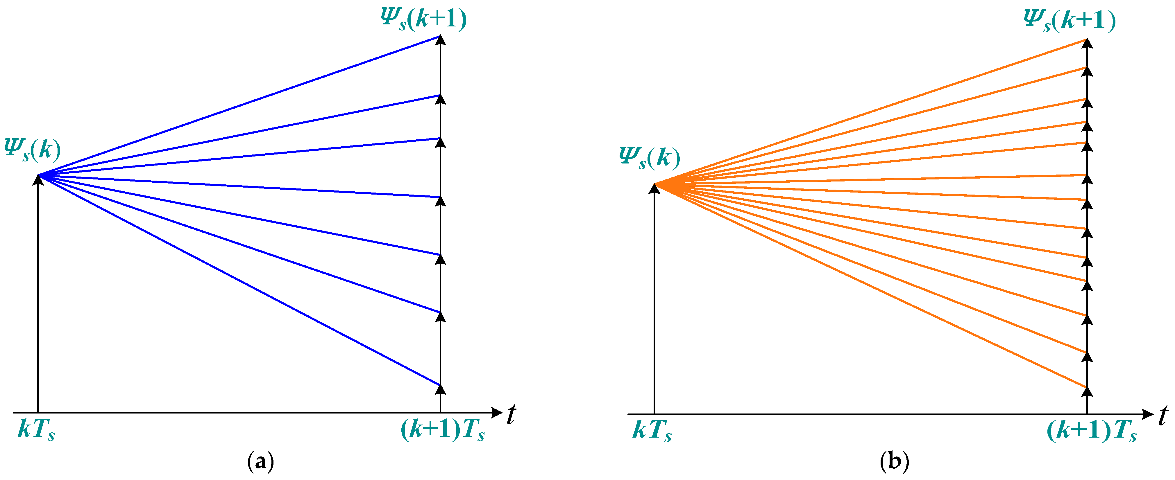
To improve the selection accuracy, an improved finite voltage vector control set is adopted based on the traditional eight voltage vectors. At the same time, in order to make full use of the flux linkage vector control algorithm, the traditional finite control set is optimized to allow more choice regarding the numbers and phase angles of alternative voltage vectors, and a filter for predicting flux linkage vectors can be obtained, which enables the cost function to select a voltage vector with less electromagnetic torque and flux linkage error for more effective control. Furthermore, the electromagnetic torque and flux linkage pulsations can be reduced by increasing the virtual voltage vector. As shown in Figure 6, increase in the different voltage vectors makes the prediction result of the flux linkage vector more refined, and the cost function can select the predictive flux linkage vector with less error.
The specific improvement methods are as follows: the two-level three-phase voltage source inverter can only produce eight switch states, according to the arrangement and combination, corresponding to six non-zero vectors and two zero vectors. In order to improve the accuracy of MPTC, six virtual voltage vectors are added to the traditional basic voltage vectors, which are half of the two adjacent synthesized voltage vectors, and the amplitude is 0.866 times that of the basic voltage vector. In this way, the number of alternative effective voltage vectors is changed from 6 to 12. The extended voltage vector control sets V 1 V 12 are defined in Figure 7.
According to traditional MPTC, fourteen extended voltage vectors are substituted into each control cycle for prediction, and screening through the cost function will greatly increase the algorithm’s calculational burden for the microprocessor, reducing the operating efficiency. Therefore, this paper makes further improvements while extending the voltage vector screening range.
The extended voltage vectors V 1 V 2 are shown in Figure 7. Two adjacent extended basic voltage vectors can be determined at the spatial position of the reference voltage vector in the spatial sector, such that they are close to the actual reference stator flux linkage vector, reducing the number of alternative voltage vectors to two adjacent extended voltage vectors. In traditional MPTC, an optimal voltage vector is selected based on the cost function and acts throughout the whole system. There are only eight basic voltage vectors, and the design of weight coefficients is cumbersome. The optimized FCS-MPTC strategy realizes the duty cycle control of multiple voltage vectors based on the reference voltage vector. Applying multiple voltage vectors to the SPMSM not only eliminates the weight coefficient design process, but also effectively balances the electromagnetic torque and flux linkage pulsations.

4.2. Double Voltage Vector Duty Cycle Control

The extended voltage vector V i and the zero-voltage vector V 0 are combined to form a candidate voltage vector. By adjusting the duty cycle of the extended voltage vector V i , the candidate stator voltage vector u s can be expressed as:
u s = t v i T s V i = d i V i + ( 1 d i ) V 0
where t v i is the action time and d i is the duty cycle.
In order to evaluate the influence of the combined candidate voltage vectors on the stator flux linkage vectors, Equation (17) is used to replace the traditional cost function in MPTC; it only contains the flux linkage vectors and includes no design for the weight factor:
g = | Ψ s * Ψ s ( k + 2 ) |
The new stator flux linkage vector cost function incorporates the actual amplitude of the electromagnetic torque and flux linkage, including the corresponding reference values. The candidate voltage vectors obtained from Equation (15) are used to predict the stator flux linkage vector Ψ s ( k + 2 ) at ( k + 2 ) T s by means of Equation (13), which is carried into Equation (17):
g = | Ψ s * Ψ s ( k + 2 ) | = | Ψ s * + T s R s i s ( k + 1 ) T s d i V i Ψ s ( k + 1 ) | = T s | u s * d i V i |
It can be seen from Equation (18) that in order to minimize the cost function, it is necessary for the difference vector between the candidate voltage vector and the reference voltage vector to be perpendicular to the extended voltage vector when the cost function is the smallest. The optimal duty cycle of the extended voltage vector can be expressed as:
d i o p t = | u s * | cos θ v u | V i | = | Ψ s * Ψ s ( k + 1 ) + T s R s i s ( k + 1 ) | cos θ v u | V i | T s
where d i o p t is the duty cycle of the extended voltage vector and θ v u is the included angle between the extended voltage vector and the reference voltage vector. Bringing the optimal duty cycle derived from Equation (19) into (18) and selecting the extended voltage vector, which minimizes the cost function and the corresponding optimal duty cycle from the two adjacent extended voltage vectors of the reference voltage vector, acts on the system to achieve double-vector control.

4.3. Three Voltage Vector Duty Cycle Control

Based on the reference stator voltage vectors obtained in the double voltage vector duty cycle control above, by filtering out the two adjacent extended voltage vectors to reduce two vector numbers, the duty cycle is introduced with zero vectors to obtain the voltage vectors for different amplitudes. The optimal voltage vector and its duty cycle are selected to act on the motor system by using the new stator flux linkage vector cost function. Therefore, the control precision of the electromagnetic torque and flux linkage is effectively improved. The effects of different voltage vector combinations on the pulsations of the stator flux linkage vectors are shown in Figure 8. It can be seen from Figure 8 that the tracking control of the stator flux vector can be achieved by optimally allocating the duty cycles of the different voltage vectors.
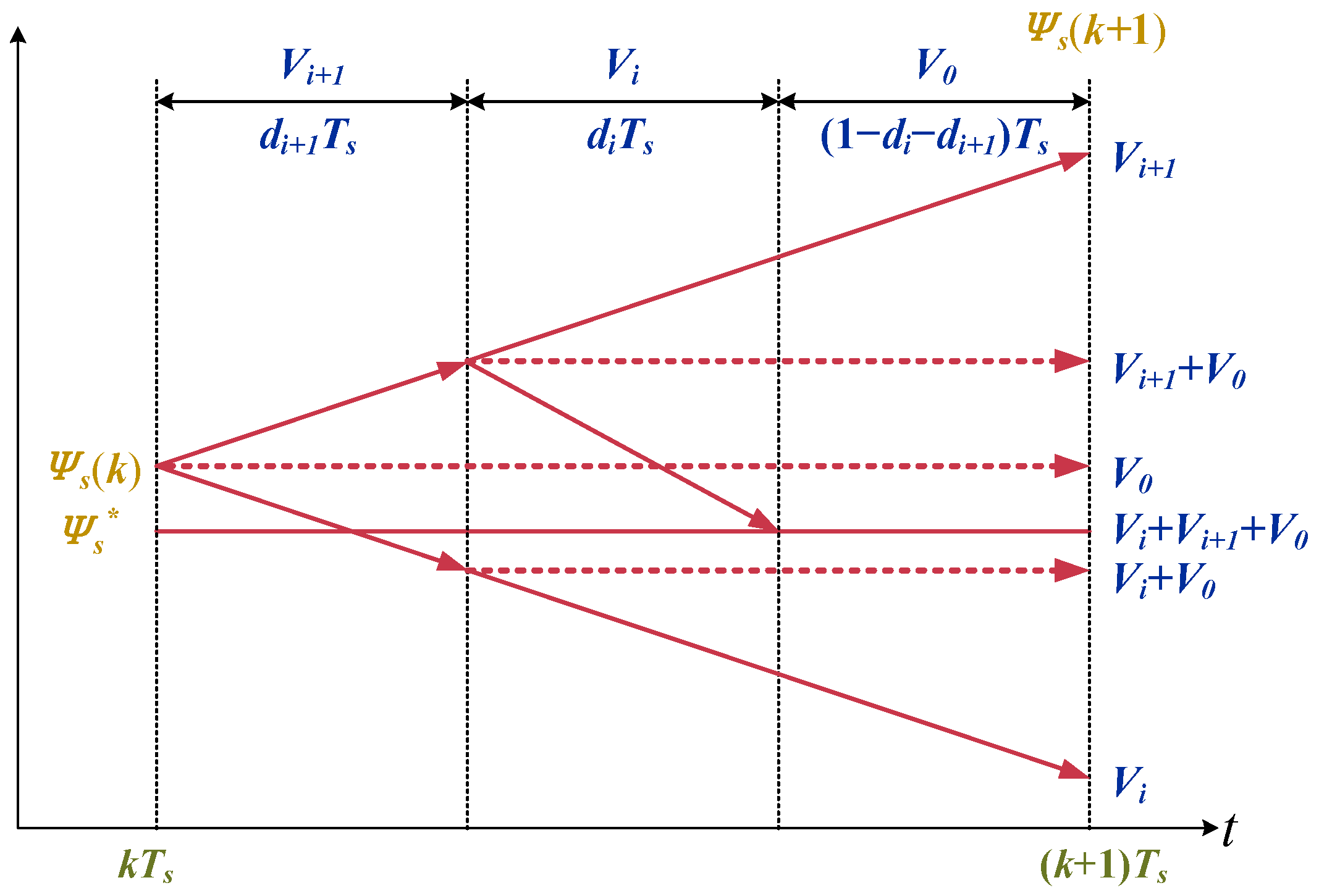
On the basis of the double voltage vector duty cycle control, an additional effective voltage vector is added, that is, two adjacent extended voltage vectors and zero vectors are used to construct a reference voltage vector to realize the duty cycle control of three voltage vectors. By adjusting the operating times of the three voltage vectors in one control cycle, the synthetic candidate voltage vectors are coincident with the reference voltage vectors, thus achieving more accurate control. The principle of using three voltage vectors to synthesize a reference voltage vector is shown in Figure 9.
u s * = d i V i + d i + 1 V i + 1 + ( 1 d i d i + 1 ) V 0
where V i is the extended voltage vector and d i + 1 is duty cycle of V i .
Similarly, in order to evaluate the influence of the combined candidate voltage vectors on the stator flux linkage vectors through three voltage vector duty cycle control, as expressed in Equation (17), the candidate voltage vector obtained from Equation (20) is used to predict the stator flux linkage vector Ψ s ( k + 2 ) at ( k + 2 ) T s by means of Equation (13), which is carried into Equation (18) to obtain:
g = | Ψ s * Ψ s ( k + 2 ) | = | Ψ s * + T s R s i s ( k + 1 ) T s d i V i T s d i + 1 V i + 1 Ψ s ( k + 1 ) | = T s | u s * d i V i d i + 1 V i + 1 |
As can be seen from Figure 9, in order to optimize the cost function of the stator flux linkage vectors, the reference voltage vector and candidate voltage vector of the three voltage vector combination are equal, and the optimal duty cycle of two adjacent extended voltage vectors can be obtained according to the parallelogram vector combination method. Using the triangle sine theorem from geometric relationships:
d i o p t | V i | sin ( π / 6 θ v u ) = d i + 1 o p t | V i + 1 | sin ( θ v u ) = | u s * | sin ( 5 π / 6 )
The optimal duty cycle of two adjacent extended voltage vectors can be derived from Equation (22):
d i o p t = | u s * | sin ( π / 6 θ v u ) | V i | sin ( 5 π / 6 ) = 2 | u s * | sin ( π / 6 θ v u ) | V i |
d i + 1 o p t = | u s * | sin ( θ v u ) | V i + 1 | sin ( 5 π / 6 ) = 2 | u s * | sin ( θ v u ) | V i + 1 |
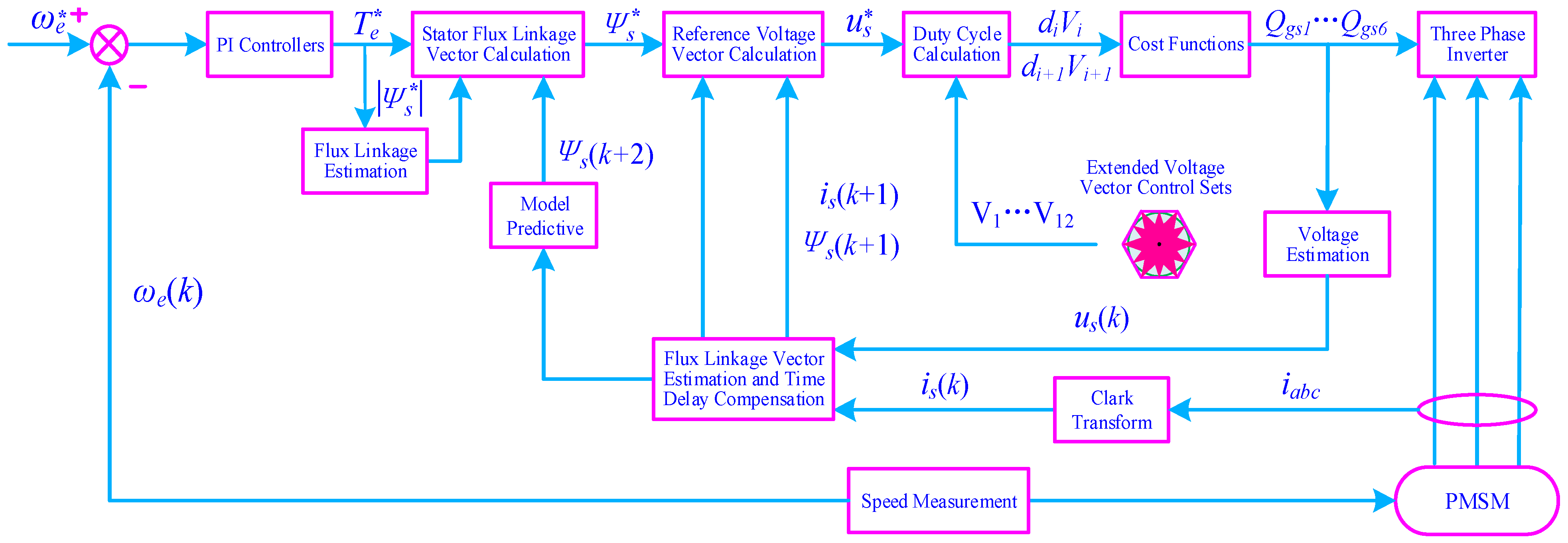
Based on two adjacent extended basic voltage vectors and their corresponding optimal duty cycle, two effective and zero vectors are combined to achieve duty cycle control. The control effectiveness of the combinational voltage vectors with the duty cycle is fully considered, ensuring that the added voltage vector follows the reference voltage vectors and achieves the deadbeat control of the stator flux linkage vector according to its reference value, effectively improving the control accuracy of the electromagnetic torque and stator flux linkage. A block diagram of FCS-MPTC is presented in Figure 10.
The PMSM is driven by a three-phase inverter module, and the reference rotor electrical angular velocity ω e * compares with the rotor electrical angular velocity ω e ( k ) obtained from speed measurement. After the PI controller, the reference electromagnetic torque T e * , the reference stator flux linkage amplitude | Ψ s * | , and the stator flux linkage vector Ψ s ( K + 2 ) are included in a stator flux linkage vector calculation. The reference stator flux linkage vector Ψ s * , the stator flux linkage vector Ψ s ( k + 1 ) , and the stator current vector i s ( k + 1 ) are incorporated into a reference stator voltage vector u s * by flux linkage vector estimation and time-delay compensation (through conversion of the three-phase current i a b c to the stator current vector i s ( k ) of the α and β static coordinate system after Clarke transformation, with the stator voltage vector u s ( k ) from the voltage estimation). Based on the extended voltage vector control sets V 1 V 12 , the drive signals Q g s 1 Q g s 6 are generated from the cost functions d i V i and d i + 1 V i + 1 . All that has been described above is indispensable for the PMSM to work well.

5. Experimental Results

In order to validate the previous analysis and the proposed FCS-MPTC methods experimentally, a three-phase SPMSM drive platform was developed under Infineon’s laboratory conditions to evaluate the effectiveness of the three voltage vector duty cycle optimization strategy based on finite set model predictive control with respect to both steady-state and dynamic performance [39,40].
In the experiment, the magnetic powder brake was used as a load for the SPMSM. The direct current bus supply voltage was 300 V, the control frequency was 10 kHz, and the sampling period was 200 μs. The voltage and current waveforms were directly observed by means of an oscilloscope. The d-q-axis current, rotating speed, electromagnetic torque, and other analog quantities were obtained through the A/D conversion chip. The whole system includes a hardware circuit and a software program: a three-phase inverter module, a drive isolation circuit, a direct current bus voltage sampling circuit, a phase current sampling circuit, a temperature sampling circuit, and an auxiliary power-supply circuit [41,42].
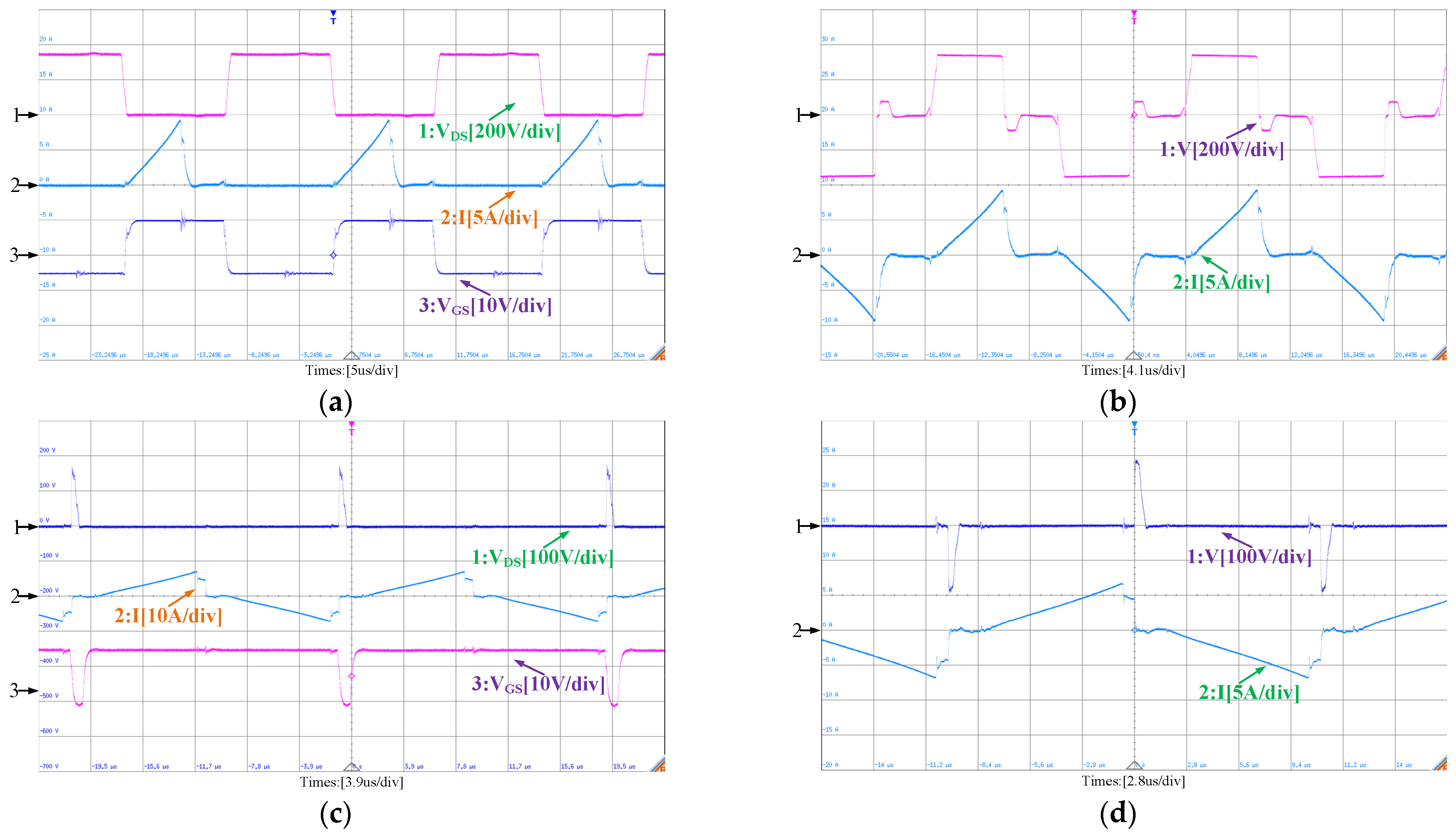
Figure 11a shows the experimental waveforms of the drive voltage 3 : V G S , the voltage across 1 : V D S , and the arm current 2 : I of the three-phase inverter bridge; Figure 11b depicts the primary voltage 1 : V and the current 2 : I of the main transformer. Figure 11c shows the drive voltage 3 : V G S , the voltage across 1 : V D S , and the primary side current 2 : I of the auxiliary switch. The waveform in Figure 11d presents the primary voltage 1 : V and the current 2 : I of the auxiliary transformer.
A. Case 1: Steady-State Performance Under Different Speeds and Loads
In order to study the influence of rotating speed on steady-state performance under different speeds and loads, experimental waveforms for the d-q-axis current at 300 rpm and 500 rpm with 2 N/m load torque can be seen in Figure 12. The d-q-axis current ripple gradually increases with the increase in rotating speed.
B. Case 2: Dynamic Performance Evaluation with Sudden Speeding Up and Down
Figure 13a shows that under 500 rpm with 2 N/m load torque, it accelerates 300 rpm from a steady state of about 100 ms and decelerates from 300 rpm to 200 rpm after 40 ms. The performance following the change in the given speed is better, and the q-axis current can change rapidly. Figure 13b shows the experimental waveform of the current loop following performance. Since the sampling period is 100 μs, the feedback q-axis current is stepped. The given q-axis current starts at 10 A, the actual q-axis current reaches 10 A after three sampling cycles of about 300 μs. It can be seen that the current loop of the three voltage vector duty cycle optimization strategy has better dynamic performance.

6. Conclusions and Future Work

The development and utilization of new energy sources being extremely important due to the global energy crisis and environmental pollution, studies on NEEVs have been attracting extensive attention. PMSMs have been widely used in NEEVs because of their high efficiency, high power density, simple structure, and wide speed range. Recently, efforts have been made to enhance both the dynamic and the steady-state performance of the PMSM control drive system. This paper has proposed an optimized FCS-MPTC method based on voltage vector expansion. This strategy involves the construction of a reference stator flux linkage vector based on the analytical relationship among electromagnetic torque, reference stator flux linkage amplitude, and rotor flux linkage to convert the separate control of electromagnetic torque and flux linkage amplitude into flux linkage vector control, thereby avoiding the cumbersome design of weighting coefficients. On the basis of delay compensation, the reference voltage vector is calculated online according to the deadbeat control principle. Simultaneously, the voltage vector control set is extended, two adjacent voltage vectors are determined according to the spatial position of the reference voltage vector, and the optimal duty cycle corresponding to the two adjacent voltage vectors and the zero vector is calculated according to geometric relationships, so as to realize the three voltage vector duty cycle control. It eliminates the weight coefficient of the cost function in traditional MPTC and further enhances system performance. Based on the software and hardware implementation scheme, a PMSM drive control platform with Infineon’s DSP + FPGA was built to conduct experimental research on different control strategies, and the feasibility and effectiveness of the proposed strategy have been verified with experimental results.
However, component parameter mismatches still have important non-negligible influences on the motor drive system. Further enhancement of FCS-MPTC robustness is still in progress for high-speed, large PMSM applications. For future work, the proposed control strategy can be analyzed theoretically to determine the factors that will contribute to the improvement of the steady-state and dynamic performance.

Author Contributions

Conceptualization, C.Z. and B.X.; methodology, C.Z.; software, C.Z.; validation, B.X.; formal analysis, C.Z.; investigation, B.X.; resources, J.J.; data curation, C.Z.; writing—original draft preparation, C.Z.; writing—review and editing, C.Z.; visualization, C.Z.; supervision, J.J., M.A.M.R., and N.A.; project administration, Q.Z.; funding acquisition, C.Z. All authors have read and agreed to the published version of the manuscript.

Funding

This research was funded by Infineon Technologies AG, Neubiberg 85579, Germany. The project was also supported by the National Natural Science Foundation of China (62203271).

Data Availability Statement

The data presented in this paper are available on request from the corresponding author.

Acknowledgments

The authors are grateful to the reviewers for their constructive comments, which have led to meaningful improvements to the paper. The authors would like to thank their laboratory team member’s assistance.

Conflicts of Interest

The authors declare no conflict of interest.

Abbreviations

NEEVsNew energy electric vehicles
PMSMPermanent magnet synchronous motor
DCDirect current
ACAlternating current
MPCModel predictive control
FOCField-oriented control
DTCDirect torque control
CCS-MPCContinuous control set model predictive control
FCS-MPCFinite control set model predictive control
FCS-MPTCFinite control set model predictive torque control
FCS-MPCCFinite control set model predictive current control
DSPDigital signal processing
FPGAField-programmable gate array
SPMSMSurface permanent magnet synchronous motor
IPMSMInterior permanent magnet synchronous motor
T s Sample period
k At current time
k + 1 At next time
x ( k + 1 ) Predictive value at next time
i d Stator d-axis current of d and q rotating coordinate system
i q Stator q-axis current of d and q rotating coordinate system
u d Stator d-axis voltage of d and q rotating coordinate system
u q Stator q-axis voltage of d and q rotating coordinate system
Ψ d Stator d-axis flux linkage of d and q rotating coordinate system
Ψ q Stator q-axis flux linkage of d and q rotating coordinate system
ω e Rotor electrical angular velocity
L d d-axis inductance of d and q rotating coordinate system
L q q-axis inductance of d and q rotating coordinate system
Ψ f Permanent magnet flux linkage magnitude
p Pole pair numbers
T e Electromagnetic torque
R s Stator resistance
| Ψ s | Stator flux linkage amplitude
δ Load angle
L s d-axis and q-axis inductance
T e * Reference electromagnetic torque
| Ψ s * | Reference stator flux linkage amplitude
δ * Reference load angle
Ψ s * Reference stator flux linkage vector
Ψ s Stator flux linkage vector
θ e Rotor flux vector linkage phase angle
θ s Stator flux vector linkage phase angle
Δ Ψ s e r r Error of stator flux linkage vector
Δ Ψ α s e r r Projections of Δ Ψ s e r r   on the α -axis
Δ Ψ β s e r r Projections of Δ Ψ s e r r on the β -axis
θ s * Reference stator flux vector linkage phase angle
u s Stator voltage vector of the α and β static coordinate system
i s Stator current vector of the α and β static coordinate system
u s * Reference stator voltage vector
t v i Action time
V i Extended voltage vector
u s Candidate stator voltage vector
d i Duty cycle
V 0 Zero-voltage vector
g New cost function of flux linkage error
d i o p t Duty   cycle   of   extended   voltage   vector   V i
θ v u Included angle
d i Duty cycle i
d i + 1 Duty   cycle   i + 1
d i + 1 o p t Duty   cycle   of   V i + 1
| V i | Extended   voltage   vector   V i amplitude
| u s * | Reference stator voltage vector amplitude
| V i + 1 | Extended   voltage   vector   V i + 1 amplitude
ω e * Reference rotor electrical angular velocity
ω e ( k ) Rotor electrical angular velocity at current time
Ψ s ( k + 1 ) Stator flux linkage vector at next time
Ψ s ( k + 2 ) Stator flux linkage vector at the time after next
i s ( k ) Stator current vector at current time
u s ( k ) Stator voltage vector at current time
i s ( k + 1 ) Stator current vector at next time
V 1 V 12 Extended voltage vector control sets
i a b c Three-phase current
Q g s 1 Q g s 6 Drive signal

References

  1. Oliveira, H.; Moutinho, V. Renewable Energy, Economic Growth and Economic Development Nexus: A Bibliometric Analysis. Energies 2021, 14, 4578. [Google Scholar] [CrossRef]
  2. Kolosok, S.; Bilan, Y.; Vasylieva, T.; Wojciechowski, A.; Morawski, M. A Scoping Review of Renewable Energy, Sustainability and the Environment. Energies 2021, 14, 4490. [Google Scholar] [CrossRef]
  3. Zhang, J.; Cherian, J.; Parvez, A.M.; Samad, S.; Sial, M.S.; Ali, M.A.; Khan, M.A. Consequences of Sustainable Agricultural Productivity, Renewable Energy, and Environmental Decay: Recent Evidence from ASEAN Countries. Sustainability 2022, 14, 3556. [Google Scholar] [CrossRef]
  4. Shah, R.; Chen, R.; Woydt, M. The Effects of Energy Efficiency and Resource Consumption on Environmental Sustainability. Lubricants 2021, 9, 117. [Google Scholar] [CrossRef]
  5. Kucukvar, M.; Onat, N.C.; Kutty, A.A.; Abdella, G.M.; Bulak, M.E.; Ansari, F.; Kumbaroglu, G. Environmental Efficiency of Electric Vehicles in Europe Under Various Electricity Production Mix Scenarios. J. Clean. Prod. 2022, 335, 130291. [Google Scholar] [CrossRef]
  6. Guha, A.; Shom, S.; Rayyan, A.; Alahmad, M. Indices to Determine the Environmental and Economic Impact of Using an Electric Vehicle over Gasoline or Hybrid Vehicles on a Regional Basis. In Proceedings of the 2018 IEEE Transportation Electrification Conference and Expo (ITEC), Long Beach, CA, USA, 13–15 June 2018; pp. 731–7366. [Google Scholar] [CrossRef]
  7. Bicer, Y.; Dincer, I. Life Cycle Environmental Impact Assessments and Comparisons of Alternative Fuels for Clean Vehicles. Resour., Conserv. Recycl. 2018, 132, 141–157. [Google Scholar] [CrossRef]
  8. Wang, N.; Tang, G. A Review on Environmental Efficiency Evaluation of New Energy Vehicles Using Life Cycle Analysis. Sustainability 2022, 14, 3371. [Google Scholar] [CrossRef]
  9. Solarin, S.A.; Al-Mulali, U. Transportation fuel subsidies and CO2 emissions: The roles of economic complexity and uncertainty. Environ. Prog. Sustain. Energy 2022, 41, e13797. [Google Scholar] [CrossRef]
  10. Pielecha, J.; Skobiej, K.; Kurtyka, K. Exhaust Emissions and Energy Consumption Analysis of Conventional, Hybrid, and Electric Vehicles in Real Driving Cycles. Energies 2020, 13, 6423. [Google Scholar] [CrossRef]
  11. Chung, I.; Kang, H.; Park, J.; Lee, J. Fuel Economy Improvement Analysis of Hybrid Electric Vehicle. Int. J. Automot. Technol. 2019, 20, 531–537. [Google Scholar] [CrossRef]
  12. Chen, L.; Xu, H.; Sun, X.; Cai, Y. Three-vector-based model predictive torque control for a permanent magnet synchronous motor of EVs. IEEE Trans. Transp. Electrific. 2021, 7, 1454–1465. [Google Scholar] [CrossRef]
  13. Fang, X.; Lin, S.; Wang, X.; Yang, Z.; Lin, F.; Tian, Z. Model predictive current control of traction permanent magnet synchronous motors in six-step operation for railway application. IEEE Trans. Ind. Electron. 2022, 69, 8751–8759. [Google Scholar] [CrossRef]
  14. Zhou, D.; Ding, L.; Li, Y. Two-stage model predictive control of neutral-point-clamped inverter-fed permanent-magnet synchronous motor drives under balanced and unbalanced dc links. IEEE Trans. Ind. Electron. 2021, 68, 3750–3759. [Google Scholar] [CrossRef]
  15. Sun, C.; Sun, D.; Zheng, Z.; Nian, H. Simplified model predictive control for dual inverter-fed open-winding permanent magnet synchronous motor. IEEE Trans. Energy Convers. 2018, 33, 1846–1854. [Google Scholar] [CrossRef]
  16. Brosch, A.; Wallscheid, O.; Böcker, J. Torque and inductances estimation for finite model predictive control of highly utilized permanent magnet synchronous motors. IEEE Trans. Ind. Inform. 2021, 17, 8080–8091. [Google Scholar] [CrossRef]
  17. Wang, S.; Zhang, Y.; Wu, D.; Zhao, J.; Hu, Y. Model predictive current control with lower switching frequency for permanent magnet synchronous motor drives. IET Electr. Power Appl. 2022, 16, 267–276. [Google Scholar] [CrossRef]
  18. Yu, F.; Li, K.; Zhu, Z.; Liu, X. An over-modulated model predictive current control for permanent magnet synchronous motors. IEEE Access 2022, 10, 40391–40401. [Google Scholar] [CrossRef]
  19. Sun, X.; Li, T.; Tian, X.; Zhu, J. Fault-tolerant operation of a six-phase permanent magnet synchronous hub motor based on model predictive current control with virtual voltage vectors. IEEE Trans. Energy Convers. 2022, 37, 337–346. [Google Scholar] [CrossRef]
  20. Cao, B.; Grainger, B.; Wang, X.; Zou, Y.; Reed, G.; Mao, Z. Direct torque model predictive control of a five-phase permanent magnet synchronous motor. IEEE Trans. Power Electron. 2021, 36, 2346–2360. [Google Scholar] [CrossRef]
  21. Chen, W.; Zeng, S.; Zhang, G.; Shi, T.; Xia, C. A modified double vectors model predictive torque control of permanent magnet synchronous motor. IEEE Trans. Power Electron. 2019, 34, 11419–11428. [Google Scholar] [CrossRef]
  22. Hassan, M.; Ge, X.; Atif, R.; Woldegiorgis, A.; Mastoi, M.; Shahid, M. Computational efficient model predictive current control for interior permanent magnet synchronous motor drives. IET Power Electron. 2022, 15, 1111–1133. [Google Scholar] [CrossRef]
  23. Zhu, S.; Zhang, H. Simplified model predictive current control strategy for open-winding permanent magnet synchronous motor drives. J. Power Electron. 2021, 21, 911–920. [Google Scholar] [CrossRef]
  24. Su, D.; Zhang, C.; Dong, Y. Finite-state model predictive current control for surface-mounted permanent magnet synchronous motors based on current locus. IEEE Access 2017, 5, 27366–27375. [Google Scholar] [CrossRef]
  25. Chen, Z.; Qiu, J.; Jin, M. Prediction-error-driven position estimation method for finite-control-set model predictive control of interior permanent-magnet synchronous motors. IEEE J. Emerg. Sel. Top. Power Electron. 2019, 7, 282–295. [Google Scholar] [CrossRef]
  26. Agustin, C.A.; Yu, J.-t.; Lin, C.-K.; Fu, X.-Y. A Modulated Model Predictive Current Controller for Interior Permanent-Magnet Synchronous Motors. Energies 2019, 12, 2885. [Google Scholar] [CrossRef] [Green Version]
  27. Gong, Z.; Zhang, C.; Ba, X.; Guo, Y. Improved deadbeat predictive current control of permanent magnet synchronous motor using a novel stator current and disturbance observer. IEEE Access 2021, 9, 142815–142826. [Google Scholar] [CrossRef]
  28. Bai, C.; Yin, Z.; Zhang, Y.; Liu, J. Multiple-models adaptive disturbance observer-based predictive control for linear permanent-magnet synchronous motor vector drive. IEEE Trans. Power Electron. 2022, 37, 9596–9611. [Google Scholar] [CrossRef]
  29. Bai, C.; Yin, Z.; Zhang, Y.; Liu, J. Robust predictive control for linear permanent magnet synchronous motor drives based on an augmented internal model disturbance observer. IEEE Trans. Ind. Electron. 2022, 69, 9771–9782. [Google Scholar] [CrossRef]
  30. Fei, Q.; Deng, Y.; Li, H.; Liu, J.; Shao, M. Speed ripple minimization of permanent magnet synchronous motor based on model predictive and iterative learning controls. IEEE Access 2019, 7, 31791–31800. [Google Scholar] [CrossRef]
  31. Yang, T.; Kawaguchi, T.; Hashimoto, S.; Jiang, W. Switching Sequence Model Predictive Direct Torque Control of IPMSMs for EVs in Switch Open-Circuit Fault-Tolerant Mode. Energies 2020, 13, 5593. [Google Scholar] [CrossRef]
  32. Hou, L.; Ma, J.; Wang, W. Sliding mode predictive current control of permanent magnet synchronous motor with cascaded variable rate sliding mode speed controller. IEEE Access 2022, 10, 33992–34002. [Google Scholar] [CrossRef]
  33. Zheng, C.; Yang, J.; Gong, Z.; Xiao, Z.; Dong, X. Cascade-Free Modulated Predictive Direct Speed Control of PMSM Drives. Energies 2022, 15, 7200. [Google Scholar] [CrossRef]
  34. Chen, J.; Zhang, Y. Dual-vector model predictive current control of permanent magnet synchronous motor drives with the segment golden search method. IEEE Access 2020, 8, 183826–183846. [Google Scholar] [CrossRef]
  35. Xu, L.; Chen, G.; Li, Q. Ultra-local model-free predictive current control based on nonlinear disturbance compensation for permanent magnet synchronous motor. IEEE Access 2020, 8, 127690–127699. [Google Scholar] [CrossRef]
  36. Brosch, A.; Hanke, S.; Wallscheid, O.; Böcker, J. Data-driven recursive least squares estimation for model predictive current control of permanent magnet synchronous motors. IEEE Trans. Power Electron. 2021, 36, 2179–2190. [Google Scholar] [CrossRef]
  37. Kiani, B.; Soleymani, S.; Mozafari, B.; Shourkaei, H. Model predictive based direct torque control for induction motor drives by sole-evaluation of two parameter independence duty ratios for each voltage vector. Electr. Power Compon. Syst. 2021, 48, 2019–2036. [Google Scholar] [CrossRef]
  38. Alsofyani, I.; Lee, K. Three-level inverter-fed model predictive torque control of a permanent magnet synchronous motor with discrete space vector modulation and simplified neutral point voltage balancing. J. Power Electron. 2022, 22, 22–30. [Google Scholar] [CrossRef]
  39. Infineon Technologies AG Silicon Intelligent Power Modules (IPM). Available online: https://www.infineon.com/cms/en/product/power/intelligent-power-modules-ipm/ (accessed on 9 October 2022).
  40. Infineon Technologies AG Motor Control ICs. Available online: https://www.infineon.com/cms/en/product/power/motor-control-ics/ (accessed on 9 October 2022).
  41. Infineon Technologies AG iMOTION™ Integrated Motor Control Solutions. Available online: https://www.infineon.com/cms/en/product/power/motor-control-ics/imotion-integrated/ (accessed on 9 October 2022).
  42. Infineon Technologies AG Microcontroller. Available online: https://www.infineon.com/cms/cn/product/microcontroller/ (accessed on 9 October 2022).
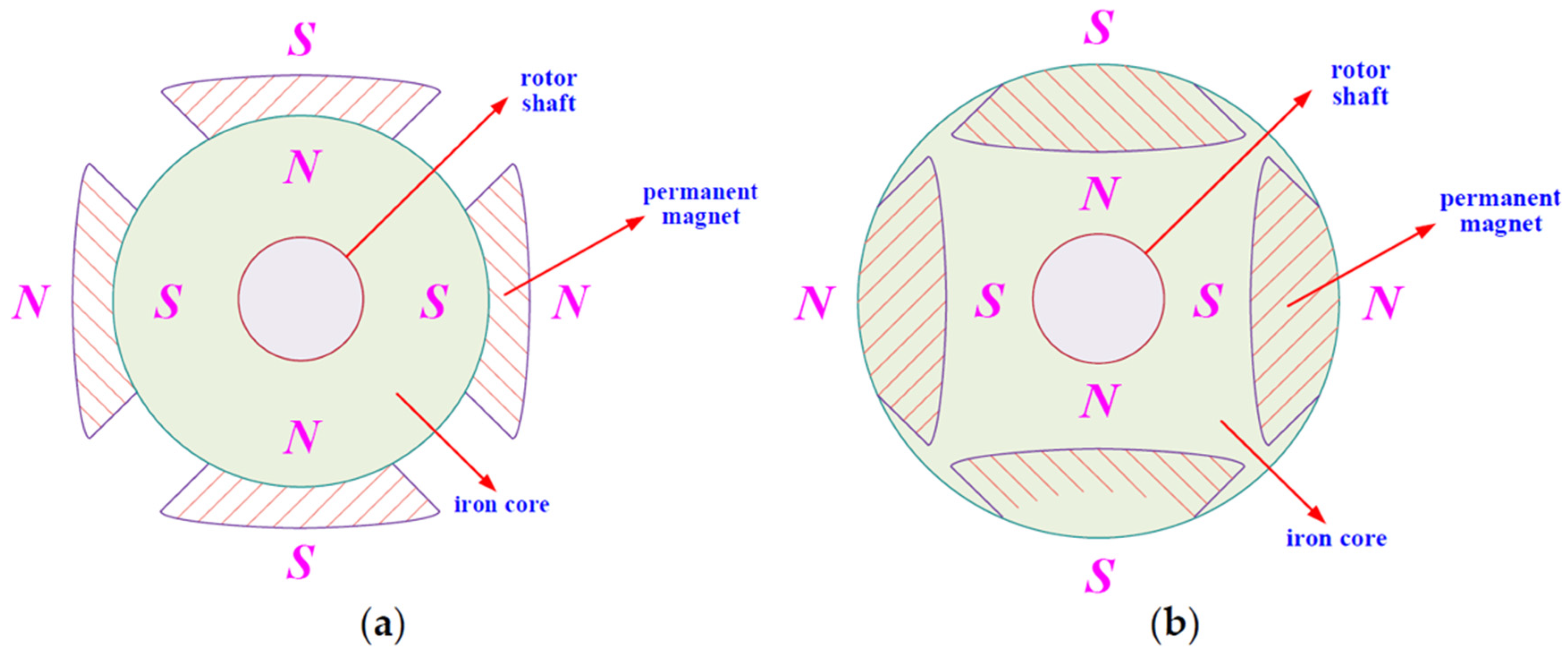
Figure 1. Structure and classification of the permanent magnet synchronous motor types: (a) SPMSM; (b) IPMSM.
Energies 16 02684 g001
Figure 2. Space position map of three different coordinate systems.
Energies 16 02684 g002
Figure 3. Block diagram of the model predictive control algorithm.
Energies 16 02684 g003
Figure 4. The working principle of model predictive control.
Energies 16 02684 g004
Figure 5. Error schematic of the stator flux linkage vector.
Energies 16 02684 g005
Figure 6. Different predictions of the stator flux linkage vector: (a) before; (b) after.
Energies 16 02684 g006
Figure 7. Extended voltage vector control set.
Energies 16 02684 g007
Figure 8. Schematic view of the different voltage vectors on the stator flux linkage vectors.
Energies 16 02684 g008
Figure 9. Diagrammatic sketch of three voltage vectors used to synthesize a reference vector.
Energies 16 02684 g009
Figure 10. Block diagram of the optimization strategy for FCS-MPTC.
Energies 16 02684 g010
Figure 11. Experimental waveforms: (a) three-phase inverter bridge ( 1 : V D S [200 V/div], 2 : I [5 A/div], 3 : V G S [10 V/div]); (b) primary side of the main transformer ( 1 : V [200 V/div], 2 : I [5 A/div]); (c) auxiliary switch ( 1 : V D S [100 V/div], 2 : I [10 A/div], 3 : V G S [10 V/div]); (d) auxiliary transformer ( 1 : V [100 V/div], 2 : I [5 A/div]).
Energies 16 02684 g011
Figure 12. Steady-state experimental waveforms of the d-q-axis current: (a) 300 rpm at 2 N/m ( 1 : i d [2 A/div], 2 : i q [2 A/div]); (b) 500 rpm at 2 N/m ( 1 : i d [2 A/div], 2 : i q [2 A/div]).
Energies 16 02684 g012
Figure 13. Dynamic Performance Evaluation: (a) acceleration and deceleration at 500 r/min with 2 N/m ( 1 : n   [300 rpm/div], 2 : i q [20 A/div], 3 : i A [5 A/div]); (b) current loop following performance ( 1 : i q * [10 A/div], 2 : i q [10 A/div]).
Energies 16 02684 g013
Disclaimer/Publisher’s Note: The statements, opinions and data contained in all publications are solely those of the individual author(s) and contributor(s) and not of MDPI and/or the editor(s). MDPI and/or the editor(s) disclaim responsibility for any injury to people or property resulting from any ideas, methods, instructions or products referred to in the content.