Abstract
Various external-recycle configurations of multi-pass flat-plate solar air collectors were studied theoretically to examine the optimal thermal performance under the same working dimension and operation conditions. An absorber plate and insulation sheet were implemented horizontally and vertically, respectively, into an open rectangular conduit to conduct a recycling four-pass operation, which the device lengthens the air flow channel and increases the air mass flow rate within the collector, and thus, a more heat transfer efficiency is obtained. Four recycling types with different external-recycle patterns were introduced and expected to augment the heat transfer rate due to the turbulent convective intensity through four subchannels in the present study. Coupling energy balances into one-dimensional modeling equations were derived by making the energy-flow diagram within a finite element, which the longitudinal temperature distributions for each subchannel were obtained. The theoretical predictions show that the improved four-pass device is accomplished due to the multiple heating pathways over and under the absorber plate, from which the turbulence intensity augmentation results in the heat transfer rate as compared to that in the device without inserting the absorber plate and insulation sheet (say a downward-type single-pass solar air collector). The theoretical results also show that the external-recycle configuration (say Type C in the present study) acts as an optimal collector thermal efficiency and leading to a beneficial design in multi-pass solar air collectors for improving heat-transfer rate and increasing resident time under the same operation conditions. Theoretical predictions show a higher heat-transfer efficiency for the present recycling configurations up to a maximum 115% device enhancement in comparison to that of a single-pass device. Examination of implementing the absorber plate and insulation sheet on the heat-transfer efficiency enhancement as well as the hydraulic dissipated power increment were also delineated, and deliberated the suitable external-recycle configuration with respect to an economic consideration.
1. Introduction
Flat-plate solar air heaters are the simplest and the most basic device of solar collectors for converting the solar energy into thermal energy to warm the water or air [1]. House heating [2], air conditioning [3], crops drying [4,5] and industrial technologies [6], which are some major applications of solar air heaters. The limitation of low convective heat-transfer coefficient is faced by the viscous laminar sublayer in the turbulent boundary layer adjacent to the absorber plate surface. Many efforts were made to destroy viscous laminar sublayer in attaining augmented heat transfer characteristics [7,8] by in view of the designing parameters with different strategies of roughening the surface [9,10], forced convection [11,12], air turbulence [13,14] and recycling operations [15,16]. The design concept for improving device performance of heat transfer is to increase either the residence time or the convective transfer coefficient. In order to enlarge the fluid velocity as well as strengthening the forced convection, several researchers reported that various configurations of double- [17,18,19] or multi-pass [16] operations with internal or external recycle could enhance heat- and mass-transfer rates, which the increase of power consumption was required accordingly. Therefore, both technical and economic feasibilities for the improved design must be considered not only the increase in heat transfer efficiency but also the hydraulic dissipated power penalty. The double- or multi-pass operation was carried out to create an extended heating area (above and underneath the absorber plate) of operating flat-plate solar air heaters [20,21,22], which an adjustable aspect ratio for a rectangular flat-plate solar air heater was expected to augment the forced convection, and thus, the heat-transfer efficiency enhancement was accomplished with constant flow rate [23]. However, extracting the more thermal energy from the improved solar air collectors [24] was shown to require additional power consumption at the expense of the increase of friction loss due to external air recirculation accompanying with the increases in fluid velocity. So there exists an optimal design in recycling solar air collectors with more efficient thermal energy utilization [25] to reach a higher collector thermal performance based on the economic viewpoint.
The previous work [21] showed that a substantial thermal performance enhancement of the multi-pass solar air collector was achieved as compared to the single- and double-pass devices. In the present study, four external-recycle configurations of multi-pass solar air collectors were proposed for comparisons to examine both advantageous and disadvantageous effects in promoting the turbulence intensity and remixing the inlet temperatures on the thermal performance, respectively. Various external refluxes were introduced in multi-pass devices to mitigate the remixing effect and to boost convective turbulence intensity, and thus, the optimal device performance under different configurations and operating conditions was elevated substantially. It is believed that availability of such recycling multi-pass solar air collectors presented here to consider the technical and economic feasibilities is the value of this work for further practical applications. Moreover, the comparisons will contribute to realize the optimal design of solar air collectors based on the economic standpoint with considering both heat-transfer efficiency improvement and hydraulic dissipated power increment. The purpose of this study is to develop the theoretical modeling for the different configurations and to evaluate the appropriate selection of operation conditions such as recycle ratio and air mass flow rate. A simplified mathematical formulation was developed for solving the thermal efficiency of solar air collectors and would be a considerable contribution to exploring heat transfer problems with recycling multi-pass operations.
2. Flow Patterns and Mathematical Statements
2.1. Energy Balances Equations
New designs of recycling multi-pass solar air collectors insert an absorber plate and an absorber insulation sheet horizontally and vertically, respectively, to divide the parallel-plate conduit into four subchannels and weld another insulation bottom plate on the lower channel. Figure 1a,b illustrate the schematic front view and side view for operating with various external refluxes, respectively, which the widths and heights of four subchannels are of vertical heights and , and horizontal widths and , respectively. Two parameters of aspect ratios and are movable and adjustable. Air flows into each lower subchannel on both left- and right-hand sides along the longitude direction while flowing out the opposite direction from each upper subchannels on both left- and right-hand sides, as shown in Figure 1b. A solar air collector may be constructed of stainless steel and a black coating stainless-steel absorber plate is welded into the parallel-plate open conduit. The whole solar collector is wrapped except the top glass covers with foamed plastic substrate, which a silicon layer is coated between the plastic substrate and stainless steel to prevent losses from the environment.
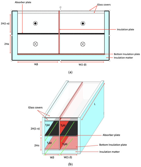
Figure 1.
Schematic diagrams of a recycling multi-pass solar air collector: (a) Front view ( Flow out and
  Flow in); (b) Side view.
The motivation of the present designs of this recycling operations was to heat up the air flowing four times through the subchannels of the solar air collector with increasing air velocity and resident time, and hence, the multi-pass operation is then accomplished. Four external-recycle configurations were operated with various air mass flow rate and presented in Figure 1b as an illustration. The augmented convective heat-transfer coefficients were significant benefit to release solar heat from absorbent plate to flowing air due to the increase of the volumetric flow rate in each subchannel, which both turbulence intensity and remixing inlet temperature were examined to select various flow configurations with the external recycle. Various external-recycle types of multi-pass operations are presented to evaluate the heat transfer efficiency for comparisons.
The thermal performance of a solar collector was derived by an energy balance, which illustrates the basic principles in an air heating collector to model the physical situation for design calculations with the foundations of a number of simplified assumptions. A relatively simple analysis yields very useful results, as shown in Figure 2, that indicates the absorber surface with means of transferring the absorbed solar energy into useful energy gain under envelopes transparent to solar radiation and bottom insulation for reducing heat losses. Energy balances were made with the energy-flow diagram in a finite fluid element of the absorber plate, glass cover, bottom plate, and air flowing into four subchannels, respectively.
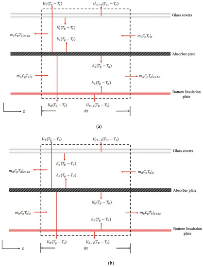
Figure 2.
Energy balances were made with the energy-flow diagram in a finite fluid element: (a) Subchannels on the left-hand side; (b) Subchannels on the right-hand side.
The same derived procedure performed by following our previous work [21] and rearranging with the dimensionless group , one obtains:
where detailed derivations of these four simultaneous ordinary equations with all the coefficients , , and are expressed in terms of the convective heat-transfer coefficients, loss coefficients and physical properties as follows:
and
in which
2.2. Heat-Transfer Coefficients and Collector Thermal Efficiency
The heat-transfer coefficients for all parts of the solar air collector were lumped into the thermal resistance network, as presented in Figure 3. The incident radiation passes through both the inner cover and outer cover from the ambient air with heat transfer coefficients, which all the constants , , and are incorporated [26,27] by the empirical expressions:
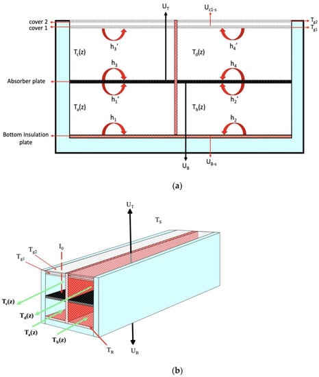
Figure 3.
The heat-transfer coefficients for all parts of the solar air collector: (a) Front view; (b) Side view.
The forced convective heat-transfer coefficient for air flowing through two parallel-flat plates is required to consider the heat transfer characteristics of the solar air collector and collector-storage walls, and the heat transfer coefficients between air and each duct wall may be assumed to be equal, i.e.,
which were derived from Kay’s data [28] as follows:
The modification was made McAdams [29] for turbulent flow in a short conduit:
while the equation presented by Heaton et al. [30] may be used for laminar flow:
in which, the hydraulic diameter denotes of each subchannel for calculating the Reynolds numbers, which was expressed in terms of characteristic dimensions in multi-pass operations, , , and , and in the single-pass operation, , respectively:
The average velocities and Reynolds numbers of the lower and upper subchannels in both left- and right-hand sides are:
The overall heat loss coefficient was estimated summing the top and bottom loss coefficients and , respectively, and neglecting edge loss then goes as follows:
The heat transfer coefficient from glass covers 1 through glass cover 2 to the ambient air may be expressed in terms of thermal resistances in series as
or
where Hottel’s empirical equation [31] was used to estimate the heat transfer coefficient for free convection of air as
and the following empirical equation given by McAdams [29] was used to calculate the convective heat-transfer coefficient for air flowing over the outside collector surface:
A mean radiant temperature equal to the mean fluid temperature was assumed to estimate the radiation coefficients as follows:
2.3. Temperature Distributions
2.3.1. Internal Recycling at Upper Subchannel (Type A)
The airflow (with air mass flow rate and inlet temperature ) was premixed with the outlet airflow from the upper subchannel c (with a recycle air mass flow rate ) before entering the lower subchannel a on the left-hand side of a four-pass device. Likewise, the exiting airflow from the upper subchannel a which is directed to the upper channel (with air mass flow rate and temperature ) was premixed with the airflow exiting from the upper subchannel d (with a recycle mass flow rate ) before entering the lower subchannel b on the right-hand side. Four conventional blowers situated at the inlet and outlet of each subchannel regulate the recycling mass flow rate. The theoretical solutions of the temperature distributions to the multi-pass recycling device of Type A, as shown in Figure 4, are obtained by associating with the following boundary conditions and air mass flow rate in each subchannel as follows:
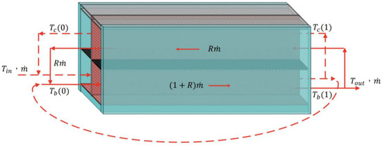
Figure 4.
Schematic diagram of a recycling multi-pass solar air collector (Type A).
Meanwhile, the collector thermal efficiencies () were calculated the actual useful energy gained by the air flow in and out four subchannels, incident solar radiation, and average absorber plate temperature, i.e.,
Equating the terms on the right-hand side of Equation (58) yields the average absorber temperature as
The air mass flow rates of Type A and other external-recycle types are demonstrated and presented, as summarized in Table 1 as well as the boundary conditions in Table 2. The theoretical predictions of collector thermal efficiencies and outlet temperatures are expressed and listed in Table 3. Hereafter, the schematic diagrams of four external-recycle types are shown graphically in Figure 4, Figure 5, Figure 6 and Figure 7 with labeling Types A, B, C and D, correspondingly.

Table 1.
Air mass flow rates of various configurations for Type A to Type D.
Table 2.
Boundary conditions of various configurations for Type A to Type D.
Table 3.
Theoretical predictions of the collector thermal efficiencies and outlet temperatures for Type A to Type D.
2.3.2. External Recycling at Lower Subchannel (Type B)
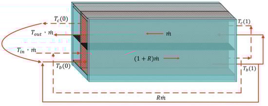
Figure 5.
Schematic diagram of a recycling multi-pass solar air collector (Type B).
2.3.3. External Recycling at Upper Subchannel (Type C)
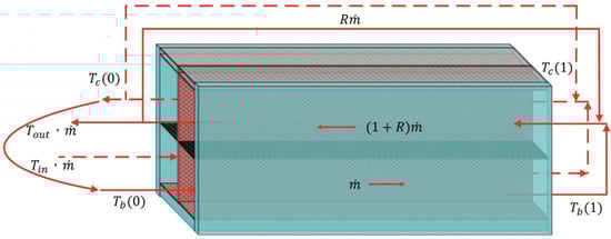
Figure 6.
Schematic diagram of a recycling multi-pass solar air collector (Type C).
2.3.4. Equal Recycling of Both Subchannels (Type D)
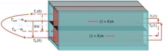
Figure 7.
Schematic diagram of a recycling multi-pass solar air collector (Type D).
2.4. Hydraulic Dissipated Power
The friction loss in each subchannel may be estimated by
where and denote the bulk velocities in the each subchannel and the equivalent hydraulic diameters, respectively. The is the Fanning factor [32] in terms of the Reynolds number, . For laminar flow
while for the turbulent flow
The hydraulic dissipated power, , may be defined as
The hydraulic dissipated power consumption increment for the multi-pass and double-pass flat-plate devices are defined respectively, as follows:
in which is the increase of the hydraulic dissipated power consumption as compared to the downward single-pass operation of .
3. Collector Efficiency Improvement and Further Collector Efficiency Enhancement
3.1. Calculation Procedure for Collector Efficiency Improvement
The theoretical formulations of four-pass solar air collector were derived as the same concept performed in our previous work [15], which the experimental runs of the two-pass solar air collectors were conducted and the agreement between the experimental results and theoretical predictions is quite well. Moreover, the mathematical formulations are coupled simultaneous differential equations, and the numerical solutions were obtained with the use of the 4th order Runge-Kutta method to discretize the differential equations and validate them with various iterative grids until the convergence tolerance is required during the calculation procedure. The outlet temperatures were solved numerically using the 4th-order Runge-Kutta method and the appropriate boundary conditions. The collector thermal efficiencies in various external-recycle devices could be predicted once the outlet temperatures were obtained. The calculation procedure for theoretical predictions of collector thermal efficiencies and collector efficiency improvements was performed as follows: Firstly, the prescribed collector geometries ( = 0.09 m2, = 0.1 m, = 0.3 m, = 0.3 m, 0 , ), system properties ( = 0.96, = 0.94, = 0.8, = 0.94, = 0.875) and operating conditions ( 0.0107, 0.0161 and 0.0214 kg s−1, 30 ± 0.1 °C, 30 ± 0.1 °C, 830 ± 20 and 1100 ± 20 W m−2, 1.0 m s−1) are given as well the initial guesses of the mean temperatures , , , are estimated to calculate the heat transfer coefficients and temperature distributions of four subchannels. Secondly, the new mean temperature values of , , , were re-calculated with the use of all appropriate equations to proceed the iteration procedure until the convergence tolerance is reached to meet the final calculated values, and thus, the corresponding collector thermal efficiencies can be obtained.
The collector efficiency improvement is measured by calculating the percentage increment in the device performance by employing the recycling multi-pass and double-pass solar air collectors, respectively (say or ), which is calculated basing on the downward-type single-pass device under the same total flow rate ṁ and the same working dimensions. The collector efficiency improvements, say and , are thus evaluated by operating the collector thermal efficiency of the double-pass flat-plate device and the present multi-pass devices as compared to the downward-type single-pass device:
in which and denote collector efficiencies of the multi-pass flat-plate, double-pass, and downward-type single-pass devices, respectively. Comparisons were made on the collector efficiency improvement for the multi-pass solar air collector with various external-recycle operations. Comparisons were made on the collector thermal efficiency and collector efficiency improvement for various external-recycle configurations in both multi-pass flat-plate solar air collectors, as depicted in Table 4 and Table 5 for and , respectively.
Table 4.
Effects of external-recycle types on collector efficiency improvements. (, ).
Table 5.
Effects of external-recycle types on collector efficiency improvements. (, ).
3.2. Further Collector Efficiency Enhancement
The further collector efficiency enhancement is calculated by operating multi-pass solar air collectors with respect to the device of the double-pass solar air collector as:
The further collector efficiency enhancements by employing the multi-pass operations for various external-recycle configurations and incident radiations are summarized in Table 5 with .
4. Results and Discussion
The theoretical predictions of collector thermal efficiencies of multi-pass solar air collectors under various external-recycle configurations with recycle ratio as a parameter are summarized in Table 4 and Table 5 for , , and and , respectively. As expected, the higher air mass flow rate and recycle ratio result in higher collector thermal efficiency owing to the increased flowing air velocity associated with the augmented convective heat-transfer coefficient by operating recycling multi-pass solar air collectors, as confirmed in Table 4 and Table 5. The results can also be observed from Table 4 and Table 5, which the order of the device performance of collector thermal efficiencies by operating multi-pass solar air collectors with external recycle is obtained as follows: Type C > Type D > Type B > Type A. The smallest collector efficiency improvement is found under operating Type A, which leads to the less thermally efficient configuration among all presented external-recycle operations. However, the collector efficiency improvement is in reverse order with air mass flow rate.
In addition, the effects of air mass flow rate, recycle ratio and incident solar radiation on the collector thermal efficiency of Type C as an illustration were presented graphically in Figure 8. The outlet temperature which is directed to the upper subchannel on the right-hand side of Type C with the larger air mass flow rate to create qualitatively a higher heat transfer of natural convection. Moreover, the reason why the collector thermal efficiency of Type C > Type D under the same air mass flow rate in the upper subchannel is Type D illustrating the disadvantage of external-recycle remixing effect at the inlet in the lower subchannel. Type C also generates a larger air mass flow rate by remixing the external recycle as compared to Type A and Type B, which is beneficial to heighten the collector thermal efficiency under the same working dimension. Thus, the more useful energy gained through the upper subchannel for Type C was achieved with a higher outlet temperature than any other types. Moreover, the recycle ratio plays an important role to enhance heat transfer rate substantially due to the turbulent intensity augmentation of Type C. The highest collector thermal efficiency improvements were accomplished up to 112.8% and 115.1% with and for and for operating Type C, respectively, as seen in Table 4 and Table 5 for illustrations. Restated, implementing the multi-pass solar air collector instead of using double-pass and single-pass devices shows a favorable prospect to considerably enhance the collector’s thermal efficiency, as illustrated in Figure 8. It is believed that the availability of such a simplified mathematical modeling as developed is the value of the present work to design and analyze multi-stream problems for recycling multi-pass solar collectors.
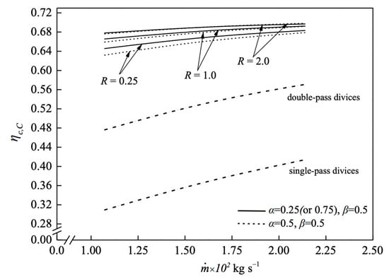
Figure 8.
Comparisons of collector thermal efficiency among single-, double- and multi-pass devices.
The theoretical predictions of various external-recycle Types A, B, C and D are presented in this section, which the qualitative and quantitative graphs and tables were presented and demonstrated the optimal thermal efficient type for the best design through the discussion. The further collector efficiency enhancement of the multi-pass device decreases with the air mass flow rate, incident solar radiation and recycle ratio, as calculated and listed in Table 6. The highest further collector thermal efficiency of 60.97% is observed at the lower air mass flow rate, recycle ratio and incident solar radiation.
Table 6.
Further collector efficiency enhancements of four multi-pass types. ( and .
Meanwhile, the forced convective heat-transfer coefficient increases with two aspect ratios and as parameters for multi-pass operations resulting in considerably improved devices, as shown in Figure 9a,b with respect to and , respectively, while both aspect ratio variations on the collector thermal efficiency are shown in Figure 10 and Figure 11 with inlet air mass flow rate as a parameter, respectively. The influence of aspect ratio on the collector thermal efficiency is relatively insignificant to that of the aspect ratio for Type C as an illustration.
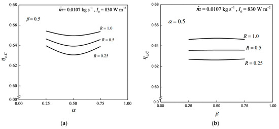
Figure 9.
Effects of aspect ratios on collector thermal efficiencies: (a) Aspect ratio ; (b) Aspect ratio β variations.
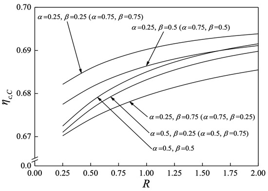
Figure 10.
Effects of aspect ratio variations on the collector thermal efficiency.
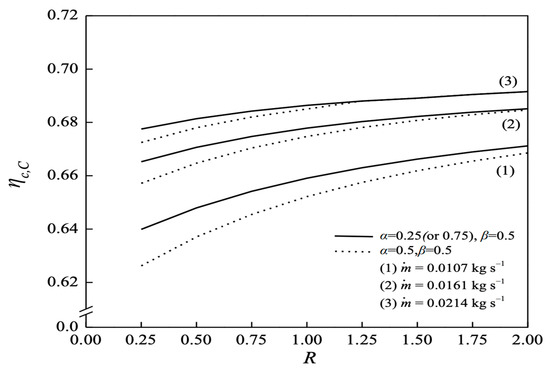
Figure 11.
Effects of aspect ratios and inlet air mass flow rates on the collector thermal efficiency.
The hydraulic dissipated power consumption increments of four external-recycle configurations are based on the hydraulic dissipated power consumption in a single-pass device with aspect ratio and recycle ratio as parameters, as indicated in Figure 12 for Type C and Figure 13 for comparisons of all external-external configurations. The ratios of the collector efficiency improvement and the hydraulic dissipated power consumption increment are considered the economic feasibility in design and operation for multi-pass solar air collectors, as presented graphically in Figure 12 with respect to various air mass flow rates. The multi-pass operation represents more manners from the turbulence promotion with the heat transfer augmentation in comparison to the conventional and simplest geometry of the single-pass and double-pass solar air collectors.
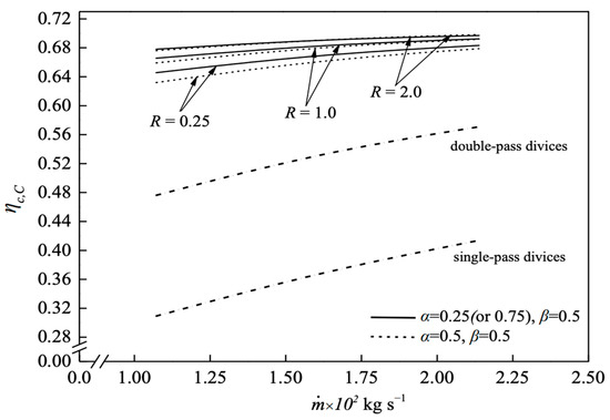
Figure 12.
The ratio of the collector efficiency improvement and hydraulic dissipated power consumption increment.
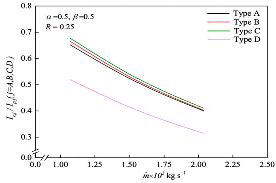
Figure 13.
The ratio of the collector efficiency improvement and hydraulic dissipated power consumption increment for four external-recycle types.
In general, the extensive increment in the hydraulic dissipated power consumption by raising the recycle ratio strengthens the turbulence intensity magnitude. The higher ratios of indicate the extent of collector efficiency improvements of multi-pass solar air collectors, which represents the recycling multi-pass solar air collector compensating the extra hydraulic dissipated power consumption. The hydraulic dissipated power consumption increment of all external-recycle types is insignificant among all types, but Type C is the highest one. The graph depicts a relative high ratio of the collector efficiency improvement and hydraulic dissipated power consumption increment under Type C in Figure 12 as compared to the other types in Figure 13 with the order of Type C > Type B > Type A > Type D. Although at the expense of a moderate amount of hydraulic dissipated power consumption, the recycling multi-pass solar air collector accomplishes a higher useful energy gain. An appropriate selection of the operating parameters for the recycling multi-pass flat-plate solar air collectors would be regarded as a beneficial decision rule for economic and technical feasibility.
5. Conclusions
Comparisons on the proposed four-pass external-recycle configurations involve the advantageous effect of the convective heat-transfer coefficient enhancement as well as the disadvantageous effect of remixing temperature at the entrance. The introduction of the external-recycle effect offers an appropriate selection to provide economic consideration for recycling multi-pass operations with the higher ratio of the heat-transfer efficiency improvement relative to the hydraulic dissipated power consumption increment, which offset the disadvantage of mixing effect and assure the advantage of the velocity profile to obtain the more efficient specification settings. Restated, recycling multi-pass operations provide the desirable effect of increasing air velocity as well as the heat-transfer coefficient, which could compensate for the undesirable effect of inlet remixing associated with decreasing temperature driving force, resulting in collector efficiency improvement.
The present designs of practical applications for solar air collectors are a beneficial decision rule with those comparisons. Four external-recycle configurations of multi-pass solar air collectors were designed and developed theoretically based on both the collector thermal efficiency enhancement and hydraulic dissipated energy increment to understand the appropriate selection of optimal design in according to the economic consideration. The effect of external recycle on heat transfer through multi-pass operations has been analyzed. The ordinary differential equations for air temperature distributions in each flow subchannel were derived based on energy balances with the assumptions of uniform temperatures and velocities over the cross-sectional area of the subchannels. The calculation results confirmed that implementing multi-pass operations with heat-transfer coefficient augmentation results in the collector efficiency improvement up to 115% in comparison to the single-pass solar air collector, albeit that is accompanied the additional hydraulic dissipated power consumption. Operating these external-recycle types leads to a better device performance due to the strengthened turbulence intensity, and thus the collector thermal efficiency is achieved. The recycling multi-pass solar air collector is examined for four external-recycle configurations under various operation conditions in this theoretical study. It is concluded that considerable improvement in heat transfer is obtainable if solar air collector is operated with external recycle under a larger recycle ratio. Collector thermal efficiency of recycling multi-pass solar air collectors increases with increasing recycle ratio, air mass flow rate and incident solar radiation but collector efficiency improvement and further collector efficiency enhancement decreases with air mass flow rate. It is shown that more than 40% of Type A and up to 115% of Type C on collector efficiency improvement is obtainable in the present configurations. The advantage of Type C is evident for accomplishing optimal selection from the standpoint on economic efficiency as well as the collector thermal efficiency and collector efficiency improvement . It is believed that the external-recycle operations would be also applicable to other kinds of heat exchangers such as shell-and-tube heat exchangers and recuperators, and even applicable to mass exchangers such as membrane extraction contactors and thermal diffusion columns.
Author Contributions
C.-D.H.: funding acquisition, conceptualization, methodology, data collection and analysis. H.C.: funding acquisition, writing—original draft, analysis and interpretation of data. C.-W.Y.: data curation, investigation. C.-A.N.: investigation, writing—review, editing. P.-C.H.: data curation, formal analysis. All authors have read and agreed to the published version of the manuscript.
Funding
This research received no external funding.
Institutional Review Board Statement
Not applicable.
Informed Consent Statement
Not applicable.
Data Availability Statement
Data are contained within the article.
Acknowledgments
The authors wish to thank the National Science and Technology Council (NSTC) of the Republic of China (Taiwan) for the financial support.
Conflicts of Interest
The authors declare no conflict of interest.
Nomenclature
| Ac | surface area of the collector (m2) |
| coefficients, | |
| specific heat of air at constant pressure () | |
| equivalent hydraulic diameter (), | |
| equivalent hydraulic diameter of the single-pass device (), | |
| further collector efficiency enhancement, | |
| Fanning friction factor | |
| coefficients, | |
| half of total channel thickness () | |
| convection coefficient between the bottom and lower subchannel () | |
| convection coefficient between the absorber plate and lower channel () | |
| convection coefficient between the absorber plate and upper channel () | |
| convection coefficient between the inner cover and upper channel () | |
| convective coefficient between two glass covers () | |
| radiation coefficient between two glass covers () | |
| radiation coefficient from the outer cover to the ambient () | |
| radiation coefficient between the inner cover and absorber plate () | |
| radiation coefficient between absorber plate and bottom plate () | |
| convective coefficient for air flowing over the outer glass cover () | |
| Incident solar radiation () | |
| percentage of power consumption increment of Type A | |
| percentage of power consumption increment of Type B | |
| percentage of power consumption increment of Type C | |
| percentage of power consumption increment of Type D | |
| percentage of collector efficiency improvement for Type A | |
| percentage of collector efficiency improvement for Type B | |
| percentage of collector efficiency improvement for Type C | |
| percentage of collector efficiency improvement for Type D | |
| percentage of collector efficiency improvement in double-pass device | |
| thermal conductivity of the air () | |
| channel length () | |
| the friction loss in each subchannel (), | |
| friction loss of downward-type single-pass device (), | |
| air mass flow rate in each subchannel (), | |
| ṁ | Inlet air mass flow rate () |
| Nusselt number in the single-pass collector | |
| Nusselt number in each subchannel, | |
| power consumption for the single-pass solar air collector , | |
| power consumption for the multi-pass flat-plate solar air collector , | |
| useful energy gained by flowing air | |
| recycle ratio | |
| Rayleigh Number | |
| Reynolds Number in the single-pass collector | |
| Reynolds Number in each subchannel, | |
| axial fluid temperature distribution in the lower subchannel of left-hand side (K) | |
| axial fluid temperature distribution in the lower subchannel of right-hand side (K) | |
| axial fluid temperature distribution in the upper subchannel of left-hand side (K) | |
| axial fluid temperature distribution in the upper subchannel of right-hand side (K) | |
| the mixing inlet temperature at , | |
| the outlet temperature at , | |
| average temperature of , | |
| temperature of the inner glass cover | |
| temperature of the outer glass cover | |
| average temperature of the inner glass cover | |
| average temperature of the outer glass cover | |
| the inlet temperature | |
| temperature of absorber plate | |
| average temperature of absorber plate | |
| temperature of bottom plate | |
| ambient temperature | |
| loss coefficient from the bottom plate to the ambient () | |
| loss coefficient from the surfaces of edges and bottom to the ambient () | |
| loss coefficient from the inner cover to the ambient () | |
| overall loss coefficient () | |
| loss coefficient from the top to the ambient () | |
| the average velocity of the single-pass device () | |
| the average velocity of the lower channel (), | |
| collector width () | |
| axial coordinate along the flow direction () | |
| Greek Letters | |
| vertical aspect ratio | |
| absorptivity of the absorber plate | |
| β | horizontal aspect ratio |
| collector efficiency of the multi-pass flat-plate solar air collector of Type A | |
| collector efficiency of the multi-pass flat-plate solar air collector of Type B | |
| collector efficiency of the multi-pass flat-plate solar air collector of Type C | |
| collector efficiency of the multi-pass flat-plate solar air collector of Type D | |
| collector efficiency of the double-pass flat-plate solar air collector | |
| collector efficiency of the downward-type single-pass device | |
| transmittance of glass covere missivity of glass cover emissivity of absorber plate | |
| air density () | |
| air viscosity () | |
| Stefan-Boltzmann constant () () | |
| ξ | dimensionless channel position |
References
- Seluck, M.K. Solar Air Heaters and Their Applications; Sayigh, A.A.M., Ed.; Academic Press: New York, NY, USA, 1977. [Google Scholar]
- Badescu, V.; Sicre, B. Renewable energy for passive house heating. Part I. Building description. Energy Build. 2003, 35, 1077–1084. [Google Scholar] [CrossRef]
- Lucas, M.; Martinez, P.; Sanchez, A.; Viedma, A.; Zamora, B. Improved hydrosolar roof for buildings’ air conditioning. Energy Build. 2003, 35, 963–970. [Google Scholar] [CrossRef]
- Design, S.S. Experimental investigation and analysis of a solar drying system. Energy Convers. Manag. 2013, 8, 27–34. [Google Scholar]
- El-Sebaii, A.A.; Shalaby, S.M. Experimental investigation of an indirect-mode forced convection solar dryer for drying thymus and mint. Energy Convers. Manag. 2013, 74, 109–116. [Google Scholar]
- Bari, E.; Noel, J.Y.; Comini, G.; Cortella, G. Air-cooled condensing systems for home and industrial appliances. Appl. Therm. Eng. 2005, 25, 1446–1458. [Google Scholar] [CrossRef]
- Singh, S.; Dhiman, P. Thermal performance of double pass packed bed solar air heaters—A comprehensive review. Renew. Sustain. Energy Rev. 2016, 53, 1010–1031. [Google Scholar] [CrossRef]
- Ravi, R.K.; Saini, R.P. A review on different techniques used for performance enhancement of double pass solar air heaters. Renew. Sustain. Energy Rev. 2016, 56, 941–952. [Google Scholar] [CrossRef]
- Prasad, B.N.; Saini, J.S. Effect of artificial roughness on heat transfer and friction factor in solar air heater. Sol. Energy 1988, 41, 555–560. [Google Scholar] [CrossRef]
- Khimsuriya, Y.D.; Patel, D.K.; Said, Z.; Panchal, H.; Jaber, M.M.; Natrayan, L.; El-Shafay, A.S. Artificially roughened solar air heating technology-A comprehensive review. Appl. Therm. Eng. 2022, 214, 118817. [Google Scholar] [CrossRef]
- Kreith, F.; Kreider, J.F. Principles of Solar Engineering; McGraw-Hill: New York, NY, USA, 1978. [Google Scholar]
- Luan, N.T.; Phu, N.M. Thermohydraulic correlations and exergy analysis of a solar air heater duct with inclined baffles. Case Stud. Therm. Eng. 2020, 21, 100672. [Google Scholar] [CrossRef]
- Prasad, B.N.; Kumar, A.; Singh, K.D.P. Optimization of thermos hydraulic performance in three sides artificially roughened solar air heaters. Sol. Energy 2015, 111, 313–319. [Google Scholar] [CrossRef]
- Abdullah, A.S.; Abou Al-sood, M.M.; Omara, Z.M.; Bek, M.A.; Kabeel, A.E. Performance evaluation of a new counter flow double pass solar air heater with turbulators. Sol. Energy 2018, 173, 398–406. [Google Scholar] [CrossRef]
- Ho, C.D.; Lin, C.S.; Chuang, Y.C.; Chao, C.C. Performance of wire mesh packed double-pass solar air heaters with external recycle. Renew. Energy 2013, 57, 479–489. [Google Scholar] [CrossRef]
- Kumar, A.; Singh, A.P.; Singh, O.P. Efficient designs of double-pass curved solar air heaters. Renew. Energy 2020, 160, 1105–1118. [Google Scholar] [CrossRef]
- Satcunanathan, S.; Deonarine, S.A. Two-pass solar air heater. Sol. Energy 1973, 15, 41–49. [Google Scholar] [CrossRef]
- Wijeysundera, N.E.; Ah, L.L.; Tjioe, L.E. Thermal performance study of two-pass solar air heaters. Solar Energy 1982, 28, 363–370. [Google Scholar] [CrossRef]
- Hassan, H.; Abo-Elfadl, S. Experimental study on the performance of double pass and two inlet ports solar air heater (SAH) at different configurations of the absorber plate. Renew. Energy 2018, 116, 728–740. [Google Scholar] [CrossRef]
- Garg, H.P.; Sharma, V.K.; Bhargava, A.K. Theory of multi-pass solar air heaters. Energy 1985, 10, 589–599. [Google Scholar] [CrossRef]
- Ho, C.D.; Yeh, C.W.; Hsieh, S.M. Improvement in device performance of multi-pass flat-plate solar air heaters with external recycle. Energy 2005, 30, 1601–1621. [Google Scholar] [CrossRef]
- Alam, T.; Kim, M.H. Performance improvement of double-pass solar air heater- A state of art of review. Renew. Sustain. Energy Rev. 2017, 79, 779–793. [Google Scholar] [CrossRef]
- Yeh, H.M.; Lin, T.C. The effect of collector aspect ratio on the collector efficiency of flat-plate solar air heaters. Energy 1995, 20, 1041–1047. [Google Scholar] [CrossRef]
- Dhiman, P.; Singh, S. Thermal performance assessment of recyclic double-pass flat and V-corrugated plate solar air heaters. Int. J. Sustain. Energy 2015, 36, 78–100. [Google Scholar] [CrossRef]
- Muley, A.; Manglik, R.M. Experimental study of turbulent flow heat transfer and pressure drop in a plate heat exchanger with chevron plates. J. Heat Transf. 1999, 121, 110–117. [Google Scholar] [CrossRef]
- Klein, S.A. Calculation of monthly average transmittance-absorptance product. Sol. Energy 1979, 23, 547–551. [Google Scholar] [CrossRef]
- Duffie, J.A.; Beckman, W.A. Solar Engineering of Thermal Processes; Wiley: New York, NY, USA, 1980. [Google Scholar]
- Kays, W.M. Convective Heat and Mass Transfer; McGraw-Hill: New York, NY, USA, 1980. [Google Scholar]
- McAdams, W.H. Heat Transmission; McGraw-Hill: New York, NY, USA, 1954. [Google Scholar]
- Heaton, H.S.; Reynolds, W.C.; Kays, W.M. Heat transfer in annular passages. simultaneous development of velocity and temperature fields in laminar flow. Int. J. Heat Mass Transf. 1964, 7, 763–781. [Google Scholar] [CrossRef]
- Hottel, H.C.; Woertz, B.B. Performance of flat-plate solar-heat collectors. Trans. ASME 1942, 64, 91–104. [Google Scholar] [CrossRef]
- Welty, J.R.; Wicks, C.E.; Wilson, R.E. Fundamentals of Momentum, Heat, and Mass Transfer, 3rd ed.; John Wiley & Sons: New York, NY, USA, 1984. [Google Scholar]
Disclaimer/Publisher’s Note: The statements, opinions and data contained in all publications are solely those of the individual author(s) and contributor(s) and not of MDPI and/or the editor(s). MDPI and/or the editor(s) disclaim responsibility for any injury to people or property resulting from any ideas, methods, instructions or products referred to in the content. |
© 2023 by the authors. Licensee MDPI, Basel, Switzerland. This article is an open access article distributed under the terms and conditions of the Creative Commons Attribution (CC BY) license (https://creativecommons.org/licenses/by/4.0/).