1. Introduction
The use and manufacture of Electric Vehicles (EVs) have increased in recent years, one of the factors contributing to this growth is the intention of many countries to make the transition from combustion vehicles to EVs, this transition will promote significant advantages regarding emissions of CO
2 in the atmosphere [
1,
2,
3]. However, with the increased circulation of EVs in the world fleet, there is a need to increase the number of electric charging stations for EVs and with that, the need to analyze the impacts of these recharges on the energy system and their costs [
4,
5,
6]. One of the ways that contribute to the reduction of costs, as well as the improvement and even greater use of non-pollution is the use of Photovoltaic (PV) systems as a way of supplying energy to recharge these vehicles [
7,
8,
9,
10].
Among the types of Renewable Energy Resources (RER), photovoltaic energy is one of the modalities used in the generation of electrical energy. The process of converting solar energy into electricity is carried out through photovoltaic panels that can be installed in different ways, allowing their use in different configurations in electric vehicle charging stations.
A classic example of the possibility of installing these systems together is the use of PV panels on the roof of parking lots, providing shade for parked vehicles, in addition to generating electricity during periods of availability of solar energy and using this energy to recharge EVs or even insert this energy that is being generated into the grid.
However, when we analyze this process in practice, we verify that it can be optimized using an Energy Storage System (ESS) since the excess energy generated by the PV system can be stored in the batteries, being discharged at other times that generation is not observed. The storage system can also contribute by smoothing the power generated by the PV system since this is an intermittent source. It should be noted that for the experiments carried out in this work, a State of Charge (SoC) varying between 20% (SoC min) and 100% (SoC max) was used, which results in a Depth of Discharge (DoD) of 80%, which It is the manufacturer’s recommendation to obtain 3000 battery life cycles. It should also be considered that storage systems have several other types of applications such as voltage regulation, power factor correction, and frequency regulation, among others [
11,
12,
13,
14,
15]. In [
16], a Battery Energy Storage System (BESS) is used to contribute to the stability of energy generation of a wind farm, the work presents different applications of the system, such as power smoothing and power factor correction.
When analyzing the studies on the impact of a massive insertion of EVs on the electric grid, it is possible to verify that the current configurations of the system will not support this change, for this, the BESS can contribute to the stability of the system. In [
17], a study is presented on the impacts of the insertion of EVs in the grid through the Monte Carlo method, the study showed that the system will not support the increase in demand as early as 2026. Furthermore, in [
18], the penetration of EVs in the low voltage distribution grid is analyzed, taking into account charging time, charging method, and characteristics.
In addition to the difficulties related to the costs of EVs, another criterion that must be considered when adopting these means of transport concerns the electrical impacts that the connection of these loads causes on the electrical grid at the time of insertion. A considerable input of loads with relevant powers in the grid can cause disturbances in the stability of the energy supply, from voltage sags, even current peaks, and frequency variations, as shown in studies by [
19].
Some ways to reduce these impacts are used practically, as is the case of Vehicle-to-Grid (V2G) technology, in which the vehicle can be connected to the grid and supply energy to it, at times when the user will not need to use the vehicle within this period, with this, the vehicle can contribute to the stability of the system, acting in the control of demand peaks [
20]. However, another way to get around these problems is to use alternative sources of energy, with an emphasis on PV energy. By integrating a PV system and the charging station, it is already possible to have a considerable reduction in the impact on the electrical grid, since the recharges will be supplied by energy from the sun, as shown in [
21].
Much research in this area nowadays is focused on projects with integration between PV systems and electric vehicle chargers. In [
22], a charging system for EVs based on a PV system is proposed, the work presents graphs of load curves and some applications that can be used in the system. In [
23], the management and control system of a charging station configuration with an integrated PV system is presented. In [
24], an integration configuration between the electric vehicle charging system, PV system, and BESS is also presented, in this case, a multi-objective optimization (MCTLBO) is performed for optimization in the size design. of the PV/BESS system. In [
25] an overview of the use of electrochemical batteries associated with photovoltaic systems is presented, demonstrating their use and characteristics.
The sizing of the BESS used in the project was done according to the necessary criteria and available resources for the execution of the Strategic Calls National Electric Energy Agency (ANEEL) Research and Development Project—PD-00063-3059/2019. However, despite the solution, in this case, being developed for the study and analysis of energy criteria, the power ratio between the BESS and photovoltaic follows the values established in the studies presented in [
26] and in [
27], where the Power Convert System (PCS) must have power at least greater than 30% of the photovoltaic power.
BESS is composed, in a macro way, of the group of batteries, which must be placed so that allow obtaining the necessary energy for the project, battery technology is chosen according to the need of the user, being more usually batteries of lithium or carbon lead batteries, still, there is the Battery Management System (BMS), which makes the recording battery control variables, such as cell voltage, internal resistance, and temperature, among others, in addition, there is the PCS which converts the Direct Current (DC) power that is supplied by batteries for Alternating Current (AC) power [
28,
29].
The photovoltaic system is one of the main methods of generating renewable electricity today. Using solar panels, solar energy is converted into electrical energy, which is then stored in batteries to be used later. Photovoltaic can be used to provide mobile electrical energy to homes, businesses, electrical and even applications.
The photovoltaic system can also be used to power electric vehicles, spacecraft and other mobile power applications. In addition, the photovoltaic system can also be used to supply energy for lighting systems such as solar lamps.
In addition to direct applications, photovoltaic system is also used to supply energy for other renewable sources such as hydroelectric power plants, wind power plants and biomass plants. The photovoltaic system is also used to help offset peak energy demand, allowing stored electrical energy to be used to meet demand during peak hours.
This work is divided as follows: in
Section 1, an introduction is made about the theme to be discussed, showing the performance and growth of electric vehicles in all countries of the world, this happens due to the common goal of reducing the emission of pollutants into the atmosphere. In
Section 2, the mathematical modeling of the battery used in the storage system (lead-carbon) is presented.
Section 3 concerns the presentation of similar cases to the solution proposed in the work, as well as showing the main differences and advantages of the proposed article. In
Section 4, the system used for acquiring practical results is presented. In
Section 5, the results are discussed for each of the operation scenarios during the electric vehicle recharge cycle, showing the behavior of the energy quality and stability criteria. In
Section 6, a discussion is made with the main points covered in the work, emphasizing the main contributions in the analysis of each recharge operation scenario. Finally,
Section 7 presents the conclusions of the work based on the results obtained and presented in the study.
Main Contribuitions
This article aims to show the impact of installing a charging station with a storage system based on lead-carbon technology, in addition to presenting the energy quality of a charging station connected to the grid. This station includes the integration of a photovoltaic system (simulated by DC source), a charging station for EVs and BESS, in addition to the presence of a resistive load to simulate other loads in the system. In this way, the EVs will be recharged preferably by the photovoltaic system, and in the background, in case of non-generation by the photovoltaic system, they will be recharged by the energy stored in the BESS batteries. The BESS can also be recharged by the grid, as long as it is not at a time when grid energy is more expensive. Another case is the fact that energy can be generated by the PV system, without loads and the batteries are already charged, in this case, the excess energy from the PV system will be injected into the grid. The current and voltage harmonic distortions will be presented, in addition to the voltage levels that are supplied to the load, as well as voltage unbalances between the phases. The results presented were obtained practically with real results in a charging station for EVs installed in the laboratory of the Institute of Technology Edson Mororo Moura, ITEMM, Brazil.
The work has a significant contribution to the scenario of the insertion of electric vehicles and stability of the electricity grid in the context of the energy transition since through it is possible to analyze the positive effects of the integration between charging stations, renewable energies and BESS. It is also possible to view the performance of BESS applications, as a backup, in addition to acting as a voltage and frequency reference, maintaining grid stability at critical moments of electric vehicle charging. BESS acts strategically in times of need for absorption or injection of power into the system.
2. Mathematical Modeling of the Lead-Carbon Battery
The type of battery used is lead-carbon, which can be modeled from a model called KiBaM (Kinetic Battery Model), in this modeling is represented the dynamics of recharge and discharge of cells. The characterization consists of the chemical process of battery in energy applications of hybrid systems, through a kinetic process that determines the amount of energy that can be absorbed or supplied from the battery bank at each time interval.
According to [
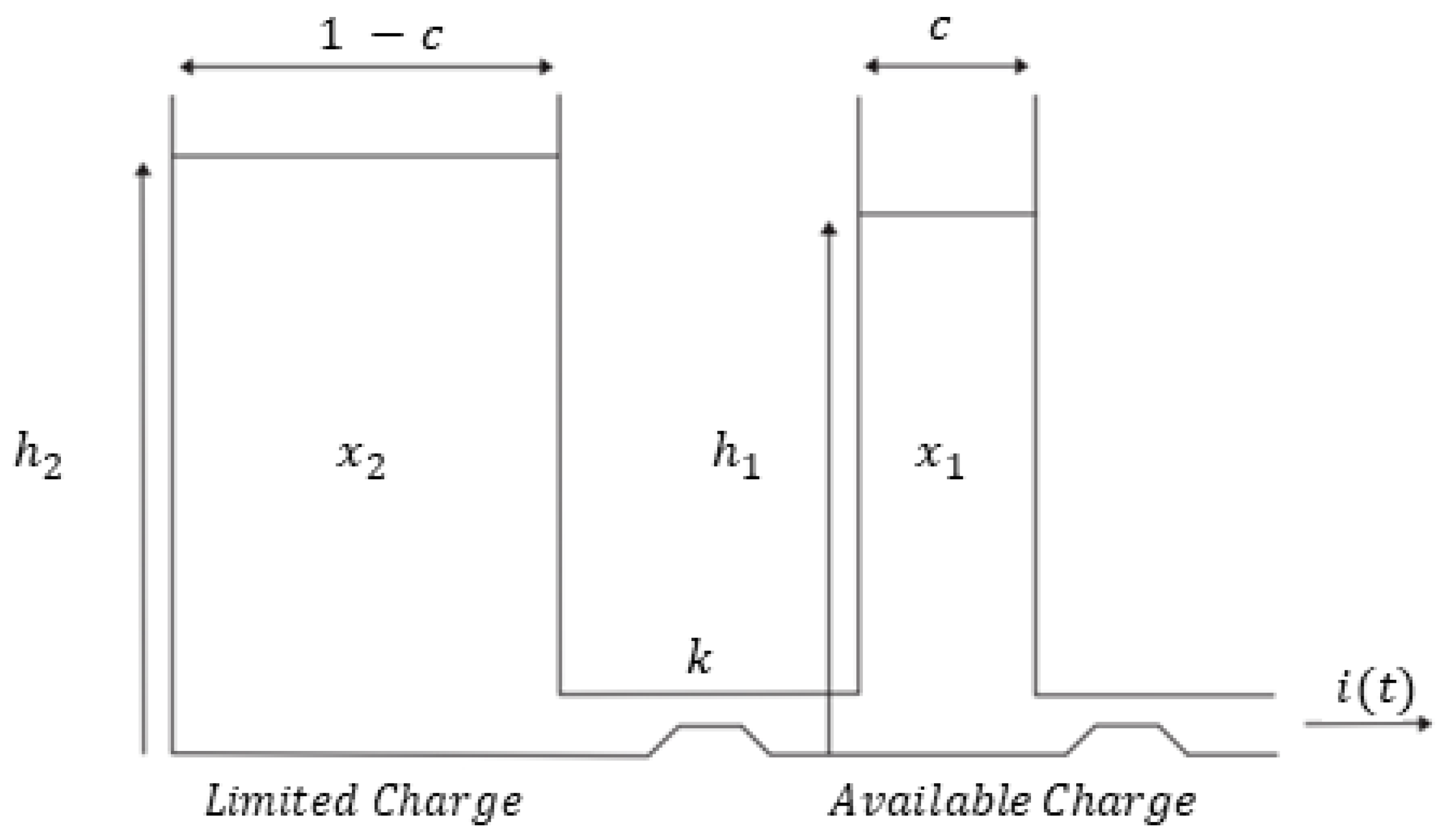
30], the principle of this model consists of two tanks, in which one contains the available charge or that available for the conversion of energy into Direct Current (DC), and the other tank contains the unlimited charge or that which is chemically connected, but unavailable for use. The diagram of the models with the tanks is illustrated in
Figure 1, in which, they are presented in all different dimensions. In this figure, a fraction
c of the total capacity is observed, which represents the available charge (
), and the other fraction 1 −
c represents the limited charge (
). The chemical process starts with the tank, which holds the available charge, supplying electrons to the load
i(
t), while the tank, which holds the limited charge supplies electrons to the tank of available charge. The parameter
k is responsible for the flow from the limited load tank to the available load tank. For calculation purposes, it is considered that
i(
t) =
I, which means, constant current.
It is also important to mention the calculation of the life of the battery bank, expressed in years, from
where
is the number of batteries,
the life rate of a single battery,
the annual transfer rate (the total amount of energy that travels through the bank of batteries in a year) and
is the battery life (the maximum life, regardless of performance) [
31].
Some references make extensive use of system modeling (ESS integrated with PVs), in which one of them uses the Maximum Power Point Tracking (MPPT) technique. This PV configuration with an ESS uses DC-DC and DC-AC controllers, necessary for different scenarios to be visualized, such as changing irradiation levels at a fixed load and load variation at a given irradiation value to observe the control response of the system [
32].
Another example of a study is on the energy transfer mechanism, aiming at the automatic energy balance of submodules of a modular multilevel converter. Thus, experimental results are analyzed from several necessary inputs for this new topology and consequently a great associated performance [
33].
3. Review of Cases
In this section, some case studies of stations are presented charging electric vehicles associated with an energy storage system using batteries and renewable energy. The first case is a technical report carried out by the IEC that shows different configurations of charging stations, with variations both in installed power and in type connection to the interconnection bus [
34]. The second case features a charging station with this integration enabled, also be used to provide ancillary services [
35]. In the third case, the impact of charging electric vehicles is shown, and energy storage systems in batteries in the photovoltaic hosting capacity of low voltage distribution grids [
36]. Finally, the last case presents an installation at the University of California, where a microgrid is created, showing applications that can be carried out by BESS in this system, such as power shift, power smoothing, or demand control [
37]. The article presented here aims to show in detail the quality criteria of energy with the installation of a system with these characteristics, showing the advantages and impacts of using BESS.
3.1. Case 1: Study of PV–EES–EV Charging Station Based on Common AC Bus, IEC TR 62933–200:2021 [34]
In the case study presented in the document PD IEC TR 62933–200:2021, various types of configurations of solutions containing photovoltaic systems, storage systems, and charging stations are shown. In this document, the storage systems are highlighted as they represent an option to make charging stations friendly to the electrical grid, improve clean energy self-consumption, and increase the revenues of the charging stations. Additionally, the differences between the configurations considering common DC bus connections among the systems, and common AC bus connections are also shown. What sets this study apart from this article is that while the study places a greater emphasis on the applications of the storage system, this article presents in detail the energy quality criteria when using storage systems in conjunction with charging stations, and also differentiates based on the type of technology used in the batteries, specifically lead-carbon (Pb–C). For the case of a structure with a common AC bus, the applications used in the system are power smoothing, load shifting, and energy arbitrage. The use of each of these applications is divided throughout the day in a way that they are utilized as much as possible, bringing better performance to the system. Finally, at the end of the study (PD IEC), the document presents operation recommendations for the storage system, depending on the use of the solution and the relationship between the BESS capacity, the charging demand, and the photovoltaic system.
3.2. Case 2: Power Management Analysis of a Photovoltaic and Battery Energy Storage-Based Smart Electrical Car Park Providing Ancillary Grid Services [35]
The paper talks about how future parking lots will require a lot of power to support electric vehicle (EV) charging, as there will be both an increase in the penetration of EVs and a higher demand for charging power as battery packs increase in capacity. Effective management of charging and local battery storage can be installed to help prevent excessive increases in electrical feeder capacity; however, parking lots will inevitably attain significant power capability in the future. There is therefore an opportunity for parking lot owners to utilize this and generate additional revenue by providing frequency response services to the electrical grid. This paper describes the modeling of a parking lot that utilizes photovoltaic power generation, battery storage, and EV charging management strategies to provide a grid frequency response service. The analysis using simulated parking lot data shows that it can provide high availability in terms of service but it is dependent on the capacity of the installed generation and storage.
3.3. Case 3: Analyzing the Impact of EV and BESS Deployment on PV Hosting Capacity of Distribution Networks [36]
This article analyzes the impact of charging electric vehicles and battery energy storage systems on the photovoltaic hosting capacity of low-voltage distribution networks. A Monte Carlo-based simulation is used to analyze predominantly rural, intermediate, and predominantly urban residential regions facing different penetrations of electric vehicles utilizing uncontrolled and controlled charging, and evaluate their impact on photovoltaic hosting capacity. Subsequently, electric vehicles are replaced or supplemented by residential battery energy storage systems, and their combined impact on the hosting capacity is studied. The results revealed that electric vehicles alone do not improve the hosting capacity unless they are connected to the network during sunshine hours. However, controlled storage provides a remarkable increase to the hosting capacity and exceptional contribution in combination with electric vehicles and customers with high loads. Finally, a feasibility analysis showed that controlled charging of the storage has a lower marginal cost of increasing hosting capacity as compared to network reinforcement.
3.4. Case 4: California University [37]
The “Irvine Smart Grid Demonstration” project was led by the Advanced Power and Energy Program at the University of California with the aim of understanding and proposing methods to mitigate the negative impacts of the integration of electric vehicles (EVs) into electrical networks. The experimental platform, called Car Shade, consists of a public charging station with 20 chargers connected to the university’s microgrid and installed in a parking lot, in addition to alternative energy sources such as a 48 kW photovoltaic plant and a 100 kW/100 kWh battery storage system. The system is connected to the microgrid through a transformer and has control algorithms for demand response, grid energy displacement, power smoothing, and charger feeding. The results showed that the system was able to allow for high photovoltaic generation penetration, successfully displace grid energy and contribute 80% to the charging of electric vehicles and 89% in the total inserted.
3.5. Relationship between Presented Cases and Tested Solution
Through the studies of the solutions below, it is possible to see the benefits that this type of installation brings to the electrical system, promoting everything from reducing carbon emissions into the atmosphere to reducing costs linked to energy consumption and improving the reliability of the network. Each study presents its specificities, focusing on the verification of possible applications for the solution, such as acting in ancillary services, or better use of the energy generated by photovoltaic systems.
Comparing them with the study presented here, there is initially a considerable difference in the technology used in the battery since the solution uses lead-carbon batteries. In addition, in some cases, only simulation results are presented, while the analysis in this article presents experimental results, obtained in the laboratory of real application cases, showing a solution behaving in a real situation, presented from the control system in the flow of energy among the sources of power generation. In the present study, the control system is also applied primarily in the supply of renewable energy, in this case, photovoltaics. In addition, the work also emphasizes the power quality criteria required by local standards, presenting comparative data that prove such behavior or that is not observed in studies in the literature.
An important point to be taken into account is that comparing the solution used in this work with the IEC standard presented in case 1, it is noted that the suggested applications for configuring the solution in the article are correctly placed, namely: energy displacement, demand control, voltage control, and ancillary services.
4. Methods and Materials: Overview of System
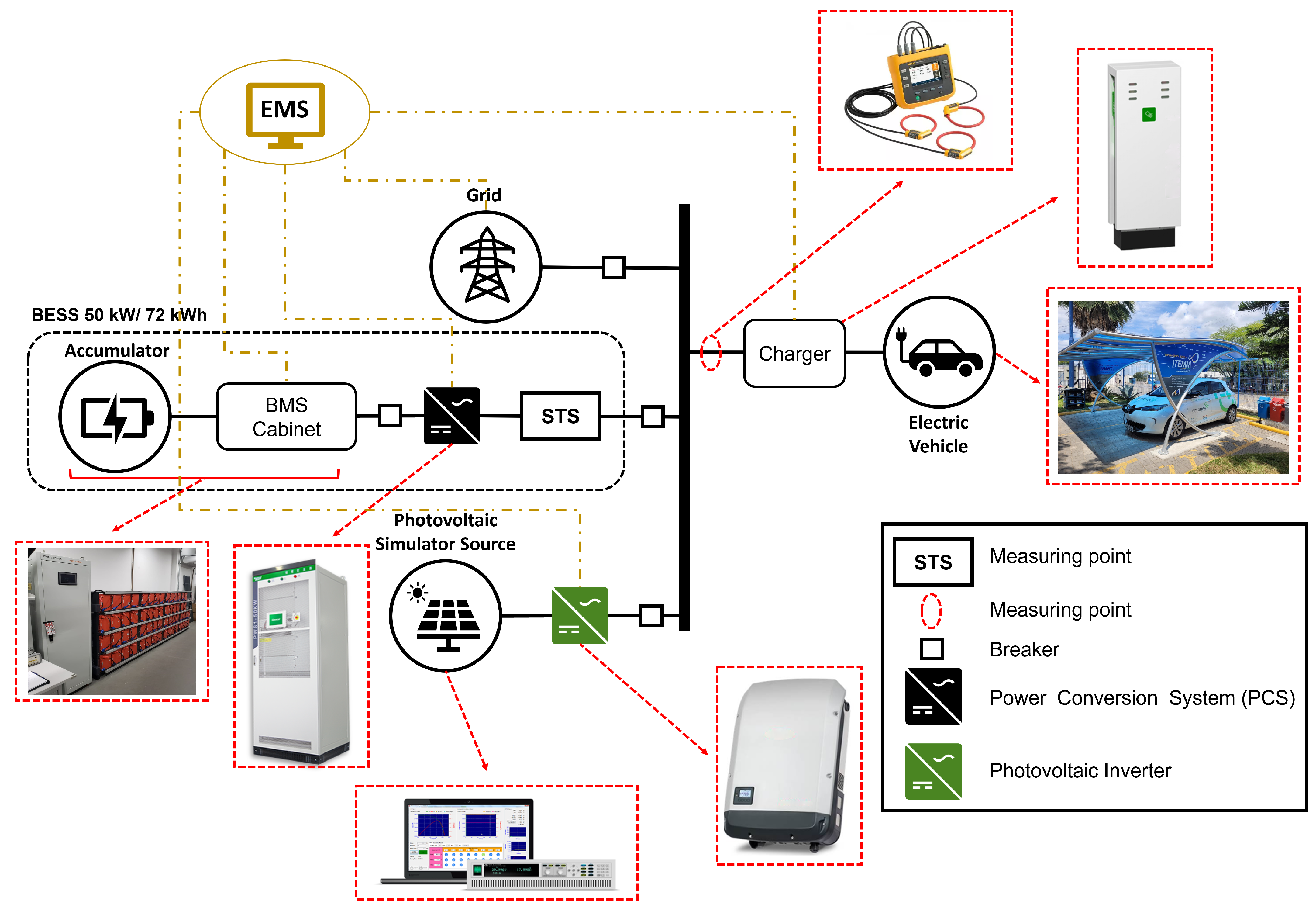
This section describes the components that make up the system: BESS, PV system, and charging system. The components that make up the charging station are adjusted and connected to an AC bus, the connection diagram is shown in
Figure 2.
The basic element of BESS is the battery, which is responsible for storing chemical energy and making it available, when necessary, in the form of electrical energy. At BESS, the battery bank is composed of multiple electrochemical cells connected in modules, in which the cell technology to be used in the bank is defined based on the application and its requirements. The storage system is used to store surplus or unused energy generated by the PV system. This energy, which is stored in the batteries, can be used both for recharging EVs and for use in specific BESS applications that improve the system’s energy quality and stability. These applications vary according to the user’s need and can be: backup, demand control, energy arbitrage, voltage regulation, and power factor correction.
BESS batteries are lead–carbon and have a rated voltage of 12 V and a rated capacity of 100 Ah each. Accumulators are connected in series, thus totaling a voltage and a nominal capacity of 720 V and 100 Ah, respectively.
Table 1 presents the BESS battery information, which is essential to define the safety and operation limits of BESS, to maintain the efficiency of the batteries through the Battery Management System (BMS).
To complement the system and to allow for variations in demand load, a resistive load bank can also be used in the system (
Figure 2). The bank has a rated power of 30 kW, allowing different load arrangements, such as 1 kW and 4 kW.
Table 1 includes its specification.
The photovoltaic system consists of the integration of a DC source capable of simulating photovoltaic arrays, in series with a real photovoltaic inverter to perform the conversion of DC power to AC power, so that the energy can be injected into the AC bus.
The charger has two Type 2 sockets and variable power ratings between 3.7 kW and 22 kW at each socket. Among the features of the equipment, one of them is the possibility of adjusting the value of the current supplied by the charger to the connected electric vehicle, to control the energy between the two outlets.
This component allows the actual charging of the vehicle in the proposed system, aiming to evaluate the benefits and limitations of the solution in the project. The vehicle can be charged by either single-phase or three-phase chargers. In the system, the charger has three phases and it is estimated that it will be able to recharge up to 80% of the vehicle’s battery in 1 h. To go into more detail about the car’s rated characteristics,
Table 1 shows the necessary information. The electric vehicle used for the tests is shown in
Figure 2.
The technical specifications of recharge station components are shown in
Table 1. All the recharge station equipment is commercial.
Control Strategy
The Energy Management System (EMS) is responsible for monitoring and managing the equipment that interacts with the BESS controls its power flow and, in this way, enables charging/discharging of the storage system at the most opportune times possible. Considering the EV charging station that BESS will compose, the control strategy used must prioritize the supply of energy to the load, optimize the PV generation and minimize the use of the electrical grid. Thus, for an effective and efficient operation of the charging station, the strategy must:
Prioritize the supply of the load, regardless of the energy source used;
Use the PV system to recharge EVs and BESS;
Use the PV system and BESS whenever possible to supply demand.
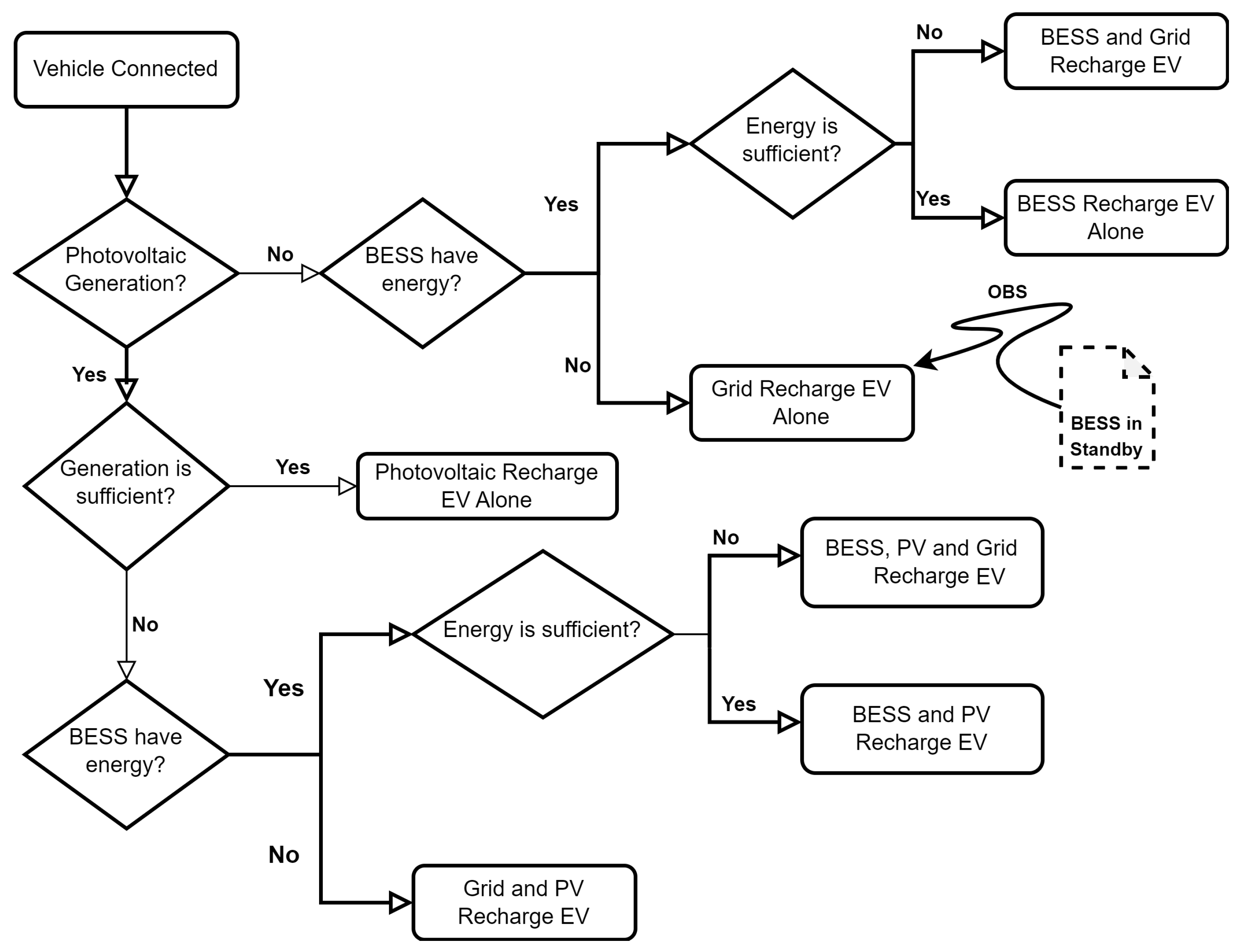
The fluxogram is presented in
Figure 3. In it, it is possible to observe that the supply priority is the renewable energy generation system, the first verification being carried out, with the verification of the amount of energy that is being generated by it and later doing the analysis of the integration with the other components coupled to the bus.
Therefore, the EMS must continually analyze the presence of load at the station and where applicable, the station must:
Use the PV system to supply the load;
Use BESS whenever PV generation is not sufficient or not available to supply the load;
Use the electrical grid to meet the load.
However, when there is no load, you must:
Use the PV system to recharge the BESS if the storage system does not is fully charged;
Use the PV system to inject into the electricity grid if the storage system is fully charged;
Depending on the time and the state of charge of the BESS, use the electrical grid to reload BESS.
It should be noted that, given that the purpose of the control strategy is to minimize the use of the electrical grid, whenever there is a load at the station, BESS should never be recharged by the electricity grid so that there is no simultaneous charging of BESS and EVs.
The power flow control is divided in a macro way into three possible scenarios, which can be, in Case 1, the system has no load; in Case 2, there is load and PV generation; and in Case 3, there is load, but no PV generation.
In case 1, the off-peak period (cheaper grid energy) is used to recharge the BESS until its state of charge reaches . If BESS is fully recharged or the period in question is the peak, BESS remains on standby, without recharging or discharging. BESS can be recharged either by the grid or by PV, depending on the source available at the time. For case 2, the PV generation can completely supply the load, and the excess power is used to recharge the BESS when the storage system is not fully recharged. If the load is not served by the PV, the power deficit is provided by the BESS or the grid, depending on the pricing at the time in question. Finally, in case 3, the load is supplied by BESS, at a time when there is peak pricing and BESS has a load higher than the or it may be at a time when there is off-peak pricing, a contracted demand lower than the power required by the load and the BESS is higher than the , respectively.
5. Results
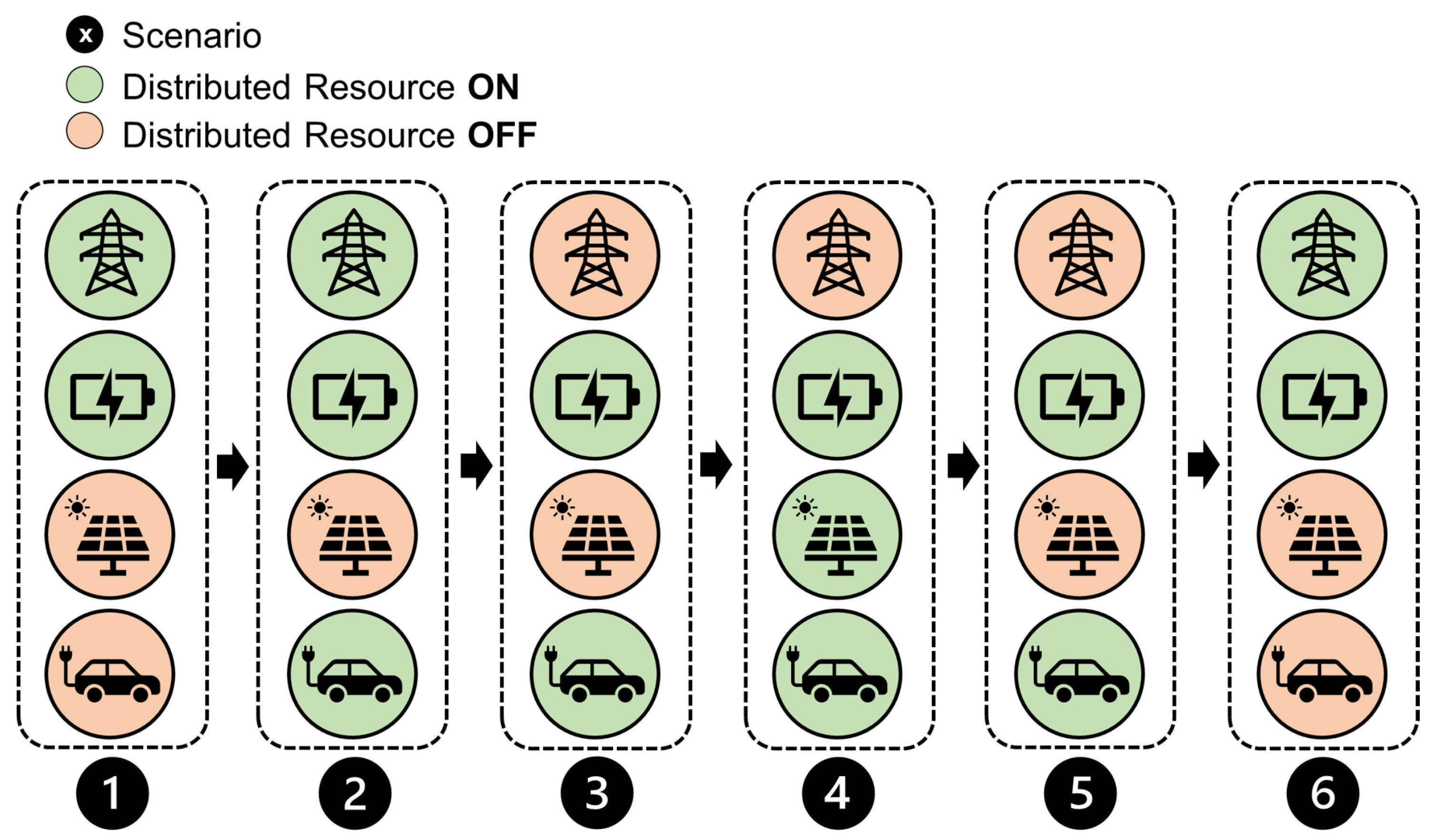
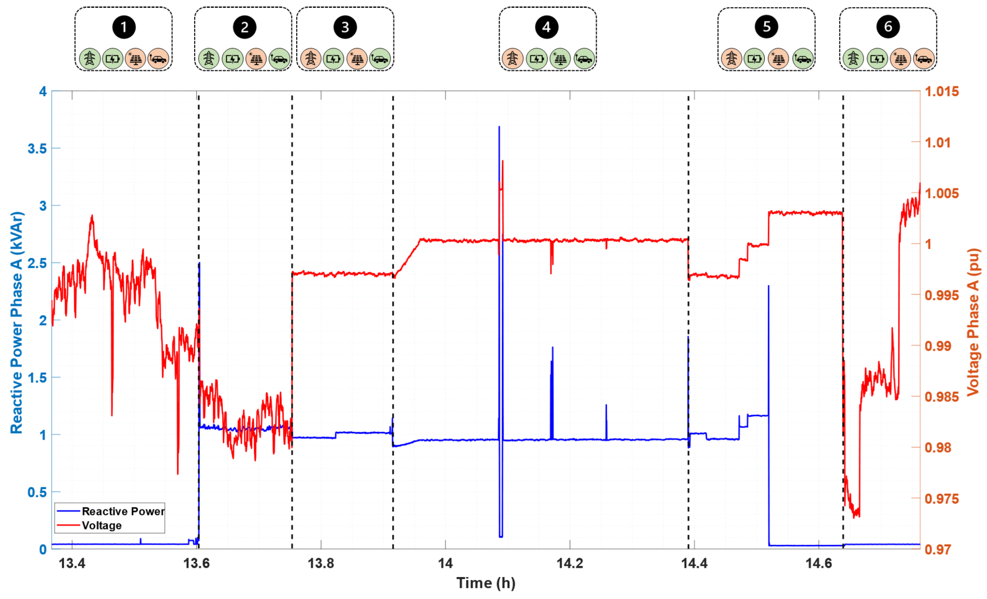
In a real operating situation, a system composed of BESS, main power grid, photovoltaic system, and electric vehicle, runs through possibilities of operation combinations. In this regard, the analyzes carried out were based on six possibilities of recharge configuration that are distinguished as shown in
Figure 4. In this article, each configuration is considered as a recharge mode. In this way, it can be seen that in Mode 1, there is a joint operation of BESS and the main electrical grid; in Mode 2, there is a joint operation of BESS, the main electrical grid, and EV; in Mode 3, there is a joint operation of BESS and EV; in Mode 4, there is a joint operation of BESS, photovoltaic system and EV; in Mode 5, there is a joint operation of BESS and EV; in Mode 6, there is the return of joint operation of BESS and the main electrical grid. Thus, we sought to observe the occurrence of variations in the magnitudes of voltage, frequency, current and harmonic distortion in each mode under analysis.
To demonstrate the results of the electrical energy quality analysis, it is worth mentioning that the data acquisitions were carried out at the common coupling point, through the installation of the energy analyzer. The times of scenario changes during the recharge period were recorded and can be observed according to
Table 2. Note that the most critical scenario is during scenario “4”, where the power flow is being provided by the BESS and the photovoltaic system, operating in off-grid mode, demonstrating the efficient performance of the system’s EMS since the photovoltaic assumes all the energy supply that is being produced by it, leaving only the remainder to be provided by the BESS, in addition, variations are performed in the power of the photovoltaic system to simulate the occurrence of shading, demonstrating the positive impact of the installation of the photovoltaic system storage in the solution, as it is responsible for injecting or absorbing power at certain times to ensure system stability.
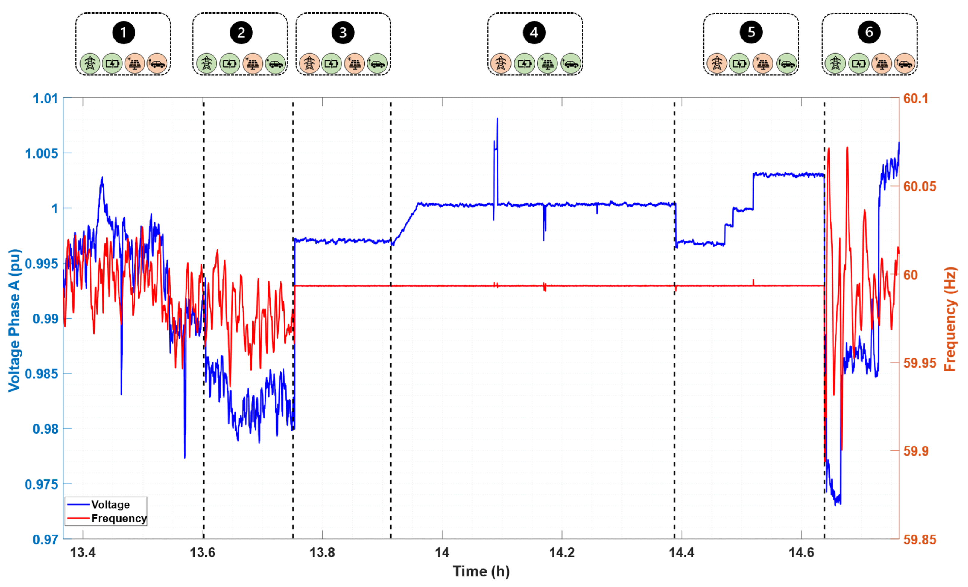
One of the comparisons to be taken into consideration when analyzing the quality criteria of the energy solution is related to the verification of voltage behavior concerning frequency. Through
Figure 5, it is observed that in all modes, the voltage and frequency remain within the values established by the standard that governs the quality criteria for energy in Brazil, PRODIST—Module 8 [
38], being with the maximum, minimum and average values as presented in
Table 3, this comparison method is also used and presented in the article [
39].
Addressing the criteria for each of the modes for
Figure 5, in mode 1, the BESS is in standby in parallel with the grid, at this moment, the grid is the voltage and frequency reference for the system. In mode 2, the BESS remains on standby, but at this moment the electric vehicle is connected to the charging station, starting the charging process with energy supply only by the grid, at the moment of this load entry, a voltage drop is observed due to the power requested for battery charging, it is worth noting that with the entry of several vehicles at the same time, this drop may be greater, causing disturbances to the system. In mode 3, where the BESS enters the energy supply, operating as a v–f reference, we notice a significant improvement in the voltage levels, reaching values very close to 1 p.u and with significant stability in the level; in this mode, the system’s ‘backup’ application is emphasized, which is used when there is an interruption of energy supply by the grid and the BESS takes over this supply.
In mode 4 of the charging operation, the photovoltaic is observed entering operation, following the control criterion, observed in the Flowchart of
Figure 3, the photovoltaic will assume the power supply required by the charger to the level that is being generated by it, the addition of a generation source causes the voltage has a small increase in value. Still, in mode 4, it is possible to observe sudden variations in voltage, this behavior is performed intentionally to verify the system’s behavior in the face of variations in photovoltaic energy generation, and as desired, the system continues to operate normally, maintaining frequency practically constant and without large variations. For mode 5, the photovoltaic system stops generating energy, then the BESS starts to supply power for charging alone again, this mode is characterized by the arrival of the end of the vehicle charging process, being observed after a period of the increase of voltage, which is justified by the decrease of the power required by the vehicle since the battery charging acceptance is already decreasing. Finally, in mode 6 the vehicle charging is terminated, in this operating mode, the grid returns to the system, returning to the v–f reference, noting the return in frequency oscillation, with a greater oscillation at the moment when the grid is still entering into synchronization.
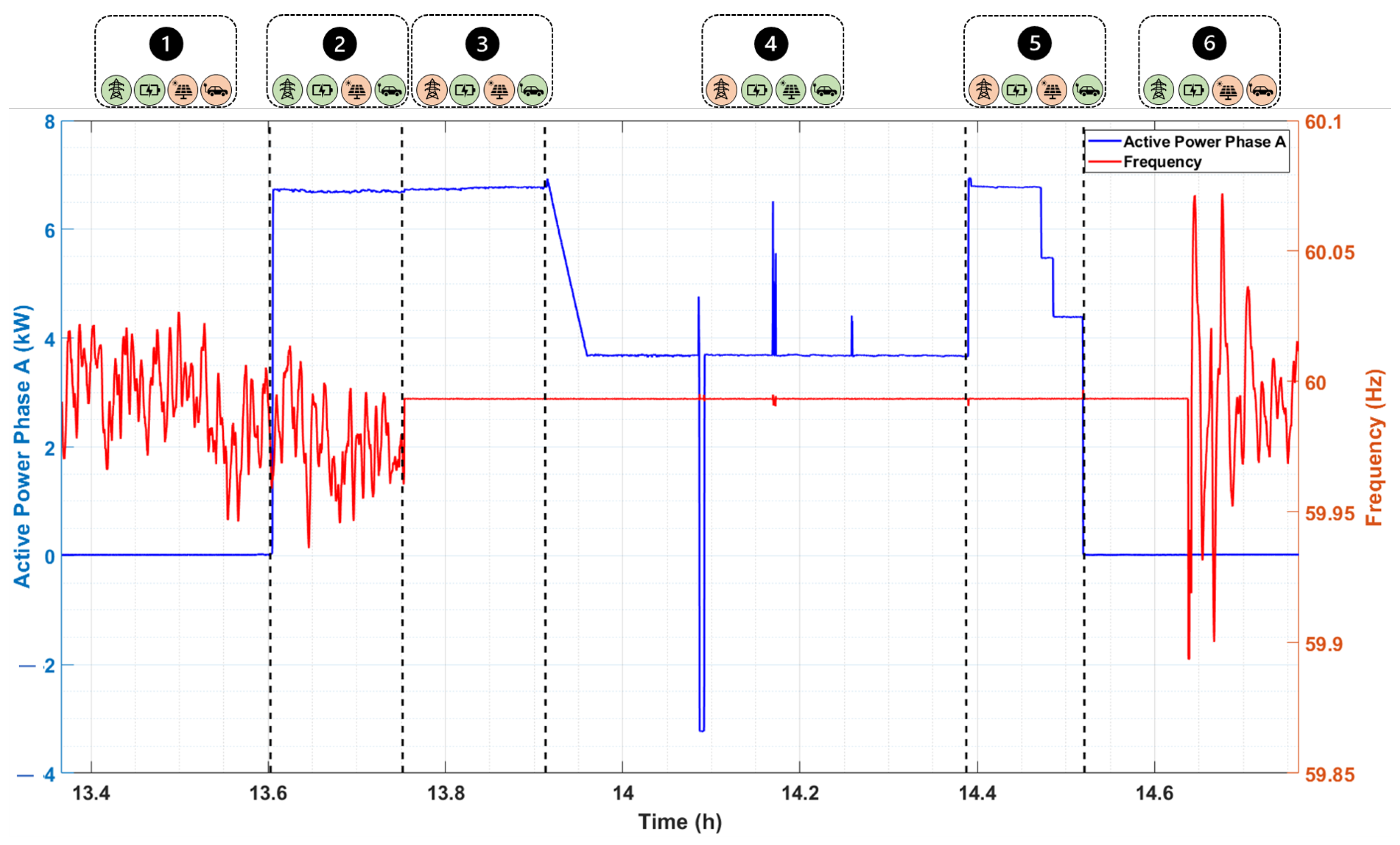
Through
Figure 6, the active power and frequency graphs are presented. It is noted that the active power supply only occurs from mode 2 when the electric vehicle is connected to the charging station. Note that initially, the power supplied to the vehicle is approximately 6.7 kW per phase (three-phase system), totaling a power of 20.1 kW, close to the nominal power value of the vehicle (22 kW). In mode 3, with the exit of the grid and the transfer of supply to the BESS, the power supplied to the vehicle remains the same, and the load does not observe the transition of the generator at any time. In mode 4, there is a reduction in the power supplied by the BESS, since the photovoltaic system assumes part of the power required for charging. Furthermore, in this mode 4, it is possible to notice at the times of intentional power variations of the photovoltaic, that the BESS plays a role in not allowing the system to lose its control, at certain moments absorbing active power, and at certain moments providing active power. For mode 5, it is noted that active power has a reduction at the moment when the vehicle charging is ending, this is justified by the already mentioned reason, the battery charging acceptance decreases, reducing the required power. Finally, in mode 6, the total charging ends with the supplied power being equal to zero.
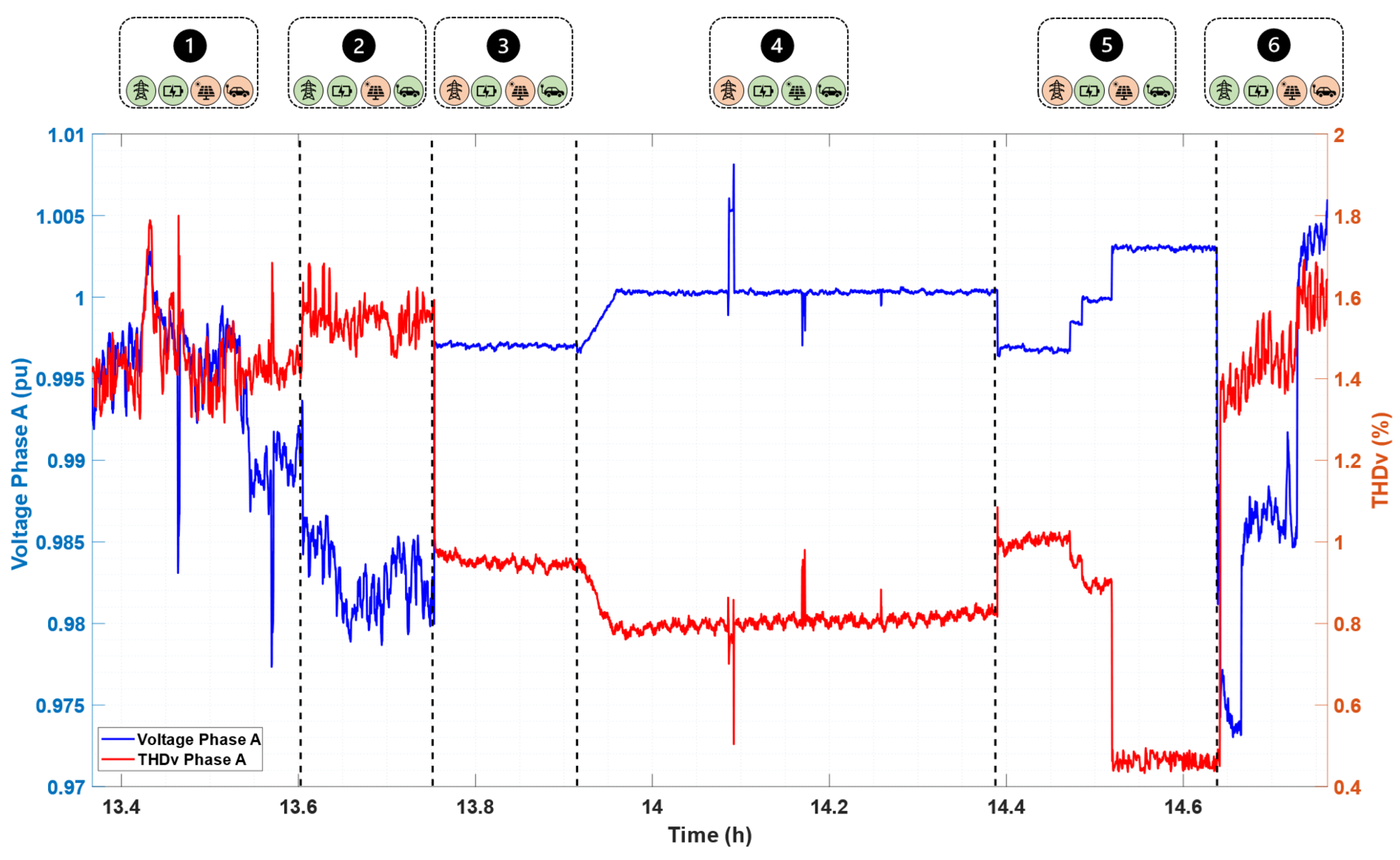
Figure 7 shows the behavior of the harmonic distortion rate of voltage (THDv) about voltage. It is noted that in all modes, the voltage remains with a value well below that stipulated by the standard (PRODIST Module 8), which is less than 10% for voltages less than 1 kV. The entry of BESS promotes a reduction in the value of distortion, passing from a value around 1% to 0.98%. If we pay attention to mode 4, we will also notice that the entry of photovoltaics as a source of energy generation, brings further reduction in distortion. In mode 5 the harmonic distortion of voltage decreases even more once the electric vehicle charging is coming to an end and the power request is also decreasing. Finally, in mode 6, the distortion returns to the values of mode 1 once the grid returns to be voltage reference.
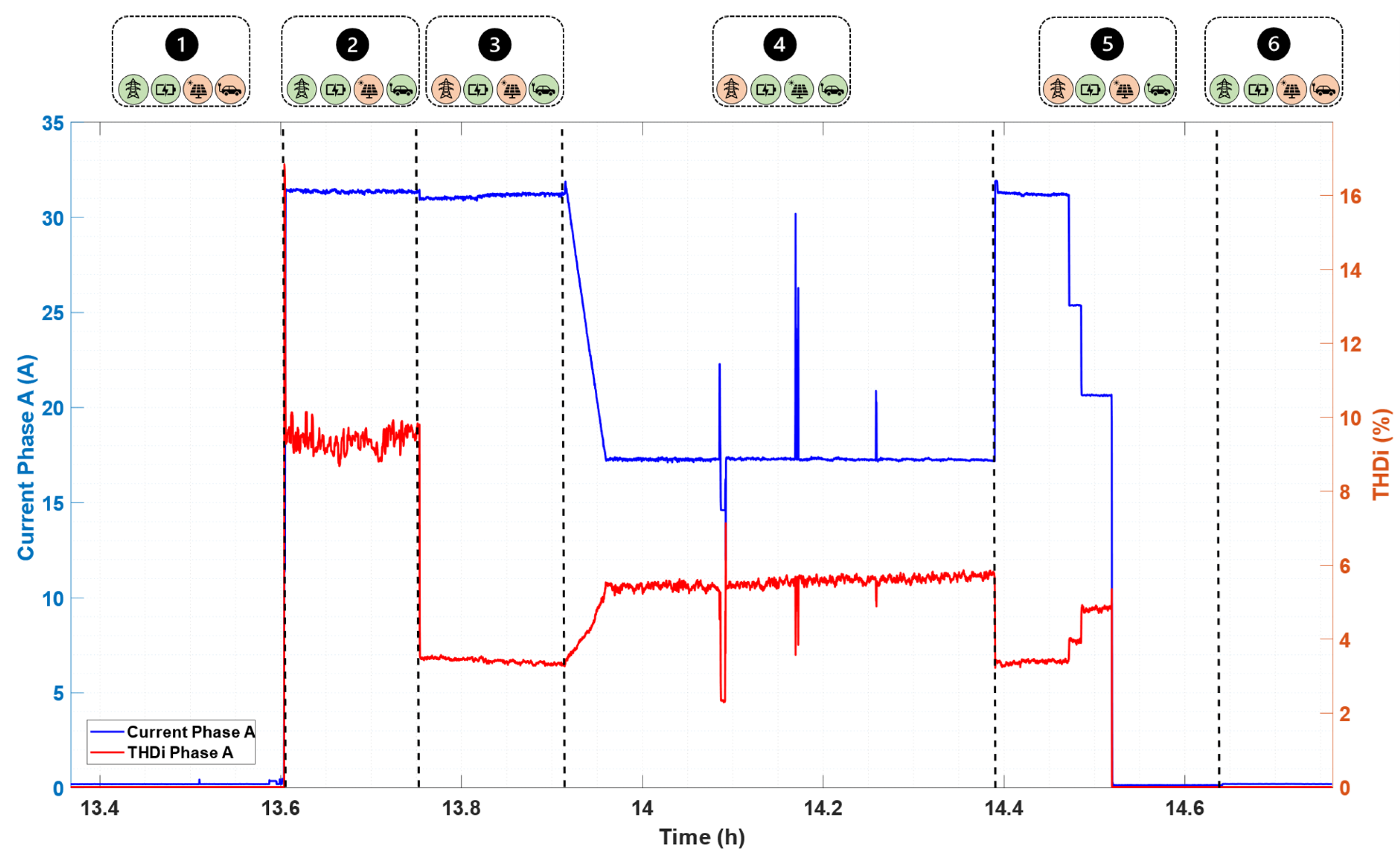
In
Figure 8, the relationship of phase current with harmonic distortion rate is presented. Some relevant points should be taken into consideration when analyzing these energy quality criteria, in mode 2, for example, at the moment when the BESS is on standby, the vehicle is connected and starts to be recharged by the grid, a distortion of around 18% is observed, but when comparing the distortion with mode 3, in which the BESS begins to act as a voltage reference, the distortion rate decreases significantly, dropping to values around 7%. Additionally, it is noted in mode 4 that the insertion of the photovoltaic system into the system causes an increase in the distortion rate, and in mode 5 this distortion reduces to levels that were seen in mode 3 since the photovoltaic stops generating energy.
About reactive power, through
Figure 9 a small portion of the terms is noticed at the entrance of the load at the charging station, something around 1 kvar per phase. A relevant point to be noted in this Figure is in mode 4, characterized by the absorption of reactive power at the moment when the voltage has an elevation, and the injection of reactive power at the moment when there is a voltage drop, highlighting another application of the BESS which is voltage control.
A very important analysis that must still be considered concerns the rates of voltage imbalance between phases in each of the scenarios presented, these values are given in percentage and must be below 3% according to the national electric energy agency. The rates of imbalance for each of the scenarios are presented in
Table 4.
Note that, in modes where charging is done exclusively by the storage system or together with the photovoltaic system, the voltage imbalance is reduced considerably.
7. Conclusions
Through the results presented in this report, a technical analysis of the operation of an electric vehicle charging station was carried out through tests in the practical system installed in the city of Belo Jardim, PE, Brazil. With this, it is possible to have an idea of the behavior and impact of the installation on the electrical grid. It is possible to analyze the vehicle charging process, as well as the interaction between the system devices: BESS, photovoltaic, and chargers.
Thus, the article presented the current scenario of the growth of charging stations for electric vehicles, bringing evidence of the use of the BESS configuration and photovoltaic system to meet the demand for electric vehicles. In this configuration, it is possible to observe that the electrical network is a resource that is sought to be used as little as possible, and, when the system operates connected to the main electrical network, its energy quality is consistent with the current quality standard, as established in PRODIST module 8. In addition, there are several advantages in the introduction of BESS in this architecture, as in addition to offering improvements in energy quality during off-grid operation, the electric vehicle gains a second power source from the batteries, offering increased reliability for the developed system.
Four cases correlated with the one studied in this article were addressed, to ratify the originality of the study due to the use of lead-carbon batteries as an alternative capable of subsidizing the practical implementation of the solution. Lead-carbon batteries are based on a highly mature technology in the market for stationary applications (derived from lead-acid batteries) and have high recyclability, non-explosive chemistry, and partial charge operation, and are viable for quick recharges.
In this regard, the study presented a control strategy that prioritizes the supply of the load through a photovoltaic system and the use of the combination of BESS and PV systems, when available, to meet the load demand. In this architecture, the electrical network is little used, which makes the power supply of the electric vehicle as renewable as possible. To explore the versatility of the solution, six real operating scenarios were developed.
An analysis of electrical power quality was presented. With the results, it is possible to observe that the insertion of the electric vehicle in the grid did not cause significant impacts on the quality of electric energy. The voltage remained within the values established as acceptable by the National Electric Energy Agency—ANEEL (0.92 p.u and 1.05 p.u), as well as the harmonic voltage distortion rates (less than 10%), were also within the limit values. Furthermore, significant frequency variations (between 60.1 Hz and 59.9 Hz) are not noticed during the insertion of the photovoltaic system. The correct functioning of the power flow of the solution was seen (BESS + photovoltaic system + electric charger + grid).
In addition, the values of unbalance between the phases were obtained during each recharge mode presented, noting that the recharging of vehicles only by BESS causes this imbalance to be reduced. Finally, analyses of the quality of electricity were carried out for each of the scenarios that occurred in a recharge process, these analyzes were carried out from the data obtained through the energy analyzers, and each of the figures of merit was seen differently, isolated for each scenario and its main considerations based on national and international standards are exposed in the article.
