Abstract
The use of combined heat and power (CHP) systems has recently increased due to their high combined efficiency and low emissions. Using CHP systems in behind-the-meter applications, however, can introduce some challenges. Firstly, the CHP system must operate in load-following mode to prevent power export to the grid. Secondly, if the load drops below a predefined threshold, the engine will operate at a lower temperature and hence lower efficiency, as the fuel is only half-burnt, creating significant emissions. The aforementioned issues may be solved by combining CHP with a battery energy storage system (BESS); however, the dispatch of CHP and BESS must be optimised. Offline optimisation methods based on load prediction will not prevent power export to the grid due to prediction errors. Therefore, this paper proposes a real-time Energy Management System (EMS) using a combination of Long Short-Term Memory (LSTM) neural networks, Mixed Integer Linear Programming (MILP), and Receding Horizon (RH) control strategy. The RH control strategy is suggested to reduce the impact of prediction errors and enable real-time implementation of the EMS exploiting actual generation and demand data on the day. Simulation results show that the proposed method can prevent power export to the grid and reduce the operational cost by 8.75% compared to the offline method.
1. Introduction
The importance of efficient and sustainable energy production is growing as a result of the increased global demand for energy and growing concerns about the accelerating effects of greenhouse gases. The actions toward lowering greenhouse gas emissions have led to an increasing emphasis on boosting energy efficiency. Thus, distributed generation is supported primarily through the use of CHP systems [1]. A CHP system simultaneously generates electricity and usable heat from a single fuel source. Thus, many CHP units that are compact and powered by internal combustion engines can supply quick balancing energy owing to excellent dynamic behaviour and simultaneous heat for heat loads, such as residential, industrial, and commercial buildings [2]. CHP is a technology that offers excellent primary energy savings and, consequently, lowers CO2 emissions; this technology was identified as one of the options for attaining the primary energy-saving targets of the European Union [3]. CHP units achieve cost advantages due to energy savings (electricity produced that would otherwise have been imported from the grid) and heat savings (heat generated that would otherwise have been supplied by on-site gas-fired boilers). The installation, maintenance, and fuel costs must all be addressed when determining the economic feasibility of CHP units.
The maintenance and fuel input expenses make up the CHP units’ operational costs. Typically, the output from a CHP unit is roughly 40% electricity and 60% heat, with electrical efficiencies ranging from 35% to 45% and 85–90% total efficiency. A typical CHP system will convert about 90% of the fuel into energy [4]. Therefore, it is vital to verify whether the CHP sizing is based on electrical or thermal demand. In this paper, the CHP is sized based on the electrical load demand; therefore, it is electrically led.
When compared to the utilisation of conventional methods for the delivery of energy, such as diesel generators, the consumption of fuel by a CHP system is reduced by approximately 35% [5]. However, even in the best-case scenario, cogeneration systems would still incur losses if the demand was lower than the supply. In energy management, striking a healthy equilibrium between the supply of energy and the demand from end users has been a challenge for a long time. It is difficult to keep up with changing demand, which makes it challenging to match supply to demand. It is common knowledge that energy storage has the potential to help bridge the gap that exists between supply and demand. Existing CHP systems may be supplied with thermal storage but seldom with electrical storage, even though electrical storage may also provide significant benefits [6]. The inclusion of these energy storage facilities will not only increase the flexibility and overall efficiency of a CHP system but will also enable the decoupling of energy output and demand, enabling surplus energy production to be stored and utilised when more energy is necessary [6]. When the BESS is full, extra power might be sold to the grid if the network operator permits it. It is advised not to use the CHP at less than 50% of its capacity for it to function properly. This is due to the possibility that continuous operation in low-load mode could result in higher gas consumption and, as a result, a significant buildup of carbonised oil, or oil residue, in the engine, the suction, and the exhaust system [7]. This residue would reduce the engine’s effectiveness and dependability, increasing maintenance costs. Usually, operating uninterruptedly under low-load mode can lead to ignition problems, increased lubricant oil consumption, and fuel dilution [8]. The emergence and persistence of residue negatively impact the functional behaviour and the engine’s lifetime. In addition, when a conventional engine is operating in low-load mode, it cools down. Due to the low temperature in the chamber, the fuel is partially burned, producing white smoke with high hydrocarbon emissions. The percentage of unburned fuel caused incomplete combustion and poor engine performance [7,9].
In light of these limitations in running a CHP system that is connected to the grid, numerical optimisation can be utilised to improve the efficiency of their operation. Optimising the operation of a grid-connected CHP system has been the subject of a number of studies, which has led to the development of a variety of potential solutions. The primary limitation is meeting the local heat demand at all times due to the impossibility of transporting heat over long distances. In this way, the system’s economic dispatch aims to minimise the fuel costs of the CHP units [10,11]. Maleki et al. [12] developed a combined heat and power (CHP) system that can sell its surplus energy to the grid at the Feed-in Tariff rate (FIT). However, the energy market agreements upon which this strategy is based are not always in the best interest of the microgrid owner or operator. Xie et al. [13] Using the mass balance and energy balance equations, presented a nonlinear dynamic model of a grid-connected CHP system that can successfully mimic thermoelectric interactions and then explore the effects of the CHP on the power grid. In order to maximise CHP systems’ efficiency and grid stability, this research is beneficial for designing new control strategies. In [14], an energy management strategy for the joint operation of CHP and PV prosumers inside a grid-connected microgrid is presented using a game theory approach. A Stackelberg-based optimisation model is developed, with the microgrid operator (MGO) as the leader and PV prosumers as the followers. The game’s characteristics are investigated, showing that the game has a unique Stackelberg equilibrium. The MG operators can allow the prosumers to use nonlinear constraint programming in order to achieve Stackelberg equilibrium. Verification of the model’s efficacy in calculating MGO pricing and optimising net load characteristics.
Recent advances have focused on system design, thermal analysis, and prime mover optimisation. However, technical solutions for the cost-effective dispatch of CHPs are still in the early stages of development [15,16]. In terms of the connection between the electrical load and the heat demand, there are few studies that analyse the economic dispatch of hybrid CHP systems with battery energy storage. Nazari-Heris et al. [15] present a research study on the short-term scheduling of an industrial heat and power microgrid that is linked to the grid and contains a fuel cell (FC), combined heat and power (CHP), boiler, battery storage system, and a heat buffer tank. The authors provided a solution to the multi-objective issue of microgrid dispatch by minimising cost and emissions while considering demand response programmes and uncertainties. For the purpose of overcoming the uncertainties in the optimal energy management of the microgrid for the optimal scheduling of the grid-connected system, a probabilistic framework that is based on a scenario method has been employed. This framework takes into consideration load demand and price signals. Economic analysis of energy storage is notoriously difficult due to the time-dependent nature of the technology. The future utility of a storage facility is contingent on the manner in which an individual facility is first managed. The indeterminacy of future events makes selecting the optimal storage procedure a challenging decision. Various methods exist for resolving the economic dispatch issue of CHP units with energy storage [16,17].
Deploying CHP systems in ‘behind-the-meter’ applications presents certain difficulties. Firstly, to avoid electricity being injected into the grid due to limits imposed by network operators, the CHP system must be configured to run in a load-following mode. Secondly, if the load drops to less than 50% of its nominal power, the CHP will have to be turned off, owing to the detrimental impact of operating gas engines at low power. Combining CHP systems with battery storage can address these concerns; nevertheless, the dispatch of CHP and battery power must be managed to optimise the overall operation, with all generated power being consumed on-site. In an offline day-ahead optimisation, previous knowledge of the electrical load is essential, and thus, it will rely on it as forecasted load data [18]. The prediction error is likely to produce suboptimal dispatch commands that might result in power being injected into the grid, violating the ‘behind-the-meter’ constraints. In practice, a power meter at the point of common coupling can be used to override the battery commands in real-time to prevent power from being fed into the grid.
This paper proposes a new online EMS for optimal economic operation of a hybrid (CHP and battery) grid-connected system for ‘behind-the-meter’ application. The objective is to minimise the operating costs of the hybrid CHP system while ensuring that power is not injected into the grid in the presence of changing electrical load demand. Rather than utilising the forecasted day-ahead electrical load, the optimiser runs online and performs load forecasting using long-short-term memory (LSTM) network and optimisation using mixed integer linear programming MILP considering a 24 h horizon. This is repeated every 30 min using the receding horizon (RH) strategy [19]. In the existing literature, the application of this combination of RH-based control using LSTM and MILP has not been previously considered for behind-the-meter applications.
The rest of the paper is organised as follows: Section 2 presents the model of the grid-connected CHP system. The problem is formulated in Section 3, and the energy management system implementation is presented in Section 4. Section 5 presents the simulation results with a detailed analysis, and the conclusion is drawn in Section 6.
2. System Description
The grid-connected CHP system under study is presented in Figure 1, with red dotted lines showing the communication link between the components of the microgrid and the EMS. It comprises two CHP units rated at 250 kWe connected to the grid, a 1000 kWh BESS, and a heat storage buffer tank. The present study considers the case of an animal feed processing factory that has both electrical and thermal energy requirements. The system is designed such that the electrical load is met by the combination of the electrical power generated from the two CHP units, power discharged from the BESS, and energy from the grid, while the recoverable heat from the CHP units and that from the tank should be equal to the heat demand at all times and any excess heat will be taken by the buffer tank and utilised when the heat generated by the CHP units is less than the heat demand or when the CHP units are out of operation. This is represented in Equations (1) and (2) below.
where, and are the electrical power generated by the CHP systems, is power discharged from the BESS, is the power utilised from the grid and , , , and are the recoverable heat from the CHP units, the heat demand, and heat stored in the buffer tanks respectively.
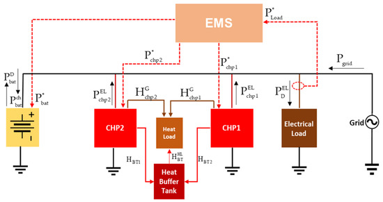
Figure 1.
Grid-connected CHP system with energy storage (CHP + BAT + GRID).
Up to two-thirds of the energy produced by conventional electricity generation is wasted in heat. The heat recovered from the system can be calculated using Equation (3) representing the relationship between the electrical power generated by the CHP system and the recoverable heat.
where is the total heat recovered from the CHP system and is the useful heat recovery rate.
The useful heat recovery rate shown in Equation (3) depends mainly on the fuel consumed by the prime mover and the fuel offset. Conversely, the fuel offset depends on the amount of useful heat recovery achieved by the CHP system, which measures the effectiveness with which the thermal energy is recovered from the prime mover and used to meet on-site thermal needs [20].
3. Problem Formulation
The problem formulation is based on the model shown in Figure 1. Since running the CHP generators at under 50% of their capacity is harmful, the scheduling problem will consider real-time demand uncertainties and ensure that the CHP generators operate within safety limits, as stated in the manufacturer’s datasheet [21].
Economic Operation of the Hybrid CHP System Using MILP
Economic dispatch, as part of unit commitment, represents the scheduling of generators to minimise the total operating cost, which can be cast as a constrained optimisation problem. The operation of the CHP system is very similar to that of the diesel generators, which have a nonlinear quadratic cost function, as seen in Equation (4).
where a, b, and c are the fuel cost coefficients and is the electrical power output (power generation) of the CHP unit.
This makes it difficult to solve its economic dispatch problem using linear programming. Thus, a piecewise linear approximation of the quadratic function is suggested to make the nonlinear quadratic cost function a MILP problem by approximating the nonlinear function as a series of straight-line segments [22,23], as shown in Figure 2.
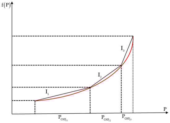
Figure 2.
Nonlinear cost function approximated by piecewise linear approximation.
The next formulation shows how the economic dispatch problem can be structured as a MILP problem. At first, the nonlinear cost function is expressed as a set of linear functions from a series of straight-line segments by approximating the operation using a piecewise-linear approach divided into three operating segments, as seen in Figure 2. The three segments of the CHP system are represented as with variables that represent the marginal production in each segment. Each segment will have a slope designated . The fuel cost is a function of the power dispatch of the CHP system and is the sum of the cost at plus the sum of the linearised cost for each segment which is the slope (i.e., the slope multiplied by the ) variable such as:
where is the sum of the linear cost function for each segment.
for and
The cost function is now made up of a linear expression in the three new optimisation variables as an update of Equation (8).
where is the number of CHP systems in the power system.
The MILP is then formulated to solve the economic dispatch problem to find the minimum operating cost while respecting the imposed constraints considering decision variables in Table 1.

Table 1.
MILP economic dispatch continuous and binary decision variables.
The equality constraints imply that the produced electricity and heat should be equal to the electricity demand and equal to the heat demand, and the heat stored in the heat buffer tank, as shown in Equations (9) and (2). The power imported from the grid is given by:
where is the power from the grid utilised by the electrical load and is the power from the grid used for charging the BESS. The BESS is charged with the power from the CHP units and the power from the grid .
The power from the BESS utilised by the electrical load is given in Equation (12).
The grid power and CHP power utilised by the BESS at any time should be greater than or equal to zero as:
The state of charge (SoC) is constrained by the minimum and maximum operating limits of the BESS.
where represents the BESS SoC state of charge. The inequality constraints for the BESS state of charge are given in Equations (15) and (16).
where represents the BESS capacity and is the coefficient associated with the physical features of the BESS and converts the BESS charge/discharge from its kW units to a percentage, and are the charge/discharge efficiencies of the BESS, respectively.
During the optimisation process, it is important that the charging and discharging of BESS are not scheduled simultaneously. Therefore, an inequality constraint for the ‘‘on’’ and ‘‘off’’ state of the BESS charge and discharge is formulated as an integer in Equation (17).
where and are binary variables representing the ‘‘on/off’’ and ‘‘off’’ states of the BESS charge and discharge, respectively. The inequality constraints for charging and discharging the BESS are shown in Equation (18).
The general objective function for the entire system is formulated as an economic dispatch problem in Equation (19).
Subject to Equations (1) and (9)–(18), where is the start-up cost of the CHP units, and are the cost of operating the CHP and the grid tariff, respectively.
4. EMS Implementation
The MILP optimisation-based EMS is suggested to be implemented in two ways: offline and online. Explanations of the two approaches are provided.
4.1. Offline Implementation
The offline version relies on data from the past and forecasts for the next day’s load. The above-described MILP optimisation requires a 24 h load profile as an input to be put into practice. Figure 3 depicts the results of a prediction made with a long short-term memory (LSTM) network, a type of RNN, to determine this profile. Next, the MILP optimiser receives the predicted data profile and uses it to formulate the dispatch commands for the battery and CHPs over the next 24 h. Then, in real-time, the predetermined dispatched commands are carried out. Inconsistencies with the optimisation constraints, such as the inadvertent injection of power into the grid, are expected due to the difference between the LSTM predicted load demand and actual load profiles.
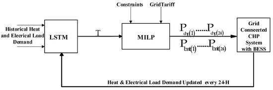
Figure 3.
LSTM-MILP flow model for real-time operation of the grid-connected CHP system (offline optimisation scheme).
One way of solving this problem is to dispatch only the CHP commands from the offline, ‘day-ahead’ optimisation. The BESS then balances the difference between generation and load demand in real time. While this scenario prevents reverse grid power, the system is likely to operate sub-optimally because the battery commands are not optimised
4.2. Online Implementation Using Receding Horizon
The RH method is derived from model predictive control (MPC), which addresses control issues by determining the current control action via online model-based optimisation [24]. It is a general-purpose control technique that continually solves a limited optimisation problem by utilising predicted power generation and load demand across a shifting time horizon to determine the control action. The RH control directly and intuitively handles limitations, such as limits on control variables, and provides accurately computed control actions that adhere to the constraints. The fundamental RH policy is simple and straightforward. At time t, we consider a period spanning T steps into the future (every half hour): as seen in Figure 4. This method can correct load prediction errors in future iterations for energy systems scheduling problems that depend heavily on load demand forecasts [25]. The RH is a proposed solution that is intended to minimise the impact of the prediction error and make it possible to implement the economic dispatch problem in real time. This problem is improved by the utilisation of real-time load data. An illustration of the implementation of the online EMS can be found in Figure 5.
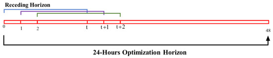
Figure 4.
Illustration of the RH control strategy.
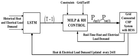
Figure 5.
LSTM-MILP-RH flow model for real-time operation of the grid-connected CHP system (online optimisation).
This paper uses MILP to model the system under consideration as an economic load dispatch optimisation problem over a period of 24 h consisting of 48-time steps (every half hour). For the future time horizon, the LSTM makes projections for both PV generation and load data. After that, the MILP and RH control strategy are applied to solve the economic dispatch problem [17]. Only the dispatch command for the real-time (first-time step) is applied to the CHP Units and BESS, and the process is repeated.
5. Results of Simulation
In this section, the specifics of the case study and the outcomes of the EMS deployment are discussed to demonstrate the technical specifications of the gas engines with six in-line cylinders that power the CHP units (GXC250-NG) [21]. You can see Table 2, Table 3, Table 4 and Table 5, the values in Table 3 are calculated from Table 2. Table 4 and Table 5 describe the components that make up the lithium-ion battery package and the cost of the daily time-of-use tariff for gas, respectively.
Table 2.
CHP Power and Efficiency @ 50 Hz.
Table 3.
The CHP Input-Output Curve (where (a, b, c) are the fuel cost coefficients).
Table 4.
Characteristics of the Lithium-Ion BESS Package.
Table 5.
Daily Time of Use (ToU) Electricity Tariff/Cost of Gas.
The economic dispatch and energy management system simulation was conducted in MATLAB on a computer with a 32 GB 64-bit operating system, dual-core i7, 2.70–2.90 GHz. The simulation’s average computing time was about 11.93 ± 2.012 s. The offline and online economic dispatch results with optimal cost comparison are presented below. The proposed economic dispatch simulation was performed in MATLAB language.
5.1. Load Prediction Using LSTM
In this section, deep learning based on LSTM is used to forecast future load demand and PV generation considering one year of historical data of the factory. LSTM networks are a sort of recurrent neural network (RNN) that have sequences of gates and are often referred to as modules rather than neurons. Each LSTM cell has a kind of long-term memory in the form of a cell state that is updated over time [26]. As an alternative to stochastic gradient descent (SGD), the LSTM model is trained using the Adam optimiser (adaptive movement optimisation), which uses a root-mean-squared error (RMSE) loss function. The maximum number of epochs has been set to 500, and the initial learn rate has been set at 0.005. The root-mean-squared error (RMSE) is a measure of predicting error that displays the gap between the expected and observed values [17,27]. The training and testing data must go through several pre-processing stages before being used to train or test a neural network. In this particular scenario, normalisation was utilised as a pre-processing strategy as a result of the fact that it lessens the impact of various scales on the acquired data, as well as to interpolate any data points that were missing and arranges the data (historical load demand) in chronological order. In the subsequent stage, the normalised data are fed into the LSTM network as input [17].
The RMSE is a suitable metric for evaluating the performance of the LSTM. The RMSE indicates the deviation between the predicted value and the actual measured value, and it is a measure of the forecasting error. In other words, the RMSE indicates how far off the predicted value is from the actual measured value. A lower RMSE Value indicates better performance, and the RMSE is computed with the following formula:
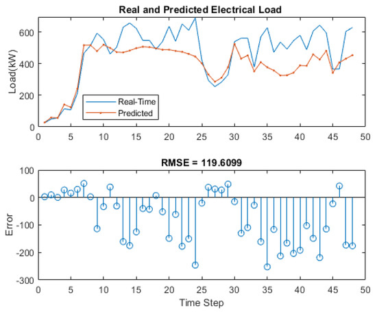
Figure 6.
Real and predicted electrical load with RMSE.
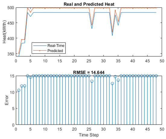
Figure 7.
Real and Predicted Heat Demand with RMSE.
5.2. EMS Implementation Results
Four Scenarios are considered in our simulations:
- Scenario 1 predicted data are the same as the real data; offline EMS provides dispatch commands to CHPs and the battery. This represents the ideal scenario, which is not achievable and does not exist in reality but provides a best-case benchmark for comparing the other scenarios.
- Scenario 2 predicted data are different from real data; offline EMS provides dispatch commands to CHPs and the battery.
- Scenario 3 predicted data are different from real data; offline EMS provides dispatch commands to CHPs only. The battery operates to balance generation and load in real-time.
- Scenario 4 predicted data are different from real data; online EMS provides dispatch commands to CHPs and batteries.
Figure 8 shows the electrical power, the heat generated from the CHP units, and the predicted load demand resulting from the offline optimisation in Scenario 1 using predicted data. The result of the first scenario, which is the ideal case, is shown in Figure 9, there is no power exported to or imported from the grid, and total generation equals load plus battery discharge power.
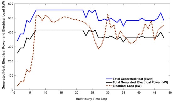
Figure 8.
Total output electrical power and heat generated from 2 × 250 kWe CHP units using predicted load demand data.
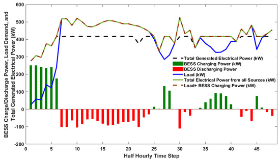
Figure 9.
Total electrical power generated, the ideal real-time load demand, and BESS charge/discharge command (scenario 1).
For the second scenario, the commands of the CHP units and the BESS from the offline optimisation are dispatched on the real-time data. The results are presented in Figure 10, while Figure 11 shows that power is exported to the grid whenever there is an excess generation, which violates the constraints as, in this case, we do not want to export power to the grid. For the third scenario, the offline EMS only provides the dispatch commands to the CHPs. At the same time, the BESS offsets the difference between the load demand and the dispatched CHP command in real time (BESS operated to balance the generation and the load). It can be seen from Figure 12 and Figure 13 that the total power generated equals the load demand plus battery charge power, and power is not exported into the grid. Since the CHP command for the three scenarios is based on offline optimisation, the total generated heat for all scenarios remains the same as in Figure 14, where the total generated heat is greater than or equal to the heat demand with excess heat stored in the heat buffer tank, respecting the constraint in Equation (2).
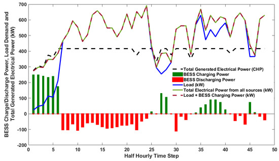
Figure 10.
Total electrical power generated, real-time load demand, and BESS charge/discharge command (Scenario 2).
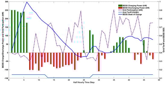
Figure 11.
Grid participation, BESS SoC, grid tariff, and BESS charge/discharge command (Scenario 2).
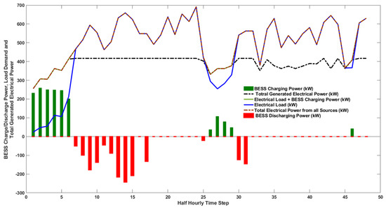
Figure 12.
Total electrical power generated, real-time load demand, and BESS charge/discharge command (Scenario 3).
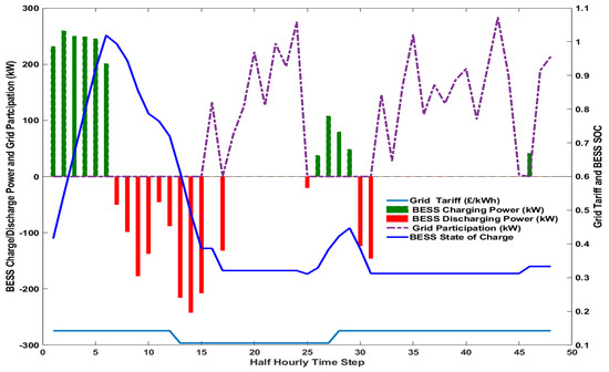
Figure 13.
Grid participation, BESS SoC, grid tariff, and BESS charge/discharge command (Scenario 3).
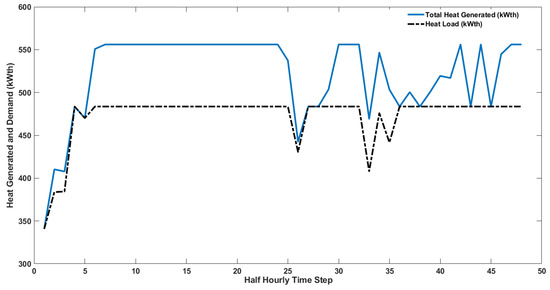
Figure 14.
Total heat generated by the CHP units and heat demand (offline optimisation).
For online optimisation (Scenario 4), the LSTM-MILP-RH approach has been used. The results are presented in Figure 15, Figure 16, Figure 17 and Figure 18. Figure 15 shows the total power generated by the two CHP units, the recoverable heat, and the difference between the power generated by the CHP units and the real-time load demand. Figure 16 shows that, with online optimisation, the total generated power from all sources can meet the load demand in real-time using the RH control strategy. The charge/discharge power of the BESS, the state of charge, and the power imported from the grid are shown in Figure 17. This confirms that the concept of real-time load following can easily be achieved using the proposed online optimisation method.
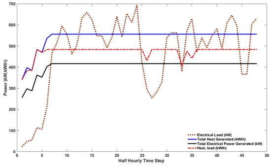
Figure 15.
Total power and heat generated from 2 × 250 kWe CHP units vs. real-time electrical load (online optimisation).
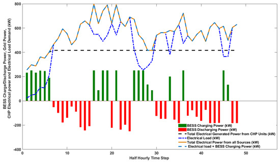
Figure 16.
Total electrical power generated, real-time load demand, and BESS charge/discharge command (scenario 4).
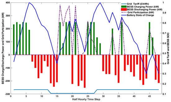
Figure 17.
Grid participation, BESS SoC, grid tariff, and BESS charge/discharge command (scenario 4).
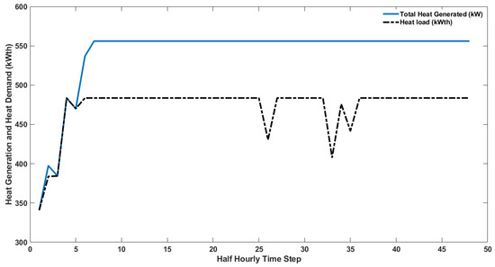
Figure 18.
Total heat generated by the CHP units and heat demand (online optimisation).
Figure 18 shows the total generated heat and heat demand, where the total generated heat is greater than or equal to the heat demand with excess generated heat stored in the buffer tank, respecting the constraint in Equation (2).
Table 6 shows the distinction between the grid-connected CHP system’s total operating cost when real-time offline and online optimisation is done and the factory’s total operating cost when supplied exclusively by the grid. The percentage savings provides insight into how online optimisation compares to offline optimisation (where just the CHP command is sent in real-time). The online optimisation strategy is superior when comparing grid utilisation, total operating cost, and percentage cost reductions for the investigated model. In terms of cost savings, Scenario 4’s online method is better than Scenario 3’s offline approach by 8.75%, and by 5.4% when comparing the two scenarios to the grid supply exclusively, and the difference is around 7.1% when comparing the two to Scenario 1 (ideal scenario).
Table 6.
Total daily operating cost and % saving for all scenarios.
6. Conclusions
This study analyses the financial viability of a hybrid grid-connected CHP system built to provide an industrial facility with the electricity and heat it needs to operate. Having established a minimum operating condition with varying load demand that sometimes falls below the minimum safe and economical operating condition for the CHP units, the emphasis is on keeping the CHP running continuously during production. This paper presents a real-time EMS based on RH that uses LSTM for load demand forecasting and MILP for operation optimisation. The proposed online EMS has been demonstrated to minimise operating costs compared to offline EMS via simulation. This is due to the online EMS’s enhanced capacity to rectify prediction errors using real-time data. In addition, the online EMS has been able to fulfil all the requirements, notably those regarding the control of power injection into the grid and the prevention of CHP units running below acceptable limits.
Author Contributions
Conceptualization, M.B.S., A.C.P. and M.A.; Methodology, M.B.S., S.D., A.C.P. and M.A.; Software, M.B.S.; Validation, M.B.S., S.D., A.C.P. and M.A.; Formal analysis, M.B.S., S.D., A.C.P. and M.A.; Investigation, M.B.S. and M.A.; Resources, M.B.S., S.D. and M.A.; Data curation, M.B.S. and M.A.; Writing—original draft, M.B.S. and M.A.; Writing—review & editing, S.D., A.C.P. and M.A.; Visualization, M.A.; Supervision, S.D., A.C.P. and M.A.; Project administration, M.A.; Funding acquisition, M.B.S. All authors have read and agreed to the published version of the manuscript.
Funding
Petroleum Technology Development Fund (PTDF Nigeria), University of Exeter and HiT Power Limited.
Data Availability Statement
The data set used in this research belongs to private company and can be made available on request.
Conflicts of Interest
To the best of our knowledge there are no conflict of interest.
Nomenclature
| Electrical power from both CHP units 1 and 2, respectively | |
| Power from the BESS to the load | |
| Power from the grid | |
| Electrical load demand | |
| Total electrical output power of the CHP units | |
| Useful heat recovery rate | |
| Recoverable heat from the CHP unit | |
| Segments of CHP units | |
| Power segments of CHP units | |
| The slope of each segment of the CHP Unit | |
| The minimum operating condition of the CHP unit | |
| Maximum power of each segment of the CHP unit | |
| CHP cost function | |
| The objective function | |
| Power from the grid to the electrical load demand | |
| Power from the grid for charging the BESS | |
| Heat load | |
| Power from the CHP units for charging the BESS | |
| Total BESS charging power | |
| Minimum state of charge of the BESS | |
| Maximum state of charge of the BESS | |
| BESS state of charge | |
| BESS nominal capacity (kWh) | |
| Charge and discharge efficiency of the BESS, respectively | |
| Time-step | |
| On and of state of the BESS charge and discharge, respectively. | |
| Time-of-use tariff of the grid | |
| CHP operating cost and start-up cost |
References
- Gielen, D.; Boshell, F.; Saygin, D.; Bazilian, M.D.; Wagner, N.; Gorini, R. The role of renewable energy in the global energy transformation. Energy Strategy Rev. 2019, 24, 38–50. [Google Scholar] [CrossRef]
- Sun, T.; Lu, J.; Li, Z.; Lubkeman, D.L.; Lu, N. Modeling Combined Heat and Power Systems for Microgrid Applications. IEEE Trans. Smart Grid 2017, 9, 4172–4180. [Google Scholar] [CrossRef]
- Landelle, A.; Tauveron, N.; Haberschill, P.; Revellin, R.; Colasson, S. Organic Rankine cycle design and performance comparison based on experimental database. Appl. Energy 2017, 204, 1172–1187. [Google Scholar] [CrossRef]
- Department for Business Energy and Industrial Strategy. Combined Heat and Power—Technologies. A Detailed Guide for CHP Developers—Part 2; Department for Business Energy and Industrial Strategy (BEIS): London, UK, 2021.
- Quoilin, S.; Broek, M.V.D.; Declaye, S.; Dewallef, P.; Lemort, V. Techno-economic survey of Organic Rankine Cycle (ORC) systems. Renew. Sustain. Energy Rev. 2013, 22, 168–186. [Google Scholar] [CrossRef]
- Fragaki, A.; Andersen, A.N.; Toke, D. Exploration of economical sizing of gas engine and thermal store for combined heat and power plants in the UK. Energy 2008, 33, 1659–1670. [Google Scholar] [CrossRef]
- Mustayen, A.G.M.B.; Wang, X.; Rasul, M.G.; Hamilton, J.; Negnevitsky, M. Theoretical Investigation of Combustion and Performance Analysis of Diesel Engine under Low Load Conditions. IOP Conf. Ser. Earth Environ. Sci. 2021, 838, 12013. [Google Scholar] [CrossRef]
- Tufte, E.D. Impacts of Low Load Operation of Modern Four-Stroke Diesel Engines in Generator Configuration. Master’s Thesis, Norwegian University of Science and Technology, Trondheim, Norway, 2018; p. 114. [Google Scholar]
- Heywood, J.B. Internal Combustion Engine Fundamentals, 2nd ed.; McGraw-Hill Education: New York, NY, USA, 2018; Available online: https://www.accessengineeringlibrary.com/content/book/9781260116106 (accessed on 15 April 2022).
- Chapa, M.G.; Galaz, J.V. An economic dispatch algorithm for cogeneration systems. In Proceedings of the IEEE Power Engineering Society General Meeting, Denver, CO, USA,, 6–10 June 2004. [Google Scholar] [CrossRef]
- Rotimi, A.; Bahadori-Jahromi, A.; Mylona, A.; Godfrey, P.; Cook, D. Optimum Size Selection of CHP Retrofitting in Existing UK Hotel Building. Sustainability 2018, 10, 2044. [Google Scholar] [CrossRef]
- Maleki, A.; Hafeznia, H.; Rosen, M.A.; Pourfayaz, F. Optimization of a grid-connected hybrid solar-wind-hydrogen CHP system for residential applications by efficient metaheuristic approaches. Appl. Therm. Eng. 2017, 123, 1263–1277. [Google Scholar] [CrossRef]
- Xie, D.; Chen, A.; Gu, C.; Tai, J. Time-Domain Modeling of Grid-Connected CHP for Its Interaction with the Power Grid. IEEE Trans. Power Syst. 2018, 33, 6430–6440. [Google Scholar] [CrossRef]
- Ma, L.; Liu, N.; Zhang, J.; Tushar, W.; Yuen, C. Energy Management for Joint Operation of CHP and PV Prosumers Inside a Grid-Connected Microgrid: A Game Theoretic Approach. IEEE Trans. Ind. Inform. 2016, 12, 1930–1942. [Google Scholar] [CrossRef]
- Nazari-Heris, M.; Abapour, S.; Mohammadi-Ivatloo, B. Optimal economic dispatch of FC-CHP based heat and power micro-grids. Appl. Therm. Eng. 2017, 114, 756–769. [Google Scholar] [CrossRef]
- Metz, D. Economic Evaluation of Energy Storage Systems, and their Impact on Electricity Markets in a Smart-grid Context. Ph.D. Thesis, Faculty of Engineering, University of Porto, Porto, Portugal, 2020; p. 240. [Google Scholar]
- Sigalo, M.B.; Pillai, A.C.; Das, S.; Abusara, M. An Energy Management System for the Control of Battery Storage in a Grid-Connected Microgrid Using Mixed Integer Linear Programming. Energies 2021, 14, 6212. [Google Scholar] [CrossRef]
- Ali, K.H.; Sigalo, M.; Das, S.; Anderlini, E.; Tahir, A.A.; Abusara, M. Reinforcement Learning for Energy-Storage Systems in Grid-Connected Microgrids: An Investigation of Online vs. Offline Implementation. Energies 2021, 14, 5688. [Google Scholar] [CrossRef]
- Sigalo, M.B. Energy Management of Grid-Connected Microgrids, Incorporating Battery Energy Storage and CHP Systems Using Mixed Integer Linear Programming Energy Management of Grid-Connected Microgrids, Incorporating Battery Energy Storage and CHP Systems Using Mixed. University of Exeter. 2023. Available online: http://hdl.handle.net/10871/132184 (accessed on 15 January 2023).
- Simons, G.; Barsun, S. Chapter 23: Combined Heat and Power Evaluation Protocol The Uniform Methods Project: Methods for Determining Energy Efficiency Savings for specific measures. Available online: https://www.nrel.gov/docs/fy17osti/68579.pdf (accessed on 24 October 2017).
- Standard Basic Module, Powerlink Power Systems Data Sheet for GXC250-NG Natural Gas CHP Unit. Available online: https://powerlinkworld.co.uk/wp-content/uploads/2021/01/1000352028_GXC250-NG_IN_B_S_E_P.pdf (accessed on 8 January 2022).
- Allen, J.; Wood, A.J.; Bruce, F.W.; Sheble, G.B. Power Generation, Operation, and Control, 3rd ed.; John Wiley & Son, Inc.: Hoboken, NJ, USA, 2014. [Google Scholar]
- Liu, C.; Zhang, H.; Shahidehpour, M.; Zhou, Q.; Ding, T. A Two-Layer Model for Microgrid Real-Time Scheduling Using Approximate Future Cost Function. IEEE Trans. Power Syst. 2021, 37, 1264–1273. [Google Scholar] [CrossRef]
- Milam, M.; Franz, R.; Hauser, J.; Murray, R. Receding horizon control of vectored thrust flight experiment. IEE Proc.—Control Theory Appl. 2005, 152, 340–348. [Google Scholar] [CrossRef]
- Hooshmand, A.; Mohammadpour, J.; Malk, H.; Danesh, H. Power System Dynamic Scheduling with High Integration of Renewable Sources. In Integrated Systems: Innovations and Applications; Springer: Berlin/Heidelberg, Germany, 2015; pp. 227–241. [Google Scholar] [CrossRef]
- Halpern-Wight, N.; Konstantinou, M.; Charalambides, A.G.; Reinders, A. Training and Testing of a Single-Layer LSTM Network for Near-Future Solar Forecasting. Appl. Sci. 2020, 10, 5873. [Google Scholar] [CrossRef]
- Kumar, A.G.; Sindhu, M.; Kumar, S.S. Deep Neural Network Based Hierarchical Control of Residential Microgrid Using LSTM. In Proceedings of the TENCON 2019—2019 IEEE Region 10 Conference (TENCON), Kochi, India, 17–20 October 2019; pp. 2129–2134. [Google Scholar] [CrossRef]
Disclaimer/Publisher’s Note: The statements, opinions and data contained in all publications are solely those of the individual author(s) and contributor(s) and not of MDPI and/or the editor(s). MDPI and/or the editor(s) disclaim responsibility for any injury to people or property resulting from any ideas, methods, instructions or products referred to in the content. |
© 2023 by the authors. Licensee MDPI, Basel, Switzerland. This article is an open access article distributed under the terms and conditions of the Creative Commons Attribution (CC BY) license (https://creativecommons.org/licenses/by/4.0/).