Article

Techno-Economic Green Optimization of Electrical Microgrid Using Swarm Metaheuristics

1
LDREI Laboratory, Department of Electrical Engineering, Higher School of Electrical Engineering and Energetic of Oran, Oran 31000, Algeria
2
Department of Computer Sciences, University of Sciences and the Technology of Oran (USTO-MB), Oran 31000, Algeria
3
UR InSyTE, Université de Technologie de Troyes, 12 Rue Marie Curie, CS 42060, 10004 Troyes, France
4
Department of Electrical Engineering, Engineering Faculty, University of Sidi Bel Abbes, Sidi Bel Abbès 22000, Algeria
*
Authors to whom correspondence should be addressed.
Energies 2023, 16(4), 1803; https://doi.org/10.3390/en16041803
Submission received: 21 December 2022 / Revised: 6 February 2023 / Accepted: 9 February 2023 / Published: 11 February 2023
(This article belongs to the Special Issue Distributed Generation Power Systems II)

Abstract

:
In electrical power engineering, elements such as reliability analysis, modeling, and optimization for complex systems are of the utmost importance. Although there exist myriad studies regarding reliability optimization with conventional methods, researchers are still seeking to find more efficient and accurate methods to address the issue of the redundancy allocation problem. To that effect, an ideal power energy management approach is put forward for the operation of a hybrid microgrid system with different kinds of productions. In the present study, we suggest three algorithms in order to optimize the series-parallel power energy system: the Firefly (FA), Bat (BA), and Interior Search (ISA) algorithms. Moreover, the reliability estimate of the system is solved with the Ushakov algorithm (UMGF). The components may completely fail, which decreases their performance rate. Furthermore, the optimization results are achieved using objective functions that include the total cost of the system, emission gases (NOX, SO2, and CO2) of the power production from fuel cells, diesel generators, and gas turbines, and take into consideration the dependability indices. Devices used in power subsystems are characterized based on their dependabilities, performances, capital costs, and maintenance costs. Reliability hinges on a functioning system, which naturally entails meeting customer demand; as a result, it is influenced by the accumulated batch curve. This method provides an idea with regards to the economic cost optimization of microgrid systems. Finally, we present the results of numeric simulations.

1. Introduction

In the redundancy allocation of homogeneous or heterogeneous subsystems, the goal of the problem is to choose the best components while also determining how reliable each subsystem is under the predetermined parameters and limitations of the system design, such as availability, cost, and space [1]. Continuous-state models support a continuum of states, and multi-state models support a finite number of states [2]. The state distribution in a multi-state system (MSS) is discrete, since there are a finite number of state realizations. The MSS has several uses in a variety of industries, including gas pipeline systems [3] and wind energy systems [4].
There are various publications concerning the multi-state system redundancy allocation problem (MSS RAP) in the literature. In order to solve the heterogeneous MSS RAP, Du and Li [5] investigated the memetic method with a local search. The component-level and subsystem-level repair activities in MSS RAP were recently examined by Attar et al. [6]. Xu et al. [7] considered the redundancy allocation problem (RAP) for MSS subject to probabilistic common-cause failure. Prioritizing economic system components without neglecting high efficiency reliability optimization was suggested in [8].
The literature contains a number of studies on sizing voltaic panels and battery energy storage systems (PV-BESS) to maximize a particular target or cost function. As an illustration, refs. [9,10] give a basic overview of several size approaches and strategies. These studies demonstrate the critical role that proper component sizing plays in addressing problems like aging, power quality, and environmental concerns that are frequently ignored. Using a mixed-integer nonlinear programming (MILP) method, the ideal PV and BESS sizing for the residential market is considered in [11,12], with the goal of reducing the overall annual power cost while taking the battery deterioration process into account. However, the analysis does not take the environmental factor into account. An online tool for sizing PV and BESS is provided in [13], for optimizing self-sufficiency and minimizing the environmental effect in residential settings by clustering several prosumers using a genetic algorithm (GA) [14].
According to Ayan et al. [15], applying the Artificial Bee Colony (ABC) algorithm to the scale optimization of renewable energy systems, leads to faster decision-making and better solutions. Demolli et al. [16] showed that because heuristic algorithms quickly identify the best solutions for hybrid renewable energy systems, they are more practical than deterministic methods. According to Kallio et al. [17], if a hybrid renewable energy system is functioning in a dynamic environment, brought on by climatic circumstances and/or energy demand, the dynamic exergy analysis is the best technique to assess it. Reddy Vaka et al. [18], used the particle swarm algorithm (PSO), to optimize the levelized cost of electricity (LCOE), reliability factor, and power supply reliability factor (PSRF), for battery energy storage systems (BESS) with a hybrid renewable energy system (HRES).
The power microgrid’s technical and financial limitations should be considered while meeting the demand load. According to several examples in the literature, an optimal component size according to load need is necessary for the effective planning and design of a hybrid microgrid (MG). By using different optimization methodologies, several studies have been conducted on the design, planning, and optimization of hybrid microgrids. However, the cost minimization is studied without examining either the reliability of the microgrid [19], or the probability of load loss [20]. In [21], the task comprises, reducing the cost of the energy storage installation, energy losses, maintenance, interruption, and system upgrading. The optimal energy storage placement in the distribution system is also analyzed. In [22], the authors tried to minimize the energy cost while reducing the emission rates of pollutants: nitrogen oxides (NOx), sulfur dioxide (SO2), and carbon dioxide (CO2). Distributed Energy Resources optimization is assessed by considering the utility rate, transportation constraints, and generator state. Another cost study, called annualized cost system (ACS), has been used in [23]. To reduce gas emissions, the economic scheduling model for electricity and natural gas systems is proposed in [24].
The principal purpose of this study is to model the green economic electrical microgrid design problem, that minimizes the net present cost (NPC) with the availability constraint, then to propose a combination between the Ushakov algorithm and a metaheuristic, which is the Interior Search Algorithm (ISA) [25]. The ecological objective concerns pollutant gases such as NOx, SO2, and CO2. The electrical microgrid uses a series–parallel structure with several subsystems, in which each of the subsystems uses a number of parallel components, as shown in Figure 1.
The most important contributions of this paper are summarized as follows:
A thorough technical and economic optimization technique for a hybrid microgrid system is described, in order to acquire an optimally priced design with respectable availability. As natural gas usage is taken into account in the objective function of the projected energy production, many approaches are investigated.
A formulation of the problem that combines economic and environmental factors is considered. While minimizing the cost in the objective function, a threshold of pollutant emission rate must not be exceeded in the objective function, in order to respect ecological principles and to reduce the negative impact on the environment and on human health.
The strategy of the optimum design is evaluated and the results confirm that the different types of available production sources successfully meet the load with a minimum cost.
The paper is divided into five sections. Section 2 describes the redundancy problem formulation and the microgrid components modeling. The optimization methodology is presented in Section 3. Section 4 presents a numerical example and computational results, to demonstrate the efficacy of the suggested methodology. The conclusions and future research are presented in Section 5.

2. Redundancy Allocation Problem for Microgrid

The Redundancy Allocation problem (RAP) is one of the most extensively researched dependability optimization issues. In terms of the mathematics, the system design turns into a combinatorial optimization for numerous systems made up of discrete component types that have varying costs, performances, and reliabilities. There may frequently be alternate component types with varying costs, performances, reliabilities, and other characteristics that can be used to provide the required system operations. The practical problem is to choose the best set of component types (decision variables) to fulfill the performance, reliability, space, and other limitations, while maximizing the reliability or minimizing the cost while reaching specified maximum (or minimum) values for other system aspects (constraints).

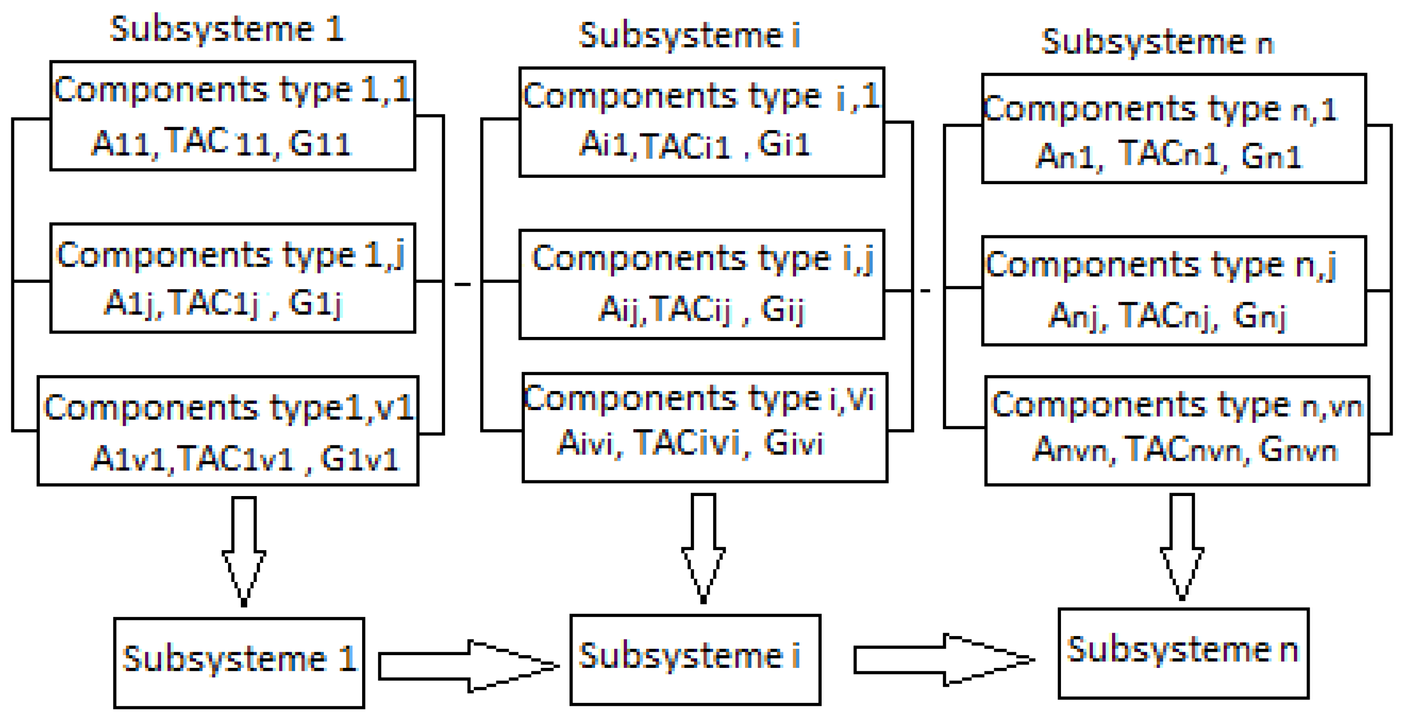
2.1. Problem Description

Consider a power microgrid network. A system with n series power subsystems (generators, substations, and lines) linked in series. Each subsystem i represents a component and has a number of device versions that are linked in parallel. Device j from subsystem i is defined by its availability (Aij) or reliability (Rij), total annual cost (TACij), and load capacity (Gij). The topology of subsystem i can be characterized by the number of parallel identical devices kij for 1 j Vi, where Vi is the number of available versions of type i as shown in Figure 2 [26].

2.2. Availability Estimation

To optimize the multi-state system redundancy, an effective evaluation process to predict the availability of each series-parallel combination is required. We consider a system having multi-state systems (MSS) that correlate to distinct levels of performance. The likelihood of satisfying the demand for repairable MSS is determined by Equation (1) [27], with G(h) is the system performance at hour h, and W is the demand.
R ( W ) = P { G ( h ) > W } = 1 P { G ( h ) W }
The present paper uses the universal moment generating function (UMGF) to evaluate the MSS availability [17], also known as the Ushakov method.
Ushakov introduced the UMGF ideas for assessing system dependability [27]. The reliability of multi-state series, parallel, and series-parallel systems is evaluated using UMGF. It is hard to assess the system reliability using traditional methods for a multi-state system since the system states expand considerably depending on the elements’ states. The UMGF of component j in subsystem i is characterized by Equation (2) [28]:
u ( z ) = j = 1 J P j z G j
The function u(z) may be used to determine the random variable G’s probabilistic properties. Specifically, if the stationary output performance of the MSS is the discrete random variable G, the availability A is provided by the probability (GW), which may be stated as follows:
p r o b a ( G W ) = ϕ ( u ( z ) z W )
when Φ is a distributive operator defined by Equations (4) and (5) [26]:
ϕ ( p j z σ w ) = { p , i f   σ w 0 , i f   σ w
ϕ ( j = 1 J p j z G j W ) = j = 1 J ϕ ( p j z G j W )
Furthermore, two fundamental operators are combined to measure availability. For a given set of elements, these operators define the polynomial u(z) [26].

2.2.1. Parallel Device

Using the dependability operator for parallel device ℑ operator, the universal moment generator function of a multi-state system connecting m redundant devices can be calculated, Equation (6):
u s ( z ) = ( u 1 ( z ) , u 2 ( z ) , ..... u m ( z ) )
In accord, Equation (7) shows how the operator is applied in a straightforward two-redundant device system:
( j = 1 J P j z G j W ) = i = 1 n j = 1 m P i Q i z a i + b j

2.2.2. Series Elements

The dependability operator for serial device δ, establishes its universal function [16] for a multi-state system with m elements in series, as shown in Equation (8):
u s ( z ) = δ ( u 1 ( z ) , u 2 ( z ) , ..... u m ( z ) )
Therefore, a simple application on two elements is defined by Equation (9):
δ ( u 1 ( z ) , u 2 ( z ) ) = i = 1 n j = 1 m P i Q j z min ( a i , b j )
Consequently, the universal moment function of a series-parallel system is attained by consecutively applying the two operators, where Pi is the performance probability of the ith device, and Qi is the performance probability of the jth subsystem.

2.3. Micro Grid Components Cost Modeling

In the reliability redundancy strategy, the generated energy from the micro turbine (MT), diesel generator (DG), fuel cell (FC), and the performance of the substation and line power are determined. The model of each component is used to determine their costs, availabilities, reliabilities, and their performances to satisfy consumers [29].
The low-voltage system under study, or MG, operates separately from the electrical grid (off-grid). Therefore, it is important to regulate the frequency, voltage, and load demand. The MG has a fuel cell, a diesel generator, a micro turbine, and other loads. Commercial, industrial, and residential loads were divided up. The examined microgrid is shown in Figure 1. The next subsections provide an explanation of the MG’s components [30].

2.3.1. Micro Turbine Cost

One of the generation resources is the micro turbine (MT), which operates in both grid-connected and off-grid modes. Micro turbines (MTs) have advantages over other diesel generators (DGs), including more revenue, less inertia, and quicker response times than normal gas turbines. MTs may run on a range of fuels, including propane, natural gas, diesel, hydrogen, and diesel [31]. From 5 kW to 100 kW is the range of the rated power turbine (PMT) of MTs [32]. The fuel cost and fixed cost (installation) that make up the cost function of the micro turbine (MT) are always present, and may be expressed by Equation (10), where b1 and b0 a are cost coefficients of the micro turbine [30].
f M T ( h ) = ( b 0 P M T ( h ) + b 1 )  

2.3.2. Diesel Generator Cost

A diesel engine and synchronous generator are connected on the same axis to create a diesel generator. In addition to providing electricity, diesel generators may serve as backup and emergency power sources for important facilities like hospitals, airports, etc. [33]. Diesel generators in off-grid MGs can help with frequency management, in addition to producing electricity. Equation (11) can be used at any moment to express the energy produced by diesel generators with nominal power PDG, where a2, a1, and a0 are the cost coefficients of the diesel generator [30,34]:
f D G ( h ) = ( a 0 P D G 2 ( h ) + a 1 P D G ( h ) + a 2 )

2.3.3. Fuel Cell Cost

A device called a fuel cell (FC) converts the chemical energy of PFC fuel directly into electrical energy [35]. FCs are divided into two classes based on the type of electrolyte they employ and their operating temperature: low temperature PEMFCs (proton exchange membrane fuel cells) and SOFCs (solid-oxide fuel cells) [36]. Equation (12) may be used to calculate the fixed cost and fuel cost for FCs (12), where c1 and c0 are the cost coefficients of the fuel cell [30]:
f F C ( h ) = ( c 0 P F C ( h ) + c 1 )

2.4. Environmental and Economic Objective Function

A system’s Total Annual Cost (TAC) is the sum of all of its expenses throughout the course of its existence. The cost of installing, replacing, running, and maintaining each component that is part of the MG system, the cost of fuel utilized, and the fine for emissions are all calculated using the Total Annual Cost (TAC) approach. The goal of this article is to reduce pollution, increase system dependability, and decrease overall yearly cost [19]. Equation (13) may be used to calculate the minimized cost:
Min {TAC = (Fuel & Capital cost + Operation & Maintenance cost + Emission cost)}
TAC = ( F M C ( t ) + O & M M C ( t ) + P L M C ( t ) )
where FMC(t) represents the fuel and capital costs, as shown in Equation (14). The O&MMC(t) represents the operation and maintenance costs, as shown in Equation (17), and the PLMC(t) is the emission (pollution) gas, as shown in Equation (19). Thus the mathematical formulation of the objective function can be written as follows [30]:

2.4.1. Fuel & Capital Cost

F M C ( t ) = ( f 1 j ( t ) × k 1 j ) + ( C c a p / s u b × k s u b , j ) + ( C c a p / l i n e × k l i n e , j )
As the fuel cost in the first subsystem depends on MT, DG, and FC:
F M C ( t ) = [ ( f M T ( t ) × k 1 M T ) + ( f D G ( t ) × k 1 D G ) + ( f F C ( t ) × k 1 F C ) + ( C c a p / s u b × k s u b , j ) + ( C c a p / l i n e × k l i n e , j ) ]
By detailing more the previous equations:
F M C ( t ) = [ ( b 0 P M T ( t ) + b 1 ) × k 1 M T ] + [ ( a 0 P D G 2 ( t ) + a 1 P D G ( t ) + a 2 ) × k 1 D G ] + [ ( C 0 P F C ( t ) + C 1 ) × k 1 F C ] + [ C c a p s u b 35 × k s u b 35 ] + [ C c a p l i n e 8.5 × k l i n e 8.5 ] + [ C c a p l i n e 36 × k l i n e 36 ] + [ C c a p / s u b 10 × k s u b 10 ]
where PMT, PDG, PFC, Ccap/sub, and Ccap/line are the generated powers of the micro-turbine, diesel generator, fuel cell, capital cost of substation and electrical line, respectively.

2.4.2. Operation & Maintenance Cost

O & M M C ( t ) = ( O M 1 j ( t ) × P 1 j ( t ) × k 1 j × t ) ( O & M s u b × k s u b , j ) + ( O & M l i n e × k l i n e , j )
As the operation and maintenance costs in the first subsystem depend on MT, DG, and FC, each one has its own power P and expanding substations and lines, the detailed formula obtained is:
O & M M C ( t ) = [ ( t × ( O M M T ( t ) × P M T ( t ) × k 1 M T ) + ( t × ( O M D G ( t ) × P D G ( t ) × k 1 D G ) ] + ( t × ( O M F C ( t ) × P F C ( t ) × k 1 F C ) + ( O M s u b 35 ( t ) × k s u b 35 ) + ( O M s u b 36 ( t ) × k s u b 36 ) + ( O M l i n e 10 ( t ) × k l i n e 10 ) + ( O M l i n e 8.5 ( t ) × k l i n e 8.5 )

2.4.3. Pollution Emission

P L M C ( t ) = j 1 P 1 j ( t ) × E C 1 j ( t ) × k 1 j
The power and the emission depend on the kind of element, MT, DG, and FC [30]:
P L M C ( t ) = ( P M T ( t ) × E C M T ( t ) × k 1 M T ) + ( P D G ( t ) × E C D G ( t ) × k 1 D G ) + ( P F C ( t ) × E C F C ( t ) × k 1 F C )
when expanding emission according to the three pollutants, NOx, SO2, and CO2, and using their emission cost β, the formula can be as given below (Equation (21)), where j in the first subsystem can be MT, DG, or FC, and k1j is the optimal number of redundant elements [30]:
P L M C h = t × j = M T , D G , F C 1 P 1 j ( t ) × [ ( β 1 j , N O x ) + ( β 1 j , S O 2 ) + ( β 1 j , C O 2 ) ] × k 1 j

2.4.4. Net Present Cost

The Net Present Cost (NPC) of MG is calculated in [36,37] with Equation (22), where TAC, is the Total Annual Cost and CRF the capital recovery facto:
N P C Y = T A C C R F Y

2.4.5. Capital Recovery Factor

The capital recovery factor (CRF) [19] is the ratio of an annuity to the present value of receiving that annuity for a project lifetime Y (in this study, 20 years). It is calculated by Equation (23) [38]:
C R F Y = S ( 1 + S ) Y ( 1 + S ) Y 1
The real S, interest rate, which is a function of the annual inflation rate f (here, 6%) and nominal interest rate d (here, 5%), is calculated by Equation (24) [38]:
S = d f 1 + f

2.4.6. Energy Production Cost

The Energy production cost is calculated by Equation (25), where EDtot is the sum of the total load demand during 8760 h [38].
E P C Y = N P C Y E D t o t

2.5. Constraints

The total power generated by DG, MT, and FC should satisfy the total MG demand. Therefore, the optimization problem constraints in this paper include reliability with Equation (26), pollution by Equation (27), performance by Equation (28) and output power of each type of power generation units in subsystem 1, Equation (29). These constraints are expressed as follows [19]:
i = 1 n j = 1 m P i Q j Z min ( a i , b j ) R 0
{ t × j = M T , D G , F C 1 P 1 j ( t ) × [ ( β 1 j , N O x ) + ( β 1 j , S O 2 ) + ( β 1 j , C O 2 ) ] × k 1 j } P L 0
G min ( a i , b j ) G 0
In this paper, MT, DG, and FC, produce power between some minimal and maximal limits. This is formulated as:
{ P M T m i n P M T ( t ) P M T m a x P D G m i n P D G ( t ) P D G m a x P F C m i n P F C ( t ) P F C m a x

3. Optimization Methodology

In this paper, the proposed metaheuristic ISA [39] for solving the bi-objective MSS RAP problem is presented in Section 3.1. Two other algorithms, the firefly algorithm (FA) [40] and bat algorithm (BA) [41], are described in Section 3.1.

3.1. Interior Search Algorithm (ISA)

In 2014, Gandomi introduced the Interior Search Algorithm (ISA), a novel global optimization algorithm that drew its inspiration from Persian art’s interior design methods [39,42]. It is a brand-new approach to optimization that is reliable, adaptable, and able to handle search areas of any size. It converges more quickly than most well-known algorithms. It has been applied in a variety of real-world contexts, such as fractional order and Butterworth filter optimization [43]. Karthik et al. studied the use ISA for economic load dispatch in a microgrid [44]. Bhesdadiya et al. solved the training multilayer perceptrons using ISA [45].
The metaheuristic functions in two distinct ways. To begin with, during the composition phase, solutions are shifted toward the ideal solution. Second, by positioning a mirror between the existing solutions and the ideal solution, inspection of the mirror is employed to produce an optimal perspective [46].
  • Find the positions of items between lower and higher boundaries (LB and UB) at random, then calculate their fitness values.
  • Find the global best element xjgb, or the fittest element (for a minimization issue, this element has the smallest objective function), on the jth iteration.
  • Use a threshold value, alpha, and random variables, r1, to randomly split the other items into two groups: the composition group and the mirror group (ranging from 0 to 1 for each element). In the mirror group, elements with r1 are placed; otherwise, they are placed in the composition group. In theory, alpha can have a value between 0 and 1.
  • However, as it is the single parameter in the algorithm, it should be carefully adjusted to strike a balance between intensity and diversification. It is preferable to use the random walk method for a local search around the global best to significantly alter its position. It may be stated as follows:
    x g b j = x g b j 1 + r n × λ
    where rn is a vector of randomly generated numbers with a normal distribution, and λ is a scale factor equal to:
    λ = 0.01 × ( U B L B )
  • For the composition group, each element’s makeup is altered at random. The boundary conditions (upper bounds and lower bounds) are modified for this collection of elements, which can be stated as follows:
    x i j = L B j + ( U B j L B j ) × r 2
    where xij is the ith element in the jth iteration; r2 is a random number between 0 and 1; LBj and UBj are the lower and upper bounds of the items in the jth iteration, respectively, and they are the minimum and maximum values of all elements in the (j − 1)th iteration.
  • A mirror is randomly put between each element and the element with the best fit for the mirror group (global best). The jth iteration’s position of a mirror for the ith element is defined as follows:
    x m , i j = r 3 x i j 1 + ( 1 r 3 ) x g b j
    where r3 varies at random from 0 to 1. The placement of the mirror determines the image’s or element’s virtual location, which can be expressed as follows:
    x i j = 2 x m , i j x i j 1
  • The fitness values of the virtual and new positions of the elements are computed. If a location’s fitness improves, it is updated. This can be stated in terms of a minimization equation as:
    { x i j         f ( x i j ) < f ( x i j 1 ) x i j 1                                             E l s e
  • Restart at step 2 if any of the stop criteria (such as the maximum number of repetitions) are not met.
The Algorithm 1 is described below [39].
Algorithm 1: The Interior Search Algorithm (ISA).
1 Initialization
2 while any stop criteria is not satisfied find the x g b j
3 for i = 1 to n
4 if xgb
5 x g b j = x g b j 1 + r n × λ
6 else if r i a
7 x i j = L B j + ( U B j L B j ) × r 2
8 else
9 x m , i j = r 3 x i j 1 + ( 1 r 3 ) x g b j
10 x i j = 2 x m , i j x i j 1
11 end if
12 check the boundaries except for decomposition elements
13 end for
14 for i = 1 to n
15 Evaluate f ( x i j )
16 x i j = { x i j f ( x i j ) f ( x i j 1 ) x i j 1 E l s e
17 end
The basic interior search algorithm was developed to optimize continuous optimization problems, whereas the retained redundancy problem is a combinatorial problem. It is a quadratic knapsack like problem. In this work, the standard interior search algorithm is discretized following some principles:
The solution is coded as an integer number representing the occurrence of a version in its subsystem.
First, all solutions are generated using a constructive heuristic between a lower bound and upper bound, where the lower bound can be 0 (LB = 0), which means that we can ignore a version while selecting elements. The upper bound should respect the number of all heterogeneous elements that can be taken in a subsystem, UB1 = 8 as an example, and the number of homogeneous elements with the same version, UB2 = 7 as an example.
After the decors movement in the algorithm, and before reliability estimation, real solutions are corrected using a uniform boundary constraint scheme.
The algorithm was also combined with the Ushakov technique to estimate efficiently the reliabilities in each step.

3.2. Bat Algorithm (BA)

Yang [41], proposed the bat algorithm, which is a swarm metaheuristic. It is based on the echolocation of bats, which produce sound waves with certain frequencies and pulse rates [26]. The bat algorithm has been demonstrated to be applicable in a variety of combinatory and continuous optimization fields, such as the optimal coordination of protection systems based on directional overcurrent relays [47], the dynamic membrane structure for optimization problems [48], finding all Pareto solutions of the series-parallel redundancy allocation problem with mixed components [49], Multiple Strategies Coupling for Numerical Optimization [50], and environmental economic power dispatch problems [51].
The frequencies vector f contains integers or real numbers based on the minimal and maximal frequency values, which can be specified by Equation (36) [41]
f i = f m i n + ( f m a x f m i n ) r a n d ( ) ,                             r a n d [ 0.1 ]
Positive double numbers represent the velocities V of bats. Velocities suggest bat flight, which should be altered at some point. A bat communicates with other bats by employing the best global solution, gbest, as defined by Equation (37) [41]:
V i = V i + ( X i g b e s t ) f i
The position can be updated using either the velocity specified by Equation (38) or the best overall solution defined by Equation (39) [41]:
X i = b e s t   i + V i
X i = g b e s t + r a n d o m ( 1 , 1 ) . A m o y
Or randomly by Equation (40) [41]:
X i = g i + r a n d o m ( 1 , 1 ) . A m o y
A is the average sound level of bats, which can be given by Equation (41) [41]:
A i = α A i , α [ 0 , 1 ]
ri are the pulsation rate values, as defined by Equation (42) [41]:
r i = r i 0 ( 1 e ( γ t ) )
with ri0 as a starting pulsation rate, γ > 0, and t as the rank of the current algorithm generation.

3.3. Firefly Algorithm (FA)

Yang [40], proposed the Firefly algorithm, which was inspired by the flashing behavior of fireflies. The primary functions of firefly flashing lights are to communicate (such as attracting mating partners) and to attract potential prey. Inspired by this, the firefly method was created by idealizing some of the flashing properties of fireflies and modeling each individual optimization problem solution as a firefly in a population [52]. Fireflies are small winged beetles that produce cold light flashes to attract mates. They are members of the Lampyridae family. They are thought to have a capacitor-like mechanism that progressively charges until a particular threshold is reached, at which point they release energy in the form of light, and the cycle begins again [52,53]. The firefly algorithm has been used in several areas such as, symbolic regression problems [54], realization of the firefly bioluminescence cycle in vitro and in cells [55], and photovoltaic MPPT under partial shading conditions [56].
The following are three major idealized rules [40]:
Because all fireflies in the population are unisex, any individual firefly will be drawn to other fireflies.
In any pair of fireflies, the less luminous one will gravitate toward the brighter one. The attraction of a firefly is proportionately tied to its brightness, which diminishes as the distance between two fireflies increases.
The brightness of a firefly is proportionally related to the value of the objective function, which is analogous to the fitness in a genetic algorithm.
There are four critical issues in the firefly algorithm:

3.3.1. Light Intensity

The brightness I of a firefly at a specific location x can be chosen as I(x) ∝ 1/f(x) in the simplest case for a minimum optimization problem [40].

3.3.2. Attractiveness

The main form of the attractiveness function in the firefly algorithm can be any monotonically decreasing function, such as the following generalized form given by Equation (43) [40], where r is the distance between two fireflies, β 0 * represents the attractiveness at r = 0, and γ is a constant light absorption coefficient:
β i , j = β 0 * e γ r i , j m

3.3.3. Distance

The Cartesian distance between any two fireflies i and j at xi and xj can be calculated by Equation (44) [40], where xi,k is the kth component of the ith firefly.
r i , j = k = 1 d ( x i , k x j , ) 2

3.3.4. Movement

The movement of a firefly i attracted to another, more attractive (brighter), firefly j, is determined by Equation (45), where the first and second terms are due to attraction and the third term is randomization, where the randomization parameter “rand”, is a random number generator uniformly distributed in the range [0, 1] [40].
x i = ( 1 β i , j ) x i + β i , j x j + α ( r a n d 1 2 )

4. Computational Experiments and Results

4.1. Case Study

In this section a numerical example is presented to illustrate the considered problem and the proposed methodology. The MGRAP were solved by using the ISA, FA, and BA algorithms presented in the previous section, implemented in C++, on a PC with an Intel Core™ i5-7th CPU 2.7 GHz processor and 12 GB RAM, under the Windows 10 operating system. The simulation results depend greatly on the ISA, BA, and FA algorithms’ parameters’ values. Table 1 presents the parameters used in the different algorithms.
The five subsystems that make up the MG are linked in series, with a homogenous design for electrical lines and substations, each subsystem was linked in parallel. For each subsystem, there are 10 different component types accessible. A subsystem may be allocated a minimum of one component and a maximum of 10 components. Component performances, dependabilities, and various expenses make up the input data (fuel, capital and O&MC).
The proposed optimization method is applied to a microgrid (Figure 1). The load demand curve is shown in Table 2. The data of the curve is obtained from [26]. Tm is a time period in hours, with m number of demand period intervals, and W is the power produced during this period.
The cost coefficients and power limits of FC, DG, and MT are introduced in Table 3, Table 4 and Table 5, respectively [30]. The capital cost, and operational and maintenance costs of units, shown in Table 6, are obtained from [30,57]. The emission factors of units are given in Table 7 [30].

4.2. Results

The findings of microgrid system size are presented and analyzed in this section. Each decision variable’s lower and upper bounds (NMT, NDG, NFC, NSub, and NL) were set to 1 and 10, respectively. The findings of the algorithms are summarized in Table 8 and Table 9. This research considers two scenarios.

4.2.1. Scenario: Min Cost & Max Reliability

In this case, the objective is to minimize the total annual cost and maximize the reliability under pollution and performance constraints. Table 8 shows the results of the optimal values of the MC system. It can be seen that MT production is the most cost-effective technique, and reliable for meeting load demand using the ISA method. The TAC for MG systems achieved by ISA is EUR 1.61407 M, with a pollution rate of 741.33 kg, while the TAC for the MT/DG production systems produced by BA is EUR 1.6365 M, with a pollution rate of 4688.59 kg. The three algorithms produce a maximum dependability of 97%. Table 7 shows that the ISA and FA produce more economical results than the BA algorithm for the MT/DG/FC systems, except for BA which was marginally less good than ISA and FA for a reliability constraint of 99%, with a pollution rate of 555.99 kg. For a reliability of 97%, the results show that ISA gives the best result compared to BA and FA, whether it is for the TAC or the emission rate.
For example, ISA’s optimal sizings for a reliability constraint equal to 97% is, NMT = 4, NDG = 0, NFC = 0, NSub35 = 2, NL36 = 4, NSub10 = 4, NL8,5 = 3, and for BA is, NMT = 4, NDG = 4, NFC = 0, NSub35 = 2, NL36 = 4, NSub10 = 3, NL8,5 = 5.

4.2.2. Scenario: Min Cost & Min Emission

In this scenario, the objectives are to minimize the total annual cost and to minimize the emission, under reliability and performance constraints. Table 9 shows the results of the optimal values for the MC system. It can be observed that the production by MT is the most economical and environmental system to supply the load demand by the ISA and FA based methods, with a reliability constraint of 99%. The Total Annual Cost (TAC) of the MG system obtained by ISA is EUR 1.8952 M, with a 555.997 kg rate of pollution, and EUR 1.9093 M, with a 555.997 kg rate of pollution for FA, while the TAC obtained by BA is EUR 2.2392 M, with a 741.3292 kg rate of pollution. We note that the BA algorithm gives a maximum reliability of 99.8%. Table 9 shows that, for a reliability constraint of 97%, ISA and FA produce more economical and environmental results than the BA algorithm, which was better than ISA and FA, with a reliability equal to 99.5%.
The optimal sizings obtained by ISA, for example for a reliability constraint equal to 99% is, NMT = 3, NDG = 0, NFC = 0, NSub35 = 3, NL36 = 3, NSub10 = 3, NL8, 5 = 3, and for BA is, NMT = 4, NDG = 0, NFC = 0, NSub35 = 3, NL36 = 5, NSub10 = 6, NL8, 5 = 6.

5. Conclusions

In industry, the series-parallel system redundancy allocation problem (RAP) is not easy to solve in real cases, especially for large-scale situations. Therefore, it is suggested to use metaheuristic methods to solve such a difficult and complex problem. In this paper, a human behavior inspired metaheuristic algorithm, called the interior search algorithm (ISA), is used. The concept of the ISA has been inspired by shutter decoration. The aim of this study is to determine the optimal size of the microgrid components, taking into account different parameters, such as operating costs, reliability, and the amount of pollutant gas emission. For this purpose, a cost-based analytical formulation is proposed. The proposed mathematical model applies to a grid-disconnected MG using, MT, DG, or FC as generation units. In the objective function, we considered simultaneously the different costs, such as fuel cost, operation and maintenance of the power generation units, operation, and maintenance and capital costs of the substations and power lines. At the same time, various constraints had to be taken into account, which is one of the advantages of this paper.
The results showed that there was a significant reduction in greenhouse gas emissions when micro turbines were used in the generation system. Taking into account the total costs, the quality of reliability, and the reduction of greenhouse gas emissions as objective functions, it can be concluded that the ISA algorithm has shown a great ability to find optimal solutions.
In the future, the authors are working on the extension of the series-parallel system in the case of heterogeneous reliability allocation with the integration of renewable energy. However, other structures, such as microgrids connected to the transmission grid, can be considered for future studies. Furthermore, the interior search algorithm can be improved by hybridizing it with the firefly algorithm (FA) or bat (BA) algorithm.

Author Contributions

Conceptualization was done by K.G. and A.Z., methodology by K.G. and L.D., software by L.D., validation by E.C., research by K.G., L.D. and A.Z., first draft writing by K.G. and L.D., second draft writing by E.C. and A.Z., and project management by K.G. and L.D. The manuscript’s published form was approved by all authors once they had read it. All authors have read and agreed to the published version of the manuscript.

Funding

This research received no external funding.

Data Availability Statement

Not applicable.

Acknowledgments

The authors thank the support of the DGRSDT.dz and the ATRST, for the creation of the new laboratory LDREI.

Conflicts of Interest

The authors declare no conflict of interest.

Abbreviations

ISAInterior search algorithm
MSSMulti states system
UMGFUniversal moment generating function
FAFirefly algorithm
BABat algorithm
NPCNet present cost
TACTotal annual cost
MGMicro grid
CRFCapital recovery factor
EPCEnergy production cost
MTMicro turbine
DGDiesel generator
FCFuel cell
NOxNitrogen Oxides
SOxSulfur dioxide
CO2Carbone dioxide
RAPRedundancy Allocation problem
PSOParticle swarm optimization
LCOELevelized cost of electricity
PSRFPower supply reliability factor
BESSBattery energy storage system
HRESHybrid renewable energy system
PVPanels voltaic
MILPMixed-integer nonlinear programming
GAGenetic algorithm
ABCArtificial bee colony
PEMFCsproton exchange membrane fuel cells
SOFCssolid-oxide fuel cells
O&MMC(t)operation and maintenance cost
Ccap/subcapital cost of substation
Ccap/linecapital cost of electrical line
PLMC(t)emission (pollution) gas
Nomenclature
SymbolMeaning
t/hOperating time (hours)
mNumber of demand period interval
FMChCost function of micro turbine at time h
NNumber of components in each subsystem
SRate interest of micro grid finance installations
YLifetime of the project (years)
fAnnual inflation rate
EDtotThe sum of the load demand during 8760 h
PMThMicro turbine power generated at time h [kW]
PDGhDiesel generator power generated at time h [kW]
PFChFuel cell power generated at time h [kW]
bo, b1Cost function coefficients of micro turbine
ao, a1, a2Cost function coefficients of diesel generator
c0, c1Cost function coefficients of Fuel cell
βiEmission factor of pollutant j by unit i including micro turbine DG and, FC.
GiPerformance of power component i
G0Minimum performance of power component i
RiReliability of power component i (%).
i,jRespectively indices of series, versions and demand period interval
nNumber of series i
ViNumber of Available electrical components technologies of type i
kijNumber of occurrences of component j in series i
RijReliability of power component j of type i (%)
R0Minimum reliability required (%)
PLpollution (emission) (kg)
PL0Maximum tolerated polluant emission (kg)
MNumber of demand period interval.
KmaxMaximum number that can be taken from each component j
PiPerformance probability of ith device
QiPerformance probability of jth subsystems
WDemand levels
TmTime period in hours
Reliability Operator for parallel device
δReliability Operator for series device.
Ccap/subCapital cost of a substation
Ksub,jNumber of a substation
Ccap/lineCapital cost of a line
Kline,jNumber of a line
PFCmaxMaximum power of a fuel cell
PFCminMaximum power of a micro-turbine
PDGminMaximum power of a diesel generator
xjgb,Global best
rnVector of normally distributed random numbers
λScale factor
rsRandom value between 0 and 1

References

  1. Chaaban, W.; Schwarz, M.; Börcsök, J. Cost optimization and redundancy allocation of availability constrained heterogeneous series-parallel systems using genetic computing. In Proceedings of the 1st International Conference on Mathematical Methods & Computational Techniques in Science & Engineering (MMCTSE 2014), Athens, Greece, 30 October 30–1 November 2014. [Google Scholar]
  2. Li, Z.; Kapur, K.C. Continuous-state reliability measures based on fuzzy sets. IEEE Trans. 2012, 44, 1033–1044. [Google Scholar] [CrossRef]
  3. Bao, M.; Ding, Y.; Yin, X.; Shao, C.; Ye, C. Definitions and reliability evaluation of multi-state systems considering state transition process and its application for gas systems. Reliab. Eng. Syst. Saf. 2021, 207, 107387. [Google Scholar] [CrossRef]
  4. Eryilmaz, S. Reliability analysis of multi-state system with three-state components and its application to wind energy. Reliab. Eng. Syst. Saf. 2018, 172, 58–63. [Google Scholar] [CrossRef]
  5. Du, M.; Li, Y. An investigation of new local search strategies in memetic algorithm for redundancy allocation in multi-state series-parallel systems. Reliab. Eng. Syst. Saf. 2020, 195, 106703. [Google Scholar] [CrossRef]
  6. Attar, A.; Raissi, S.; Damghani, K.K. A simulation-based optimization approach for free distributed repairable multi-state availability-redundancy allocation problems. Reliab. Eng. Syst. Saf. 2017, 157, 177–191. [Google Scholar] [CrossRef]
  7. Xu, Y.; Pi, D.; Yang, S.; Chen, Y. A novel discrete bat algorithm for heterogeneous redundancy allocation of multi-state systems subject to probabilistic commoncause failure. Reliab. Eng. Syst. Saf. 2021, 208, 107338. [Google Scholar] [CrossRef]
  8. Liu, M.; Wang, D.; Zhao, J.; Si, S. Importance measure construction and solving algorithm oriented to the cost-constrained reliability optimization model. Reliab. Eng. Syst. Saf. 2022, 222, 108406. [Google Scholar] [CrossRef]
  9. Hannan, M.A.; Wali, S.B.; Ker, P.J.; Abd Rahman, M.S.; Mansor, M.; Ramachandaramurthy, V.K.; Muttaqi, K.M.; Mahlia, T.M.I.; Dong, Z.Y. Battery energy-storage system: A review of technologies, optimization objectives, constraints, approaches, and outstanding issues. J. Energy Storage 2021, 42, 103023. [Google Scholar] [CrossRef]
  10. Khezri, R.; Mahmoudi, A.; Aki, H. Optimal planning of solar photovoltaic and battery storage systems for grid-connected residential sector: Review, challenges and new perspectives. Renew. Sustain. Energ. Rev. 2022, 153, 111763. [Google Scholar] [CrossRef]
  11. Mulleriyawage, U.G.K.; Shen, W.X. Optimally sizing of battery energy storage capacity by operational optimization of residential PV-Battery systems: An Australian household case study. Renew. Energy 2020, 160, 852–864. [Google Scholar] [CrossRef]
  12. Hesse, H.C.; Martins, R.; Musilek, P.; Naumann, M.; Truong, C.N.; Jossen, A. Economic Optimization of Component Sizing for Residential Battery Storage Systems. Energies 2017, 10, 835. [Google Scholar] [CrossRef]
  13. Korjani, S.; Casu, F.; Damiano, A.; Pilloni, V.; Serpi, A. An online energy management tool for sizing integrated PV-BESS systems for residential prosumers. Appl. Energy 2022, 313, 118765. [Google Scholar] [CrossRef]
  14. Blasuttigh, N.; Negri, S.; Pavan, A.M.; Tironi, E. Optimal Sizing and Environ-Economic Analysis of PV-BESS Systems for Jointly Acting Renewable Self-Consumers. Energies 2023, 16, 1244. [Google Scholar] [CrossRef]
  15. Ayan, S.; Toylan, H. Size optimization of a stand-alone hybrid photovoltaic/wind/battery renewable energy system using a heuristic optimization algorithm. Energy. Res. 2022, 46, 14908–14925. [Google Scholar] [CrossRef]
  16. Demolli, H.; Dokuz, A.S.; Ecemis, A.; Gokcek, M. Location-based optimal sizing of hybrid renewable energy systems using deterministic and heuristic algorithms. Energy Res. 2021, 45, 16155–16175. [Google Scholar] [CrossRef]
  17. Kallio, S.; Siroux, M. Exergy and Exergy-Economic Approach to Evaluate Hybrid Renewable Energy Systems in Buildings. Energies 2023, 16, 1029. [Google Scholar] [CrossRef]
  18. Vaka, S.S.K.R.; Matam, S.K. Optimal sizing of hybrid renewable energy systems for reliability enhancement and cost minimization using multiobjective technique in microgrids. Energy Search 2022, e419. [Google Scholar] [CrossRef]
  19. Tooryan, F.; HassanzadehFard, H.; Collins, E.R.; Jin, S.; Ramezani, B. Optimization and energy management of distributed energy resources for a hybrid residential microgrid. J. Energy Storage 2020, 30, 101556. [Google Scholar] [CrossRef]
  20. Mohamed, M.A.; Eltamaly, A.M.; Alolah, A.I.; Hatata, A.Y. A novel framework-based cuckoo search algorithm for sizing and optimization of grid-independent hybrid renewable energy systems. Int. J. Green Energy 2019, 16, 86–100. [Google Scholar] [CrossRef]
  21. Awad, A.S.A.; EL-Fouly, T.H.M.; Salama, M.M.A. Optimal allocation for benefit maximization in distribution networks. IEEE Trans. Smart Grid 2017, 8, 1668–1678. [Google Scholar] [CrossRef]
  22. Flores, R.J.; Brouwer, J. Optimal design of a distributed energy resource system that economically reduces carbon emissions. Appl. Energy 2018, 232, 119–138. [Google Scholar] [CrossRef]
  23. Wang, R.; Li, G.; Ming, M.; Wu, G.; Wang, L. An efficient multi-objective model and algorithm for sizing a stand-alone hybrid renewable energy system. Energy 2017, 141, 2288–2299. [Google Scholar] [CrossRef]
  24. He, L.; Lu, Z.; Zhang, J.; Geng, L.; Zhao, H.; Li, X. Low-carbon economic dispatch for electricity and natural gas systems considering carbon capture systems and power to-gas. Appl. Energy 2018, 224, 357–370. [Google Scholar] [CrossRef]
  25. Fathy, A.; Rezk, H. Robust electrical parameter extraction methodology based on Interior Search Optimization Algorithm applied to supercapacitor. ISA Trans. 2020, 105, 86–97. [Google Scholar] [CrossRef]
  26. Guerraiche, K.; Dekhici, L.; Chatelet, E.; Zeblah, A. Multi-Objective Electrical Power System Design Optimization Using a Modified Bat Algorithm. Energies 2021, 14, 3956. [Google Scholar] [CrossRef]
  27. Ushakov, I. Universal generating function. Sov. J. Comp. Syst. Sci. 1986, 24, 85–95. [Google Scholar]
  28. Alikara, N.; Mousavi, S.M.; Tavanab, M.; Niaki, S.T.A. A multi-objective multi-state series-parallel redundancy allocation model using tuned meta-heuristic algorithms. Int. J. Syst. Sci. Oper. Logist. 2017, 4, 275–296. [Google Scholar] [CrossRef]
  29. Eltamaly, M.A.; Alotaibi, M.A.; Alolah, A.I.; Ahmed, M.A. A Novel Demand Response Strategy for Sizing of Hybrid Energy System with Smart Grid Concepts. IEEE. Acces 2021, 9, 20277–20294. [Google Scholar] [CrossRef]
  30. Ghaffarzadeh, N.; Zolfaghari, M.; Ardakani, F.J.; Ardakani, A.J. Optimal Sizing of Energy Storage System in a Micro Grid Using the Mixed Integer Linear Programming. Int. J. Renew. Ener. Res. 2017, 7, 2004–2016. [Google Scholar]
  31. Godswill, O. The Modeling and Simulation of a Microturbine Generation System. Int. J. Sci. Eng. Res. 2012, 2, 1–7. [Google Scholar]
  32. Sanjeev, N.K.; Gaonkar, D.N. Modeling and performance analysis of microturbine generation system in grid connected/islanding operation. Int. J. Renew. Energy Res. 2012, 2, 750–757. [Google Scholar]
  33. Shashank, K.T.; Jahns, M.; Lasseter, R.H. The operation of diesel gensets in a CERTS microgrid. In Proceedings of the 21st International Conference on the Power and Energy Society General Meeting -Conversion and Delivery of Electrical Energy Century, Pittsburgh, PA, USA, 20–24 July 2008. [Google Scholar]
  34. Kumar, L.D.; Dash, B.B.; Akella, A.K. Optimization of PV/wind/micro -hydro/diesel hybrid power system in HOMER for the study area. Int. J. Electr. Eng. Inform. 2011, 3, 307–325. [Google Scholar] [CrossRef]
  35. Kumar, G.S.; Paul, S. Electrochemical characterization of few electrosynthesized fuel cell electrodes to producing clean electrical energy from alternative fuel resources. Int. J. Renew. Energy Res. 2016, 6, 723–734. [Google Scholar]
  36. Ibrahim, D. Environmental and sustainability aspects of hydrogen and fuel cell systems. Int. J. Energy Res. 2007, 31, 29–55. [Google Scholar]
  37. Abd El-Sattar, H.; Sultan, H.M.; Kamel, S.; Khurshaid, T.; Rahmann, C. Optimal design of stand-alone hybrid PV/wind/biomass/battery energy storage system in Abu-Monqar, Egypt. J. Energy Storage 2021, 44, 1–20. [Google Scholar] [CrossRef]
  38. Trazouei, S.L.; Tarazouei, F.L.; Ghiamy, M. Optimal Design of a Hybrid Solar -Wind-Diesel Power System for Rural Electrification Using Imperialist Competitive Algorithm. Int. J. Renew. Energy Res. 2013, 3, 405–411. [Google Scholar]
  39. Gandomi, A.H. Interior search algorithm (ISA): A novel approach for global optimization. ISA Trans. 2014, 53, 1168–1183. [Google Scholar] [CrossRef]
  40. Yang, X.-S. Nature-Inspired Metaheuristic Algorithms; Luniver Press: Cambridge, UK, 2010. [Google Scholar]
  41. Yang, X.S. Bat algorithm: Literature review and applications. Int. J. Bio-Inspired Comput. 2013, 5, 141–149. [Google Scholar] [CrossRef]
  42. Kumar, M.; Rawat, T.K.; Majhi, A. Design of symmetric switching CMOS inverter using cuckoo search algorithm. In Proceedings of the IEEE 1st International Conference on Power Electronics, Intelligent Control and Energy Systems, (ICPEICES), Delhi, India, 4–6 July 2016. [Google Scholar]
  43. Sreejeth, N.; Saxena, V.; Soni, A.; Gupta, M. Fractional order Butterworth filter optimization using Interior Search Algorithm. In Proceedings of the IEEE 5th International Conference on Computing Communication and Automation (ICCCA), Greater Noida, India, 30–31 October 2020. [Google Scholar]
  44. Karthik, N.; Parvathy, A.K.; Arul, R.; Jayapragash, R.; Narayanan, S. Economic load dispatch in a microgrid using Interior Search Algorithm. In Proceedings of the Innovations in Power and Advanced Computing Technologies (i-PACT), Vellore, India, 22–23 March 2019. [Google Scholar]
  45. Bhesdadiya, R.H.; Trivedi, I.N.; Jangir, P.; Kumar, A.; Jangir, N.; Totlani, R. Training Multilayer Perceptrons in Neural Network Using Interior Search Algorithm. Adv. Intell. Syst. Comput. 2017, 554, 69–77. [Google Scholar]
  46. Saxena, V.; Sreejeth, N.; Singh, K. Interior Search Algorithm integrated Matlab-SPICE Interface for Optimization of CMOS Inverter Switching Characteristics. In Proceedings of the International Conference for Innovation in Technology (INOCON), Bengaluru, India, 6–8 November 2020. [Google Scholar]
  47. Sampaio, F.C.; Tofoli, F.L.; Melo, L.S.; Barroso, G.C.; Sampaio, R.F.; Leao, R.P.S. Adaptive fuzzy directional bat algorithm for the optimal coordination of protection systems based on directional overcurrent relays. Electr. Power Syst. Res. 2022, 211, 108619. [Google Scholar] [CrossRef]
  48. Alsalibi, B.; Abualigah, L.; Khader, A.T. A novel bat algorithm with dynamic membrane structure for optimization problems. App. Intell. 2021, 51, 1992–2017. [Google Scholar] [CrossRef]
  49. Yeh, W.C. BAT-based algorithmfor finding all Pareto solutions of the series-parallel redundancy allocation problem with mixed components. Reliab. Eng. Syst. Saf. 2022, 228, 108795. [Google Scholar] [CrossRef]
  50. Wang, Y.; Wang, P.; Zhang, J.; Cui, Z.; Cai, X.; Zhang, W.; Chen, J. A Novel Bat Algorithm with Multiple Strategies Coupling for Numerical Optimization. Mathematics 2019, 7, 135. [Google Scholar] [CrossRef]
  51. Dekhici, L.; Guerraiche, K.; Belkadi, K. Environmental economic power dispatch using bat algorithm with generalized fly and evolutionary boundary constraint handling scheme. Int. J. Appl. Metah. Comput. 2020, 11, 171–191. [Google Scholar] [CrossRef]
  52. Gandomi, A.H.; Yang, X.S.; Alavi, A.H. Mixed variable structural optimization using firefly algorithm. Comput. Struct. 2011, 89, 2325–2336. [Google Scholar] [CrossRef]
  53. Guerraiche, K.; Rahli, M.; Zeblah, A.; Dekhici, L. Series-Parallel Power System Optimization Using Firefly Algorithm. Int. J. Electr. Eng. Informatics 2015, 7, 89–101. [Google Scholar] [CrossRef]
  54. Aliwi, M.; Demirci, S.; Aslan, S. Difference-based firefly programming for symbolic regression problems. Comput. Stand. Interfaces 2023, 86, 103722. [Google Scholar] [CrossRef]
  55. Zheng, Z.; Xia, T.; Wang, T.; Jia, D.; Wu, Z.; Jiang, J.; Liang, G. Realization of firefly bioluminescence cycle in vitro and in cells. Biosens. Bioelectron. 2023, 220, 114860. [Google Scholar] [CrossRef]
  56. Huang, Y.P.; Huang, M.Y.; Ye, C.E. A Fusion Firefly Algorithm with Simplified Propagation for Photovoltaic MPPT Under Partial Shading Conditions. IEEE Trans. Sustain. Energy 2020, 11, 2641–2652. [Google Scholar] [CrossRef]
  57. Tomin, N.; Shakirov, V.; Kozlov, A.; Sidorov, D.; Kurbatsky, V.; Rehtanz, C.; Lora, E.E.S. Design and optimal energy management of community microgrids with flexible renewable energy sources. Ren. Energy 2022, 183, 903–921. [Google Scholar] [CrossRef]
Figure 1. A series-parallel microgrid power system.
Energies 16 01803 g001
Figure 2. Series-parallel configuration system.
Energies 16 01803 g002
Table 1. Algorithms’ parameters.
AlgorithmISAFABA
Parametersλ0.01γ0.01γ0.9
α0.3α0.5α0.9
UB50Amax20Amax100
LB0Amin0.01Amin0
Table 2. Parameters of the cumulative load [26].
Wm [MW]100805020
Tm [h]420878812282536
Table 3. Power limits and cost coefficients of fuel cell [30].
R
(%)
G
(kW)
C0
(€/kW)
C1
(€/kW)
O&MC
(€/kWh)
FC0.963250.2150.0150.0862
Table 4. Power limits and cost coefficients of diesel generator [30].
R
(%)
G
(kW)
a0
(€/kW2)
a1
(€/kW)
a2
(€)
O&MC
(€/kWh)
DG0.972700.0740.23330.43330.1525
Table 5. Power limits and cost coefficients of micro turbine [30].
R
(%)
G
(kW)
C0
(€/kW)
C1
(€/kW)
O&MC
(€/kWh)
MT0.986600.3210.0130.0446
Table 6. Economic and technical parameters of substation and power line [57].
R
(%)
G
(kW)
Capital Cost
(€)
O&MC
(€)
Substation (35/10 kV)0.9780868.7 × 10351.253 × 103
Power line 36 (Km)0.96602268 × 10318.144 × 103
Substation (10/5 kV)0.987013.6 × 1030.802 × 103
Power line 8.5 (km)0.985065.45 × 1031.505 × 103
Table 7. Pollution components and emission factors of pollution [30].
Pollution
Components
βMT
(kg/kWh)
βDG
(kg/kWh)
βFC
(kg/kWh)
NOx0.000030.02180.00044
SO20.0000060.0004540.0000088
CO20.0010780.0014320.001598
Table 8. Optimization results of the bi-objective function: minimize cost and maximize R.
ConstraintsSizing ResultsAlgorithms
ISABAFA
G0 ≥ 100 kW
P 5000 kg
R %99.499.699.4
G (kW)150180150
P (kg)555.994466555.99
NMT333
NDG000
NFC070
NSub35333
NL36333
NSub10373
NL8,5363
TAC (M€)1.89521.96841.8952
NPC (M€)9.21149.56739.2114
EPC (k€)36.845638.269236.8456
G0 ≥ 100 kW
P 4500 kg
R %97.0097.0097.00
G (kW)150160150
P (kg)741.334688.59926.661
NMT445
NDG040
NFC000
NSub35222
NL36444
NSub10434
NL8,5353
TAC (M€)1.614071.63651.6365
NPC (M€)7.84487.95417.9541
EPC (k€)31.379231.816431.8164
Table 9. Optimization results of the bi-objective function: minimize cost and minimize pollution.
ConstraintsSizing ResultsAlgorithms
ISABAFA
G0 ≥ 100 kW
P   5000 kg
R %99.499.899.5
G (kW)150150150
P (kg)555.997741.3292555.997
NMT343
NDG000
NFC000
NSub35333
NL36353
NSub10365
NL8, 5333
TAC (M€)1.89522.23921.9093
NPC (M€)9.211410.8839.2798
EPC (k€)36.845643.53237.1192
G0 ≥ 100 kW
P   4500 kg
R %97.0099.5097.00
G (kW)160150160
P (kg)555.9971111.993555.997
NMT363
NDG000
NFC000
NSub35232
NL36434
NSub10464
NL8, 5435
TAC (M€)1.62691.91761.6401
NPC (M€)7.90729.32007.9716
EPC (k€)31.628837.2831.886
Disclaimer/Publisher’s Note: The statements, opinions and data contained in all publications are solely those of the individual author(s) and contributor(s) and not of MDPI and/or the editor(s). MDPI and/or the editor(s) disclaim responsibility for any injury to people or property resulting from any ideas, methods, instructions or products referred to in the content.

