Article

Implementation of EFC Charging Station by Multiport Converter with Integration of RES

by
Jayaprakash Suvvala
and
Kannaiah Sathish Kumar
*
SELECT, Vellore Institute of Technology, Vellore 632014, Tamil Nadu, India
*
Author to whom correspondence should be addressed.
Energies 2023, 16(3), 1521; https://doi.org/10.3390/en16031521
Submission received: 14 November 2022 / Revised: 28 December 2022 / Accepted: 6 January 2023 / Published: 3 February 2023
(This article belongs to the Special Issue Multilevel Inverters for Utility Applications)

Abstract

:
Electric vehicles (EVs) are gradually becoming an integral part of the drive to accomplish sustainable energy standards. Due to their limited onboard battery capacity, EVs’ expanding popularity creates a need for widespread charging stations. However, fast charging stations, particularly Extreme Fast Charging (EFC), may impose a hassle on the electrical system due to overload during peak hours, frequent power gaps, and voltage sag. To flatten the power supply, the photovoltaic (PV) Hybrid Energy Storage Systems (HESS) and the uncertain and variable nature of PV systems always include solar and hybrid energy storage systems (HESS) such as batteries and supercapacitors. This research suggests a multi-port DC-DC converter (MPC) with a bidirectional DC-DC converter for battery ESS-integrated PV systems. The MPC can regulate the majority of active power through PV to a battery, PV to an EV charging station, HESS to an EV charging station, and PV to AC grid. Additionally, a PI controller is used for the MPC, taking both the PV and battery voltage variations into account. Therefore, the presented configuration can achieve the key benefits of greater integration, more efficiency, and reduced cost. Simulation results show the advantages of this multiport EV charging circuit with PV-HESS and design in different modes.

1. Introduction

Environmental sustainability is one of the key expanding the interests of current time [1,2,3]. Industrial trash, business and residential infrastructures, power generation techniques, and agriculture harm our ecology [4]. Transportation is responsible for 25 percent of global greenhouse gas emissions [5,6]. Global CO2 emissions will exceed 37 gigatons by 2035, says the IEA. Multiple economic sectors including transportation, industry, power generation, production of heat, and agriculture to generate CO2 emissions. According to Figure 1, the production sector, which includes the production of heat and energy, is responsible for 41.2% of all CO2 emissions.
As more EVs are seen on the roads than in 2019 in several nations around the world, the worldwide campaign for EVs is gradually acquiring speed. Figure 2 shows that the consumers are more environmentally conscious at present than they were in 2020; USA and China will have the highest percentage of EVs on the road in 2022. The percentage of fast and slow charging stations that are accessible to the general public in various nations is shown in Figure 3. China has more installed fast and slow charging stations than any other nation (DC fast-charging stations: 82% and 51%, respectively) [7]. With the growth of technology, research interest has expanded, notably in EV charging and charging station technologies. The publishing output in 2020 is 1.5 times greater than in 2019, indicating a significant growth. These storage systems can be used to meet peak power requirements. It is also important to keep in mind that using AC chargers for (Vehicle to Grid) V2G is now very difficult due to technology limitations that will require onboarding bi-directional conversion stages. By using local load balancing, RES utilization, Peak shaving, Grid backup, and Battery swapping we can achieve the smart charging techniques [8].
Electric vehicles (EVs) have become a viable alternative to traditional gas-powered vehicles due to the increased interest in reducing the use of fossil fuels and pollution [9]. Due to the limited EV battery capacity, the evolution and growing use of EVs necessitates widely dispersed charging stations [10]. Although Battery Electric Vehicle (BEV) technology has advanced significantly over the years, the following hardware and software limitations inevitably result in restrictions and technical impediments to BEV adoption:
  • Grid power, which is mostly produced by conventional power generation from coal, oil, gas, and fossil fuels, is frequently used to charge BEVs. The carbon output of BEVs is not lower when the features of charging power are taken into account as compared to a regular car that does not require charging;
  • The local distribution grid is harmed by the increased electricity demand brought on by BEV charging, and issues with frequency management, harmonic mitigation, and voltage regulation could result;
  • The presence of BEV hinders the management of demand response (DR). Additionally, EV batteries are vulnerable to issues with ageing, stability, and slower charging.
Instead of using wind and hydropower, solar power system is preferred for BEV Charging Stations (CS) due to the following considerations:
  • (1)
    The accessibility of solar energy is greater and more widespread in urban areas for CS compared to hydro and wind;
    (2)
    Solar energy sources have more sophisticated technological capabilities than wind and hydropower systems when it comes to grid integration and DC conversion for BEV CS.
Unlike wind and hydropower, which produce AC, solar power systems produce DC output, which is ideal for BEV charging stations that depends on DC-DC fast charging. Power losses and greater operating costs are introduced during the conversion of power from AC to DC. As energy consumption and environmental concerns mount, distributed generation (DG) based on renewable energy sources becomes more essential in power networks. Solar photovoltaic (PV) is a good alternative energy source since it is non-polluting, renewable, and plentiful. PV output power fluctuates due to its reliance on the environment, including solar irradiation, temperature, and weather. HESS batteries, super capacitors are often combined with PV systems to provide consistent power to loads [11].
However, a significant number of charging stations that are directly connected to the grid, especially fast and superfast charging stations, put a strain on the stability and dependability of peak demand overload, voltage sag, and power gaps impact the power system. The photovoltaic (PV) generation has been integrated with EV charging infrastructure by few researchers [4]. However, investigations are still considering the PV integration to be a small part of the power supply for EV charging stations. The rapid development of PV generation, with its ample daytime generation, optimizes the power usage at peak times in light of the increased need for speedy charging throughout the day [12,13]. HESS can monitor DC bus or load voltage, balance power gaps, and smooth PV power due to Solar’s intermittent nature.
Power converters are essential for achieving flexible active power regulation between PV, HESS, and the AC grid integrated PV system. Typically, the arrangement of HESS integrated PV systems are categorized into two types: AC and DC type. Every PV system uses DC-DC and grid-tied DC-AC converters in the most popular DC-coupled integration technique to connect the battery to the system’s common AC bus [14,15]. This system provides independent flexible power control due to the excessive number of power converters that are required, but it is inefficient and expensive. The suggested multi-port converter can reduce the aforementioned restrictions. Since Solar and batteries share the DC-DC stage and PV and smart grid share the DC-AC stage [16,17,18,19,20], multiport converters have gained popularity. Figure 4 show two DC-coupled integration methods. As illustrated in Figure 5, multi-port DC-DC converters are suitable choices for the DC-DC stage because they interconnect simultaneously with the PV, HESS, and DC bus. A DC 600 V microgrid was created in [21] and is coupled to the driving VFCs (Voltage Frequency Converters) intermediate circuits utilized in induction motor drives. The reactive current component does not flow through the inverter’s freewheeling diodes when it charges the EV battery. A new solution includes employing a driving frequency converter as an EV battery charging converter.
Due to the high-power density and high-efficiency advantages of multiport power converters, a single DC/DC converter was utilized for the EV charging station in this study rather than three separate DC/DC converters. Two topologies for charging station architectures—AC bus and DC bus—are identified in the existing study. The DC bus charging station is employed in this case to increase the consumption efficiency of solar energy and reduce the cost and converter losses because PV output and HESS are thought to be evaluated as DC current sources [10]. However, isolated DC-DC configurations should always be used, which results in rising circuit complexity and losses. This is required to provide a directly powered DC voltage that can be independently regulated. Non-isolated multiport converters, which are often created from buck or boost converters, may have a smaller design, higher power density, and higher efficiency. Another fascinating proposed controller, which balances solar power, battery, DC voltage, and charging station power systems. A new Maximum Power Point Tracker (MPPT) algorithm has been implemented to track maximum power at PV while taking into account the IC trackers to enhance system dynamic response. In contrast to many algorithms, however, it responds very slowly. A unique MPPT method that uses a photodiode as the irradiance sensor has been introduced. As a result, it can calculate the radiation level under challenging situations. However, the methodology that has been currently suitable for compact and simple PV systems. Novel MPPT methodology with precise dynamic response and tracking. Modified PWM manages PV, HESS, grid DC voltage, and EV charging station buck and boost converters. Multiport converters can link PV, charging stations, and HESS to the grid. By adjusting particle swarm optimization for efficient switching between sources, an intelligent energy management system controls bidirectional flow between producing sources and loads. Multiport converters transmit electricity between sources and loads. The designed converter is regulated by particle swarm optimization, an intelligent energy management system for charging station dynamic power control. For planning the best power flow between the system’s numerous sources and loads, an objective function is developed [22].
A high-voltage battery system provides high charging power while not exceeding the connectors’ current limits. Furthermore, due to the reduced size of wiring required in the engine, adopting a high voltage DC bus in an EV can result in weight savings. The main challenges are: (1) the additional cost of using higher voltage power electronic switches (e.g., 1200-V switches rather than 600-V switches); (2) higher voltage insulation requirements throughout the powertrain, particularly in the high-voltage motor; (3) more battery cell balancing required to equalize the charge of a larger number of cells connected in series; and (4) more voltage conversions required onboard, which contribute to losses (e.g., boosting up the voltage from Level 2240-V chargers and stepping down a voltage to the 12-V accessory bus) [23]. To reduce system size and boost efficiency at low load, researchers proposed replacing the low-frequency transformer with a solid-state transformer (SST). The SST provides the voltage control and galvanic isolation required for the DC fast-charging station’s central DC bus by utilizing power electronic switches and a high-frequency transformer [24]. Due to the widespread usage of power electronic converters, the main grid suffers greatly from power quality issues. Meeting grid-code standards for both power flows might be another difficulty in the high-power application. This difficulty might be solved by proposing novel converter topologies for the AC-DC and DC-DC power conversion stages, together with sophisticated control approaches. Furthermore, it may provide benefits to the DC ultra-fast charging station such as flexibility, bidirectional power flow capabilities, and improved efficiency in high-power applications. Another significant problem is the optimal design of an input filter to decrease system size and EMI impact. It should be emphasized that different power converter topologies with different control approaches may exhibit distinct small-signal behaviors; hence, transient performance analysis of DC ultra-fast charging stations might be another interesting study subject that requires further attention. In the case of DC-coupled ultra-fast charging stations, new definitions and structures are required. Furthermore, as the current value increases in the range of high-power transmission, the power loss during EV charging and discharging increases. As a result, measuring power losses requires additional attention [25,26].
The following are the major factors of this paper:
(1)
HESS integrated PV systems use an MPC and an advanced partial power processing DC-DC converter (DPPC). The suggested solution just needs to manage differential power since the MPC may control the most active power between PV, HESS, and AC grid. The recommended technique is efficient and cheaper. Current research focuses on both DC-DC and DC-AC stages in HESS integrated PV systems, unlike prior DPP (Differential Power Processing) design. Under nominal irradiance conditions, DPP (Differential Power Processing) converters’ power loss is minimal. However, it cannot always perform MPPT when the DC bus voltage is low; additionally, in some low-irradiance conditions, it is unable to charge the battery load. The parallel DPP design without a front-end converter employs lower-voltage PV modules, resulting in slightly higher power loss in the DPP converters under nominal irradiation conditions;
(2)
Modified control and modulation procedures are recommended for MPCs with DPPCs. Using a novel cooperative control strategy, flexible power flow is implemented between PV, HESS, and AC grid. The MPC is designed with a modified space vector pulse-width modulation (SVPWM) technique that takes into account both the PV and HESS voltage variations;
(3)
A quantitative analysis is performed on the MPC’s power controllability. The specifications for DPPC’s power rating can also be determined.
This article continues as follows. Section 2 presents the Modeling of EV Extra Fast Charging Stations, Section 3 explains control techniques for PV design and multiport converter schema, Section 4 discusses the experimental results and Section 5 represents the conclusion.

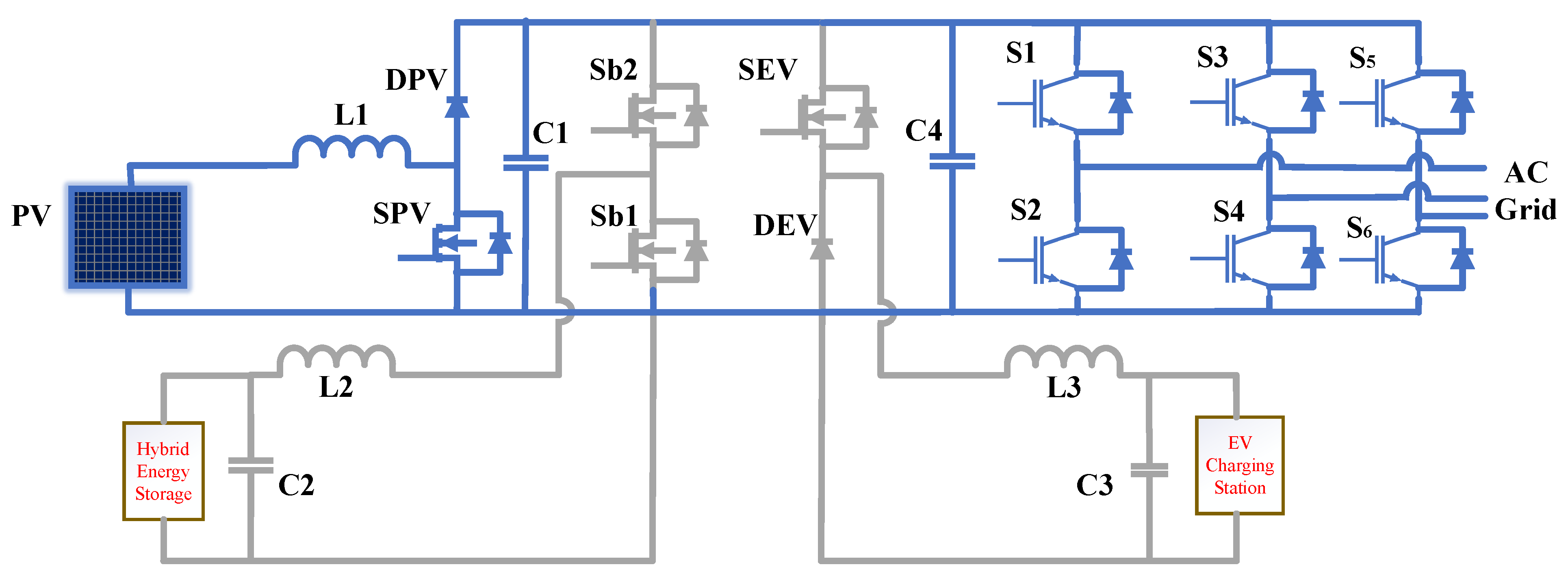
2. Modeling of EV Extra Fast Charging Stations
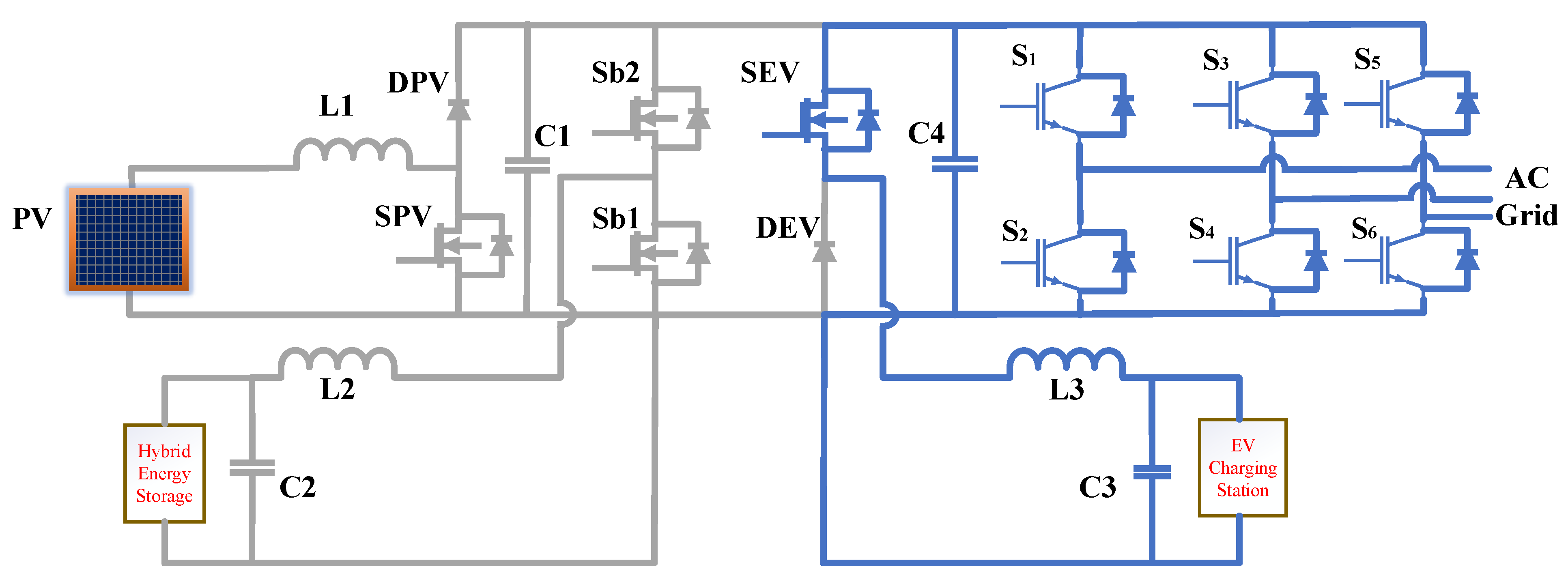
The control scheme and combination of PV power generation, EV charging station, and Hybrid energy storage system (HESS) described in this work provide superior stabilization, including power gap balancing, peak shaving and valley filling, and voltage sag correction. A multiport converter-based EV charging station with PV and HESS is proposed to accomplish the aforementioned goals. Electric vehicle charging stations incorporate solar power, hybrid energy storage systems, and smart grids. The usual architecture of a DC bus charging station with PV integration links the three power sources through three separate converters. The proposed DC bus charging station consists of HESS power sources that share a single DC bus in both directions. HESS is used to balance power excess/insufficient from PV and maintain the DC connection voltage. There are five modes of operation:
  • Mode-I: PV to EV.
  • Mode-II: PV to HES.
  • Mode-III: HESS to EV.
  • Mode-IV: Grid to EV.
  • Mode-V: PV to Grid.

2.1. Mode-I: PV to EV

The switches Spv and SEV are turned on, while Sb1 and Sb2 are turned off (Figure 6).
As can be seen in Figure 6, PV, therefore, provides power directly to the load. The equations at this stage are differentiated and presented in the following form:
i PV = C 1 dv C 1 dt + i EV
C 2 dv C 2 dt = v Bat v C 2 r b i L 2
i EV = C 3 dv C 3 dt + v EV R EV
v C 1 v C 3 = L 3   iL 3 dt
L 2   di L 2 dt = vC 2
where C1, C2, C3 are capacitance of PV port capacitor port capacitor, EV port capacitor and L1, L2, L3 are the inductance of PV port inductor, HESS port inductor, EV load port inductor and r b exhibits the equivalent resistance between VBat and C2, respectively.   i PV ,   i EV , i L 2 , and i L 3 indicate PV panel output, EV load current, inductor L 2 current, and inductor L3 current, respectively. VC1, VC2, VC3, VBat, and VEV represent capacitor C1, C2, C3, HESS output voltage, and charger voltage, respectively. Switch Spv duty cycle may be calculated as
V DC V PV = 1 1 D pv
where VDC is the DC link voltage, VPV is the PV array voltage, and Dpv is the switch Spv duty cycle.

2.2. Mode 2: HESS to EV

HESS is discharged to the EV load when Sb 2 and SEV are active while S PV and Sb1 are inactive, as seen in Figure 7.
The following equations apply while operating in this mode:
i PV = C 1 dv C 1 dt
L 2   iL 2 dt = v DC v C 2
v DC v C 3 = L 3   iL 3 dt
C 2 dv C 2 dt = v Bat v C 2 r b i L 2
i EV = C 3 dv C 3 dt + v EV R EV
where VDC stands for voltage across the DC connection, which is equivalent to the voltage across the capacitor C4. It is possible to get the duty cycle to switch to Sb1 using
V DC V Bat = 1 1 D b 1
VDC, VBat, and Db1 are the DC link voltage, HESS voltage, and Sb1 duty cycle.

2.3. Mode 3: PV to HESS

As illustrated in Figure 8, the HESS is charged from the PV surplus energy when Sb2 is turned on while Sb1, S pv , and SEV are turned off.
The equations in this mode may be stated as follows:
i PV = C 1 dv C 1 dt i L 2
L 2   iL 2 dt = v C 1 + v DC v C 2
L 3   iL 3 dt = v DC v C 3
C 2 dv C 2 dt = v Bat v C 2 r b i L 2
i EV = C 3 dv C 3 dt + v EV R EV
Calculating the duty cycle of switching Sb2 is as simple as:
V Bat V DC = D b 2
where Db2 is the number of times the switch Sb2 is on. Other Modes include PV to HESS, Grid to EV, and PV to Grid. Table 1 gives a summary of how the other modes, such as PV to HESS, grid to EV, and PV to grid, work. Moreover, the differential equations can be written the same way in Modes 1 through 3 using the same analysis method. In the next section, we will talk about the simulation analysis in more depth.

2.4. Mode 4: Grid to EV

Whenever there is no irradiance and the battery State of charge (SOC) is 0% in that case, the grid will supply to the EV charging station as shown in Figure 9. In this mode, all the switches are in OFF condition.

2.5. Mode 5: PV to Grid

If the EV charging station is idle, no vehicle is charged and the battery SOC is 100% in that criterion. The PV is to supply the power to the grid as shown in Figure 10. In this mode the SPV switch is ON and the remaining switches are in OFF Condition.

3. Control Techniques
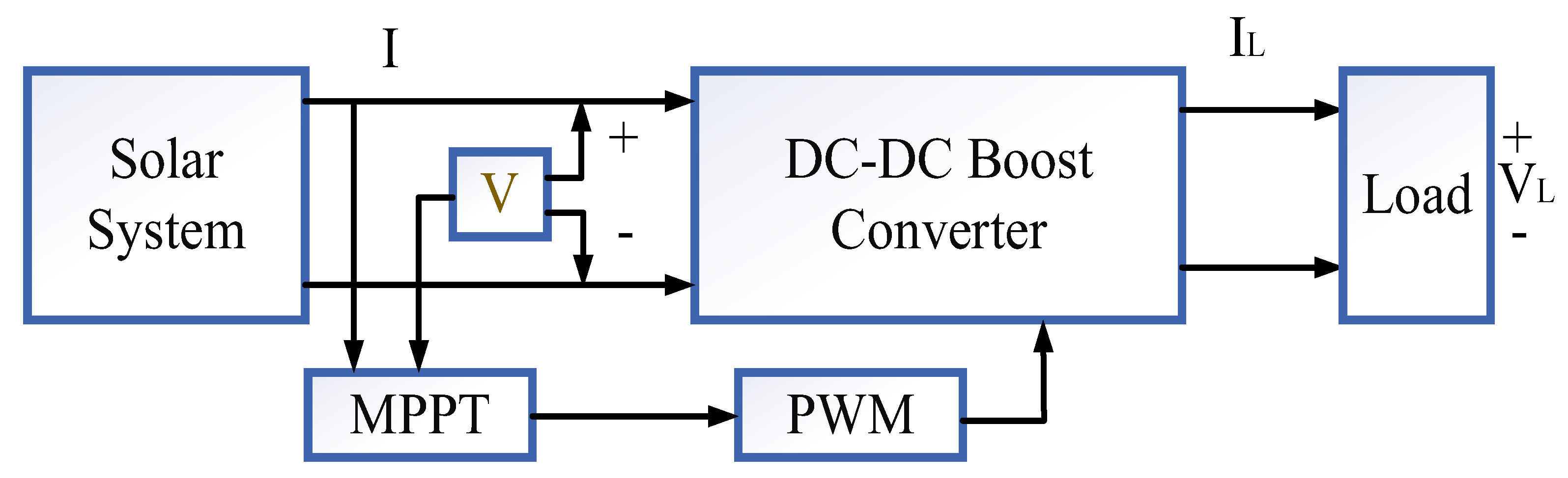
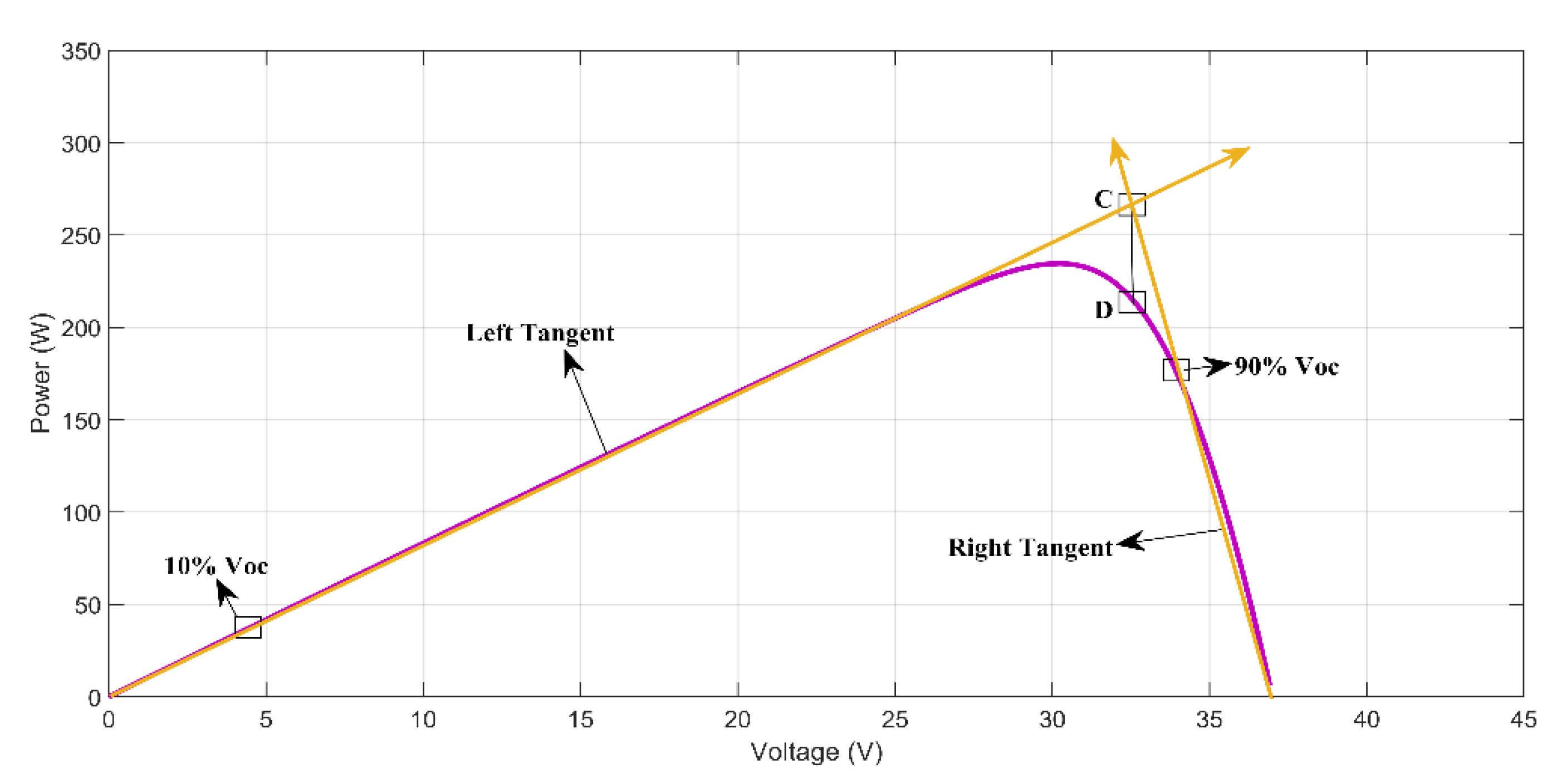
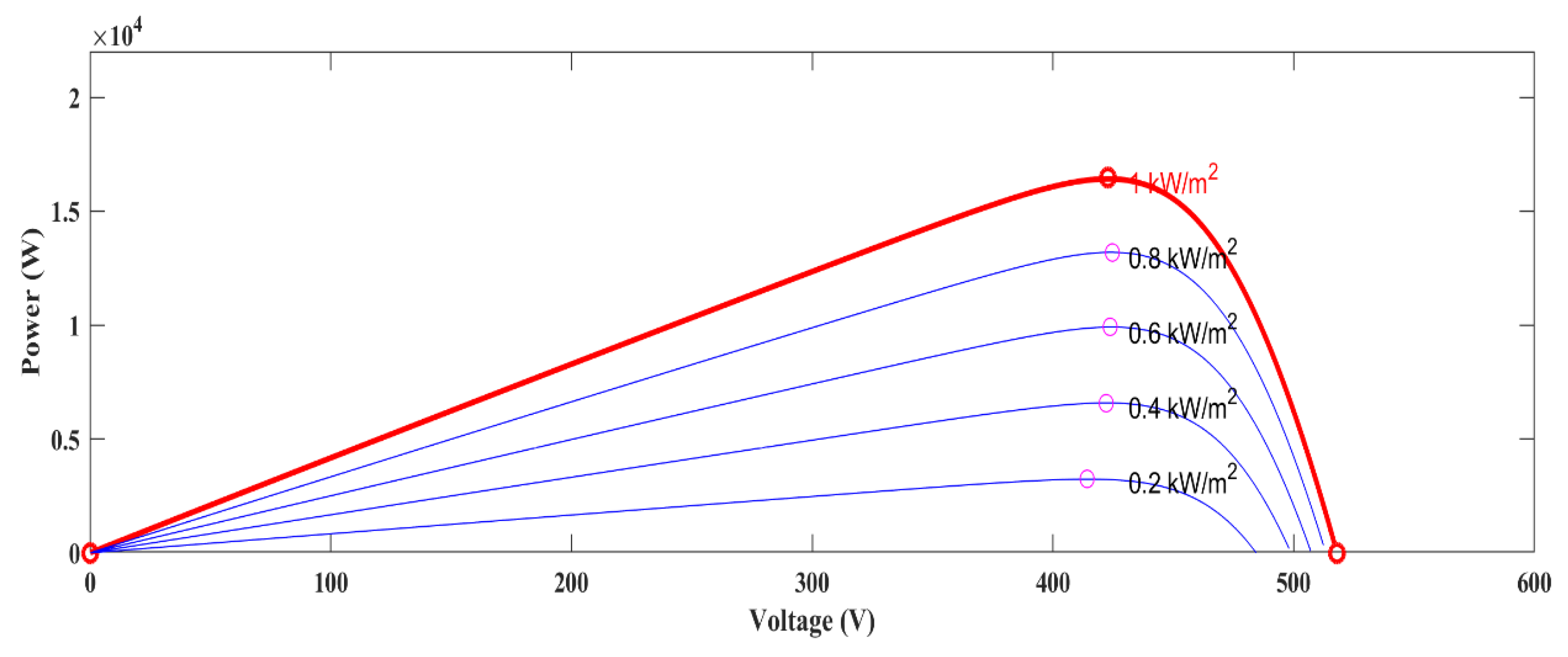
3.1. PV Design

The PV panel is made up of several interconnected PV cells and using MPPT techniques generates the pulses to the DC-DC converter as shown in Figure 11. These are coupled in a series to provide a high output voltage, and are connected in parallel to produce a significant output current [27]. High-efficiency Suntech Power STP235-20/Wd solar panels are used in this study due to their 16% solar cell conversion efficiency [28]. Figure 12 shows the equivalent circuit of a PV panel with a single diode. The I-V characteristic equation, written as [29], is affected by temperature and irradiance.
I = I SC   { 1 k 1 ( e ( v K 2 VDC ) ) 1 }
where I SC = Short circuit current (A),
V = PV panel output voltage (V),
V OC = open circuit voltage (V),
I = PV panel output current (A),
K1 and K2 are the coefficients defined using the below equations
K 1 = ( 1 I M I SC ) e ( V M K 2 VDC )
K 2 = ( V M V DC 1 ) ln ( 1 I M I SC )
where the current and voltage at maximum power point (MPP) are denoted by IM and VM respectively. P-V and I-V characteristics of the PV panel at a temperature of 25 degrees Celsius and at various irradiances exhibit P-V and I-V characteristics at a constant irradiance of 1000 W/m2 with varying temperatures. The amount of electricity produced by the PV panel is expressed as
P = V I SC { 1 K 1 ( e ( V K 2 VDC ) 1 ) }
In photovoltaic systems, the PV panel and the load are separated from one another via an intermediary DC-DC boost converter. According to the Greatest Power Transfer Theorem, the maximum amount of power is transferred from the source to the load when the impedance of the source is equal to the impedance of the load. Adjusting the impedance that exists between the source and the load allows for the boost converter to be modified in order to maximize the amount of power that can be pulled from the solar panel. Negative currents are eliminated thanks to the inclusion of a diode in the system, and high frequency harmonic components are reduced thanks to the inclusion of a filter inductor and capacitor. It is possible to express the voltage gain of the converter as
V out v in = 1 1 d
where d represents the duty cycle.
To overcome the shortcomings of previous methods, this paper presents a Linear Tangent-based MPPT (LTP & O). Step-1: The proposed MPPT involves projecting tangents across the P-V curve; Step-2: Involves estimating the MPP based on the P-V curve; and Step-3: Involves perturbing the estimated MPP to obtain the true MPP. To calculate the voltage derivative of power, we have
P I ( v ) = 1 K 1   I SC   V K 2 V OC e ( v K 2 VOC )
Step-1: Assume that the PV curve has two points, a and b, at 10% and 90% VOC, respectively, denoted as (Va, P(Va)) and (Vb, P(Vb)). The notation of tangents that intersect at these places is
T a ( v ) P   ( V a ) = P I ( V a ) ( V V a )
T b ( v ) P   ( V b ) = P I ( V b ) ( V V b )
where Ta(V) has a slope of PI(Va) and Tb(V) has a slope of PI (Vb). Since PI(Va) > 0 and PI(Vb) 0, the two tangents will meet at a point C if and only if the slopes of the tangents are positive. As can be seen in Figure 13, point D on the PV curve corresponds to the intersection point C.
Step-2: The abscissa at point D is shown as a function of the tangents’ slope.
D = P ( v b ) P ( V a ) + P I ( V a ) × V a P I ( V b ) × V b P I ( V a ) P I ( V b )
Calculating the MPP through tangents to the PV curve yields the value D.
Step-3: The measured voltage and power at point D are disturbed relative to a 0.02 VOC step size reference to obtain the precise MPP on the P-V curve. The MPPT’s suggested workflow is shown in Figure 14. The suggested technique has been shown to improve upon previous approaches in terms of accuracy, efficiency, steady state performance, and dynamic performance of the simulation results.

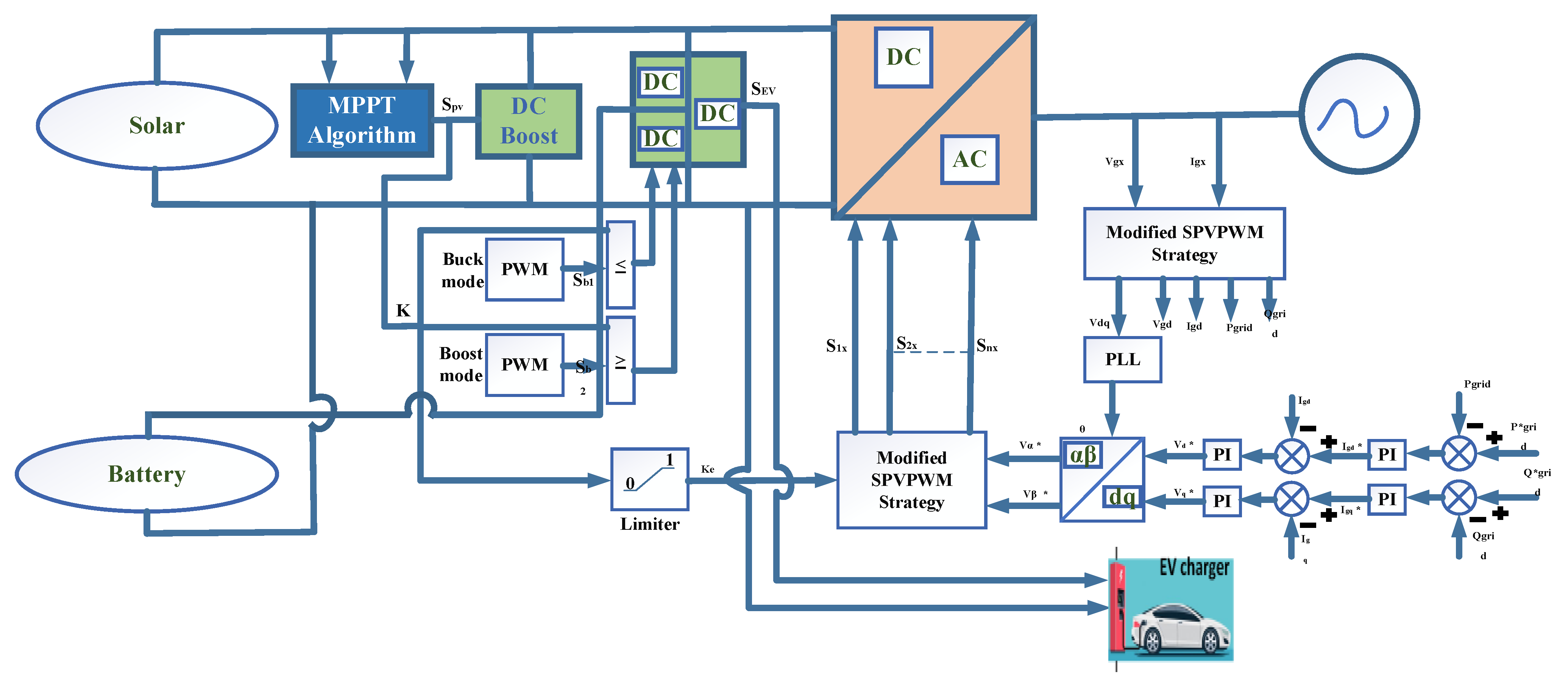
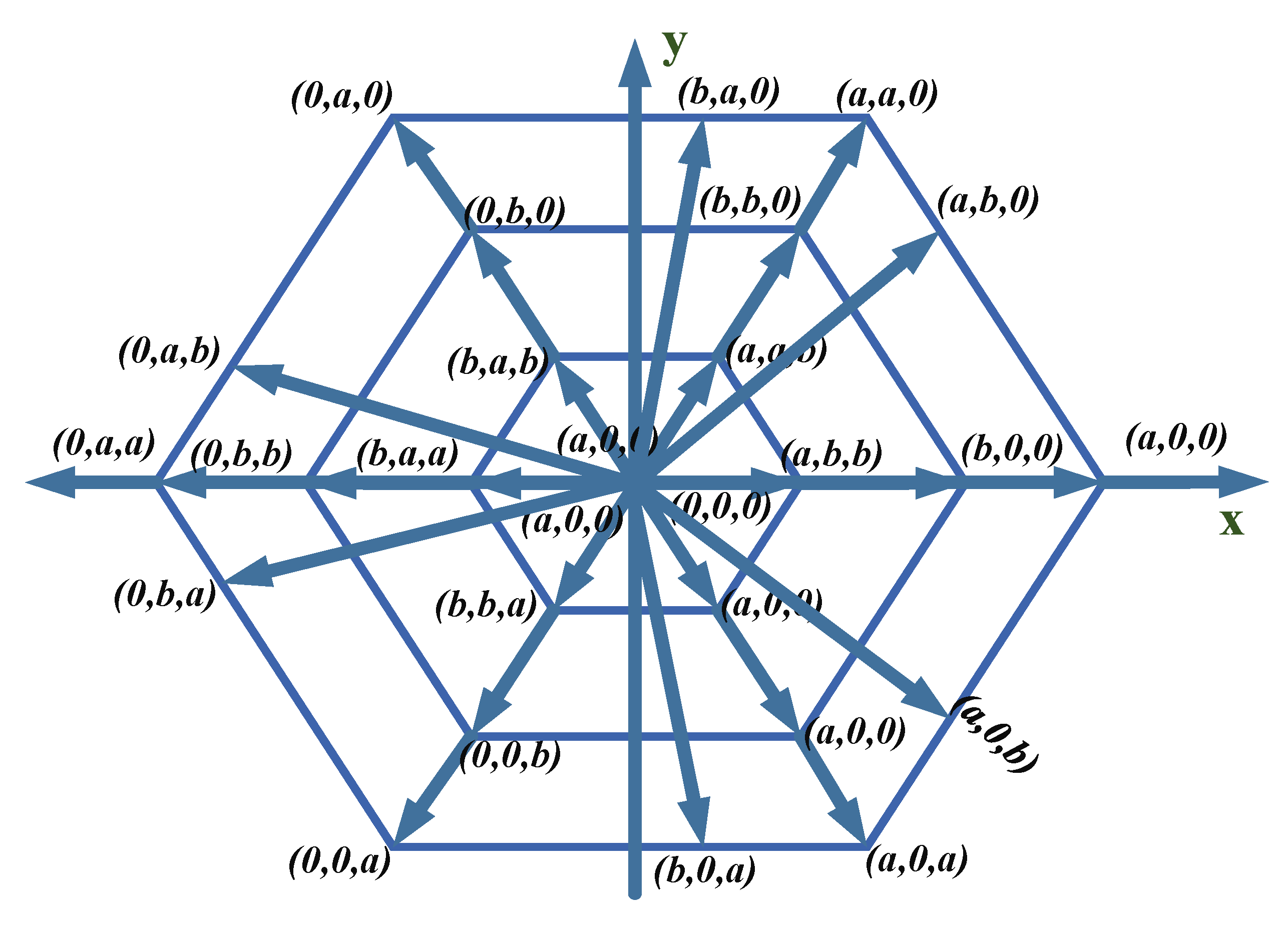
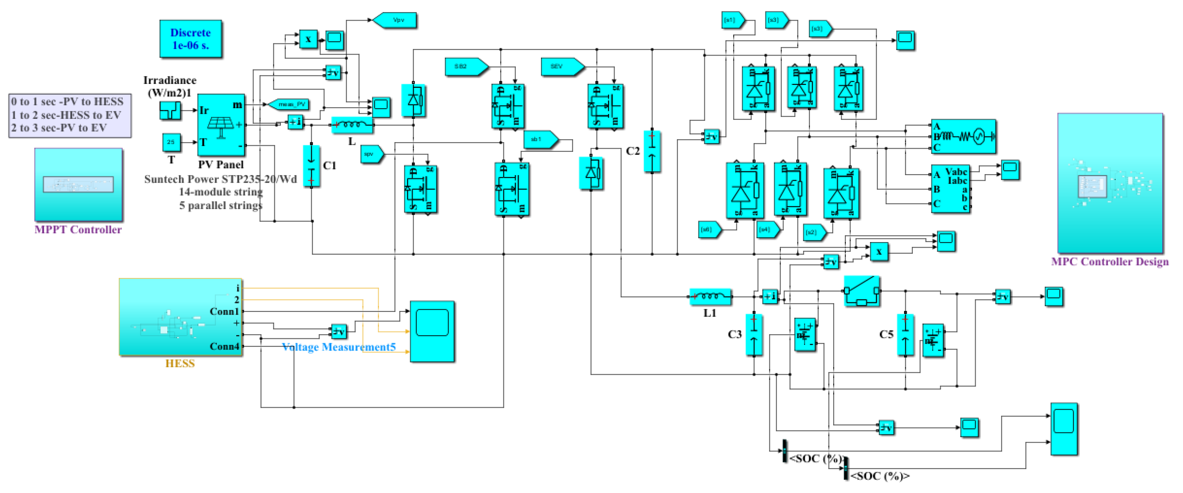
3.2. Multiport Converter Controller Schema

The objective of the proposed configuration is to make PV and battery power supply highly efficient. Since the typical three-level converter is derived from the MPC design, active power regulation of the MPC may be likened to voltage balancing. By regulating the ratio of positive to negative small vectors in SVPWM, three-level converters are always voltage balanced. The method used to achieve voltage balancing related the process achieving to the active power regulation of the two capacitors. This gives us an indication that altering the proportion of positive to negative tiny vectors in the modulation approach can also be used to regulate the power of the PV and batteries for the MPC. To control the switching pulses, a control schema is developed, as shown in Figure 15
The injected AC grid current is regulated using the standard P/Q control. On the DC side, MPPT or another PV power management algorithm, such as the constant power production method [30], can be used to control the active power of PV. Both PV power and AC-grid power may influence the battery’s active power. The essential components required to achieve the suggested control logic are underlined based on the above approach.
The PV power control loop’s output parameter is F, and is used to monitor the ratio of positive to negative small vectors and Fc (0 ≤ Fc ≤ 1). When F is compared to a triangular carrier that ranges from −1 to 0, the driving signal for switch S1 is produced, and when F is compared to a triangular carrier that ranges from 1 to 2, the driving signal for switch S2 is produced. As described in Section 2, the system operates in several modes depending on the value of F. The proposed configuration can accomplish the objective of high-efficiency active power control based on the aforementioned cooperative control technique for the MPC and DPPC. A further essential component is the SVPWM strategy, which will be thoroughly discussed in the next sections, along with the associated power control capacity. Figure 16 represents the Voltage Space Vector for Multiport Converter.
Active power regulation of the PV and batteries is implemented by the MPC using a modified version of the SVPWM approach. The switching operation specifies the midway voltage of each switching-leg, indicated by the switching variable Sx (x = a, b, c). If S1x, S2x, and S3x are on while S4x and S5 are off, then Sx is defined as h. When S2x and S3x are activated and S1x and S4x are deactivated, respectively, then Sx is defined as l. When S3x and S4x are activated and S1x and S2x are deactivated, vxn = 0 and Sx is defined as 0. Combining the switching variables from the three stages yields the following definition of the switching states: (Sa,Sb,Sc). Since the PV and battery voltages are variable, all voltage vectors shift when a and b are adjusted. Different mode of switching sequence as mentioned in Table 2. In particular, the red solid line represents the positive small vector, while the blue solid line represents the negative small vector, and they no longer overlap outside of the range of values represented by b = a/2. As a result, there is asymmetry across the whole space vector diagram.
The proposed design may interface with 2 DC ports and single AC port simultaneously and accomplish variable power regulation among these ports, according to theoretical analysis. The DC-DC converter between the two DC ports has a lower power rating and higher conversion efficiency. The validity of the HESS integrated PV systems has been established in this paper. Moreover, hybrid energy systems can utilize the same principles as this paper.

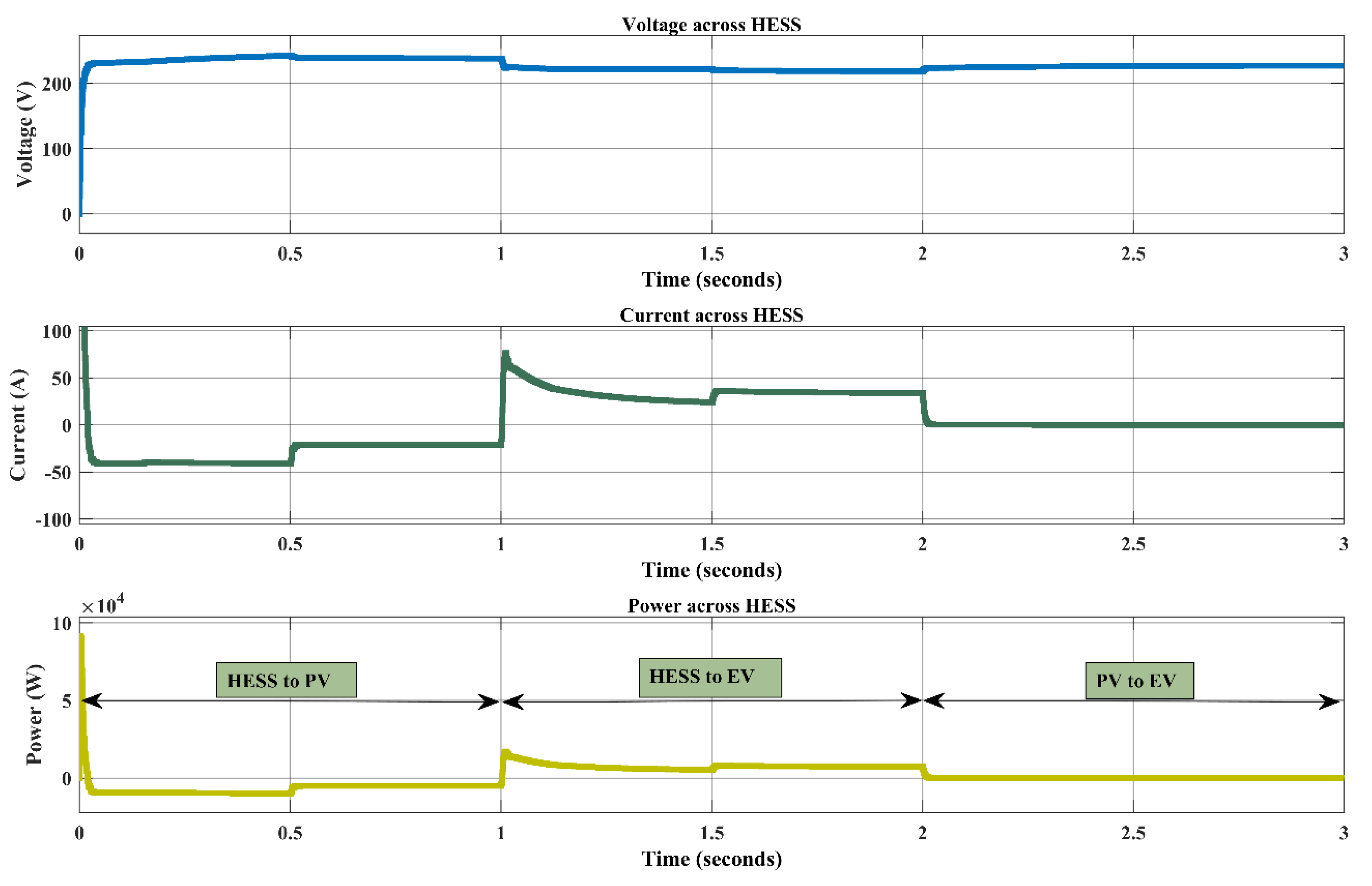
4. Simulation Results

The entire circuit diagram is designed in MATLAB Simulink and operates all the modes and represents the corresponding modes output waveforms below. PV module characteristics as shown in Figure 17 below.
This work explains the three modes of operation based on the availability of solar voltage. In Mode 1: PV supplies the power to HESS, Mode 2: HESS supplies the power to EV terminals, and Mode 3: PV supplies the power to EV terminals. To track the maximum power at solar, a modified Tangent-based MPPT algorithm will be implemented to achieve stable power to the load. As shown in the Figure 13 at point D maximum power will be generated. For solar output is connected with HESS, EV, and Grid. With reference to the Vpv, the switching can be operated. At times 0 to 1 sec, HESS (Batteries and capacitor banks) will start the charging with the help of solar energy when the EV charging station is in ideal condition. Once HESS soc is 100% fully charged and the PV has no irradiance and EV requires the power to charge the EV battery in that time, the HESS will supply the power to EV terminal at 1 to 2 sec. If the HESS soc is 0% and the PV has surplus power, the EV terminal needs electricity to charge the EV battery; in that case, the PV is directly supplied to the EV terminal at 2 to 3 sec. If PV and HESS are not in a position to supply the power to EV terminal, but the EV terminal has required power to charge the EV battery, the grid will supply the power. Grid to EV supplies implemented a SVPWM techniques because the grid has AC and EV has DC fast charging. To achieve stability, better efficiency implemented a modified SVPWM method. Corresponding results are mentioned below. Simulink diagram of the proposed method as shown in Figure 18.
Simulation results are shown as below with respect to different conditions like Mode_1: PV to HESS, Mode_2: HESS to EV; and Mode_3: PV to EV charging station. Figure 19, Figure 20, Figure 21, Figure 22, Figure 23 and Figure 24 represents the PV Voltage, Current and Power at an irradiance of [0.5, 0.8, 1, 0.8, 0.9] ∗ 1000, Across the Hybrid energy storage system, SOC (%) across the battery, EV Terminal Voltage, Current, and Power, two vehicles at a time at an Extreme Fast charging station and Grid DC Voltage respectively.
The below Table 3 represents the comparison of the proposed Multiport with its counterpart MPPT Algorithms and in Table 4 we mentioned the PV Module and HESS parameters. Figure 25 represents the Efficiency comparison of different MPPT with converter models.

5. Conclusions

This study suggests a multiport converter topology by integrating with renewable energy resources such as PV and HESS. HESS is incorporated to maintain stable and balanced PV production and EV charging demands. Additionally, to obtain maximum power at PV, a novel MPPT approach based on perturb and observation with linear tangents was developed. In comparison to conventional approaches, it provides higher efficiency of 99.79% without any output power fluctuations and superior precision, tracking speed, and efficiency. This research proposes a multi-port DC-DC converter (MPC) with modified differential power processing DC-DC converter (DPPC) for rapid charging stations with PV, HESS, and smart grid systems to stabilize power fluctuations. For the MPC, a modified SVPWM system is developed for bidirectional power flow from Grid to EV charging station without voltage fluctuations. The majority of active power from smart grid, HESS, and PV may be regulated by the MPC. PV production, HESS, and EV charging increase the power grid’s reliability. Investigated are various functioning modes and their advantages. According to simulation studies, PV-to-EV, PV-to-HESS, and HESS-to-EV modes may increase efficiency by 5.67%, 4.466%, and 6.00%, respectively. Limitation of this work is mainly developed for PV to EV and HESS system with moderate power ratings. Due to this, the suggested configuration has certain appealing advantages, such as being more integrated, efficient, and economical, and it is a good choice for real-world applications, including HESS integrated PV systems, micro-grids, and so forth.
Future Scope: The multistage or multi-output DC-DC converter provide different ratings power supply for DC appliances. Bidirectional power flow from smart grid to EV and HESS with suitable converter at grid side with high efficiency is future prospective. The aircraft would require a high charging power due to their massive onboard batteries. Charge-Point has unveiled a 2-MW charger design for electric aircraft. Due to the high-power consumption of these chargers, HESSs can play an important role in these DC fast charging systems.

Author Contributions

J.S. and K.S.K. contributed to the paper as follows: study conception, data collection, analysis, design, and implementation of the results of the research and to the writing of the final version of the manuscript. All authors have read and agreed to the published version of the manuscript.

Funding

This research received no external funding.

Data Availability Statement

Not applicable.

Conflicts of Interest

The authors declare no conflict of interest.

References

  1. Rajendran, G.; Vaithilingam, C.A.; Misron, N.; Naidu, K.; Ahmed, R. A comprehensive review on system architecture and international standards for electric vehicle charging stations. J. Energy Storage 2021, 42, 103099. [Google Scholar] [CrossRef]
  2. Lee, J.-Y.; Kim, Y.-K.; Lee, C.-K.; Rhee, Y.-H. A study on the calculation of GHG emission for domestic railroad transport based on IPCC guideline. J. Korean Soc. Railw. 2012, 15, 408–412. [Google Scholar] [CrossRef]
  3. Sweeting, W.J.; Hutchinson, A.R.; Savage, S.D. Factors affecting electric vehicle energy consumption. Int. J. Sustain. Eng. 2011, 4, 192–201. [Google Scholar] [CrossRef]
  4. Jenn, A.; Laberteaux, K.; Clewlow, R. New mobility service users’ perceptions on electric vehicle adoption. Int. J. Sustain. Transp. 2018, 12, 526–540. [Google Scholar] [CrossRef]
  5. Bhatia, K.K.; Riddell, W.T. Identifying and modeling key trade-offs between hydrogen fuel cell and electric vehicles. Int. J. Sustain. Eng. 2016, 9, 215–222. [Google Scholar] [CrossRef]
  6. Li, L.; Wang, Z.; Gao, F.; Wang, S.; Deng, J. A family of compensation topologies for capacitive power transfer converters for wireless electric vehicle charger. Appl. Energy 2020, 260, 114156. [Google Scholar] [CrossRef]
  7. Akeyo, O.M.; Rallabandi, V.; Jewell, N.; Ionel, D.M. The Design and Analysis of Large Solar PV Farm Configurations with DC-Connected [21] Battery Systems. IEEE Trans. Ind. Appl. 2020, 56, 2903–2912. [Google Scholar] [CrossRef]
  8. Ronanki, D.; Kelkar, A.; Williamson, S.S. Extreme fast charging technology—Prospects to enhance sustainable electric transportation. Energies 2019, 12, 3721. [Google Scholar] [CrossRef]
  9. Rallabandi, V.; Lawhorn, D.; He, J.; Ionel, D.M. Current weakening control of coreless afpm motor drives for solar race cars with a three-port bi-directional dc/dc converter. In Proceedings of the 2017 IEEE 6th International Conference on Renewable Energy Research and Applications (ICRERA), San Diego, CA, USA, 5–8 November 2017; pp. 739–744. [Google Scholar]
  10. Liu, Y.; Tang, Y.; Shi, J.; Shi, X.; Deng, J.; Gong, K. Application of small-sized smes in an ev charging station with dc bus and pv system. IEEE Trans. Appl. Supercond. 2015, 25, 1–6. [Google Scholar] [CrossRef]
  11. Wang, J.; Sun, K.; Xue, C.; Liu, T.; Li, Y. Multi-Port DC-AC Converter with Differential Power Processing DC-DC Converter and Flexible Power Control for Battery ESS Integrated PV Systems. IEEE Trans. Ind. Electron. 2021, 69, 4879–4889. [Google Scholar] [CrossRef]
  12. Zhu, H.; Zhang, D.; Zhang, B.; Zhou, Z. A nonisolated three-port dc-dc converter and three-domain control method for pv-battery power systems. IEEE Trans. Ind. Electron. 2015, 62, 4937–4947. [Google Scholar] [CrossRef]
  13. Zhang, Y.; He, J.; Ionel, D.M. Modeling and control of a multiport converter based EV charging station with PV and battery. In Proceedings of the 2019 IEEE Transportation Electrification Conference and EXPO (ITEC), Detroit, MI, USA, 19 June 2019; IEEE: Piscataway, NJ, USA, 2019; pp. 1–5. [Google Scholar]
  14. Mahmood, H.; Michaelson, D.; Jiang, J. Strategies for Independent Deployment and Autonomous Control of PV and Battery Units in Islanded Microgrids. IEEE J. Emerg. Sel. Topics Power Electron. 2015, 3, 742–755. [Google Scholar] [CrossRef]
  15. Karimi, Y.; Oraee, H.; Guerrero, J.M. Decentralized Method for Load Sharing and Power Management in a Hybrid Single/Three-Phase-Islanded Microgrid Consisting of Hybrid Source PV/Battery Units. IEEE Trans. Power Electron. 2017, 32, 6135–6144. [Google Scholar] [CrossRef]
  16. Merabet, A.; Ahmed, K.T.; Ibrahim, H.; Beguenane, R.; Ghias, A.M.Y.M. Energy Management and Control System for Laboratory Scale Microgrid Based Wind-PV-Battery. IEEE Trans. Sustain. Energy 2017, 8, 145–154. [Google Scholar] [CrossRef]
  17. Yi, Z.; Dong, W.; Etemadi, A.H. A Unified Control and Power Management Scheme for PV-Battery-Based Hybrid Microgrids for Both Grid-Connected and Islanded Modes. IEEE Trans. Smart Grid 2018, 9, 5975–5985. [Google Scholar] [CrossRef]
  18. Narayanan, V.; Kewat, S. Real-Time Implementation of CLMS Algorithm in 3P4W Solar PV-BES-Based Microgrid System. IEEE Trans. Ind. Appl. 2021, 57, 795–804. [Google Scholar] [CrossRef]
  19. Devassy, S.; Singh, B. Performance Analysis of Solar PV Array and Battery Integrated Unified Power Quality Conditioner for Microgrid Systems. IEEE Trans. Ind. Electron. 2021, 68, 4027–4035. [Google Scholar] [CrossRef]
  20. Szymanski, J.R.; Zurek-Mortka, M.; Wojciechowski, D.; Poliakov, N. Unidirectional DC/DC converter with voltage inverter for fast charging of electric vehicle batteries. Energies 2020, 13, 4791. [Google Scholar] [CrossRef]
  21. Jha, M.; Blaabjerg, F.; Khan, M.A.; Bharath Kurukuru, V.S.; Haque, A. Intelligent control of converter for electric vehicles charging station. Energies 2019, 12, 2334. [Google Scholar] [CrossRef]
  22. Rafi, M.A.; Bauman, J. A comprehensive review of DC fast-charging stations with energy storage: Architectures, power converters, and analysis. IEEE Trans. Transp. Electrif. 2020, 7, 345–368. [Google Scholar] [CrossRef]
  23. Zheng, L.; Kandula, R.P.; Divan, D. Multiport Control with Partial Power Processing in Solid-State Transformer for PV, Storage, and Fast-Charging Electric Vehicle Integration. IEEE Trans. Power Electron. 2022, 38, 2606–2616. [Google Scholar] [CrossRef]
  24. Somakumar, R.; Kasinathan, P.; Monicka, G.; Rajagopalan, A.; Ramachandaramurthy, V.K.; Subramaniam, U. Optimization of emission cost and economic analysis for microgrid by considering a metaheuristic algorithm-assisted dispatch model. Int. J. Numer. Model. Electron. Netw. Devices Fields 2022, 35, e2993. [Google Scholar] [CrossRef]
  25. Valedsaravi, S.; El Aroudi, A.; Martínez-Salamero, L. Review of Solid-State Transformer Applications on Electric Vehicle DC Ultra-Fast Charging Station. Energies 2022, 15, 5602. [Google Scholar] [CrossRef]
  26. Hua, C.; Shen, C. Comparative study of peak power tracking techniques for solar storage system. In Proceedings of the APEC ’98 Thirteenth Annual Applied Power Electronics Conference and Exposition, Anaheim, CA, USA, 15–19 February 1998; pp. 679–685. [Google Scholar]
  27. KC200GT High Efficiency Multicrystal Photovoltaic Module Datasheet Kyocera. Available online: http://www.kyocera.com.sg/products/solar/pdf/kc200gt.pdf (accessed on 22 July 2022).
  28. Xiao, W.; Dunford, W.G.; Capel, A. A novel modeling method for photovoltaic cells. In Proceedings of the 2004 IEEE 35th Annual Power Electronics Specialists Conference (IEEE Cat. No.04CH37551), Aachen, Germany, 20–25 June 2004. [Google Scholar]
  29. Kota, V.R.; Bhukya, M.N. A novel linear Tangents based P&O scheme for MPPT of a PV system. Renew. Sustain. Energy Rev. 2017, 71, 257–267. [Google Scholar]
  30. Ahmed, K.Y.; Bin Yahaya, N.Z.; Asirvadam, V.S.; Saad, N.; Kannan, R.; Ibrahim, O. Development of power electronic distribution transformer based on adaptive PI controller. IEEE Access 2018, 6, 44970–44980. [Google Scholar] [CrossRef]
  31. Algazar, M.M.; AL-monier, H.; El-Halim, H.A.; El Kotb Salem, M.E. Maximum power point tracking using fuzzy logic control. Int. J. Electr. Power Energy Syst. 2012, 39, 21–28. [Google Scholar] [CrossRef]
  32. Abdelsalam, A.K.; Massoud, A.M.; Ahmed, S.; Enjeti, P.N. High-performance adaptive perturb and observe MPPT technique for photovoltaic-based microgrids. IEEE Trans. Power Electron. 2011, 26, 1010–1021. [Google Scholar] [CrossRef]
  33. Muthuramalingam, M.; Manoharan, P.S. Comparative analysis of distributed MPPT controllers for partially shaded stand-alone photovoltaic systems. Energy Convers. Manag. 2014, 86, 286–299. [Google Scholar] [CrossRef]
  34. Jubaer, A.; Salam, Z. An improved perturb and observe (P&O) maximum power point tracking (MPPT) algorithm for higher efficiency. Appl. Energy 2015, 150, 97–108. [Google Scholar]
Figure 1. Greenhouse gas emissions by sector as of 2022.
Energies 16 01521 g001
Figure 2. Electric vehicle volumes (thousands) on the road in 2020–2022.
Energies 16 01521 g002
Figure 3. Fast public charging stations globally.
Energies 16 01521 g003
Figure 4. DC-Coupled Battery Energy Storage System Integrated PV and Grid System.
Energies 16 01521 g004
Figure 5. Multiport converter designs, the typical design of EV charging stations with integrated PV.
Energies 16 01521 g005
Figure 6. Power flow from PV to EV Charging station.
Energies 16 01521 g006
Figure 7. Power flow from HESS to EV Charging station.
Energies 16 01521 g007
Figure 8. Power flow from PV to HESS.
Energies 16 01521 g008
Figure 9. Power flow from Grid to EV Charging station.
Energies 16 01521 g009
Figure 10. Power flow from PV to Grid.
Energies 16 01521 g010
Figure 11. Block Diagram for PV System.
Energies 16 01521 g011
Figure 12. Equivalent Circuit PV Panel.
Energies 16 01521 g012
Figure 13. Tangent-based MPP estimation: C is Tangent intersection and D is PV MPP.
Energies 16 01521 g013
Figure 14. Flow chart for LT & O Schema.
Energies 16 01521 g014
Figure 15. Multiport Converter control schema.
Energies 16 01521 g015
Figure 16. Voltage Space Vector for Multiport Converter [11].
Energies 16 01521 g016
Figure 17. PV Module P-V Characteristics.
Energies 16 01521 g017
Figure 18. Simulink diagram of the proposed MPC model.
Energies 16 01521 g018
Figure 19. PV Voltage, Current and Power for different modes of operation at an irradiance of [0.5, 0.8, 1, 0.8, 0.9] ∗ 1000.
Energies 16 01521 g019
Figure 20. Hybrid energy storage system operates for different conditions; Mode_1: PV to HESS, Mode_2: HESS to EV; and Mode_3: PV to EV charging station.
Energies 16 01521 g020
Figure 21. Battery SOC (%) for various modes of operations.
Energies 16 01521 g021
Figure 22. EV Terminal Voltage, Current, and Power different modes of operation.
Energies 16 01521 g022
Figure 23. You can charge two vehicles at a time at an Extreme Fast charging station.
Energies 16 01521 g023
Figure 24. Grid DC Voltage for various modes of operation.
Energies 16 01521 g024
Figure 25. Efficiency comparison of different MPPT with converter models.
Energies 16 01521 g025
Table 1. EV Charging Operating Modes.
S p v S b 1 S b 2 S E V Power Flow
1001PV to EV
1010PV to HESS
0101HESS to EV
0001Grid to EV
1000PV to Grid
Table 2. Modes of Switching Sequence [11].
SwitchesSwitching Operation
(½)XcF0(½)F1(½)F2(1 − (½)) F0(½)F1(½)F2
S1[b/0/0][b/b/0][b/b/b][a/b/b][b/b/b][b/b/0]
S2[b/0/0][a/0/0][a/b/0][a/b/b][a/b/0][a/0/0]
S3[b/0/0][b/b/0][a/b/0][a/b/b][a/b/0][b/b/0]
S4[b/b/0][b/b/b][a/b/b][a/a/b][a/b/b][b/b/b]
S5[b/b/0][a/b/0][a/a/0][a/a/b][a/a/0][a/b/0]
S6[b/b/0][a/b/0][a/b/b][a/a/b][a/b/b][a/b/0]
Table 3. Detailed comparison of the proposed Multiport with its counterpart MPPT Algorithms.
ReferencesMPPT TechniquesConverter TypeRequired SensorsResponse Time (ms)Efficiency (%)
[31]Short-Circuit Current (SCC)CUK Converter2Amperemeter8083
[32]P&OBoost Converter1Voltmeter 1 Amperemeter7688
[33]PSO-ANFIS P&O-ANFIS ANNBoost Converter1Voltmeter 1 Amperemeter1985–97
[34]Modified P&OBoost ConverterSensor-less1799.7
[29]Linear Tangent based Perturbation & Observe Boost Converter1Voltmeter 1 Amperemeter1999.75
This WorkModified Linear Tangent based Perturbation & Observe Multiport ConverterSensor-less1299.79
Table 4. PV Module and HESS parameterss.
Suntech Power STP235-20/Wd-SpecificationsHybrid Energy Storage System Specifications
PMax = 235.258 WLithium-Ion battery:Super Capacitors
VOC = 37.0 VNominal Energy = 3.3 KWNominal Energy = 3.3 KW
ISC = 8.35 ADesired Voltage = 220 VDesired Voltage = 220 V
IM = 7.79 ARated Capacity = 15Rated Capacitor = 470 uF
VM = 30.2 VmaxSOC (%) = 80Temperature = 40 °C
Battery Response = 1 sec
Disclaimer/Publisher’s Note: The statements, opinions and data contained in all publications are solely those of the individual author(s) and contributor(s) and not of MDPI and/or the editor(s). MDPI and/or the editor(s) disclaim responsibility for any injury to people or property resulting from any ideas, methods, instructions or products referred to in the content.

