Abstract
A single independent voltage source ( or ) is used to regulate the speed of an E-vehicle (EV) with the same interval of switching pulses to generate different voltage ratios by charging/discharging the flying capacitors using a novel single-input multi-output (SIMO) DC-DC switched capacitor converter. In this work, various speed transmissions are generated for controlling the speed of EVs. The selected and regulated battery voltage are generated using the SIMO DC-DC converter. The proposed converter is used to generate seven different transmission in total, of which four transmissions are used for motoring (forwarding operation) and the other three transmissions act as regenerative braking. For motoring operation, the battery, fuel cell, and photovoltaic cell are used as a sources of energy, and for the regenerative braking, the regenerated voltage is fed back to store the battery. The SIMO DC-DC converter is used to support electronic accessories, such as LED lights, the EV audio system and other accessories, including mobile and laptop battery charging. The energy recovered during regenerative braking is used to charge the battery via a proposed SIMO DC-DC converter for different speed transmissions. In addition, simulation, modeling, and analysis are used to validate the proposed system. It is intended for a fixed voltage of 12 V and output voltages ranging from 12 to 48 V. The PSIM simulation tool is used to validate the system. The validation demonstrates that the suggested converter shows good evidence for both braking and regenerative braking operations.
1. Introduction
In recent years, the E-vehicle (EV) has played a vital role in the means of transport. According to the International Transport Forum [1], due to the rapid increase in urbanization, CO emissions will increase around 60% by 2050, causing global warming. One of the main reasons for the introduction of EVs is the concern about greenhouse gas emissions and their contribution to the reduction of such harmful gas emissions. EVs have a lot of potential to reduce greenhouse gas emissions. Basically, two types of EVs are used in the market: plug-in hybrid (PHEV) is majorly used, where internal combustion engines are used to run the vehicle along with EV system. An electric vehicle’s fundamental components are a battery, a DC-DC converter, a power electronic controller, and a traction motor. Similarly, smart vehicle are developed to overcome the conventional EV [2]. The smart vehicle are used with IoT-based control, and renewable- and nonrenewable-based input sources to the EVs are currently used. Additionally, mechanical speed control is widely used and studied based on clutch control [3,4], automatic transmission control [5,6], and gear shift control [3]. For efficient regenerative braking and speed transmission control, electrical control is preferred and fast. In this work, an electric-based DC-DC speed control technique is used for controlling the speed of the E-vehicle. The DC-DC converter is used for controlling the speed of the EV, and it is used for controlling other electronic devices in the EV system. For simplicity, the E-bike is considered for the discussion. For controlling the DC motor [7], a DC-DC converter is required. The switched capacitor (SC) converter possess more advantages as compared to the conventional converters because the converter only uses switches and capacitors for the conversion operation, and these converters provides high efficiency and maximum target voltages; the inductor-based converters [8] provide a good solution but have some limitations, such as EMI issues and iron losses. SC converters are widely used in many applications. High- and medium-power applications can also benefit from these switched capacitor DC-DC topologies. For the efficient conversion of DC to AC power, the output of such DC-DC converters is provided to DC-AC inverters to obtain the AC voltage by regulating the inverter with relevant PWM methods [9,10]. Renewable energy sources are connected to the grid via high- and medium-power DC-DC converters. The general converter topology is considered, i.e., single-input multiple-output (SIMO) switched-capacitor DC-DC converter is designed for speed transmission. In EV, a battery is used for the acceleration of the vehicle using the DC-DC converter, i.e., it converts the fixed DC power from the battery to the variable DC, which can be used by various parts of the circuit and to drive the DC motor in the vehicle. The SC converter is designed in such a way as to maintain the voltage ripple and maintain the negative current [2]. The main advantage of the proposed speed control system controls both the acceleration/deceleration operation for both motoring and regenerative operation also used to control different electronic components in the vehicle. In an electrical vehicle, regenerative braking also helps to extend the vehicle’s range. The kinetic energy is transformed to electrical energy during the regenerative braking cycle [11]. The driving range may be extended by using regenerative braking, which also increases the braking efficiency. Many different types of study have been conducted on regenerative braking in the recent literature [11,12,13], but the four-transmission system completely automatic controller is not mentioned in many of them. A novel four-transmission system for forwarding and regenerative operation is explored in this paper. The suggested system’s regenerative braking technology is shown in Figure 1.
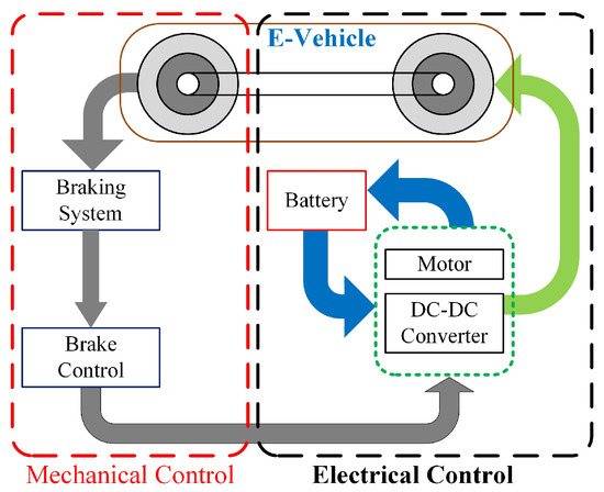
Figure 1.
Configuration of regenerative braking system.
2. Proposed Four-Transmission Converter Control
The SIMO proposed DC-DC converter is illustrated in Figure 2: a switched capacitor (SC) [14] with 4 flying capacitors and 14 bidirectional switches which are connected in series and parallel in the circular path with single source ( or ). Different output nodes can be used to link the numerous outputs (–) to the load. At each node, the output capacitor is connected across each terminal, where the speed transmission varies according to different voltage ratios. Both step-up (acceleration) and step-down (deceleration) voltages are achievable with the proposed converter. This proposed converter is capable of generating the voltage ratios, such as () and (). The motoring and regenerative switching pulses are given in Table 1. The bidirectional switches are driven by two phases with a 50 percent duty cycle ratio. The charging state is phase (, while the discharging condition is phase . The flying capacitor is connected in series and parallel combination to generate different voltage ratios. Different speed transmission are selected according to the voltage ratios given in Table 1 and the speed transmission switching details are also discussed. Here, the input voltage, , is considered as 12 V. For the 1st transmission, the output voltage = = 12 V. Similarly, for the 4th transmission, the output voltage = = 48 V. To generate the different speed transmissions, the following switching sequence needs to be considered. For simplicity, speed transmission is considered. Phase 1 involves charging the capacitors and in parallel with and turning on the switches and . Similarly, in phase 2, the capacitors and are connected in series with the , and the secondary terminal of and are connected to the voltage source; the same capacitor terminal is connected to using the switches and . The modes of operation is followed along with the capacitor C4 to generate transmission. The stored energy is given back to the battery via the proposed converter during regenerative braking. In Table 1, ‘P’ denotes a 50% positive half cycle, ‘N’ denotes a 50% negative half cycle, and ‘1’ denotes a switch that is always on.
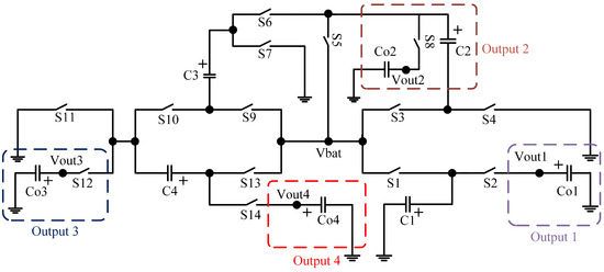
Figure 2.
Circuit of SIMO DC-DC proposed converter.

Table 1.
Acceleration and deceleration of speed transmission switching pattern.
3. Analysis and Modes of Operation
When building a SC converter [15], one of the most essential parameters to consider is equivalent resistance. For the sake of simplicity, voltage ratios of are used in the analysis. Figure 3 and Figure 4 depict the analogous circuit for the voltage ratio . The power loss [8] in any ith operational phase is provided as
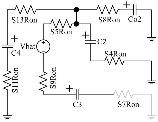
Figure 3.
Equivalent circuit of charging state (4 * ).
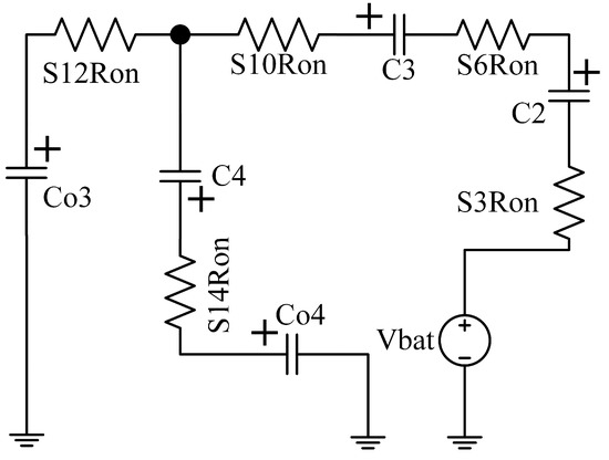
Figure 4.
Equivalentcircuit of discharging state (4 * ).
Assume that all switch resistances are the same and that parasitic effects (ESR) for all flying capacitors are the same. In addition, as compared to the flying capacitor capacitance (, , , ), the filter capacitor capacitance (, , , ) is high. The current equation is given in (2)–(4) using the technique outlined in [16], the charge balance equation, and nodal KCL analysis for phases and as shown below:
The capacitor charging and discharging equation is obtained from Figure 3 and Figure 4, and is given in (5)–(8).
Similar steps are followed for solving for other voltage ratios. The of other voltage ratios is given in Table 2.
Table 2.
Equivalent resistance of four speed transmission.
4. Simulation and Discussion
In this work, only the electrical speed transmission control is designed using existing mechanical braking systems [4,12,13]. The proposed converter is simulated using the PSIM tool, and it is validated using the model which is designed using a bidirectional switch and the parameters of the MAX4678 switches – are R = [17], referring to Figure 2. The load current varies from 2 mA to 1 A at a voltage of 12 V for the different voltage ratios, and the flying capacitor and output capacitor are rated at 22 F with an ESR of 100 m and 220 F with a load resistance of 5 k; the load current ranges from 2 mA to 1 A at a voltage of 12 V. The comparative findings of the model (), simulated (), and theoretical voltages () of the voltage ratio are shown in Table 3. The simulations are carried out under the following scenarios:
Table 3.
Comparison results of , and speed transmission.
- Case 1: Proposed converter outputs (–) are connected to electronic loads.
- Case 2: One of the outputs is connected to EV (motor load), and the remaining outputs are connected to the electronics load.
- Case 3: Regenerative voltage fed back to the .
- Case 4: All the loads are connected to the motor using , and the regenerative voltage is fed back to .
4.1. Case 1
In this scenario, the electronic load is linked to all of the proposed converter’s loads. The output voltage and voltage ripple of the 4 * voltage ratio are shown in Figure 5, with a voltage ripple of 0.1 V. All of the simulated output voltages are almost identical to the model values, as shown in Figure 6. The simulated output voltage of 3 * is 35.97 V, as shown in Figure 7, and it is evident that the simulated output voltage is nearly similar to the model voltages. In addition, the load variation for the suggested converter is shown in Figure 5 by altering the resistance value from 5 k to 1 k for the voltage ratio 4 * . By comparing the findings of (), () and () values that are in excellent agreement with each other, the suggested converter is concluded.
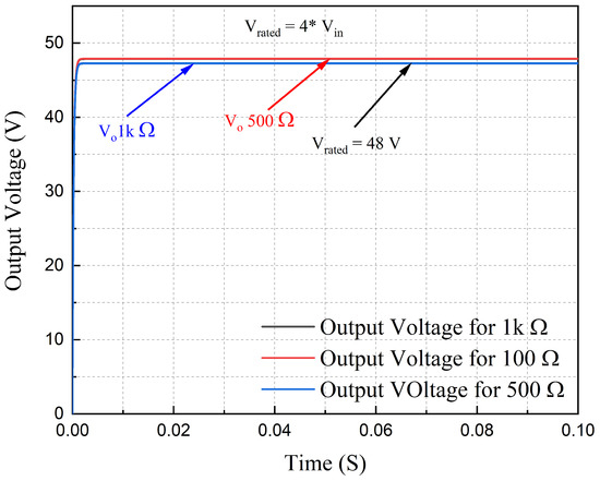
Figure 5.
Different load conditions of simulated output voltage of 4 * .
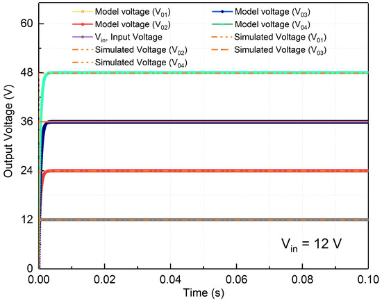
Figure 6.
Model voltage and simulated voltage of SIMO DC-DC converter.
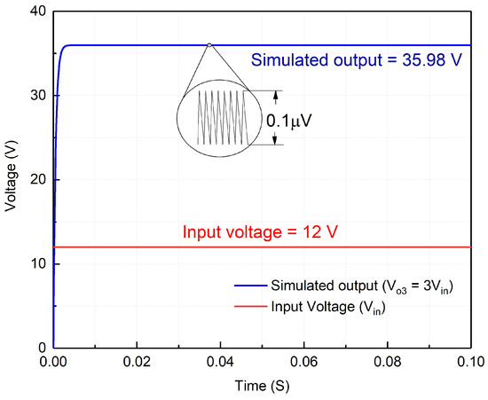
Figure 7.
Simulation of SIMO output voltage of 3 * mode.
4.2. Case 2
The parameters of torque, speed, and the current are assumed using and from the basic E-bike. Assumptions are made for designing the E-vehicle parameters. The parameters are as follows: motor/gear is 3 kg, controller is 0.5 kg, battery is 3 kg and the cyclist is 10 kg. Let us consider the real-time parameters of a bicycle, where the speed, is 5 km/h, is 13 Nm, is 18 W, head wind speed is 1 km/h, and, adding 2 W power to propel, is 20 W. When designing the EV, real-time factors are taken into account. Assume the EV power and torque are constant. Figure 8 depicts the proposed converter’s simulated output voltage when the load is connected to the motor. It provides the efficient results of output voltage of 11.98 V, load current of 1.68 A, torque of 13 Nm, input voltage of 12 V, and speed of 13.6 RPM. From this, it is clear that even when the motor load is connected to the proposed converter, it provides efficient operation.
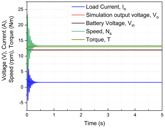
Figure 8.
Simulated output voltage when load is connected as DC motor.
4.3. Case 3
The energy from the EV is supplied back to the source during regenerative braking using the same suggested converter, which will serve as a buck operation for charging the battery utilizing different step-down voltage ratios. Let us consider (0.3 * ) voltage ratios as a regenerative voltage for the simulation and analysis, and the turn on/off switching pulse pattern for the regenerative case is shown in Table 4. If the regenerative voltage is not achieved, the target voltage 12.5 V (predefined voltage for charging a 12 V battery). The SIMO converter selects the different voltage ratios to buck the voltage for charging the battery. Figure 9 displays the simulated output voltage of the regenerative braking of proposed converter.
Table 4.
Regenerative switching pattern of proposed converter.
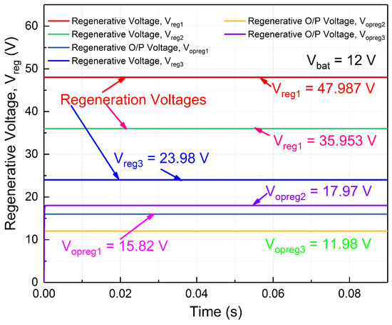
Figure 9.
Simulated output voltage of regenerative braking.
Figure 10 depicts the total efficiency of the proposed converter for motoring and regenerative braking. Table 5 shows the overall comparison of different factors with previous research studies. As a result, the suggested converter has a higher efficiency, fewer switches and capacitors, and lower voltage ripple. In addition, the suggested converter would operate in both forwarding and regenerative modes without requiring any changes to the circuit architecture. In this simulation, the switched capacitor converter provides high efficiency [17] in open-loop conditions as shown in the Figure 10. So the closed-loop system is not necessary for the proposed system for manual transmission. To make a more efficient and speedy operation, closed-loop operation may be considered for automatic switching in Case 3.
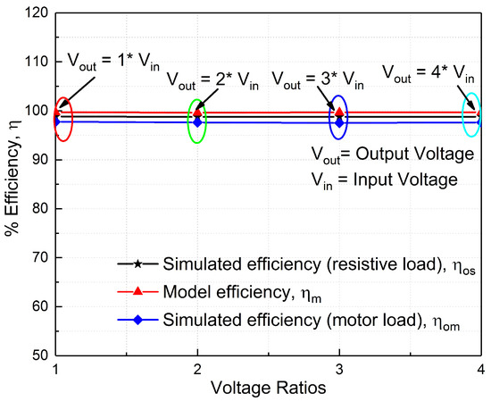
Figure 10.
Efficiency of proposed converter.
Table 5.
Comparison results with other switched capacitor speed controller converter.
4.4. Case 4
In this case, all the output terminal are connected to the motor load for different ratings. Figure 11 shows that all the loads are connected to the motor terminals and the same terminals are used to be fed back to the battery using regenerative braking. Figure 11a shows this for the output 1 voltage. The same motor parameters are used for Case 4. In Figure 11a, the output voltage is almost equal to the model voltage. The voltage for output 1 is 1 * , which is 12 V. Similarly, for the other outputs, the voltages are 24 V, 36 V and 48 V. Almost all the output voltages are equal to the model voltage, which is shown in Figure 11a–d. Additionally, the motor speed is varied according to the proposed converter voltage to vary the speed which is depicted in Figure 11. In this, the torque is a fixed constant for all the cases. From Figure 11, it is clearly noted that even if you connect all the output ports to be parallel to the motor terminals, the proposed system is able to control the speed and the torque of each terminal without lagging the speed and efficiency of the system.
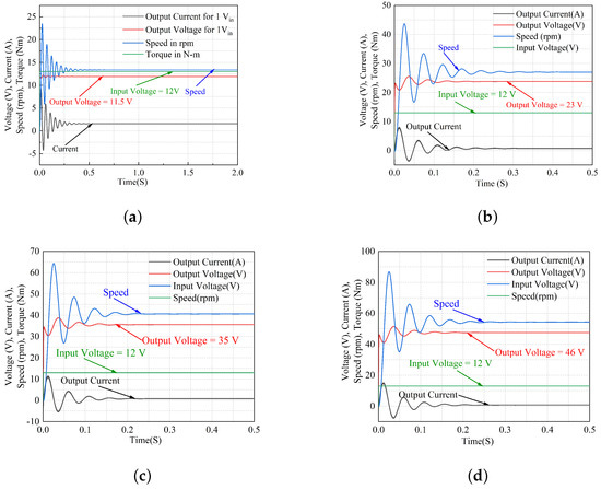
Figure 11.
Simulation Results of SIMO DC-DC converter when all the loads are connected in parallel. (a) Output voltage−1 * . (b) Output voltage−2 * . (c) Output voltage−3 * . (d) Output voltage−4 * .
5. Experimental Discussion
The prototype of the proposed converter is shown in Figure 12. The input voltage is almost equal to 5 V due to the limitation in the switching parameters. The forward and regenerative voltages of different conversions are shown in Figure 12b–d. From these results, the simulation and hardware results are almost equal to each other. Loading and unloading are left for further studies. The prototype is designed for the validation of the proposed converter. The proposed converter application is for EV. In this work, the prototype is designed to validate the converter in an experimental setup. From Figure 12, it is concluded that the proposed prototype model of the SIMO DC-DC converter provides good results by also comparing the simulation results. In addition, the same converter will be designed for EV applications in the future, and that is left for future study.
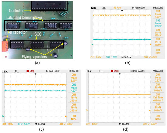
Figure 12.
Experimental results of SIMO DC-DC converter. (a) Prototype of SIMO DC-DC converter. (b) Forwarding voltage of . (c) Forwarding and regenerative voltage of 4. (d) Forwarding output voltage of 3.
6. Conclusions
The proposed speed transmission system provides speed control in E-vehicles (EVs) for higher acceleration and deceleration. The transmission control is also used to control regenerative braking, which uses slowdown or acceleration to feed energy back into the battery. In addition, simulation, modeling, and analysis are used to ensure that the proposed system delivers optimal efficiency and effective braking actions. The four-transmission speed control is designed using 14 switches and 4 capacitors. The efficiency of the proposed system is more than 90% when the bicycle load is considered, the speed is 13 RPM and the measured torque is 15 Nm. In addition, this proposed converter can be used both in fuel cell and battery systems. The main advantage of this system is that multiple speed transmission (1–3 times the input voltage) is possible by performing different charging operations of the capacitors with different switching patterns.
Author Contributions
Conceptualization, S.S., R.D. and V.S.; Investigation, S.S. and V.S.; Methodology, S.S. and V.S.; Resources, C.N.R. and S.A.; Software, C.N.R.; Supervision, V.S.; Validation, R.D. and J.R.K.; Visualization, R.D. and J.R.K.; Writing—original draft, V.S.; Writing—review & editing, S.S. and V.S. All authors have read and agreed to the published version of the manuscript.
Funding
This research was funded by NIL.
Data Availability Statement
Not applicable.
Conflicts of Interest
The authors declare no conflict of interest.
References
- How to Make Urban Mobility Clean. Green. 2018. Available online: http://www.internationaltransportforum.org (accessed on 30 June 2022).
- Mansour, A.; Faouzi, B.; Jamel, G.; Ismahen, E. Design and analysis of a high frequency DC–DC converters for fuel cell and super-capacitor used in electrical vehicle. Int. J. Hydrogen Energy 2014, 39, 1580–1592. [Google Scholar] [CrossRef]
- Tian, Y.; Zhang, N.; Zhou, S.; Walker, P.D. Model and gear shifting control of a novel two-speed transmission for battery electric vehicles. Mech. Mach. Theory 2020, 152, 103902. [Google Scholar] [CrossRef]
- Walker, P.; Zhu, B.; Zhang, N. Powertrain dynamics and control of a two speed dual clutch transmission for electric vehicles. Mech. Syst. Signal Process. 2017, 85, 1–15. [Google Scholar] [CrossRef]
- Fang, S.; Song, J.; Song, H.; Tai, Y.; Li, F.; Nguyen, T.S. Design and control of a novel two-speed uninterrupted mechanical transmission for electric vehicles. Mech. Syst. Signal Process. 2016, 75, 473–493. [Google Scholar] [CrossRef]
- Tian, Y.; Ruan, J.; Zhang, N.; Wu, J.; Walker, P. Modelling and control of a novel two-speed transmission for electric vehicles. Mech. Mach. Theory 2018, 127, 13–32. [Google Scholar] [CrossRef]
- Dal Bianco, N.; Lot, R.; Matthys, K. Lap time simulation and design optimisation of a brushed DC electric motorcycle for the Isle of Man TT Zero Challenge. Veh. Syst. Dyn. 2018, 56, 27–54. [Google Scholar] [CrossRef]
- Subburaj, V.; Zhaikhan, A.; Jena, D.; Perumal, P.; Mustafa, Y.; Ruderman, A. Investigation of a family of dual-output coupled/decoupled switched capacitor converter for low-power applications. IET Circuits Devices Syst. 2018, 13, 352–360. [Google Scholar] [CrossRef]
- Kumar, B.H.; Lokhande, M.M.; Karasani, R.R.; Borghate, V.B. Fault tolerant operation of chb multilevel inverters based on the svm technique using an auxiliary unit. J. Power Electron. 2018, 18, 56–69. [Google Scholar]
- Kumar, B.H.; Lokhande, M.M.; Reddy, K.R.; Borghate, V.B. An improved space vector pulse width modulation for nine-level asymmetric cascaded H-bridge three-phase inverter. Arab. J. Sci. Eng. 2019, 44, 2453–2465. [Google Scholar] [CrossRef]
- Zhang, J.; Lv, C.; Qiu, M.; Li, Y.; Sun, D. Braking energy regeneration control of a fuel cell hybrid electric bus. Energy Convers. Manag. 2013, 76, 1117–1124. [Google Scholar] [CrossRef]
- Gao, Y.; Chen, L.; Ehsani, M. Investigation of the effectiveness of regenerative braking for EV and HEV. SAE Trans. 1999, 3184–3190. [Google Scholar] [CrossRef]
- Zhang, J.; Lv, C.; Gou, J.; Kong, D. Cooperative control of regenerative braking and hydraulic braking of an electrified passenger car. Proc. Inst. Mech. Eng. Part D J. Automob. Eng. 2012, 226, 1289–1302. [Google Scholar] [CrossRef]
- Xu, C.D.; Cheng, K.W.E.; Ye, Y.M. A Topology of Step-Down Resonant Switched-Capacitor-Based AC–DC Converter for High-Frequency AC Distribution. J. Circuits Syst. Comput. 2015, 24, 1550154. [Google Scholar] [CrossRef]
- Kishore, G.I.; Tripathi, R.K. High Gain Single Switch DC-DC Converter Based on Switched Capacitor Cells. J. Circuits Syst. Comput. 2020, 29, 2050188. [Google Scholar] [CrossRef]
- Ben-Yaakov, S. On the influence of switch resistances on switched-capacitor converter losses. IEEE Trans. Ind. Electron. 2011, 59, 638–640. [Google Scholar] [CrossRef]
- Zhaikhan, A.; Subburaj, V.; Jena, D.; Perumal, P.; Ruderman, A. Design, modeling and analysis of a new dual input-output switched capacitor converter. In Proceedings of the TENCON 2017—2017 IEEE Region 10 Conference, Penang, Malaysia, 5–8 November 2017; pp. 673–677. [Google Scholar]
- Aden, I.; Kahveci, H.; Şahin, M.E. Single Input, Multiple Output DC-DC Buck Converter for Electric Vehicles. Turk. J. Electromech. Energy 2017, 2, 7–13. [Google Scholar]
- Ahmad, F.; Haider, A.A.; Naveed, H.; Mustafa, A.; Ahmad, I. Multiple Input Multiple Output DC to DC Converter. In Proceedings of the 2018 5th International Multi-Topic ICT Conference (IMTIC), Jamshoro, Pakistan, 25–27 April 2018; pp. 1–6. [Google Scholar]
- Castle, O.D.; El Shahat, A. Single-input-multi-output (SIMO) converter for nano-grids applications. In Proceedings of the SoutheastCon 2017, Concord, NC, USA, 30 March–2 April 2017; pp. 1–5. [Google Scholar]
Publisher’s Note: MDPI stays neutral with regard to jurisdictional claims in published maps and institutional affiliations. |
© 2022 by the authors. Licensee MDPI, Basel, Switzerland. This article is an open access article distributed under the terms and conditions of the Creative Commons Attribution (CC BY) license (https://creativecommons.org/licenses/by/4.0/).