
Non-Isolated Multiport Converter for Renewable Energy Sources: A Comprehensive Review


Abstract
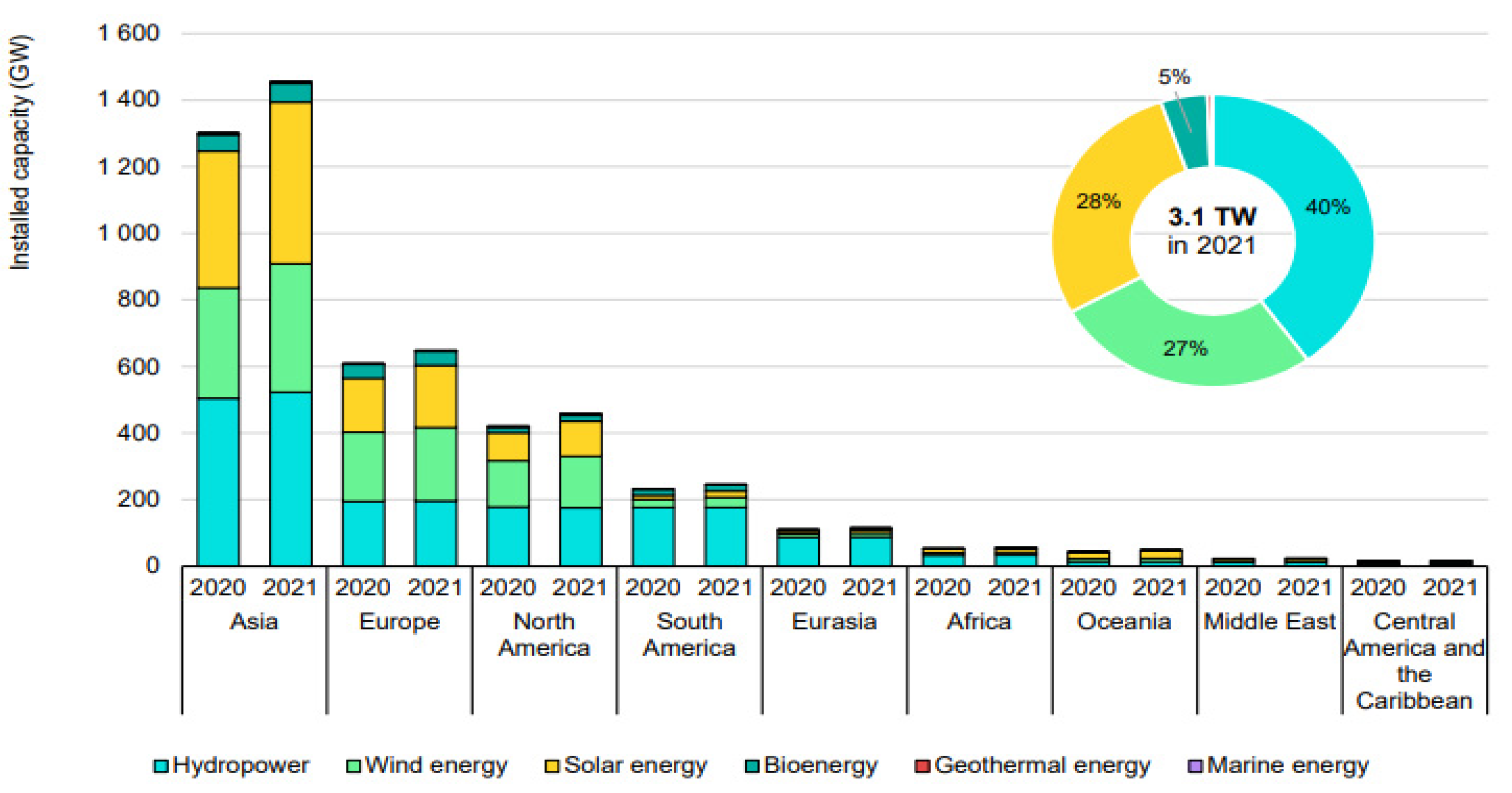
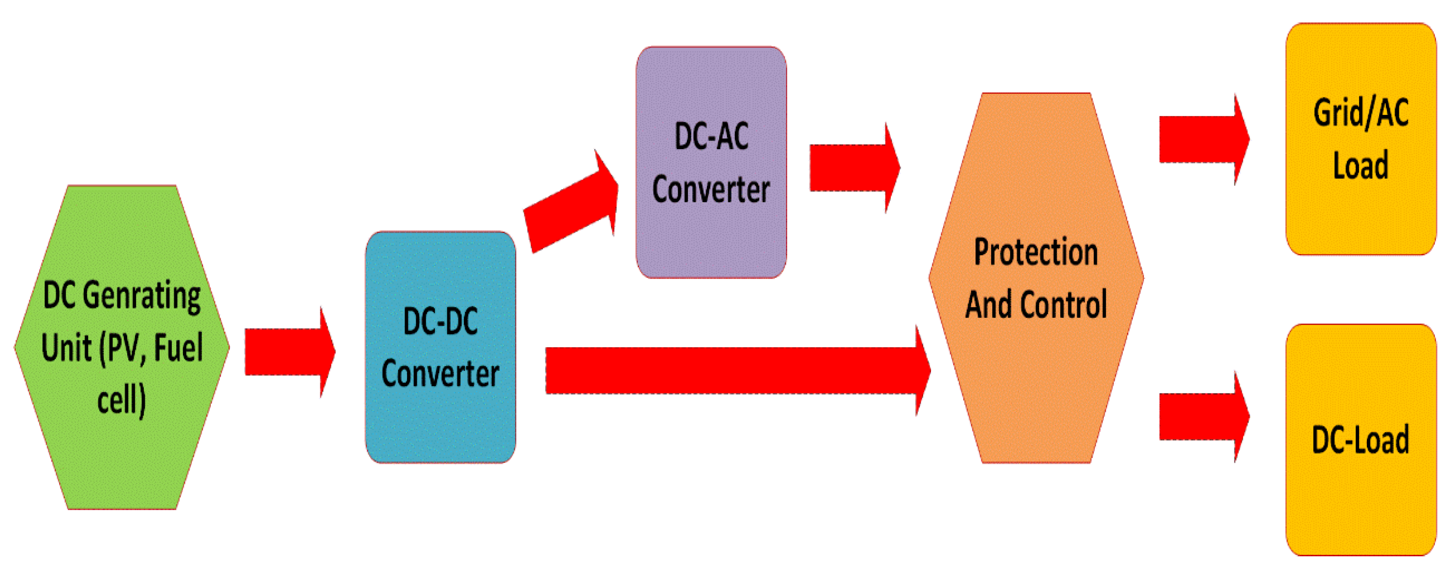
:1. Introduction
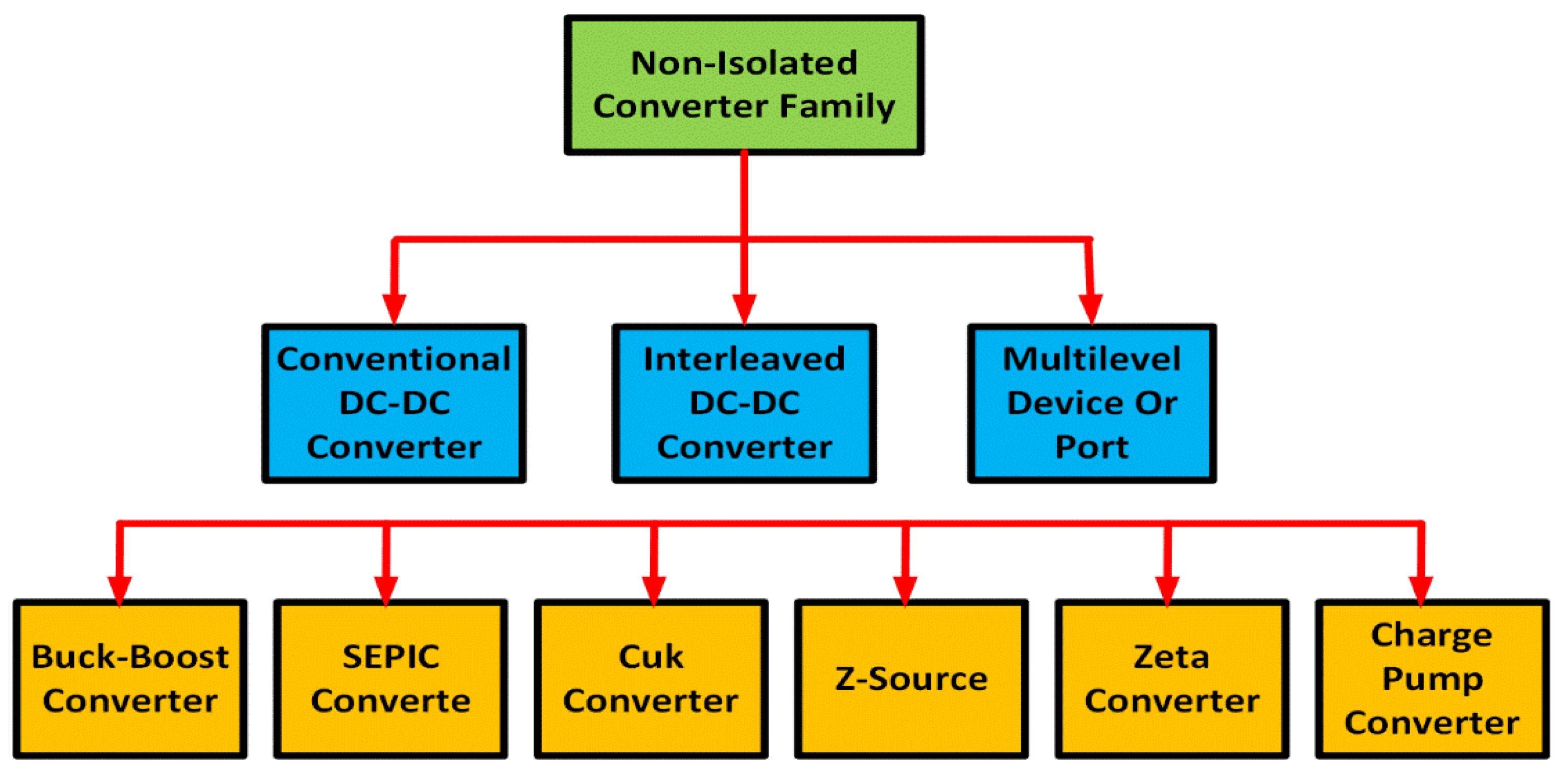
2. Classification of NI DC-DC Converter for RES
Non-Isolated Converter Family
- (a)
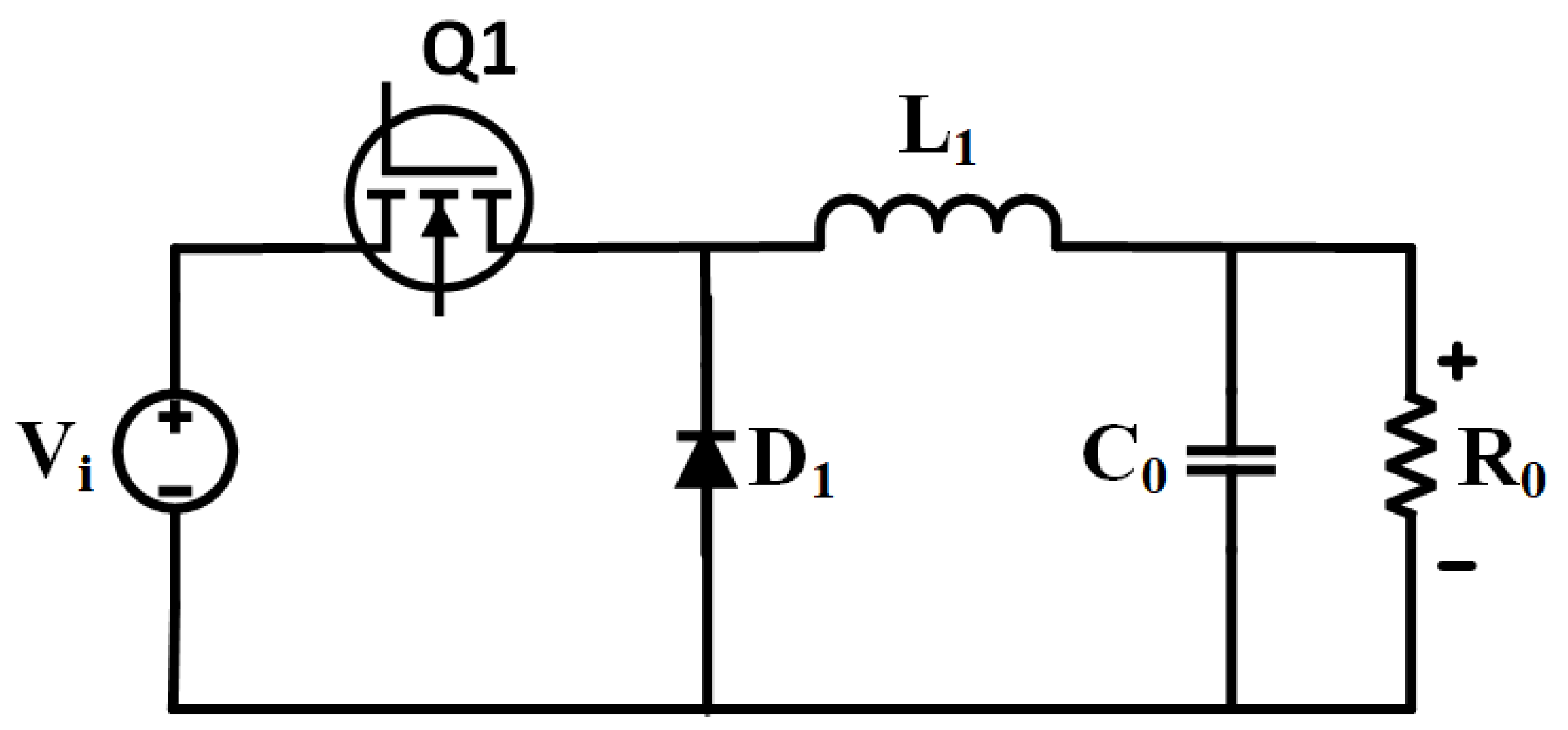
- Boost Converters
- (b)
- Buck DC-DC Converters
- (c)
- Buck–boost Converters
- (d)
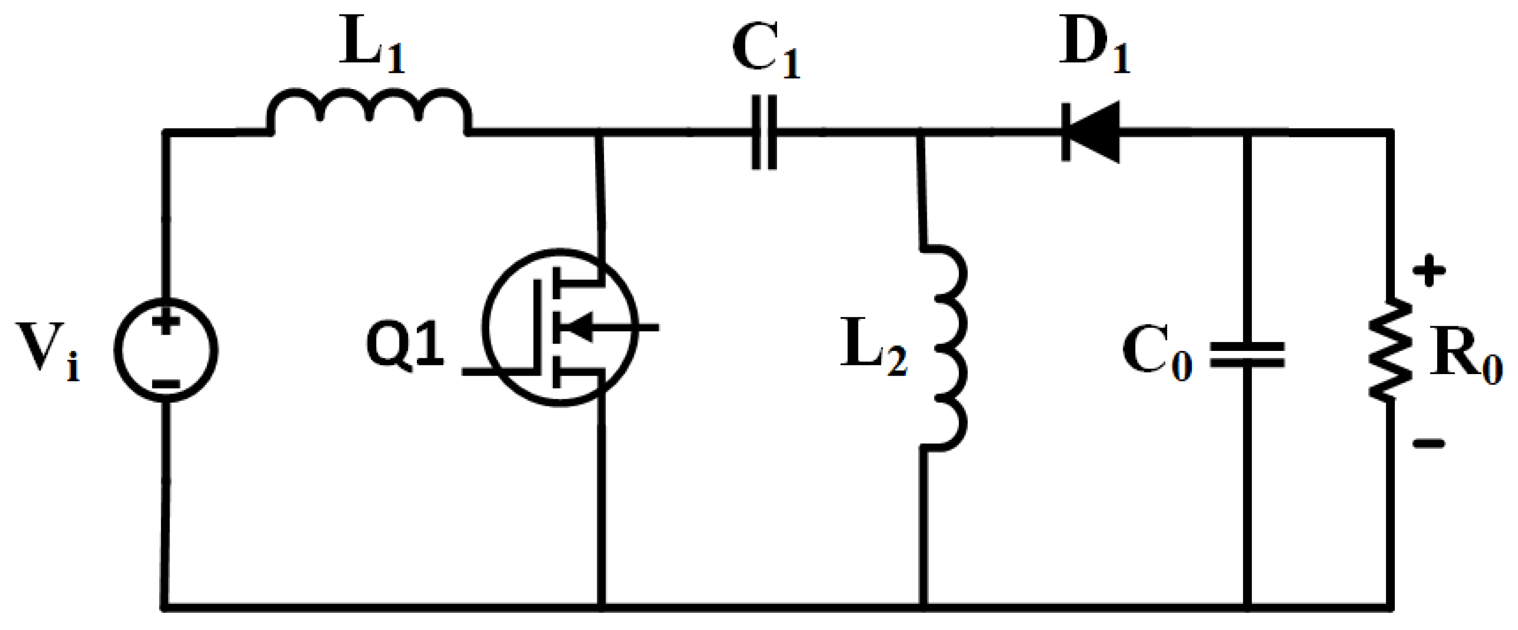
- DC-DC Cuk Converter
- (e)
- SEPIC DC-DC Converter
- (f)
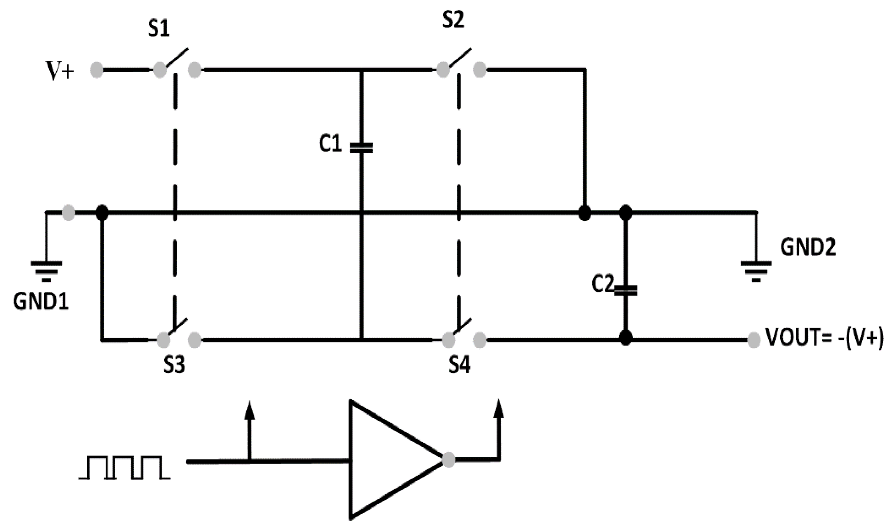
- Charge pump converter
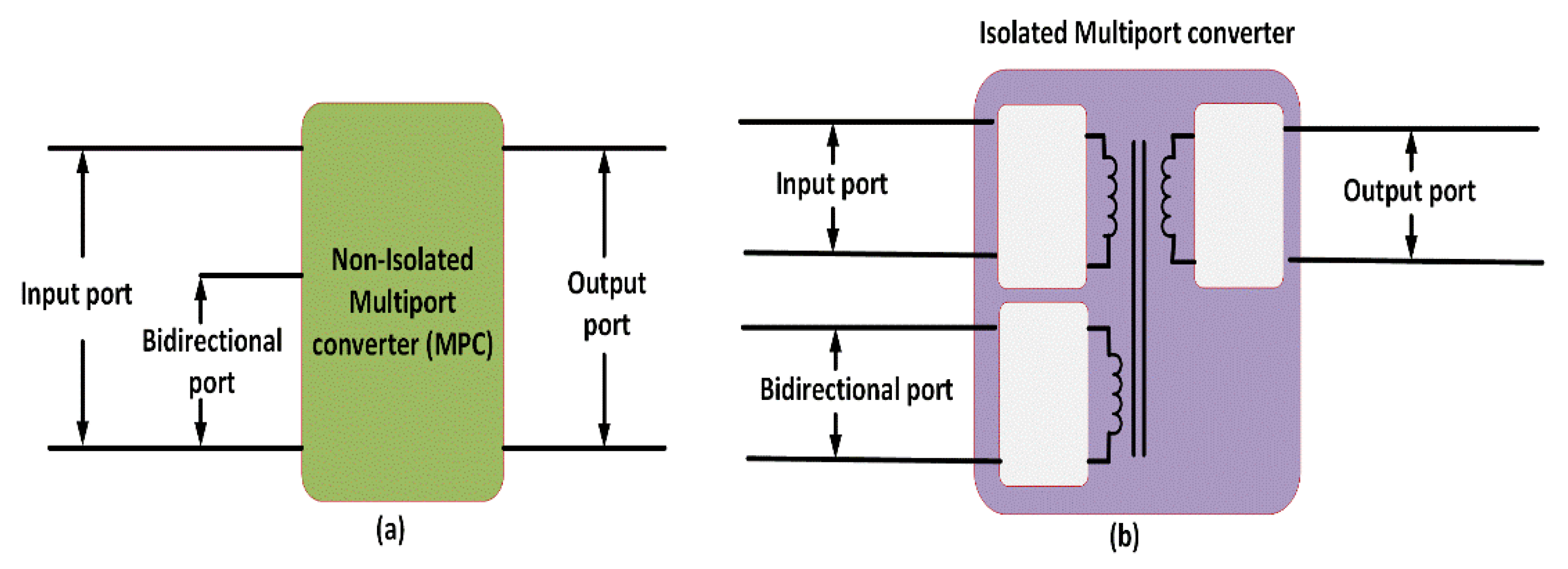
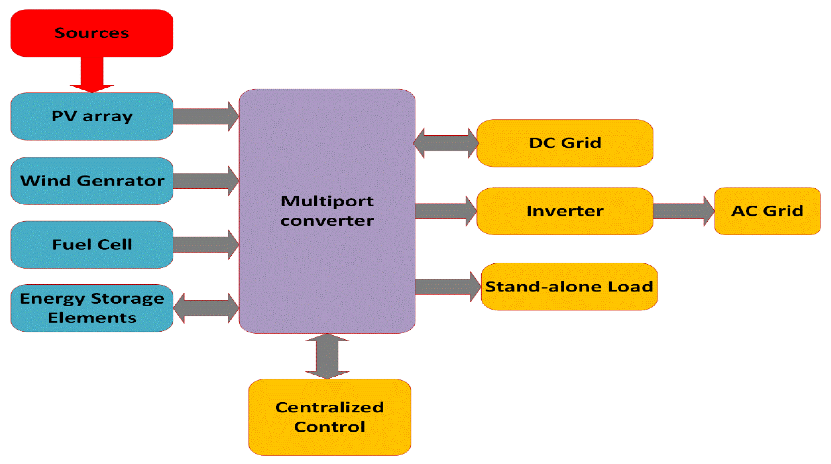
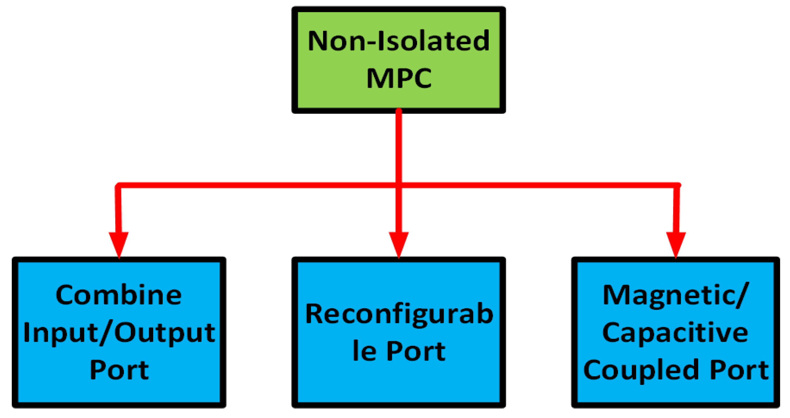
3. Multiport Non-Isolated Converter
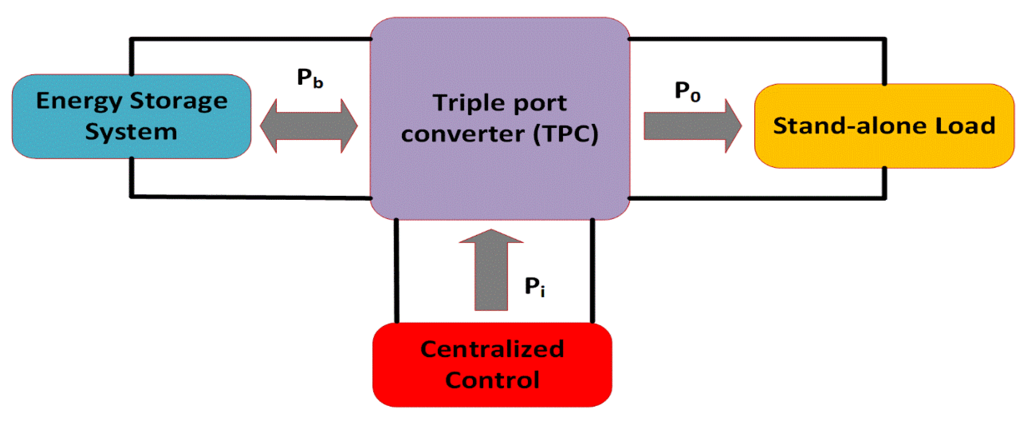
4. Generalized Operating Mode of MPC
4.1. DISO DC-DC Converter
4.2. DC-DC Converter in Single Input–Dual Output Configuration (SIDO)
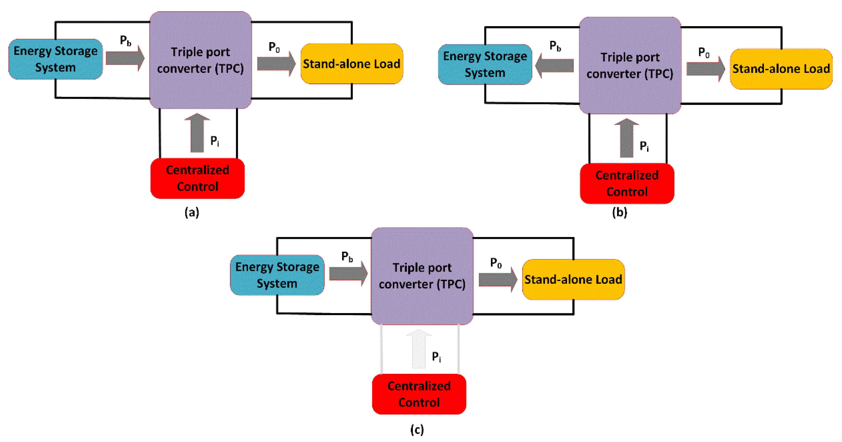
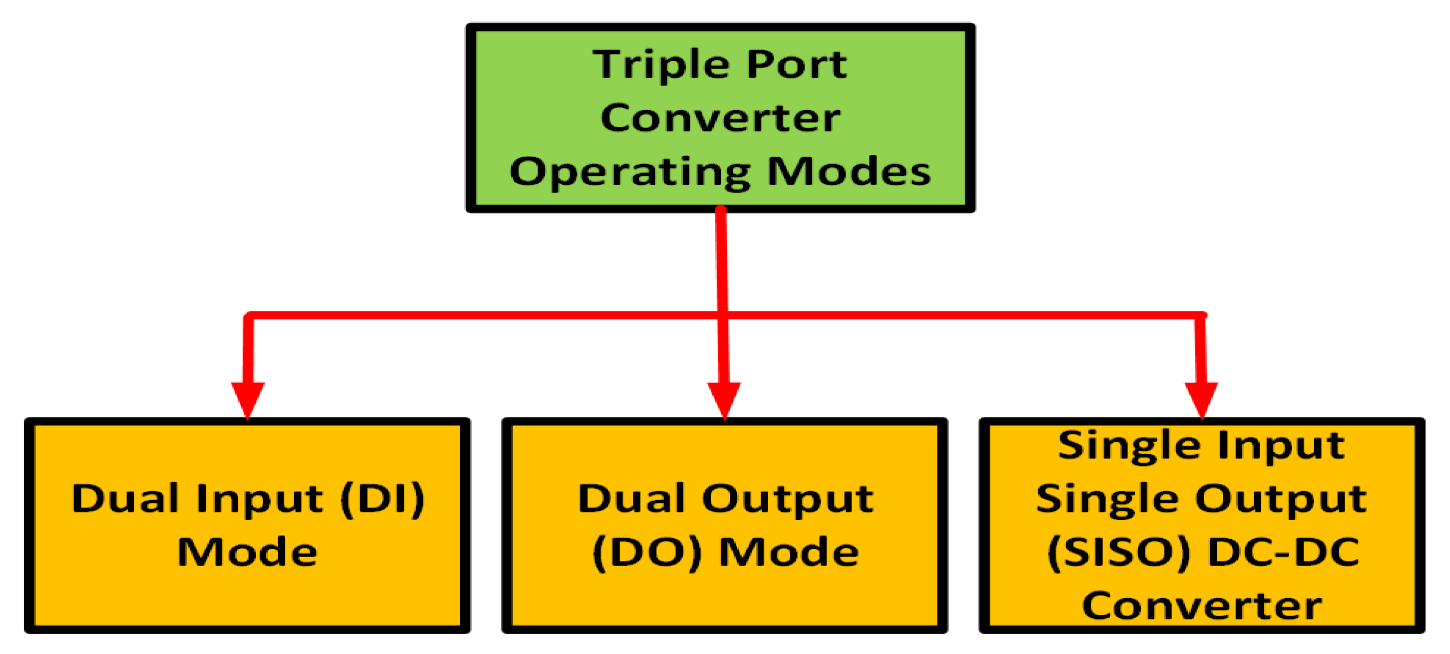
4.3. Multi Input–Multi Output Converters (MIMO)
- (a)
- Dual input (DI) mode
- (b)
- Dual output (DO) mode
- (c)
- Single input–single output (SISO) mode
5. Topologies Comparison in Multi-Input Non-Isolated DC-DC Converter
6. Conclusions
Author Contributions
Funding
Data Availability Statement
Acknowledgments
Conflicts of Interest
Nomenclature
| MPC | DC-DC multiport converter |
| DISO | Dual input single output |
| GM | Gain margin |
| HEV | Hybrid electric vehicle |
| HES | Hybrid energy storage |
| ICAD | Individual channel analysis and design |
| MPPT | Maximum power point tracking |
| MIMO | Multi-input single output |
| NI | Non-isolated |
| PM | Phase margin |
| PI | Proportional Integral |
| PWM | Pulse width modulation |
| RE | Renewable energy |
| RES | Renewable energy sources |
| SISO | Single input single output |
| SEPIC | Single-Ended Primary Inductor Converter |
| SPC | Single-port converters |
| SDGs | Sustainable Development Goals |
| SMP | Switched Mode Power |
| HTF | The harmonic transfer function |
| TPC | Two-port converter |
| UPS | Uninterrupted power supplies |
| VSC | Voltage source converter |
| ZVS | Zero voltage switching |
References
- Elavarasan, R.M.; Shafiullah, G.M.; Padmanaban, S.; Kumar, N.M.; Annam, A.; Vetrichelvan, A.M.; Mihet-Popa, L.; Holm-Nielsen, J.B. A Comprehensive Review on Renewable Energy Development, Challenges, and Policies of Leading Indian States With an International Perspective. IEEE Access 2020, 8, 74432–74457. [Google Scholar] [CrossRef]
- Gomathy, S.; Senthilnathan, D.N.; Swathi, S.; Poorviga, R.; Dinakaran, P. Review On Multi Input Multi Output DC-DC Converter. Int. J. Sci. Technol. Res. 2020, 9, 428–440. [Google Scholar]
- Karimi-Davijani, H.; Ojo, O. Controllability Analysis of Renewable Energy Systems. Power Electron. Renew. Energy Syst. Transp. Ind. Appl. 2014, 199–230. [Google Scholar] [CrossRef]
- Kumar, A.R.; Ramakrishnan, M. A scoping review on recent advancements in domestic applications of solar thermal systems. J. Therm. Eng. 2022, 8, 426–444. [Google Scholar] [CrossRef]
- Ramkumar, A.; Ramakrishnan, M. A comprehensive review on small-scale thermal energy harvesters: Advancements and applications. Mater. Today Proc. 2022, 66, 1552–1562. [Google Scholar] [CrossRef]
- Gielen, D.; Boshell, F.; Saygin, D.; Bazilian, M.D.; Wagner, N.; Gorini, R. The role of renewable energy in the global energy transformation. Energy Strategy Rev. 2019, 24, 38–50. [Google Scholar] [CrossRef]
- Tang, Z.; Yang, Y.; Blaabjerg, F. An Interlinking Converter for Renewable Energy Integration Into Hybrid Grids. IEEE Trans. Power Electron. 2021, 36, 2499–2504. [Google Scholar] [CrossRef]
- Babu, T.S.; Vasudevan, K.R.; Ramachandaramurthy, V.K.; Sani, S.B.; Chemud, S.; Lajim, R.M. A Comprehensive Review of Hybrid Energy Storage Systems: Converter Topologies, Control Strategies and Future Prospects. IEEE Access 2020, 8, 148702–148721. [Google Scholar] [CrossRef]
- Raheja, L. Power Electronics for Renewable Energy Systems: Current Approaches and Future Prospects. Int. J. Sci. Eng. Manag. 2019, 4, 3–7. [Google Scholar]
- Choy, W.J.; Costabeber, A.; Buticchi, G.; Trentin, A.; Walker, A.; Galea, M.; Paciura, K.; O’Brien, J.; Palmer, B. A Multiport Power Electronics Converter for Hybrid Traction Applications. IEEE Access 2021, 9, 99181–99192. [Google Scholar] [CrossRef]
- Marchesoni, M.; Vacca, C. New DC–DC Converter for Energy Storage System Interfacing in Fuel Cell Hybrid Electric Vehicles. IEEE Trans. Power Electron. 2007, 22, 301–308. [Google Scholar] [CrossRef]
- Amirabadi, M.; Toliyat, H.A.; Alexander, W.C. A Multiport AC Link PV Inverter With Reduced Size and Weight for Stand-Alone Application. IEEE Trans. Ind. Appl. 2013, 49, 2217–2228. [Google Scholar] [CrossRef]
- Jalbrzykowski, S.; Citko, T. A bidirectional DC-DC converter for renewable energy systems. Bull. Pol. Acad. Sci. Tech. Sci. 2009, 57, 363–368. [Google Scholar] [CrossRef]
- Moradpour, R.; Ardi, H.; Tavakoli, A. Design and Implementation of a New SEPIC-Based High Step-Up DC/DC Converter for Renewable Energy Applications. IEEE Trans. Ind. Electron. 2017, 65, 1290–1297. [Google Scholar] [CrossRef]
- Fang, X.; Ding, X.; Zhong, S.; Tian, Y. Improved Quasi-Y-Source DC-DC Converter for Renewable Energy. CPSS Trans. Power Electron. Appl. 2019, 4, 163–170. [Google Scholar] [CrossRef]
- Bhaskar, M.S.; Almakhles, D.J.; Padmanaban, S.; Blaabjerg, F.; Subramaniam, U.; Ionel, D.M. Analysis and Investigation of Hybrid DC–DC Non-Isolated and Non-Inverting Nx Interleaved Multilevel Boost Converter (Nx-IMBC) for High Voltage Step-Up Applications: Hardware Implementation. IEEE Access 2020, 8, 87309–87328. [Google Scholar] [CrossRef]
- Liu, H.; Hu, H.; Wu, H.; Xing, Y.; Batarseh, I. Overview of High-Step-Up Coupled-Inductor Boost Converters. IEEE J. Emerg. Sel. Top. Power Electron. 2016, 4, 689–704. [Google Scholar] [CrossRef]
- Esteki, M.; Poorali, B.; Adib, E.; Farzanehfard, H. Interleaved Buck Converter With Continuous Input Current, Extremely Low Output Current Ripple, Low Switching Losses, and Improved Step-Down Conversion Ratio. IEEE Trans. Ind. Electron. 2015, 62, 4769–4776. [Google Scholar] [CrossRef]
- Sidorov, V.; Chub, A.; Vinnikov, D.; Bakeer, A. An Overview and Comprehensive Comparative Evaluation of Constant-Frequency Voltage Buck Control Methods for Series Resonant DC–DC Converters. IEEE Open J. Ind. Electron. Soc. 2020, 2, 65–79. [Google Scholar] [CrossRef]
- Lee, H.-S.; Yun, J.-J. High-Efficiency Bidirectional Buck–Boost Converter for Photovoltaic and Energy Storage Systems in a Smart Grid. IEEE Trans. Power Electron. 2019, 34, 4316–4328. [Google Scholar] [CrossRef]
- Sarikhani, A.; Allahverdinejad, B.; Hamzeh, M. A Nonisolated Buck–Boost DC–DC Converter With Continuous Input Current for Photovoltaic Applications. IEEE J. Emerg. Sel. Top. Power Electron. 2021, 9, 804–811. [Google Scholar] [CrossRef]
- Onar, O.C.; Kobayashi, J.; Erb, D.C.; Khaligh, A. A Bidirectional High-Power-Quality Grid Interface With a Novel Bidirectional Noninverted Buck–Boost Converter for PHEVs. IEEE Trans. Veh. Technol. 2012, 61, 2018–2032. [Google Scholar] [CrossRef]
- Wu, H.; Zhang, J.; Xing, Y. A Family of Multiport Buck–Boost Converters Based on DC-Link-Inductors (DLIs). IEEE Trans. Power Electron. 2015, 30, 735–746. [Google Scholar] [CrossRef]
- Khodabandeh, M.; Afshari, E.; Amirabadi, M. A Family of Ćuk, Zeta, and SEPIC Based Soft-Switching DC–DC Converters. IEEE Trans. Power Electron. 2019, 34, 9503–9519. [Google Scholar] [CrossRef]
- Pandey, R.; Singh, B. A Power-Factor-Corrected LLC Resonant Converter for Electric Vehicle Charger Using Cuk Converter. IEEE Trans. Ind. Appl. 2019, 55, 6278–6286. [Google Scholar] [CrossRef]
- Ferrera, M.B.; Litran, S.P.; Aranda, E.D.; Marquez, J.M.A. A Converter for Bipolar DC Link Based on SEPIC-Cuk Combination. IEEE Trans. Power Electron. 2015, 30, 6483–6487. [Google Scholar] [CrossRef]
- Ardi, H.; Ajami, A. Study on a High Voltage Gain SEPIC-Based DC–DC Converter With Continuous Input Current for Sustainable Energy Applications. IEEE Trans. Power Electron. 2018, 33, 10403–10409. [Google Scholar] [CrossRef]
- Maroti, P.K.; Padmanaban, S.; Holm-Nielsen, J.B.; Bhaskar, M.S.; Meraj, M.; Iqbal, A. A New Structure of High Voltage Gain SEPIC Converter for Renewable Energy Applications. IEEE Access 2019, 7, 89857–89868. [Google Scholar] [CrossRef]
- Karimian, F.; Nahavandi, A. Design and analysis of a new structure of non-isolated DC–DC cuk–boost converter with high voltage gain. IET Power Electron. 2019, 12, 530–540. [Google Scholar] [CrossRef]
- Suresh, K.; Bharatiraja, C.; Chellammal, N.; Tariq, M.; Chakrabortty, R.K.; Ryan, M.J.; Alamri, B. A Multifunctional Non-Isolated Dual Input-Dual Output Converter for Electric Vehicle Applications. IEEE Access 2021, 9, 64445–64460. [Google Scholar] [CrossRef]
- Zhou, Z.; Wu, H.; Ma, X.; Xing, Y. A non-isolated three-port converter for stand-alone renewable power system. In Proceedings of the IECON Proceedings (Industrial Electronics Conference), Montreal, QC, Canada, 25–28 October 2012; pp. 3352–3357. [Google Scholar] [CrossRef]
- Zhu, H.; Zhang, D.; Zhang, B.; Zhou, Z. A Nonisolated Three-Port DC–DC Converter and Three-Domain Control Method for PV-Battery Power Systems. IEEE Trans. Ind. Electron. 2015, 62, 4937–4947. [Google Scholar] [CrossRef]
- Anuradha, C.; Sakthivel, C.; Venkatesan, T.; Chellammal, N. Analysis of Non-Isolated Multi-Port Single Ended Primary Inductor Converter or Standalone Applications. Energies 2018, 11, 539. [Google Scholar] [CrossRef]
- Sivasankar, N.; Devabalaji, K.R. Comparative Analysis of Non-Isolated Three port converters for Solar and Energy Storage Integration. Int. J. Eng. Trends Technol. 2020, 68, 73–77. [Google Scholar]
- Cheng, T.; Lu, D.D.-C.; Qin, L. Non-Isolated Single-Inductor DC/DC Converter With Fully Reconfigurable Structure for Renewable Energy Applications. IEEE Trans. Circuits Syst. II Express Briefs 2018, 65, 351–355. [Google Scholar] [CrossRef]
- Khasim, S.R.; Dhanamjayulu, C.; Muyeen, S.M. A Single Inductor Multi-Port Power Converter for Electric Vehicle Applications. IEEE Access 2023, 11, 3367–3385. [Google Scholar] [CrossRef]
- Shayeghi, H.; Pourjafar, S.; Lopez, J.A. A Bidirectional Multi-Port Structure of DC-DC Converter for Energy Storage Systems. J. Energy Manag. Technol. 2023, 7, 69–79. [Google Scholar]
- Suvvala, J.; Kumar, K.S. Implementation of EFC Charging Station by Multiport Converter with Integration of RES. Energies 2023, 16, 1521. [Google Scholar] [CrossRef]
- Gevorkov, L.; Domínguez-García, J.L.; Martínez, À.F. Modern Trends in MultiPort Converters: Isolated, Non-Isolated, and Partially Isolated. In Proceedings of the 2022 IEEE 63th International Scientific Conference on Power and Electrical Engineering of Riga Technical University (RTUCON), Riga, Latvia, 10–12 October 2022; pp. 1–6. [Google Scholar]
- Rezaii, R.; Ghosh, S.; Safayatullah, M.; Tayebi, S.M.; Batarseh, I. Quad-Input Single-Resonant Tank LLC Converter for PV Applications. IEEE Trans. Ind. Appl. 2023, 1–19. [Google Scholar] [CrossRef]
- Veerachary, M.; Yadav, N. Design and Analysis of Two-input Single-output DC-DC Converter. In Proceedings of the 2021 IEEE 4th International Conference on Computing, Power and Communication Technologies, GUCON 2021, Kuala Lumpur, Malaysia, 24–26 September 2021; pp. 1–6. [Google Scholar] [CrossRef]
- Tian, Q.; Zhou, G.; Liu, R.; Zhang, X.; Leng, M. Topology Synthesis of a Family of Integrated Three-Port Converters for Renewable Energy System Applications. IEEE Trans. Ind. Electron. 2021, 68, 5833–5846. [Google Scholar] [CrossRef]
- Al-Soeidat, M.R.; Aljarajreh, H.; Khawaldeh, H.A.; Lu, D.D.-C.; Zhu, J. A Reconfigurable Three-Port DC–DC Converter for Integrated PV-Battery System. IEEE J. Emerg. Sel. Top. Power Electron. 2020, 8, 3423–3433. [Google Scholar] [CrossRef]
- Zhao, J.; Iu, H.H.; Fernando, T.; An, L.; Lu, D.D.-C. Design of a non-isolated single-switch three-port DC-DC converter for standalone PV-battery power system. In Proceedings of the IEEE International Symposium on Circuits and Systems, Lisbon, Portugal, 24–27 May 2015; Volume 2015, pp. 2493–2496. [Google Scholar] [CrossRef]
- Chen, G.; Jin, Z.; Deng, Y.; He, X.; Qing, X. Principle and Topology Synthesis of Integrated Single-Input Dual-Output and Dual-Input Single-Output DC–DC Converters. IEEE Trans. Ind. Electron. 2018, 65, 3815–3825. [Google Scholar] [CrossRef]
- Dhananjaya, M.; Jagabar Sathik, M.; Padmanaban, S.; Almakhles, D.; Potnuru, D. A New Configuration of Switch and Source Fault-Tolerant Dual-Input Single-Output DC-DC Converter. In Proceedings of the 2021 IEEE 4th International Conference on Computing, Power and Communication Technologies, GUCON 2021, Kuala Lumpur, Malaysia, 24–26 September 2021; pp. 1–6. [Google Scholar] [CrossRef]
- Danyali, S.; Moradkhani, A.; Aazami, R.; Haghi, M. New Dual-Input Zero-Voltage Switching DC–DC Boost Converter for Low-Power Clean Energy Applications. IEEE Trans. Power Electron. 2021, 36, 11532–11542. [Google Scholar] [CrossRef]
- Prabhala, V.A.K.; Fajri, P.; Gouribhatla, V.S.P.; Baddipadiga, B.P.; Ferdowsi, M. A DC–DC Converter With High Voltage Gain and Two Input Boost Stages. IEEE Trans. Power Electron. 2016, 31, 4206–4215. [Google Scholar] [CrossRef]
- Kumar, L.; Jain, S. A multiple source DC/DC converter topology. Int. J. Electr. Power Energy Syst. 2013, 51, 278–291. [Google Scholar] [CrossRef]
- Li, Y.; Ruan, X.; Yang, D.; Liu, F.; Tse, C.K. Synthesis of Multiple-Input DC/DC Converters. IEEE Trans. Power Electron. 2010, 25, 2372–2385. [Google Scholar] [CrossRef]
- Zhang, N.; Sutanto, D.; Muttaqi, K.M. A review of topologies of three-port DC–DC converters for the integration of renewable energy and energy storage system. Renew. Sustain. Energy Rev. 2016, 56, 388–401. [Google Scholar] [CrossRef]
- Mishra, S.K.; Nayak, K.K.; Rana, M.S.; Dharmarajan, V. Switched-boost action based multiport converter. IEEE Trans. Ind. Appl. 2018, 55, 964–975. [Google Scholar] [CrossRef]
- Rehman, Z.; Al-Bahadly, I.; Mukhopadhyay, S. Multiinput DC–DC converters in renewable energy applications—An overview. Renew. Sustain. Energy Rev. 2015, 41, 521–539. [Google Scholar] [CrossRef]
- Behera, D.K.; Anand, I.; Reddy, B.M.; Senthilkumar, S. A Robust Power Control Scheme for a Dual-Input Single-Output converter with a Standalone Solar PV System. In Proceedings of the 2018 IEEE International Conference on Power Electronics, Drives and Energy Systems, PEDES 2018, Chennai, India, 18–21 December 2018; pp. 1–6. [Google Scholar] [CrossRef]
- Liu, X.; Xu, J.; Chen, Z.; Wang, N. Single-Inductor Dual-Output Buck–Boost Power Factor Correction Converter. IEEE Trans. Ind. Electron. 2015, 62, 943–952. [Google Scholar] [CrossRef]
- Yang, H.-A.; Yang, W.-H.; Chen, K.-H.; Wey, C.-L.; Lin, Y.-H.; Lee, C.-C.; Lin, J.-R.; Tsai, T.-Y.; Lai, S.-C. 12.7 A 96%-efficiency and 0.5%-current-cross-regulation single-inductor multiple floating-output LED driver with 24b color resolution. In Proceedings of the Digest of Technical Papers—IEEE International Solid-State Circuits Conference, Cambridge, MA, USA, 3 February 2016; Volume 59, pp. 230–231. [Google Scholar] [CrossRef]
- Liu, Y.; Chen, G.; Hu, Y.; Huang, L.; Qing, X. Magnetic Coupling Branch Based Dual-Input/Output DC–DC Converters With Improved Cross-Regulation and Soft-Switching Operation. IEEE Trans. Ind. Electron. 2020, 67, 7167–7178. [Google Scholar] [CrossRef]
- Ye, Y.; Cheng, K.W.E. Single-switch single-inductor multi-output pulse width modulation converters based on optimised switched-capacitor. IET Power Electron. 2015, 8, 2168–2175. [Google Scholar] [CrossRef]
- Ray, O.; Josyula, A.P.; Mishra, S.; Joshi, A. Integrated Dual-Output Converter. IEEE Trans. Ind. Electron. 2015, 62, 371–382. [Google Scholar] [CrossRef]
- Hajari, S.; Ray, O. Operation and Control of Integrated Dual-Output Converter interfacing non-linear loads. In Proceedings of the 9th IEEE International Conference on Power Electronics, Drives and Energy Systems, PEDES 2020, Jaipur, India, 16–19 December 2020; pp. 1–6. [Google Scholar] [CrossRef]
- Dam, S.; Mandal, P. A Hybrid, Fully-Integrated, Dual-Output DC–DC Converter for Portable Electronics. IEEE Trans. Power Electron. 2021, 36, 4360–4370. [Google Scholar] [CrossRef]
- Goh, T.Y.; Ng, W.T. Single Discharge Control for Single-Inductor Multiple-Output DC–DC Buck Converters. IEEE Trans. Power Electron. 2018, 33, 2307–2316. [Google Scholar] [CrossRef]
- dos Santos, E.C. Dual-output dc–dc buck converters with bidirectional and unidirectional characteristics. IET Power Electron. 2013, 6, 999–1009. [Google Scholar] [CrossRef]
- Song, S.; Chen, G.; Liu, Y.; Hu, Y.; Ni, K.; Wang, Y. A Three-Switch-Based Single-Input Dual-Output Converter With Simultaneous Boost & Buck Voltage Conversion. IEEE Trans. Ind. Informatics 2020, 16, 4468–4477. [Google Scholar] [CrossRef]
- Nahavandi, A.; Hagh, M.T.; Sharifian, M.B.B.; Danyali, S. A Nonisolated Multiinput Multioutput DC–DC Boost Converter for Electric Vehicle Applications. IEEE Trans. Power Electron. 2015, 30, 1818–1835. [Google Scholar] [CrossRef]
- Mohseni, P.; Hosseini, S.H.; Sabahi, M.; Jalilzadeh, T.; Maalandish, M. A New High Step-Up Multi-Input Multi-Output DC–DC Converter. IEEE Trans. Ind. Electron. 2019, 66, 5197–5208. [Google Scholar] [CrossRef]
- Shan, Z.; Ding, X.; Jatskevich, J.; Tse, C.K. Synthesis of Multi-Input Multi-Output DC/DC Converters Without Energy Buffer Stages. IEEE Trans. Circuits Syst. II Express Briefs 2021, 68, 712–716. [Google Scholar] [CrossRef]
- Ahrabi, R.R.; Ardi, H.; Elmi, M.; Ajami, A. A Novel Step-Up Multiinput DC–DC Converter for Hybrid Electric Vehicles Application. IEEE Trans. Power Electron. 2017, 32, 3549–3561. [Google Scholar] [CrossRef]
- Kim, T.; Kwak, S. Single pole switch leg based multi-port converter with an energy storage. IET Power Electron. 2016, 9, 1322–1330. [Google Scholar] [CrossRef]
- Chen, G.; Liu, Y.; Qing, X.; Wang, F. Synthesis of Integrated Multiport DC–DC Converters With Reduced Switches. IEEE Trans. Ind. Electron. 2020, 67, 4536–4546. [Google Scholar] [CrossRef]
- Chandrasekar, B.; Nallaperumal, C.; Padmanaban, S.; Bhaskar, M.S.; Holm-Nielsen, J.B.; Leonowicz, Z.; Masebinu, S.O. Non-Isolated High-Gain Triple Port DC–DC Buck-Boost Converter With Positive Output Voltage for Photovoltaic Applications. IEEE Access 2020, 8, 113649–113666. [Google Scholar] [CrossRef]
- Nejabatkhah, F.; Danyali, S.; Hosseini, S.H.; Sabahi, M.; Niapour, S.M. Modeling and Control of a New Three-Input DC–DC Boost Converter for Hybrid PV/FC/Battery Power System. IEEE Trans. Power Electron. 2012, 27, 2309–2324. [Google Scholar] [CrossRef]
- Ding, S.; Wu, H.; Xing, Y.; Fang, Y.; Ma, X. Topology and control of a family of non-isolated three-port DC-DC converters with a bidirectional cell. In Proceedings of the Conference Proceedings—EEE Applied Power Electronics Conference and Exposition—APEC, Long Beach, CA, USA, 17–21 March 2013; pp. 1089–1094. [Google Scholar] [CrossRef]
- Wu, H.; Xing, Y.; Xia, Y.; Sun, K. A family of non-isolated three-port converters for stand-alone renewable power system. In Proceedings of the IECON Proceedings (Industrial Electronics Conference), Melbourne, Australia, 7–10 November 2011; pp. 1030–1035. [Google Scholar] [CrossRef]
- RamKumar, A.; Marimuthu, R. Energy, exergy, economic, environmental (4E) and frequency distribution analysis of train wind gust with real-time data for energy harvesting. Environ. Res. Commun. 2022, 12, 125002. [Google Scholar] [CrossRef]
- Gavris, M.; Muntean, N.; Cornea, O. A new dual-input hybrid buck DC-DC converter. In Proceedings of the International Aegean Conference on Electrical Machines and Power Electronics, ACEMP 2011 and Electromotion 2011 Joint Conference, Istanbul, Turkey, 8–10 September 2011; pp. 109–114. [Google Scholar] [CrossRef]
- Cai, J.; Zhong, Q.-C. Compact bidirectional DC-DC converters with two input sources. In Proceedings of the 2014 IEEE 5th International Symposium on Power Electronics for Distributed Generation Systems, PEDG 2014, Galway, Ireland, 24–27 June 2014; pp. 1–5. [Google Scholar] [CrossRef]
- Chen, Y.-M.; Liu, Y.-C.; Lin, S.-H. Double-Input PWM DC/DC Converter for High-/Low-Voltage Sources. IEEE Trans. Ind. Electron. 2006, 53, 1538–1545. [Google Scholar] [CrossRef]
- Marjani, J.; Imani, A.; Afjei, E.; Hekmati, A. A new dual output DC-DC converter with enhancing output voltage level. In Proceedings of the 2016 24th Iranian Conference on Electrical Engineering, ICEE 2016, Shiraz, Iran, 10–12 May 2016; pp. 573–577. [Google Scholar] [CrossRef]
- Kumar, P.; Rojas-Gonzalez, M. Novel 3-Switch Dual Output Buck Voltage Regulator. In Proceedings of the Conference Proceedings—IEEE Applied Power Electronics Conference and Exposition—APEC, Dallas, TX, USA, 19–23 March 2006; Volume 2006, pp. 467–473. [Google Scholar] [CrossRef]
- Hwu, K.I.; Yau, Y.T.; Shieh, J.-J. Dual-output boost converter. In Proceedings of the International Conference on Power Electronics and Drive Systems, Singapore, 5–8 December 2011; pp. 940–943. [Google Scholar] [CrossRef]
- Zhang, H.; Wang, X.; Harnefors, L.; Gong, H.; Hasler, J.-P.; Nee, H.-P. SISO Transfer Functions for Stability Analysis of Grid-Connected Voltage-Source Converters. IEEE Trans. Ind. Appl. 2019, 55, 2931–2941. [Google Scholar] [CrossRef]
- Guo, C.; Yang, S.; Liu, W.; Zhao, C. Single-Input–Single-Output Feedback Control Model and Stability Margin Analysis for Hybrid Dual-Infeed HVDC System. IEEE J. Emerg. Sel. Top. Power Electron. 2021, 9, 3061–3071. [Google Scholar] [CrossRef]
- Zhang, C.; Cai, X.; Rygg, A.; Molinas, M. Sequence Domain SISO Equivalent Models of a Grid-Tied Voltage Source Converter System for Small-Signal Stability Analysis. IEEE Trans. Energy Convers. 2018, 33, 741–749. [Google Scholar] [CrossRef]
- Honarjoo, B.; Madani, S.M.; Niroomand, M.; Adib, E. Non-isolated high step-up three-port converter with single magnetic element for photovoltaic systems. IET Power Electron. 2018, 11, 2151–2160. [Google Scholar] [CrossRef]
- Deepa, K.; Sharika, M.; Kumar, M.V. Implementation of a SISO-ZVS push-pull converter fed DC servo motor. In Proceedings of the India International Conference on Power Electronics, IICPE, Delhi, India, 6–8 December 2012; pp. 1–5. [Google Scholar] [CrossRef]
- Chen, Y.-M.; Huang, A.Q.; Yu, X. A High Step-Up Three-Port DC–DC Converter for Stand-Alone PV/Battery Power Systems. IEEE Trans. Power Electron. 2013, 28, 5049–5062. [Google Scholar] [CrossRef]
- An, L.; Lu, D.D.-C. Design of a Single-Switch DC/DC Converter for a PV-Battery-Powered Pump System With PFM+PWM Control. IEEE Trans. Ind. Electron. 2015, 62, 910–921. [Google Scholar] [CrossRef]
- Zhang, P.; Chen, Y.; Lu, Z.; Kang, Y. The cost-efficient, common-ground, non-isolated three-port converter deduced from the single-inductor dual-output (SIDO) topology. In Proceedings of the Conference Proceedings—IEEE Applied Power Electronics Conference and Exposition—APEC, Charlotte, NC, USA, 15–19 March 2015; Volume 2015, pp. 2020–2025. [Google Scholar] [CrossRef]
- Zhu, B.; Ding, F.; Vilathgamuwa, D.M. Coat Circuits for DC–DC Converters to Improve Voltage Conversion Ratio. IEEE Trans. Power Electron. 2020, 35, 3679–3687. [Google Scholar] [CrossRef]
- Teja, V.R.; Srinivas, S.; Mishra, M.K. A three port high gain non-isolated DC-DC converter for photovoltaic applications. In Proceedings of the IEEE International Conference on Industrial Technology, Taipei, Taiwan, 14–17 March 2016; Volume 2016, pp. 251–256. [Google Scholar] [CrossRef]
- Chen, Y.; Wen, G.; Peng, L.; Kang, Y.; Chen, J. A family of cost-efficient non-isaolated single-inductor three-port converters for low power stand-alone renewable power applications. In Proceedings of the Conference Proceedings—IEEE Applied Power Electronics Conference and Exposition—APEC, Long Beach, CA, USA, 17–21 March 2013; pp. 1083–1088. [Google Scholar] [CrossRef]
- Tomas-Manez, K.; Anthon, A.; Zhang, Z.; Ouyang, Z.; Franke, T. High efficiency non-isolated three port DC-DC converter for PV-battery systems. In Proceedings of the 2016 IEEE 8th International Power Electronics and Motion Control Conference, IPEMC-ECCE Asia 2016, Hefei, China, 22–26 May 2016; pp. 1806–1812. [Google Scholar] [CrossRef]
- Bahreini, M.; Zarei, J.; Razavi-Far, R.; Saif, M. Robust and Reliable Output Feedback Control for Uncertain Networked Control Systems Against Actuator Faults. IEEE Trans. Syst. Man, Cybern. Syst. 2022, 52, 2555–2564. [Google Scholar] [CrossRef]
- You, Z.; Yan, H.; Sun, J.; Zhang, H.; Li, Z. Reliable Control for Flexible Spacecraft Systems With Aperiodic Sampling and Stochastic Actuator Failures. IEEE Trans. Cybern. 2022, 52, 3434–3445. [Google Scholar] [CrossRef] [PubMed]
- Zhang, N.; Sun, Q.; Yang, L.; Li, Y. Event-Triggered Distributed Hybrid Control Scheme for the Integrated Energy System. IEEE Trans. Ind. Informatics 2022, 18, 835–846. [Google Scholar] [CrossRef]


| Parameter | Conventional Converter | Isolated Multiport Converter | Non-Isolated Multiport Converter |
|---|---|---|---|
| Isolation transformer | Required/Not required | Required | Not required |
| Switching and switching losses | Both | More | Less |
| Efficiency | Less | Greater than conventional converter | Greater than conventional converter |
| Input sources | Individual, integrated Hybrid System | Multi-input hybrid system | Multi-input hybrid system |
| Size | Both high and low | High | Low |
| Ripple factor | High | Less than conventional | Less |
| Noise filtering capability | Strong | Strong | Less |
| Circuit | Simple | Complex | Simple |
| Stability analysis | Not constant | Steady in operating points | Steady in operating points |
| Topology | [35] | [36] | [37] | [38] | [39] | [40] | [31] | [41] | [42] |
|---|---|---|---|---|---|---|---|---|---|
| Rated power (W) | 50-500 | 110 | 18000 | 245 | 220 | 100 | 400 | 550 | 220 |
| PV voltage (V)/ Input voltage | 17 | 22 | 600 | 20 Vin | 26 Vin | 24 Vin | 30-40 | 80 | 120 |
| Bat voltage (V) | 36 | 18 | 345.6 | - | - | - | 24 | 60 | 10-35 |
| Load voltage (V) | 24 | 110 | 120 | 300 | 300 | 172 | 28 | 50 | 48 |
| Switches and diodes | 9 | 5 | 10 | 5 | 5 | 4 | 6 | 5 | 4 |
| Switching frequency (Khz) | 20 | 100 | 20,10 | 50 | 30 | 50 | 100 | 50 | 100 |
| Inductor (µh) | 170 | 160,600 | 3000 | 320 | 100 | 1000 | 40,65 | 50 | 300 |
| Energy storage capacitor (µf) | 100 | 24,24,17.8 | 4400,2200 | 47,180 | 180 | 220 | - | 150 | 100,1000 |
| Avg. efficiency | 90% | 93.9% | 92.25% | 93.5% | 94% | ≤91.4% | 92% | 84 | 94.3% |
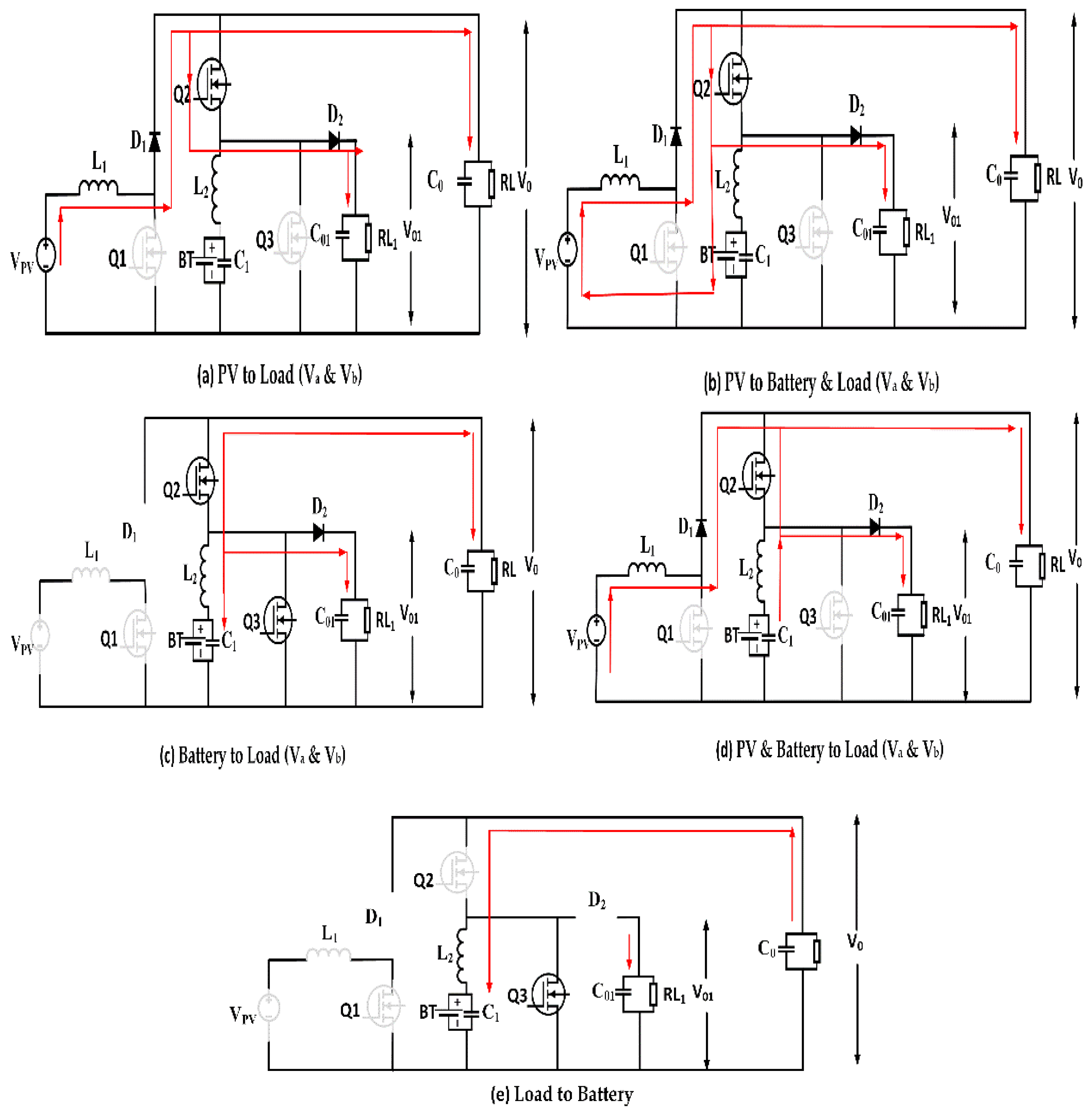
| No. of Modes | Power Flow | Bucking | Boosting |
|---|---|---|---|
| Modes 1 | PV to Load (Va & Vb) | - | Boost |
| Modes 2 | PV to Battery and Load (Va and Vb) | Buck | Boost |
| Modes 3 | Battery to Load (Va and Vb) | - | Boost |
| Modes 4 | PV and Battery to Load (Va and Vb) | - | Boost |
| Modes 5 | Load to Battery | Buck | - |
| Power Flow of TPC | Power Flow State of Mode When | Power Flow Analysis |
|---|---|---|
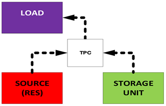 | Dual input (DI) state PV < PL | In this scenario, the battery is the only source of power for the load. |
 | Dual output (DO) state PV > PL | Both the main source and the battery are used to power the load in this stage. The input is the primary source, while the battery and load are the outputs. Excess electricity is also used to charge the battery. |
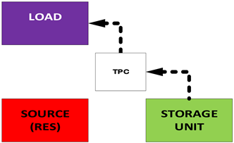 | Single input single–output (SISO) mode PV = 0 | In this scenario, the battery is the sole source of power for the load. |
| Converter | Topology | Loss and Stress Analysis | Power Output | Safety Stability Reliability |
|---|---|---|---|---|
| Two-input DC-DC converter [74] | The hybrid buck combines with three buck structure converters which give a high voltage-to-conversion ratio. DC input sources supply to the load individually or in parallel. Soft switching is usable. | When compared with quadratic converters, this gives a higher voltage reduction; hybrid converters store low energy in the magnetic field of the inductors. Hence, there are fewer switching losses. | It manages a large amount of output power. | It enables the employment of hybrid DC-DC converters in a dual-input configuration with a high voltage-conversion ratio. All of the modes of operation, analytical descriptions, digital simulations, and test results are in agreement. |
| Three-port grid converter power converters [71] | The boost’s basic topology. The TPC topology depicts a power flow in various operating conditions. | Multiple step conversion reduces system efficiency, which is a considerable loss. | The maximum power output is 200W. The switching frequency is 80 kHz, and the rated load power is 140 watts. | Effective use of a three-port standalone converter |
| Active multiport integrating multiple source and loads for grid [85] | This section describes a five-port converter. This multiport electrical interface topology connects PV, fuel cells, wind power, and batteries to a DC bus. | In non-isolated multiport converters, voltage and current strains are considerable. | This can process a stable output power for RES. | Stability and dependability demonstrate excellent performance. |
| Multiport DC-DC directional converter for PV battery system [86] | The suggested MPC has a straightforward topology with only four power switches. | Conduction losses are kept to a minimum, and voltage stress is kept to a minimum. | This can process a huge amount of output power. This is capable of processing a huge amount of output power. | It has a low level of stability and dependability. |
Disclaimer/Publisher’s Note: The statements, opinions and data contained in all publications are solely those of the individual author(s) and contributor(s) and not of MDPI and/or the editor(s). MDPI and/or the editor(s) disclaim responsibility for any injury to people or property resulting from any ideas, methods, instructions or products referred to in the content. |
© 2023 by the authors. Licensee MDPI, Basel, Switzerland. This article is an open access article distributed under the terms and conditions of the Creative Commons Attribution (CC BY) license (https://creativecommons.org/licenses/by/4.0/).
Share and Cite
Narayanaswamy, J.; Mandava, S. Non-Isolated Multiport Converter for Renewable Energy Sources: A Comprehensive Review. Energies 2023, 16, 1834. https://doi.org/10.3390/en16041834
Narayanaswamy J, Mandava S. Non-Isolated Multiport Converter for Renewable Energy Sources: A Comprehensive Review. Energies. 2023; 16(4):1834. https://doi.org/10.3390/en16041834
Chicago/Turabian StyleNarayanaswamy, Jayakumar, and Srihari Mandava. 2023. "Non-Isolated Multiport Converter for Renewable Energy Sources: A Comprehensive Review" Energies 16, no. 4: 1834. https://doi.org/10.3390/en16041834
APA StyleNarayanaswamy, J., & Mandava, S. (2023). Non-Isolated Multiport Converter for Renewable Energy Sources: A Comprehensive Review. Energies, 16(4), 1834. https://doi.org/10.3390/en16041834