Article

Characterization of the Operation of a BESS with a Photovoltaic System as a Regular Source for the Auxiliary Systems of a High-Voltage Substation in Brazil

by
Washington de Araujo Silva Júnior
1,2,
Andrea Vasconcelos
1,2,
Ayrlw Carvalho Arcanjo
1,*,
Tatiane Costa
1,
Rafaela Nascimento
1,2,
Alex Pereira
3,
Eduardo Jatobá
3,
José Bione Filho
3,
Elisabete Barreto
3,
Roberto Dias
2 and
Manoel Marinho
2
1
Edson Mororó Moura Institute of Technology (ITEMM), Recife 51020-280, PE, Brazil
2
Polytechnic School of Pernambuco, University of Pernambuco (UPE), Recife 50100-010, PE, Brazil
3
São Francisco Hydroelectric Company (Chesf), Recife 50761-901, PE, Brazil
*
Author to whom correspondence should be addressed.
Energies 2023, 16(2), 1012; https://doi.org/10.3390/en16021012
Submission received: 25 November 2022 / Revised: 26 December 2022 / Accepted: 5 January 2023 / Published: 16 January 2023
(This article belongs to the Special Issue Applications of Battery Energy Storage Systems (BESS))

Abstract

:
Substation (SS) auxiliary systems (SAux) are facilities responsible for hosting the alternating (AC) and direct current (DC) busbar to serve the equipment and systems that perform the substation’s protection, control, and supervision. External and internal power supplies typically ensure the continuity of such a facility. The electricity support will be restricted to diesel emergency generators (DG) if the external power supply is unavailable due to a contingency. The DG present a slower response time and are susceptible to starting failures. Microgrids with Battery Energy Storage Systems (BESS) paired with photovoltaic systems (PV) are presented as an innovative and reliable solution for powering the SAux. In this article, tests were carried out on the microgrid of the Edson Mororó Moura Institute of Technology (ITEMM) in Brazil to support the use of microgrids BESS/PV in the SAux of a transmission SS of the São Francisco Hydroelectric Company (Chesf). Without an external power supply, BESS commands the action of islanded operation, maintaining both voltage and frequency requirements of the microgrid without load shedding. It was possible to observe all operations of the microgrid. The experimental results showed that the solution proposed in the paper implements a dependable self-dispatchable autonomous power supply.

1. Introduction and Context

Substation auxiliary systems are responsible for the alternating current and direct current supply of the equipment that performs the substation’s protections, controls, and supervision. There are loads in the SAux that are essential; that is, they must be fed primarily, and non-essential loads, which can suffer interruptions for a longer period. Essential loads are those necessary to start the SS recovery process, in case of a total or partial shutdown [1,2].
Currently, the minimum requirements for Brazilian SS auxiliary systems are found in chapter 2.6 of the Brazilian National Electric System Operator (ONS). However, this chapter is the result of the reformulation of chapter 2.3, written by the same organization, which dealt with the same subject [1,2].
Chapter 2.3—Minimum requirements for SS and their equipment of the Transmission Power System Standard Document of the ONS—indicates that auxiliary systems of SS must have two independent sources of AC power supply. These sources may be internal or external to the substation. The internal sources come from the main transformers via a step-down tertiary winding of the SS itself, if existing, via a transformer dedicated to this function. The external sources come from a local concessionaire close to the SS facilities. It is also recommended that automatic switching between sources be implemented in the event of a failure in one of the sources so that the auxiliary system loads are not left unattended [2].
As discussed in Brazilian Electricity Regulatory Agency (ANEEL) Technical Note No.90/2019, a public consultation was opened to review chapters 2.3 and 10.14 of the Transmission Power System Standard Document [3]. This document explains the growing demand for flexibility and the incorporation of innovative solutions into the standard document, such as photovoltaic systems with a battery bank, as an alternative source of power for AC auxiliary systems. According to failure data obtained by the ONS in 2017 and 2018, the components that are most affected by failures in AC SAux are the reactive control and diesel generators. The DG has problems with the automatic emergency starting system. Table 1 presents the equipment most impacted by faults in the Brazilian Interconnected System (SIN) and the impact of their failure on the SS auxiliary systems.
There are operational records showing the difficulties in re-establishing systems associated with SAux. Thus, as shown in Table 2, eight records in the period from 2017 to 2018 were identified as taking more than 1 h to restore the SIN due to failures in the auxiliary systems. Among the listed problems, we emphasize the failures in the automatic coupling between the AC sources and failures in the 125 Vdc rectifiers, which indicates a loss of supervision and control of the SS. As mentioned previously, difficulties in the automatic starting system of the generator diesel are also highlighted.
Chesf has substations around these problems. Some SS do not have connections to the tertiary winding (internal source) and external sources provider of the same distribution point connection. Although there is DG presence, the studied Chesf Substation in this article presents contingency issues. The microgrid solution for this complex situation must allow more than 12 h of backup out of the grid. Accordingly, information about the substations’ AC auxiliary system faults provides subsidies for the search for innovative solutions that attribute high reliability and safety to the SS SAux. Figure 1 presents the real view of the high-voltage SS and its equipment with an indication of the Hybrid Battery Energy Storage System (HBESS) installation location.

1.1. Messias Substation Description

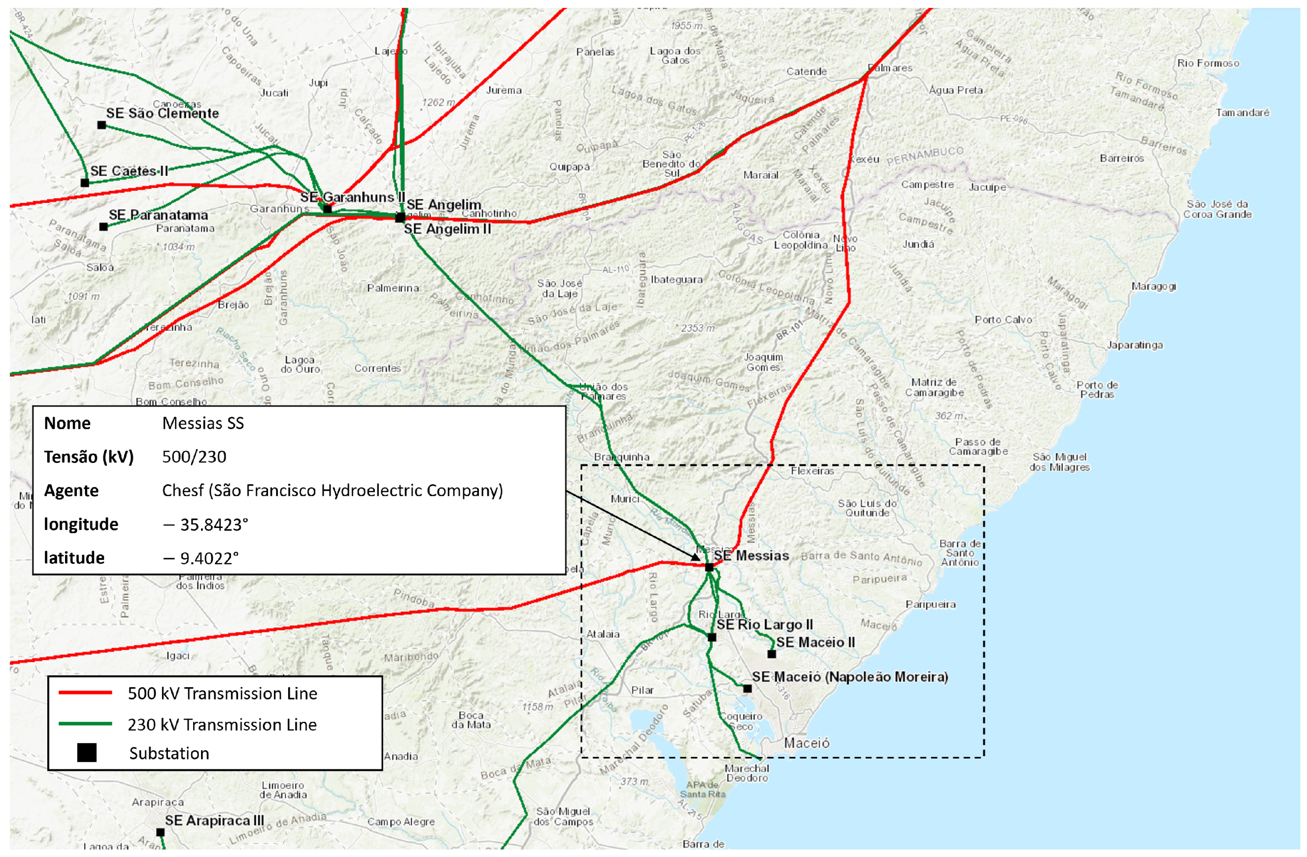
The Teotônio Vilela Chesf Substation—Chesf (popularly known as Messias Substation) is in Messias City, state of Alagoas—Brazil. As it is a substation that started operating before the existence of chapter 2.6 of ONS, it has inadequacies from the point of view of the ONS. Therefore, its facilities are being improved to meet grid procedures. Messias SS is a transmission substation which performs two functions: lowering the voltage from 500 kV to 230 kV and sectioning a 500 kV transmission line. The Messias Substation is part of an important 500 kV connection trunk, receiving a circuit directly from the Xingó HPP (3162 GW). Its availability is essential for the electricity support of the metropolitan region of Maceió, the capital of Alagoas, since it is critical for restoring the system in contingency conditions, as can be seen in Figure 2, due to the relatively high convergence, for the region, of transmission lines of 230 and 500 kV levels towards the substation.
A microgrid solution composed of an 877 kWp photovoltaic system, a 500 kW/1457 kWh Hybrid Batteries Energy Storage System (HBESS), and a 225 kVA motor-generator group (existing) will be installed at a high voltage substation in Brazil to operate as an autonomous source of supply of auxiliary systems of this SS. The developed solution is characterized by agility in performance and fault detection, with the intelligence to operate in islanded mode.
The HBESS and the photovoltaic system were dimensioned to guarantee 12 h of autonomy to the auxiliary systems of the SS in case of contingency in the electrical energy source external to the SS. In case of contingencies that extend beyond the 12 h of autonomy of the HBESS, the diesel generator will be used. It is considered as a backup of the HBESS.
The HBESS will operate as a network former (master) of the microgrid, reducing the number of inverters of the photovoltaic system that will enter the islanded operation. Microgrid control is possible through the Energy Management System (EMS) of the energy storage system, with the function of controlling the input and output of the microgrid components [5].
In the microgrid islanded mode, the HBESS converter must operate as a grid former and provide a reference voltage and frequency for the microgrid to operate satisfactorily. In addition, there will be applications related to the use of HBESS at the utility’s peak hours that supplies the auxiliary system of the SS (source 1), Volt-Var control for reactive control, power smoothing for the photovoltaics, and power factor control.
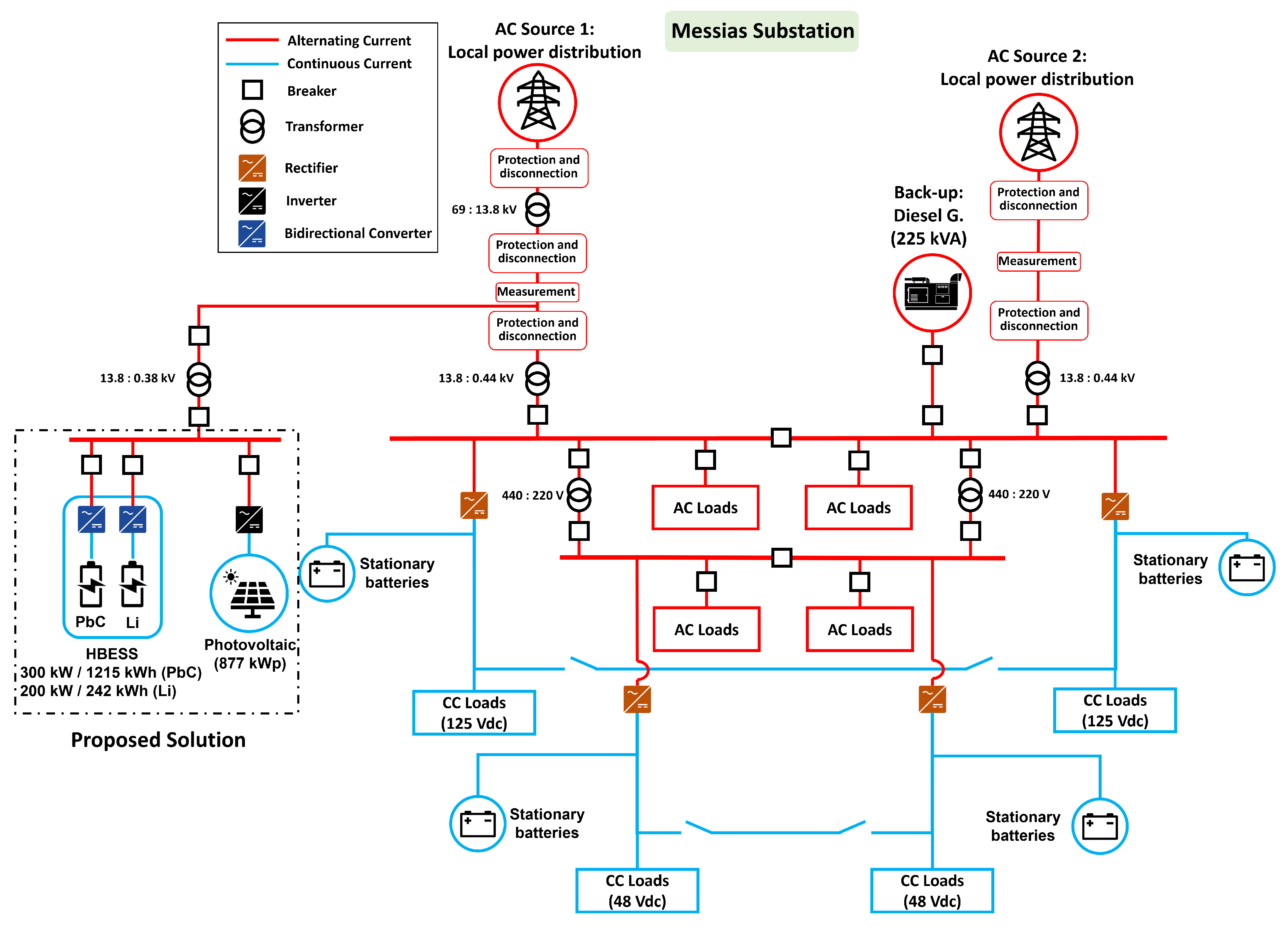
Figure 3 shows the simplified single-line diagram that covers the SAux of Messias SS. Source 1 comes from a local distributor and, as it is offered at a voltage of 69 kV, requires the use of a step-down transformer 69/13.8 kV to supply an auxiliary transformer of 13.8/0.44 kV, thus supplying the auxiliary system’s 440 V AC bus.
In case of unavailability of Source 1, Source 2 (also external of the SS) will be used, but both feeders come from the same distribution substation, which means that the sources are not independent. This contrasts with chapter 2.6 of the ONS. If source 1 fails, source 2 will probably fail, too. It is possible to use a diesel generator as a backup for this.
According to Figure 3, there is one diesel generator with 225 kVA (it has an automatic start-up) on the 440 Vac bus of the auxiliary system. DG, even with automatic start-up mechanisms, still offer interruption in the supply of energy to Saux, since, momentarily, after the absence of voltage on the AC bus, voltage is unavailable. This contrasts with chapter 2.6 of the ONS, which advocates an uninterrupted supply character [1]. Therefore, the use of such equipment is an environmentally outdated option [6].

1.2. Literature Review

This literature review comprised a brief theoretical foundation on BESS and its applications in electrical networks, hybrid arrangements of distributed energy resources, and the status of applications in electrical power substations.

1.2.1. Battery Energy Storage System

The history of battery integration in various applications started many years ago, and was mainly related to serving the electrical grid. Although BESS currently represents only a tiny part of the energy storage within most electrical systems worldwide, it is seeing significant recent growth due to its versatility, high energy density, and efficiency. More network applications became suitable for BESS as battery costs decreased, while performance and lifespan increased [7].
The IEC 62933-1:2018 standard [8] defines the electrical energy storage system as an installation connected to the grid from the Point of Connection (POC) with defined electrical limits composed of at least one storage facility capable of absorbing energy from the grid or other generation source, storing it for a certain period, and releasing it during periods of user need. These systems involve energy conversion processes from DC/AC converters, system management, sensing, protection, and auxiliary systems, among other components depending on the storage technology used and structural engineering works for the facility.
A battery energy-storage system is a subset of the ESS (Energy Storage System) that uses electrochemical storage. Typically, a BESS consists of a set of components, namely: (a) The batteries that store electrical energy in chemical forms, employing several technologies. The most widespread are lead acid, lead carbon, or lithium-ion, or a combination of those, which were used to assemble a Hybrid-BESS (HBESS); (b) Power Conversion System (PCS), responsible for converting alternating current (AC) into direct current (DC) and vice versa; (c) Battery Management System (BMS), responsible for measuring the temperature, current and voltage of the batteries, in addition to controlling and protecting against maximum and minimum voltage, current, and temperature. Another function is to estimate the state of charge (SoC); (d) Energy management system (EMS), which takes care of dispatching energy when charging and discharging the batteries, controlling the system and protecting it; (e) Temperature control system, known as HVAC (Heating, Ventilating, and Air Conditioning); and (f) Auxiliary systems, other components such as security system, fire system, sensors, and physical structure [9].
The PCS, BMS, and EMS are straight and strongly interconnected for the satisfactory performance of the BESS. The EMS can, based on the observation of the electrical grid and BESS applications, manage the control laws necessary for action on the grid. The EMS observes and controls the data from the BMS and PCS according to the schedule defined by the expert system. Finally, the control and data acquisition of the subsystems is performed by a SCADA (Supervisory Control and Data Acquisition) system. Depending on manufacturer integration, data may be available to the end user from an online platform [9].
Applications of BESS technology in electrical systems can occur at all levels of the electrical system (generation, transmission, distribution, and consumer) and are usually divided into five categories: energy supply, ancillary services, infrastructure services, transmission and distribution (T&D) support, behind-the-meter services, and renewables integration services [9]. Table 3 presents the categories and their related applications. Next, a brief commentary is made on each of the leading applications.

1.2.2. Hybrid Arrangements of Distributed Energy Resources

Hybrid power generation systems have a significant benefit in producing energy in remote locations, which are difficult to access, and where it is not economically viable to build local transmission lines to serve a residence or a group of people. They can also function as a complementation system between sources for the energy supply, reducing the interruption time the arrangement is subjected to. Different considerations must be considered when implementing a hybrid system and its configurations, such as the power of the converters and loads and the type of voltage—AC/DC—of the main bus of the grouping [10]. For the main bus (AC/DC) actuation mode, special consideration must be given to the type of load the system will feed and the type of generators for which the hybrid configuration is structured.
The photovoltaic power generation model can be coupled with different electrical systems to form a hybrid configuration, such as batteries, fuel cells, supercapacitors, wind generation, and others. The converters of a hybrid generation directly influence the system configuration. The type of connection (AC/DC) will define the behavior of the converters and the way the loads are fed.
The use of renewable energy has grown in recent years due to several factors, including the quest to improve environmental conditions and climate change. Photovoltaic generation is frequently used in this field, and its participation with the battery sets can power industries and small-scale households, communication areas, remote electrical generation, and power supply for the automotive industry, among other aspects [11]. The authors also draw attention to the growth in demand and quality of using BESS, highlighting that this more practical and efficient system has opened doors for battery bank applications in electrical systems.
An issue highlighted in some studies dealing with the association of BESS with solar-photovoltaic plants is the fact that the dispatch capacity of the PV-BESS arrays promotes excellent flexibility and energy security [12] for the electrical systems supported by the solution, since that even with advances in predictability algorithms [13,14,15] and hybridization of solar-photovoltaic plants by wind farms, in order to explore the existing complementary between these sources [16], the intermittency of solar-photovoltaic plants is a major constraint on the resilience of these sources as exclusive supply solutions.
The application of hybrid power supply systems can include different scenarios, and [17] shows that, in an environment where 16% of the costs of the sanitation sector in Brazil are allocated to electricity, the different connections between wind, photovoltaic, and diesel generation can be an excellent tool to reduce the costs of pumping a sewage lifting station when this system is coupled to the local electricity grid—which benefits in the sale of energy to the utility company, significantly reducing the cost of the project by not including the use of batteries; i.e., a system that is not coupled to the electricity grid—which also becomes interesting when the cost effectiveness of building a transmission line to suppress a load at a remote location is not feasible. There is also a possibility of using the photovoltaic system with diesel and battery, which brings a great benefit to implement in places such as some parts of Malaysia, where the population still does not have access to the electricity grid and only uses diesel generators on site, and the use of the hybrid system would reduce costs, increase reliability, and reduce the emission of polluting gases into the atmosphere [18].
A current issue is related to the use of advanced algorithms for the integration of renewable resources containing possibilities of using hybrid arrangements. In this regard, there are works that address optimal operation strategies for DC microgrids that use droop control [19]. Other articles address the optimal power that must be generated by renewable resources so that the cost is minimal for consumers. Thus, it is possible to develop generation management strategies for several renewable resources to supply the load [20]. Furthermore, it is known that microgrids may be subjected to events that challenge their operation, such as failures and extreme weather conditions. Therefore, it is expected that the MG management considers the most appropriate operation given the work conditions faced. In this sense, some authors have developed optimal methods that support the MG operator’s decision in order to maximize renewable production and MG autonomy [21]. All these points show the different lines of research that microgrids can provide.

1.2.3. Application of Hybrid Arrangements to Electric Power Substations

The use of a PV-BESS hybrid system consists of applying a solar-photovoltaic system paired with battery sets to improve the reliability of auxiliary systems in an SS.
Solar-photovoltaic systems as an independent distributed energy resource are strongly widespread in residential applications, providing a power supply in remote locations that do not have access to the power grid, or even supporting large transmission systems. However, its use is not limited to these scenarios; different cases of BESS-supported photovoltaic energy use for the operation of substation systems have enhanced the application of independent solar plants.
These applications, as individual solar plants in different areas, were present in the 1990s when a photovoltaic arrangement was implemented, for instance; in a substation in California—USA, to reduce losses in the Distribution system. This energy support system reduced substation energy losses by up to 6% and could also increase the time between equipment maintenance intervals, increase the reliability of the distribution system, and postpone transformer upgrades, among other functions [22].
Even in the 1990s, studies were carried out on solar-photovoltaics systems to supply the operating systems of a switching substation, demonstrating that the final costs were more affordable using a photovoltaic system in contrast with conventional systems [23].
A practice that has become increasingly recurrent nowadays is the replacement of particular sources of electricity with solar-photovoltaic energy, aiming at savings in the total tariffs and costs arising from using these sources and meeting more objective sustainability criteria. In substations, it is no different; the supplies necessary for the operation of auxiliary services can represent a considerable cost for the maintainers of the SEs, and reducing them in a strategic way becomes relevant for the intrinsic profits of the enterprise in addition to the reduction of the environmental impact caused.
In addition to the applications and functions already presented, another relevant issue involving photovoltaic panels is the cost–benefit ratio enabled by photovoltaic generation.
Batteries are also used in substations for different functions in the local electrical system. In the use of BESS in substations, the location of the battery scheme can directly influence the system losses and the influence on the electrical grid, with BESS installed in local substations demonstrating a better performance in reducing losses and in power compensation [24]. Pairing a solar-photovoltaic array with a BESS can be helpful in processes that involve supplying the auxiliary services of a system. Solar-photovoltaic panels have fluctuations in their energy generation during the day, consequently impacting their efficiency and electrical energy supplied to the set. Additionally, as shown in [25], the PV-BESS plant can reduce the fluctuations caused by solar-photovoltaic generation, reducing the difference between the predicted generation and the actual generation, resulting in lower costs for companies which allow the BESS to be allocated in different ways in the plant to provide a more efficient method of operation. In addition, the authors also address that this BESS can be coupled to the auxiliary service of the system to delimit peak values and fill moments of low energy flow.
The reference [26] demonstrated a multipurpose planning and control method for applying solar-photovoltaics paired with BESS in Distribution. The authors conclude that BESS in photovoltaic plants can reduce the tap operations of the LTCs and the photovoltaic plant’s cut-off range. This application, however, fits in situations where a large-scale BESS is used.
Regarding the specific applications object of the research enclosed in this report, an international mapping was carried out to find, in international TSOs/RTOs grid codes, connection agreements and grid requirements documents [27,28,29,30,31,32,33]. Evidence of application of the solution is presented here, demonstrating the supply of SS Saux by PV arrays paired with BESS; no forecast of use of the solution was identified.
Seeking for international studying the nowadays commercial projects of PV-BESS arrangements in primary or secondary Distribution networks, the Global Energy Storage Database (GESDB) of the United States Department of Energy was used as a freely accessible database of energy storage projects and policies funded by the US DOE, and maintained by the laboratory of Sandia National Labs, of the US government and updated until 2021, for carrying out bibliographic searches.
The database (DB) has a mapping of more than 1700 worldwide electrochemical, electromechanical, and thermal storage projects. Of the 427 BESS identified as in operation, 25 specific worldwide projects of SPV-HBESS arrays connected to Distribution were selected, given the completeness of information available in the Base.
Regarding services to the Distribution sector, the technology application hierarchy focuses on system reliability, increasing supply capacity, use of electric vehicles, and, finally, non-wired alternatives (NWA).
Still, according to the analysis extracted from the GESDB of the ESS applications worldwide, arbitrage is the most frequent application, at 24.77%. Capacity Firming, which uses batteries to eliminate rapid fluctuations in voltage and power in the electrical grid resulting from intermittent sources (SFV and wind power plants, mainly), is currently responsible for 13.24% of projects [34].

1.3. Main Contributions

The mapping performed by the authors showed that the specific application related to power supplying a Saux of a Transmission SS using a PV-BESS arrangement was not deeply studied worldwide. That makes this paper, and its results, a relevant source of information about the theme, as one can see in subsequent sections.
All of the points mentioned illustrate why a solution utilizing battery energy storage systems is a great proposal. This system possesses all the advantages of batteries, as well as renewable energy sources, which can be used as a new way to supply uninterrupted energy to the auxiliary systems of SS. The microgrid solution was a response to the request of the Chesf public call to receive project proposal(s): photovoltaic mini generation using battery energy storage as an autonomous source of supply of auxiliary systems of 230/500 kV substations with internal source constrain [35].
This article contributes to the operational validation of the microgrid solution developed to provide a continuous supply with reliability requirements of the auxiliary system of transmission substations. The results were obtained based on tests in a commercial reduced-scale microgrid with connected and islanded operations. Furthermore, it was possible to observe the behavior of the microgrid components in terms of voltage and frequency in each operating situation and their stabilization during their transitions.

2. Materials and Methods

The scientific research procedures applied within the scope of this work were accomplished in two steps: (a) a theoretical (preliminary step) and (b) an experimental (primary step).
The preliminary step of the research applied a deductive method approach through a systematic review concerning the pairing of BESS with solar-supplied microgrids in similar characteristics of a Saux of a SS part of the Transmission subsystem.
Due to this step’s qualitative and documentation-based biases, we did not use specific materials resources but studied and analyzed relevant papers hosted in web repositories of scientific literature, as well as publications written by the authors themselves, focusing on legitimizing the contribution through relevant scientific journals and magazines.
The primary step—namely the experimental tests—were thought to demonstrate the proposal’s effectiveness in applying the BESS paired with a solar-photovoltaic plant solution to supply power to a SS’s Saux. The tests took place over the outdoor commercial microgrid of ITEMM on 3 August 2022, in Belo Jardim, PE, Brazil, which has a scale representation of approximately 1:3, concerning the facility’s structure of auxiliary services of the Messias substation, according to Table 4.
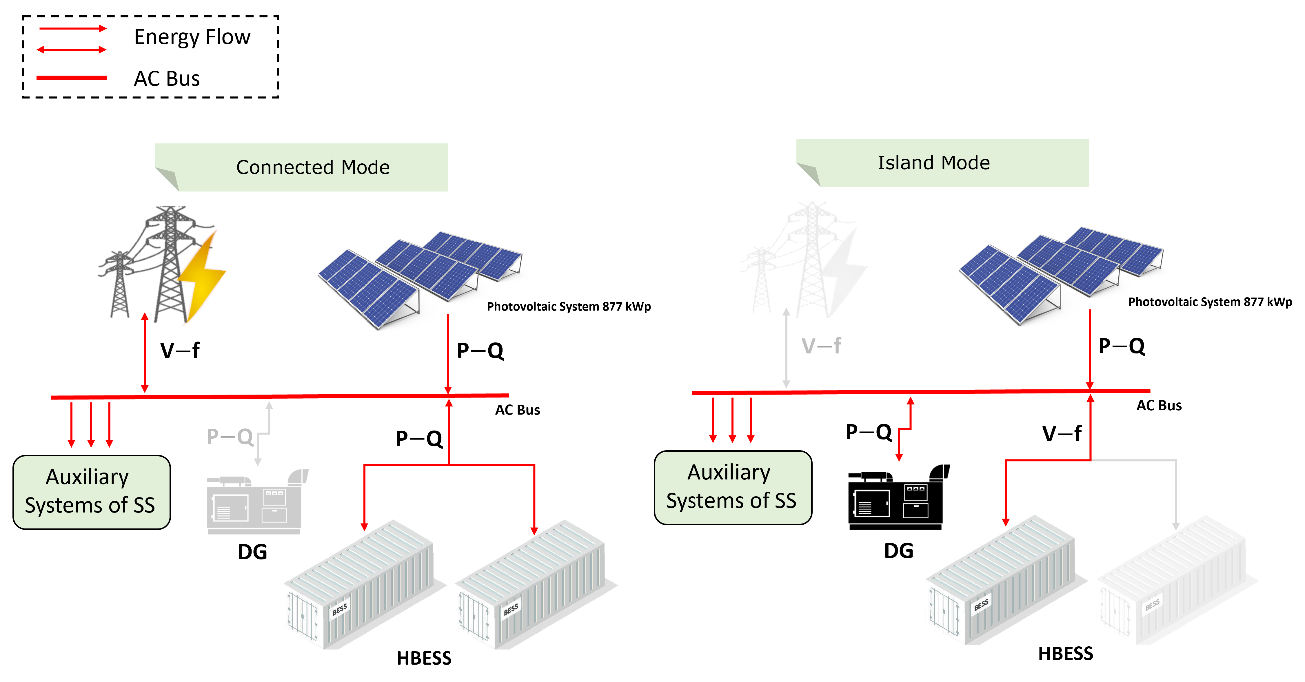
The developed solution has components connected to the AC bus, master–slave control mode for the microgrid and P–Q and V–f control of the converters. When the system is connected to the grid, the system master is the grid (V–f), while the HBESS and the PV system operate in P–Q mode, providing active and reactive power. In the event of an interruption to the mains power supply, the HBESS will transition to islanded mode. Thus, the HBESS system with the highest energy will operate in V–f mode, while the other will remain in standby mode. The photovoltaic system will operate at reduced capacity to respect the conversion capacity of the HBESS PCS. In this way, it is possible to mitigate the effects of variations in the active power of photovoltaic generation that can interfere with the quality of the microgrid’s energy. In the case of a critical SoC of the system that is in operation, there will be a transition from that system to the other HBESS, Figure 4. Soon, one will go into standby mode while the other HBESS system will come into operation [5].
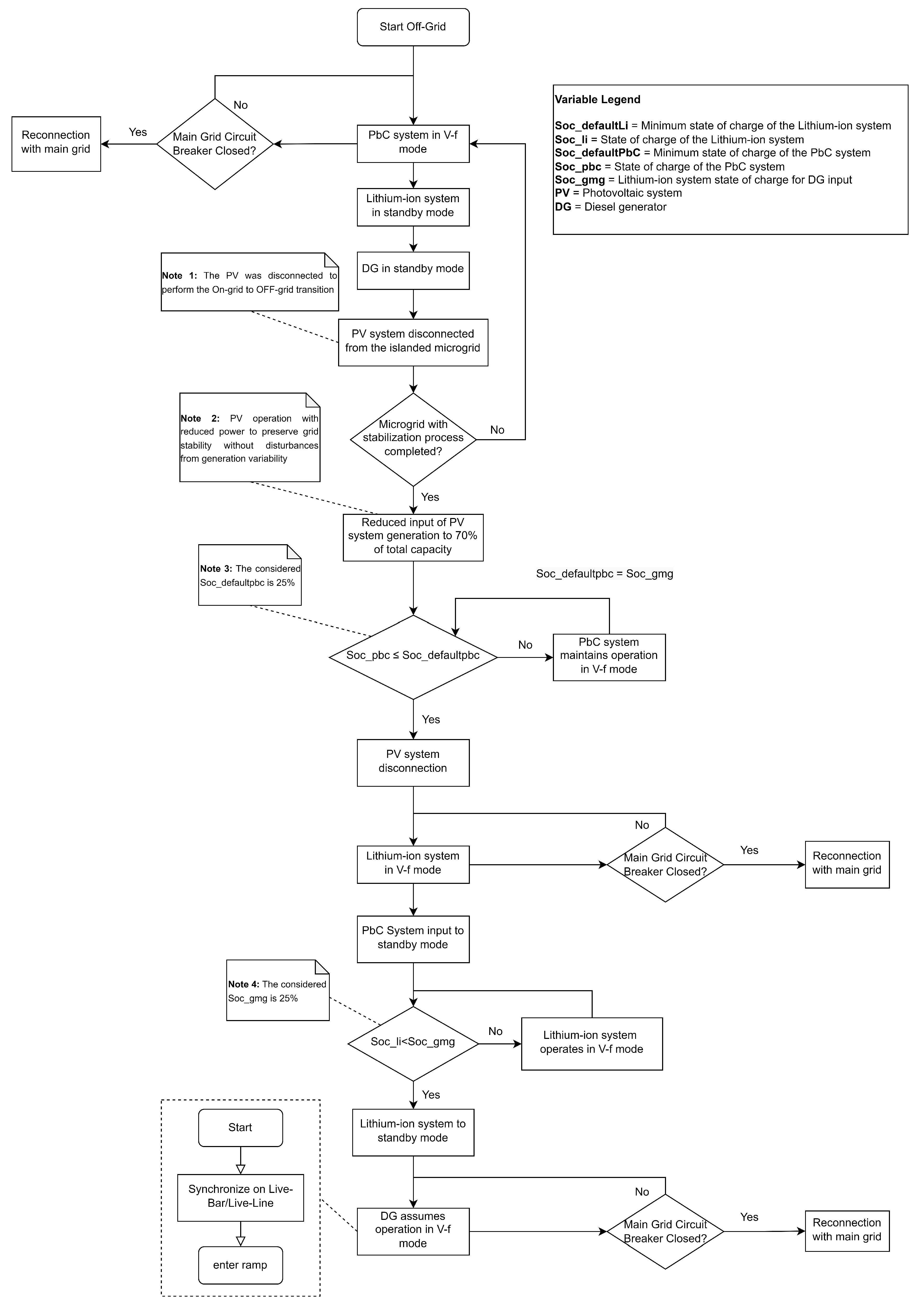
Figure 5 shows the performance flow of the main off-grid scenario. Thus, as described in the respective figure, after the contingency event has started, the process of automatically disconnecting the microgrid from the main network immediately starts. In this scenario, the bank of lead carbon batteries (Pb–C) becomes the grid voltage and frequency reference. As soon as the grid is stabilized, the photovoltaic system has its production reduced to 70% of the nominal. The network continues to be served by these sources until the charging level (SoC) of the PbC battery bank reaches 25% of its nominal capacity. At this point, the PV system is disconnected and the lithium-ion battery bank assumes the voltage and frequency reference of the microgrid. Loads, in their entirety, are maintained by this source until it reaches 25% of its nominal SoC capacity. When this event occurs, the 225 kVA diesel generator assumes responsibility for the loads until it is possible for the microgrid to be reconnected to the local utility’s power distribution network.

3. Experimental Tests

The experimental tests took place in the microgrid of the ITEMM on 3 August 2022 in Belo Jardim, PE, Brazil. To validate the implementation of the microgrid that will be deployed at Chesf’s Messias SS, adjustments to the ITEMM microgrid were necessary.

3.1. Assumptions Considered during the Tests

Some previous scores should be considered regarding the tests:
(1)
The ITEMM microgrid exclusively uses a battery energy storage system with lead-carbon technology (BESS 1). However, the Messias SS microgrid will feature two different technologies (lithium-ion and lead carbon). Therefore, the representation of these systems in the ITEMM microgrid is given in power, in which the 1:3 scale is considered in Table 4;
(2)
The tests focused on islanded operation, given the sensitivity of disturbances appearing during the transition and off-grid operation;
(3)
To represent the Messias SS load, a second storage system (BESS 2) was used, consuming energy from the microgrid, and configured for 40 kW of maximum active power absorption;
(4)
Knowing that the main load of the ITEMM microgrid that represented Messias SS is a small energy storage system (BESS 2) performing recharging, after its State of Charge (SoC), it presents a high level, causing internal resistance of the battery for absorption of energy. For this reason, it was necessary, in some parts of the tests, to discharge the BESS 2 in the main storage system (BESS 1);
(5)
Due to the SoC being close to 95% of BESS 2, at times, a 22 kW charging station with an electric vehicle and resistive load (30 kW maximum) was used to complement the power established for the load;
(6)
The charging station’s power varies according to the electric vehicle’s (EV) SoC. Thus, it was observed that the active power consumption of the microgrid achieved by this system varies with a negative derivative; that is, the EV charging process starts with high power and reduces as the SoC increases;
(7)
The diesel generator was operated on with 20 kVA.

3.2. Test Topology Microgrid

To properly interpret the results, it is necessary to understand the topology of the ITEMM microgrid adapted for carrying out the tests.
Figure 6 shows the microgrid measurement points. The BESS 1 EMS readings were collected from the PV inverters, diesel generator, BESS 1 Power Converter System (PCS) output, main grid input, and Static Transfer Switch (STS) output of BESS 1 directed to loads (BESS 2, resistive load, electric vehicle charging system) [36].
The EMS measurement performed at the BESS 1 STS output, which is responsible for measuring the load magnitudes, is found before the PV system and diesel generator are coupled. This means that in islanded operation, when the PV or diesel are in operation, BESS 1 will discharge complementary power to supply the loads (the consumption of BESS 1’s auxiliary loads being included as a load). Another highlight is associated with the charging of BESS 1. Thus, when the SoC of this equipment presents low levels, it can be charged through photovoltaic generation (if available) or any other source that supplies power.
In addition, since BESS 1 is the grid-forming and microgrid power flow manager (balance between generation and load), at times of high-power penetration or low generation of sources, this equipment can absorb or inject power to maintain the balance and power quality of the microgrid.
The points measured by Power-Quality Analyzer were the output of the Power Converter System (PCS) of BESS 1, the AC output of photovoltaic inverters (1 and 2), and the input of BESS 2 (main load).
Furthermore, the technical specifications of all microgrid components are shown in Table 5. All the microgrid equipment is commercial.

3.3. Physical View of the ITEMM Microgrid

The physical view of the main components of the ITEMM microgrid is shown in Figure 7. Thus, it is possible to identify the 250 kW/560 kWh BESS 1, two 36 kW photovoltaic inverters, photovoltaic panels, and a 75 kVA diesel generator.

3.4. Experimental Test Plan

Testing procedures have been developed to support the necessary microgrid analysis. The objective is to evaluate BESS’s operating conditions and performance when it is in the configuration: (i) grid-feeding (P–Q); (ii) grid-forming (V–f); (iii) in V-f mode with PV system input; (iv) in V–f mode with diesel generator input; (v) in the transition from connected (BESS in P–Q mode) to islanded (BESS in V–f mode) with load; and (vi) in the reconnection of the microgrid with the main electrical grid with the load.
The tests were conducted in a situation of unintentional islanding at the main source, in which BESS 1 must form the microgrid and maintain the supply of energy to the loads and, in the event of the restoration of the main grid, to initiate reconnection to the electrical grid and switch the BESS 1 from grid forming mode to grid feeding mode.
Table 6 presents the operating scenarios that were investigated in the tests carried out on 3 August 2022. Notably, the tests described were based on the recommendations of the IEC 62898-1, IEC 62898-2, and IEEE 2030-8 [37,38,39] standards.
The main aspects that must be observed in the tests are listed below.
  • BESS 1 test operating in grid-feeding mode (P–Q): When we operate the microgrid in a connected mode, the main electrical grid is responsible for the stability of the microgrid components, as its main function is to provide the voltage references and frequency for synchronizing distributed generation equipment—in this case, the photovoltaic system and the battery energy storage system. Several applications can be performed with a BESS operating grid connection, such as demand control, reactive control, and power smoothing [40]. The expected result of the test is BESS operating as a follower of the V and f references of the electrical grid and performing its predefined functions in this scenario. Articles [41,42] present details of the grid-feeding mode of operation.
  • Test of BESS 1 operating in grid-forming mode (V–f): When the microgrid operation is connected to the main electrical grid, generation and consumption in the microgrid typically have no restrictions on their operations or on the energy levels they can inject or consume from the grid. In the case of islanded operation, there are limitations related to the power and energy levels between the components that compose it. In this sense, after the BESS enters backup mode, the microgrid in islanded operation receives voltage and frequency reference from the PCS. EMS management is needed achieve the optimal energy balance between the microgrid components. In this aspect, the expected result is that the BESS can operate, offering V and f reference for the microgrid, and maintaining the power quality at adequate levels. Articles [41,42] present the details of the grid-forming mode of operation.
  • Test of BESS 1 in V–f mode with input from the photovoltaic system: During islanded operation, it is expected that the BESS will be able to mitigate the effects of sudden high active power input into the microgrid. The active power of the PV system influences the microgrid voltage, causing this parameter to rise and fall during high power variations. In addition, when the generation is greater than the load, there are variations in frequency, voltage, and power factor reduction. Thus, adequate microgrid sizing is reinforced to ensure a balance about renewable generation and loads.
  • Test of BESS 1 in V–f mode with diesel generator input: In islanded operation, the diesel generator input causes high penetration of active power in the microgrid, influencing the voltage and frequency of the islanded system. The behavior presented is similar to the PV system input in the islanded grid. It is expected in this test that the BESS, after the entry of the diesel generator, will be able to stabilize the voltage through its Volt-Var control and the frequency through its absorption of excess active power.
  • Test of BESS 1 connected to islanded transition with load: Unintentional islanding occurs without any predictability, due to main grid failures, equipment failures, and events of the same nature [43,44]. These occurrences make it impossible to implement previous adjustments to the microgrid and its components. Therefore, this type of islanding can result in severe transients to the microgrid and make operation stability in islanded mode difficult. In this sense, the balance between the microgrid’s load and generation and the controls is used to define the operation’s continuity in the microgrid’s islanded mode. It is expected in this test that BESS can carry out the transition and stabilize the microgrid formed due to unintentional islanding.
  • Test of BESS 1 reconnection with load: The microgrid reconnection, changing from the operation in islanded mode to connecting to the main electrical grid, is a fundamental step in the operation cycle of a microgrid. This is a time when BESS returns voltage and frequency control to the main electrical grid. It is expected in this test that BESS can perform the change from the grid forming operating mode to the grid follower mode and continue performing the P–Q applications predefined in this scenario.

4. Results

In this topic, the experimental results obtained in the microgrid are analyzed and interpreted. The tests were conducted considering all possible operations planned to validate the solution developed for Messias SS/Chesf.
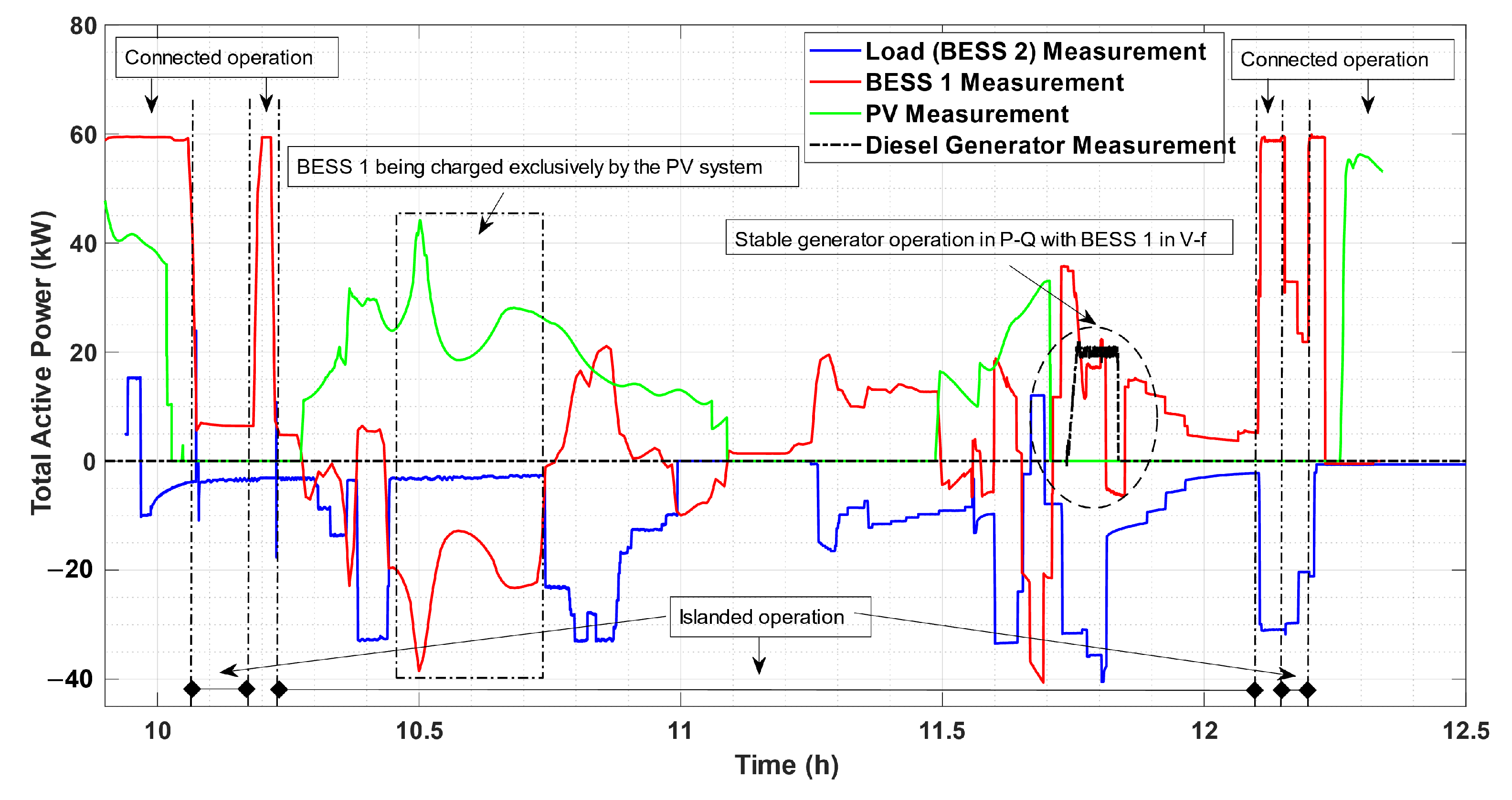
On that test day, there were three scenarios of islanded operations with the intention of evaluating BESS 1 in consecutive situations of unintentional transitions, due to a failure of the main electrical grid. The most extended period of islanded operation started at 10 h:12 min:45 s and ended at 12 h:05 min:45 s; that is, the operation lasted 01 h:53 min:00 s. In the islanded operation condition, two PV inverters with the same nominal power (36 kW) were inserted; a diesel generator configured with a rated power of 20 kW; BESS 2 configured to operate with an inductive behavior and with a recharge power of 40 kW; resistive load with maximum power up to 30 kW; and a charging station capable of recharging the EV with 22 kW. Figure 8 shows the operating condition of the microgrid based on EMS data from BESS 1.

4.1. BESS 1 Operating in Grid-feeding and Grid-Forming Mode

The voltage and frequency values of BESS 1 obtained through a power analyzer are shown in Figure 9. The ranges of operations islanded and connected to the grid are observed. In islanded mode operations, BESS 1 is the grid-forming and, therefore, voltage and frequency reference for microgrids. In this condition, it is possible to observe the power quality improvement and the suitability to the steady-state voltage and frequency limits established in the Distribution Procedure (PRODIST) Module 8 [45], as shown in Table 7. In the periods of operation connected to the grid, the BESS 1 follows the voltage references of the main electrical grid. Furthermore, Figure 9 shows, between 11 h:30 min:00 s and 12 h:00 min:00 s, transients in voltage and frequency because of the input of the PV and diesel generator in the islanded microgrid.
It can be considered that islanding 2 was the most severe for the microgrid, due to the insertion and variation of active power of the PV system and, later, the input of the diesel generator. However, it can be seen that the maximum voltage value recorded on island 2 was 0.4% above the reference value, while PRODIST established a maximum value of 5%. For the minimum voltage value, a dip of 0.1% below the reference value was recorded in this islanding, while PRODIST established 8%. With regard to frequency, the reference was maintained throughout islanding time 2. These points reinforce compliance with the distribution procedure and also improve energy quality, even in the most severe islanding condition.
As we know, the most severe islanding for a microgrid is unintentional, as it comes from a failure in the main electrical grid. All three islanding options presented were of the unintentional type. In this aspect, an optimal balance between load and generation is required from the microgrid so that the islanded operation is stable and adequate for the limits of power quality [46]. Compliance with the power ratios of the microgrid components must be considered so that islanded operation is possible without the need for load reduction [46]. In this way, it is possible for the microgrid to operate stably in a situation of sequential contingencies in the main electrical grid.

4.2. BESS 1 Operating in Grid-Forming Mode with PV System and Diesel Generator

Figure 10 shows the active power values of the microgrid components, obtained using a power analyzer. In this figure, it is possible to perceive two highlighted moments; the first of them is presented in the scenario in islanded mode. Due to the availability of photovoltaic generation and BESS 1 presenting low SoC, there was a recharge operation of BESS 1 through the photovoltaic system. This measure, if desired, is an excellent alternative for extending the operating period of the islanded microgrid. It is important to note that BESS 1 recharged with excess energy from the PV system without impacting the attendance of the load by solar generation.
The second moment depicts the exclusive entry of the diesel generator to the local grid; that is, without the presence of the photovoltaic system. The diesel was configured to operate in P-Q mode, so, when activated, this component injects power into the microgrid. Before the entry of the diesel, the BESS 1 exclusively supplies the consumption of the loads. When the diesel input is detected by the EMS, BESS 1 acts by reducing the power it was injecting to supply the loads and provide a balance between all the powers available in the microgrid, together with the demand requested by the load. Stable operation of the diesel generator in P-Q mode is also observed, with BESS 1 forming the grid.
Furthermore, Figure 11 shows the voltage of the diesel during the period of operation of this component collected through the EMS of BESS 1. The most critical moment for this scenario is the generator input. The generator voltage rises to 1.17 p.u. This event is characterized by PRODIST as a momentary voltage increase because it has an amplitude greater than 1.1 p.u. and a duration between 1 cycle and 3 s [45]. It is important to realize that there are no standards that limit the occurrence of short-term transient variations; however, such an event cannot cause an equipment malfunction. Thus, as can be seen in the behavior of the microgrid, shown in Figure 9, there is suitability for the ranges established by PRODIST during the transient event and after it. In addition, the diesel generator voltage, after the transient event, is kept within the PRODIST limits and follows the reference of the network former (BESS 1).

4.3. BESS 1 Operating on Connected to Islanded Transition with Load

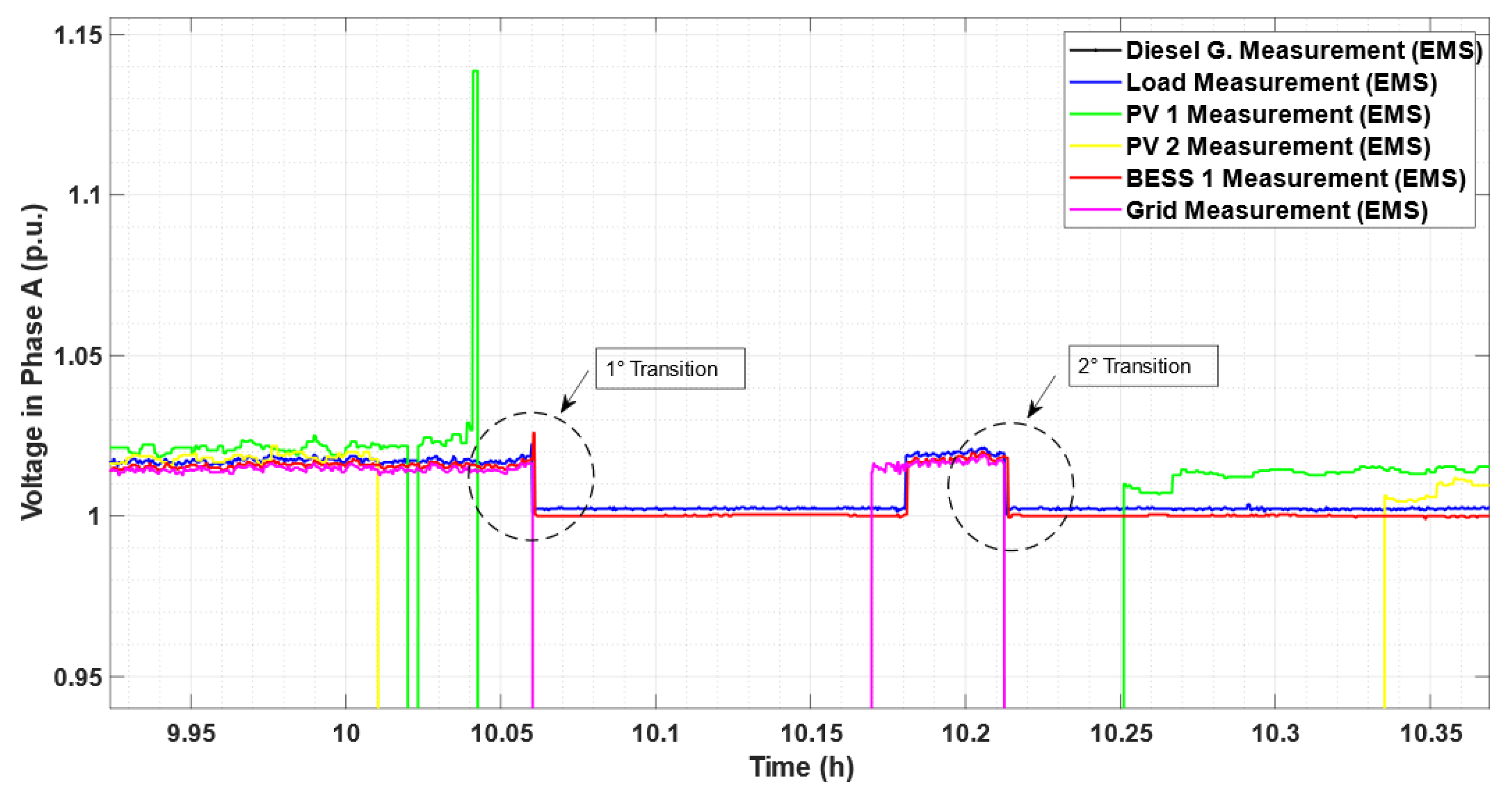
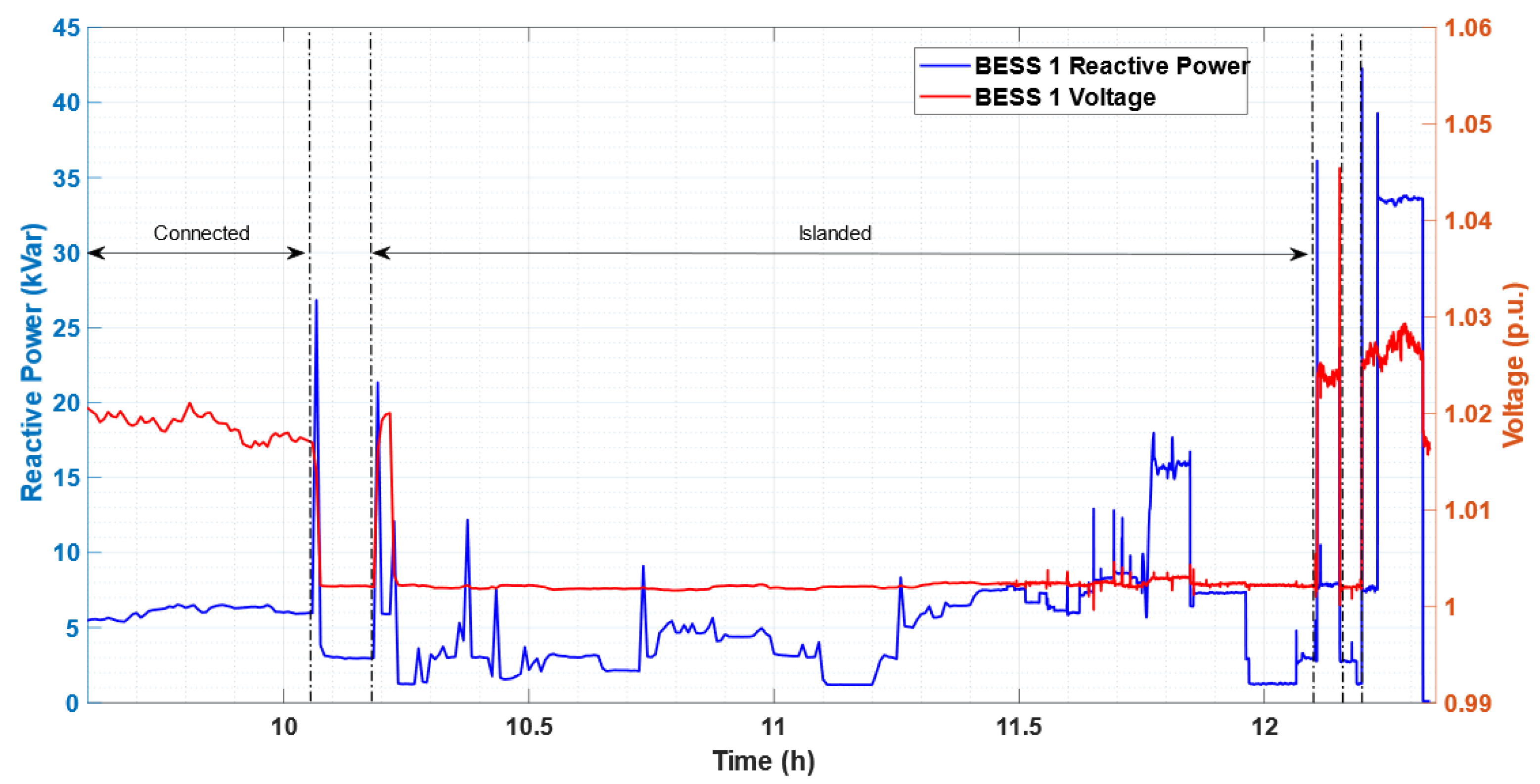
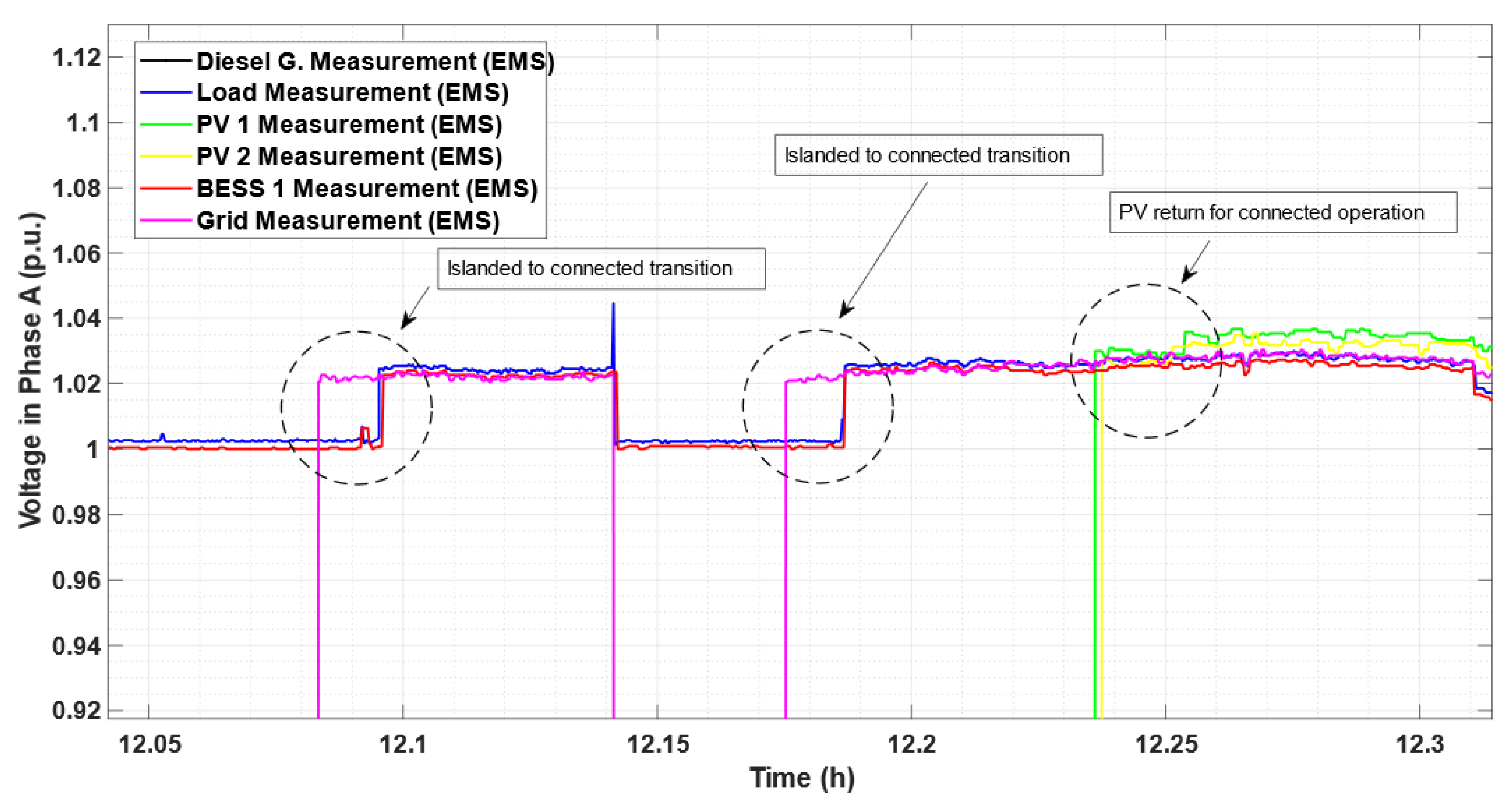
Figure 12 shows the voltages of the microgrid components collected by EMS. This result presents highlights two moments of transition from connected to islanded mode, evidencing the improvement in power quality in islanded operation, where BESS 1 provides the grid forming. Furthermore, the voltage behavior in the transition depends on the microgrid situation at the time of the event in relation to power availability and load demand. Therefore, in the first transition, a small transient voltage rise of 1.026 p.u. resulted from the sudden increase in reactive power of BESS 1, Figure 13, requested by the microgrid for stabilization and power balance for island operation. The same happens in the second transition, but the voltage increase is imperceptible due to the lower injection of reactive power used at that moment by BESS 1.
Figure 13 illustrates the behavior of the voltage and reactive power of the grid forming in the test. The most expressive result is observed in the transition that occurs smoothly without causing tension disturbances, despite being due to unintentional islanding. It is also observed that between 11 h:00 min:00 s and 12 h:00 min:00 s, there was a contribution from photovoltaic generation and from the diesel generator, in which BESS 1 can be seen operating in the injection of reactive power to control the voltage of the microgrid at that moment.
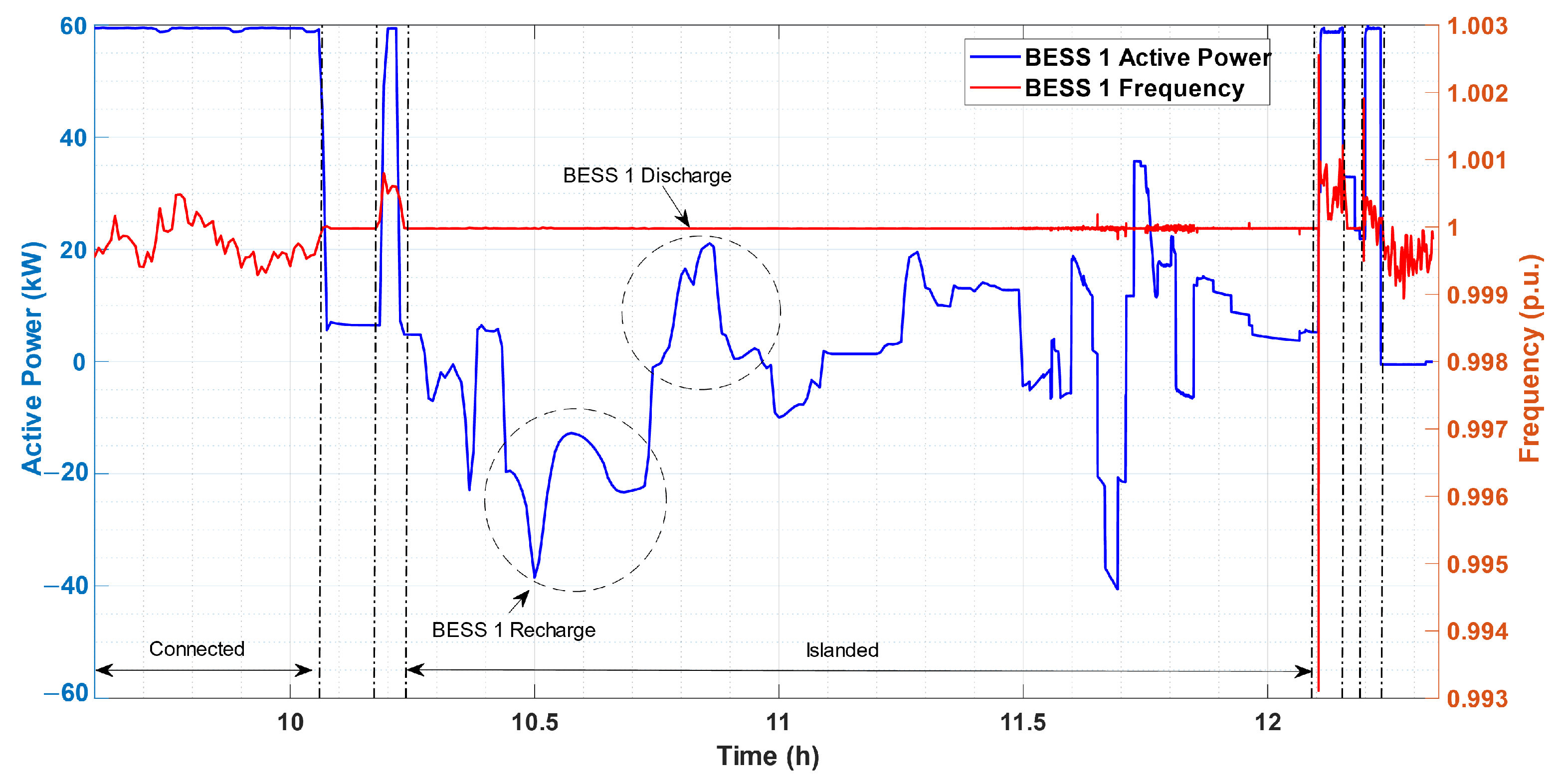
Figure 14 shows the observed transition from the point of view of frequency (red line) and active power (blue line) of BESS 1, making it evident that the transition occurs smoothly without causing frequency disturbances, despite being due to islanding and not being intentional. The results highlight two distinct moments of BESS 1 that are common in the islanded operation of a storage system in conjunction with a photovoltaic system. The first, BESS 1, performs recharging (negative active power reference) through the photovoltaic system. The second, BESS 1 performs discharge (positive active power reference) to supply the loads. In both moments, no disturbances are observed in the frequency of the grid forming.

4.4. BESS 1 Operating on Reconnection with Load

Figure 15 emphasizes the operation of reconnecting the microgrid with the main electrical grid. In this situation, BESS 1 makes the transition between grid-forming and grid-following modes (V–f → P–Q), so the main electrical network assumes the voltage and frequency references. After this transition, a reduction in the power quality supplied in connected mode is observed. In addition, it is observed that there is a time to carry out the reconnection to the electrical grid. This time is related to the technical characteristics of the converter. Synchronization with the power grid can vary from seconds to minutes.

5. Discussion

A microgrid can operate connected to the grid (on-grid) or in islanded mode (off-grid) under defined electrical limits. An off-grid operation with adequate levels of power quality is dependent on several factors. To ensure the development of an optimal solution for islanded operation, it is necessary to analyze the daily behavior of consumption, maximum and minimum power, voltage, and operating frequency of loads, and the characteristics and limitations of the available distributed resources.
Microgrids must have an efficient and reliable system for monitoring the parameters of their constituents. Thus, through this information and verifications, the microgrid main control can perform the transition of operating modes properly and reliably. In this sense, the main findings observed in the experimental tests on the ITEMM microgrid were the following:
  • It was observed in operation connected to the grid that the BESS in the grid-feeding mode, acting as P–Q (power injection or absorption), performs all the proposed applications; for example, it is possible to observe in the results of the demand control or reactive control;
  • In islanded operation, BESS was visualized as a voltage and frequency reference for the microgrid, in which a significant improvement was observed in the microgrid power quality;
  • The results showed BESS acting and maintaining power quality in different scenarios on the same day, leading to grid forming because of sequential unintentional islanding. This type of islanding occurs without any predictability due to faults in the main electrical grid and, in this sense, they are considered very severe for a microgrid;
  • It has been proven that, as a grid-forming technique, BESS can recharge through a photovoltaic system without impacting the voltage and frequency quality of the microgrid and the load supply;
  • It was shown that BESS, as a grid-forming technique, can maintain power quality levels with the power variation of the photovoltaic system;
  • BESS in V–f mode can manage a microgrid with PV inverters operating in parallel, since the power proportions of BESS with the PV system are respected;
  • It can be observed that in moments of unavailability of photovoltaic generation, BESS supplied the demand requested by the loads;
  • The result showed that BESS could match its power to complement the input of a diesel generator or PV system in islanded operation. In this aspect, the load was supplied with power from the BESS and the generator or PV system;
  • It was observed in the islanded operation that the BESS (in V–f mode) could stabilize the voltage and frequency even because of the starting peak of the diesel generator set input;
  • It was proved that the BESS (V–f mode) performs the energy balance between generation and load during the entire islanded operation, maintaining the microgrid power quality.

6. Conclusions

Microgrids, intelligent systems that integrate distributed generation resources, energy storage, and loads, can mitigate the effects of contingencies. Using microgrids, it is possible to operate while connected to the electrical grid and, in contingency situations or programmed events, to operate in an islanded way, providing voltage and frequency balance in the isolated grid formed, establishing supply, and increasing reliability for the loads. In this context, this article presented the contextualization of the use of microgrids for a continuous supply of critical loads in contingency situations, such as auxiliary systems of substations. This microgrid solution, composed of BESS and PV system, guarantees a quick response when compared to the current backup of these SS, such as diesel generators, which are known in the electric sector for presenting difficulties related to their start-up in a timely manner to avoid missing the substation.
Linked to this theme, the main contribution of this article is the experimental tests carried out in the ITEMM microgrid, in Belo Jardim, Pernambuco. This microgrid is composed of commercial components, which were exposed and discussed to validate the applicability of the microgrid that will be installed in Messias SS. The aim was to evaluate the operational concept of the microgrid to be installed by Chesf, containing a HBESS and PV system, through real electrical tests. The results from the testing showed that the voltage levels stayed within the allowed ranges, ranging from 0.92 pu to 1.05 pu. The same result was observed in the frequency behavior, with a stable frequency around 60Hz, suffering few variations without breaking the power-quality limits. This shows that, even with variations in the active power output of the PV system, the PCS has the capacity to maintain the formation of the grid. Additionally, the battery system quickly absorbs and injects energy without affecting the power quality of the microgrid.
Thus, the proposed solution to solve the Messias substation problem was tested and found to operate successfully, proving the continuous supply of AC auxiliary systems. The next steps include installing the microgrid in the substation in question and performing the assisted operation analysis.

Author Contributions

Conceptualization, W.d.A.S.J., A.C.A., T.C., A.V. and R.D.; methodology, W.d.A.S.J., A.C.A., T.C., A.V. and R.D.; validation, T.C., A.V., A.P., E.J., J.B.F., M.M. and E.B.; formal analysis, W.d.A.S.J., R.N. and A.V.; investigation, W.d.A.S.J., A.C.A., T.C. and A.V.; resources, A.P., E.J., E.B. and J.B.F.; data curation, A.C.A., T.C. and R.N.; writing—original draft preparation, W.d.A.S.J., A.C.A., A.V., T.C. and R.D.; writing—review and editing, W.d.A.S.J., A.C.A., T.C. and A.V.; visualization, A.P. and M.M., and E.B.; supervision, A.V., W.d.A.S.J., A.P., M.M. and E.J.; project administration, A.P. and M.M. All authors have read and agreed to the published version of the manuscript.

Funding

This research was funded by the Program of R&D of the National Electricity Regulatory Agency (ANEEL) and São Francisco Hydroelectric Company—Chesf. This work is related to the Project PD-0048-1320/2020 “Photovoltaic mini generation with Battery Energy Storage as an Autonomous Source of Supply of Auxiliary Services of 230/500 kV Substations with Internal Source Constraints”.

Data Availability Statement

The data presented in this study are available on request from the corresponding author. The data are not publicly available due to the term confidentiality existing in the project.

Acknowledgments

This research was carried out by the R&D Program of ANEEL and Chesf. The authors thank the R&D Program of ANEEL and Chesf for all the incentives for this Research and Development.

Conflicts of Interest

The authors declare no conflict of interest.

Abbreviations

The following abbreviations are used in this manuscript:
ACAlternating Current
ANEELBrazilian Electricity Regulatory Agency
BESSBattery Energy Storage Systems
BMSBattery Management System
BTMBehind the Meter
ChesfSão Francisco Hydroelectric Company
DBDatabase
DCDirect Current
DGDiesel Generators
EMSEnergy Management System
ESSEnergy Storage System
EVElectric Vehicle
GESDBGlobal Energy Storage Database
HBESSHybrid Battery Energy Storage Systems
HVACHeating, Ventilating, and Air Conditioning
ITEMMEdson Mororó Moura Institute of Technology
NWANon-wires
ONSBrazilian National Electric System Operator
PCSPower Conversion System
POCPoint of Connection
PRODISTDistribution Procedure
PVPhotovoltaic systems
SauxAuxiliary Systems
SCADASupervisory Control and Data Acquisition System
SINBrazilian Interconnected System
SoCState of Charge
SSSubstation
STSStatic Transfer Switch
TDTransmission Distribution

References

  1. Brazilian National Electric System Operator (ONS). Chapter 2.6—Minimum Requirements for Substations and Their Equipment. In ONS Network Procedures; ONS: Rio de Janeiro, Brazil, 2021. [Google Scholar]
  2. Brazilian National Electric System Operator (ONS). Chapter 2.3—Minimum Requirements for Substations and Their Equipment. In ONS Network Procedures; ONS: Rio de Janeiro, Brazil, 2011. [Google Scholar]
  3. Brazilian Electricity Regulatory Agency (ANEEL). Opening of Public Consultation for Review of Chapters 2.3 and 10.14 of Network Procedures; ANEEL: Brasilia, Brazil, 2019. [Google Scholar]
  4. Brazilian Energy Research Office (EPE). Geographic Information System of the Brazilian Energy Sector; EPE’: Rio de Janeiro, Brazil, 2022. [Google Scholar]
  5. Costa, T.; Vasconcelos, A.; Arcanjo, A.; Silva, W.; Pereira, A.; Jatoba, E.; Filho, J.M.; Barreto, E.; Villalva, M.; Marinho, M. Microgrid Sizing for Substation Support of the Electric Power Transmission. In Proceedings of the XV Symposium of Specialists in Planning the Operation and Expansion of Electric Energy Systems (XV SEPOPE), Foz do Iguaçu, Brazil, 15–18 March 2022. [Google Scholar]
  6. Bortolini, M.; Gamberi, M.; Grazian, A.; Pilati, F. Economic and Environmental bi-objective Design of an Off-grid Photovoltaic–Battery–Diesel Generator Hybrid Energy System. Energy Convers. Manag. 2015, 106, 1024–1038. [Google Scholar] [CrossRef]
  7. Lawder, M.T.; Suthar, B.; Northrop, P.W.C.; De, S.; Hoff, C.M.; Leitermann, O.; Crow, M.L.; Santhanagopalan, S.; Subramanian, V.R. Battery Energy Storage System (BESS) and Battery Management System (BMS) for Grid-Scale Applications. Proc. IEEE 2014, 102, 1014–1030. [Google Scholar] [CrossRef]
  8. BS EN IEC 62933-1:2018; Electrical Energy Storage (EES) Systems. International Electrotechnical Commission (IEC): Geneva, Switzerland, 2018; p. 69.
  9. Lemaire, E.; Martin, N.; Norgard, P.; de Jong, E.; de Graaf, R.; Groenewegen, J.; Kolentini, E.; Tselepis, S. European White Book on Grid-Connected Storage; DERlab: Kassel, Germany, 2011. [Google Scholar]
  10. Rekioua, D. Hybrid Renewable Energy Systems: Optimization and Power Management Control; Springer: Berlin/Heidelberg, Germany, 2020. [Google Scholar]
  11. Ogunniyi, E.O.; Pienaar, H. Overview of battery energy storage system advancement for renewable (photovoltaic) energy applications. In Proceedings of the 2017 International Conference on the Domestic Use of Energy (DUE), Cape Town, South Africa, 4–5 April 2017; pp. 233–239. [Google Scholar] [CrossRef]
  12. Taibi, E.; Nikolakakis, T.; Gutierrez, L.; Fernandez, C.; Kiviluoma, J.; Lindroos, T.J.; Rissanen, S. Power System Flexibility for the Energy Transition, Part 1: Overview for Policy Makers; International Renewable Energy Agency: Maszar City, United Arab Emirates, 2018. [Google Scholar]
  13. Guermoui, M.; Melgani, F.; Gairaa, K.; Mekhalfi, M.L. A comprehensive review of hybrid models for solar radiation forecasting. J. Clean. Prod. 2020, 258, 120357. [Google Scholar] [CrossRef]
  14. Zhang, G. Time series forecasting using a hybrid ARIMA and neural network model. Neurocomputing 2003, 50, 159–175. [Google Scholar] [CrossRef]
  15. de O. Santos, D.S.; de Mattos Neto, P.S.G.; de Oliveira, J.F.L.; Siqueira, H.V.; Barchi, T.M.; Lima, A.R.; Madeiro, F.; Dantas, D.A.P.; Converti, A.; Pereira, A.C.; et al. Solar Irradiance Forecasting Using Dynamic Ensemble Selection. Appl. Sci. 2022, 12, 3510. [Google Scholar] [CrossRef]
  16. Sun, W.; Harrison, G.P. Wind-solar complementarity and effective use of distribution network capacity. Appl. Energy 2019, 247, 89–101. [Google Scholar] [CrossRef] [Green Version]
  17. Silva, L.M.R.; Beluco, A.; Daronco, G. A wind PV diesel hybrid system for energizing a sewage station in Santa Rosa, in southern Brazil. IEEE Lat. Am. Trans. 2020, 18, 773–780. [Google Scholar] [CrossRef]
  18. Ismail, M.; Moghavvemi, M.; Mahlia, T. Techno-economic analysis of an optimized photovoltaic and diesel generator hybrid power system for remote houses in a tropical climate. Energy Convers. Manag. 2013, 69, 163–173. [Google Scholar] [CrossRef]
  19. Reddy, Y.; Jithendranath, J.; Chakraborty, A.K.; Guerrero, J.M. Stochastic optimal power flow in islanded DC microgrids with correlated load and solar PV uncertainties. Appl. Energy 2022, 307, 118090. [Google Scholar] [CrossRef]
  20. Dulău, L.I.; Bică, D. Optimization of generation cost in a microgrid. Procedia Manuf. 2018, 22, 703–708. [Google Scholar] [CrossRef]
  21. Fotopoulou, M.; Rakopoulos, D.; Petridis, S. Decision Support System for Emergencies in Microgrids. Sensors 2022, 22, 9457. [Google Scholar] [CrossRef] [PubMed]
  22. Hoff, T.; Shugar, D. The value of grid-support photovoltaics in reducing distribution system losses. IEEE Trans. Energy Convers. 1995, 10, 569–576. [Google Scholar] [CrossRef]
  23. Al-Ashwal, A. Photovoltaic system for transmission substation application. Renew. Energy 1998, 14, 157–163. [Google Scholar] [CrossRef]
  24. Kerdphol, T.; Tripathi, R.N.; Hanamoto, T.; Khairudin; Qudaih, Y.; Mitani, Y. ANN based optimized battery energy storage system size and loss analysis for distributed energy storage location in PV-microgrid. In Proceedings of the 2015 IEEE Innovative Smart Grid Technologies—Asia (ISGT ASIA), Bangkok, Thailand, 3–6 November 2015; pp. 1–6. [Google Scholar] [CrossRef]
  25. Gao, Y.; Xue, F.; Yang, W.; Yang, Q.; Sun, Y.; Sun, Y.; Liang, H.; Li, P. Optimal operation modes of photovoltaic-battery energy storage system based power plants considering typical scenarios. Prot. Control. Mod. Power Syst. 2017, 2, 36. [Google Scholar] [CrossRef]
  26. Akagi, S.; Yoshizawa, S.; Ito, M.; Fujimoto, Y.; Miyazaki, T.; Hayashi, Y.; Tawa, K.; Hisada, T.; Yano, T. Multipurpose control and planning method for battery energy storage systems in distribution network with photovoltaic plant. Int. J. Electr. Power Energy Syst. 2020, 116, 105485. [Google Scholar] [CrossRef]
  27. Australian Renewable Energy Agency (ARENA). Co-Location INVESTIGATION: A Study into the Potential for Co-Locating Wind and Solar Farms in Australia; AECOM Australia Pty. Ltd.: Sydney, Australia, 2016. [Google Scholar]
  28. TenneT. Grid Connection Regulations—High and Extra-High Voltage; TenneT TSO GmbH: Bayreuth, Germany, 2019. [Google Scholar]
  29. Hydro-Québec. Technical Requirements for the Connection of Generating Stations to the Hydro-Québec Transmission System; Hydro-Québec: Montreal, BC, Canada, 2019. [Google Scholar]
  30. Energinet. Technical Regulation 3.3.1 for Electrical Energy Storage Facilities; Energinet: Fredericia, Denmark, 2019. [Google Scholar]
  31. AEMC. Draft Rule Determination—Efficient Management of System Strength on the Power System; Australian Energy Market Commission: Sydney, Australia, 2021. [Google Scholar]
  32. Australian Energy Market Operator. National Electricity Amendment (Integrating Energy Storage Systems into the NEM) Rule 2021; Rule Determination; Australian Energy Market Commission: Sydney, Australia, 2021. [Google Scholar]
  33. Ontario Energy Board (OEB). Distribution System Code; OEB: Toronto, ON, Canada, 2022. [Google Scholar]
  34. Department of Energy (DOE). DOE Global Energy Storage Database; Office of Electricity: Washington, DC, USA, 2016. [Google Scholar]
  35. São Francisco Hydroelectric Company (CHESF). Call to Receive R&D+I Project Proposal(s): Photovoltaic Mini-generation with Battery Energy Storage as an Autonomous Source of Supply of Auxiliary Services of 230/500 kV Substations with Internal Source Restriction; CHESF: Recife, Brazil, 2020. [Google Scholar]
  36. Ramos, F.O.; Pinheiro, A.L.; Lima, R.N.; Neto, M.M.B.; Junior, W.A.; Bezerra, L.G.S. A Real Case Analysis of a Battery Energy Storage System for Energy Time Shift, Demand Management, and Reactive Control. In Proceedings of the 2021 IEEE PES Innovative Smart Grid Technologies Conference—Latin America (ISGT Latin America), Lima, Peru, 15–17 September 2021; pp. 1–5. [Google Scholar] [CrossRef]
  37. IEC TS 62898-1:2017; Microgrids—Part 1: Guidelines for Microgrid Projects Planning and Specification. The International Electrotechnical Commission (IEC): Geneva, Switzerland, 2017.
  38. IEC TS 62898-2:2018; Microgrids—Part 2: Guidelines for Operation. The International Electrotechnical Commission (IEC): Geneva, Switzerland, 2018.
  39. IEEE 2030.8; IEEE Standard for the Testing ofMicrogrid Controllers. IEEE Standards Association: Piscataway, NJ, USA, 2018; p. 42.
  40. Ramos, F.; Pinheiro, A.; Nascimento, R.; de Araujo Silva Junior, W.; Mohamed, M.; Annuk, A.; Marinho, M. Development of Operation Strategy for Battery Energy Storage System into Hybrid AC Microgrids. Sustainability 2022, 14, 13765. [Google Scholar] [CrossRef]
  41. Rocabert, J.; Luna, A.; Blaabjerg, F.; Rodríguez, P. Control of Power Converters in AC Microgrids. IEEE Trans. Power Electron. 2012, 27, 4734–4749. [Google Scholar] [CrossRef]
  42. Dantas, N.K.L.; Souza, A.C.M.; Vasconcelos, A.S.M.; Junior, W.d.A.S.; Rissi, G.; Dall’Orto, C.; Maciel, A.M.A.; Castro, J.F.C.; Liu, Y.; Rosas, P. Impact Analysis of a Battery Energy Storage System Connected in Parallel to a Wind Farm. Energies 2022, 15, 4586. [Google Scholar] [CrossRef]
  43. Ioris, D.; de Godoy, P.T.; Felisberto, K.D.R.; Poloni, P.; de Almeida, A.B.; Marujo, D. Microgrid Operation and Control: From Grid-Connected to Islanded Mode. In Planning and Operation of Active Distribution Networks: Technical, Social and Environmental Aspects; Zambroni de Souza, A.C., Venkatesh, B., Eds.; Springer International Publishing: Cham, Switzerland, 2022; pp. 233–256. [Google Scholar] [CrossRef]
  44. Ioris, D. Study of Unintentional Islanding in Microgrids Based on Electronic Power Converters. Master’s Thesis, Universidade Estadual do Oeste do Paraná (UNIOESTE), Cascavel, Brazil, 2021. [Google Scholar]
  45. National Electricity Regulatory Agency (ANEEL). Distribution Procedures (PRODIST) Module 8—Quality of Electric Energy; ANEEL: Brasilia, Brazil, 2021. [Google Scholar]
  46. Costa, T.S. Development of a Hybrid Battery energy Storage System (HBESS) for Powering Auxiliary Services in a High Voltage Substation. Ph.D. Thesis, UNICAMP Universidade Estadual de Campinas, Campinas, Brazil, 2022. [Google Scholar]
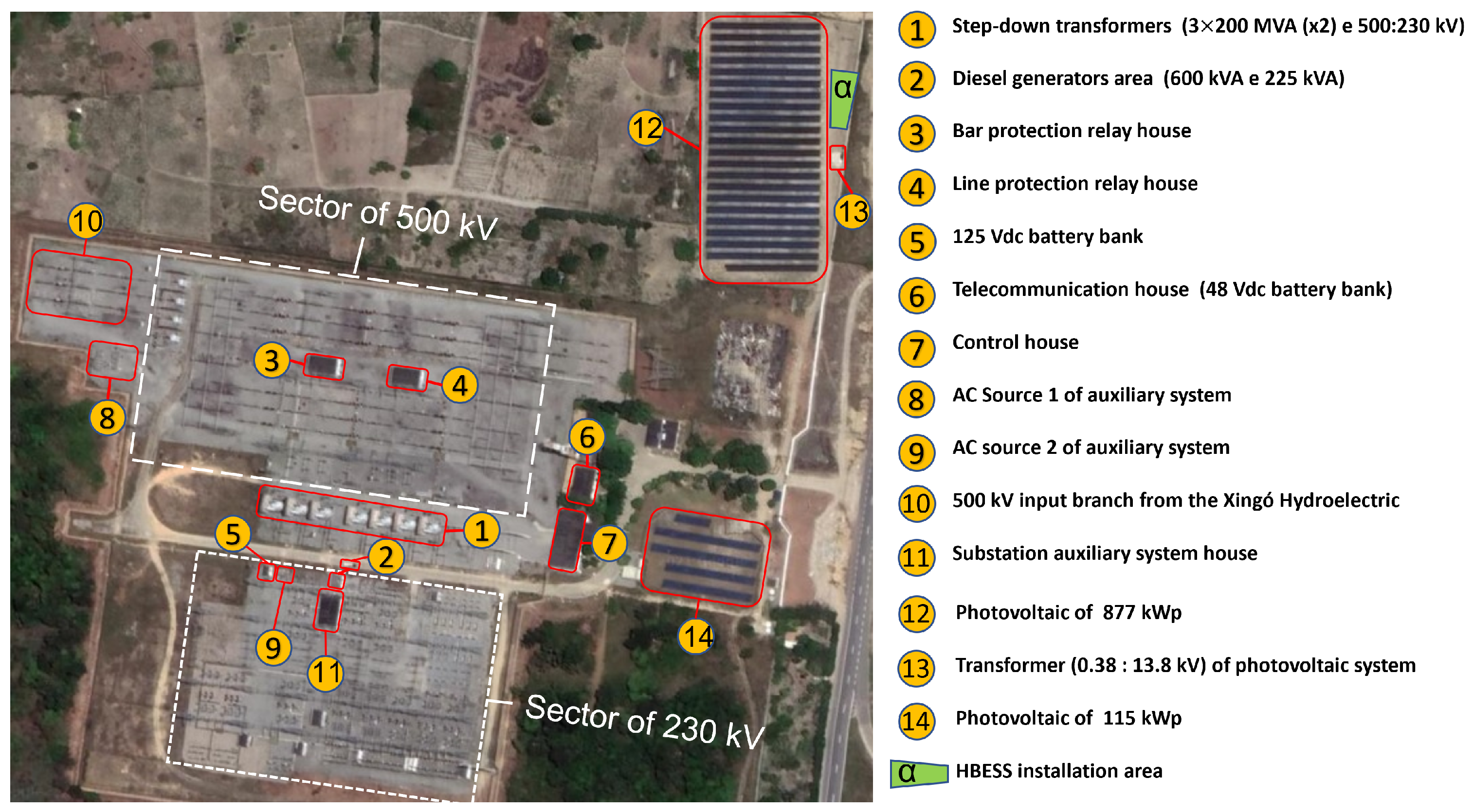
Figure 1. Real view of high voltage SS and indication of the HBESS installation location.
Energies 16 01012 g001
Figure 2. Location of the SS Messias/Chesf [4].
Energies 16 01012 g002
Figure 3. Simplified single-line diagram of the auxiliary system of Messias SS with the proposed solution.
Energies 16 01012 g003
Figure 4. Operating modes (adapted from [5]).
Energies 16 01012 g004
Figure 5. Main Scenario Offgrid (island mode).
Energies 16 01012 g005
Figure 6. Topology for Chesf microgrid validation tests.
Energies 16 01012 g006
Figure 7. Real view of the main equipment used in the tests.
Energies 16 01012 g007
Figure 8. Microgrid islanded operation.
Energies 16 01012 g008
Figure 9. Voltage and frequency of BESS 1 were collected in the power analyzer.
Energies 16 01012 g009
Figure 10. Active power of microgrid components collected by power analyzer.
Energies 16 01012 g010
Figure 11. The voltage of microgrid components focusing on diesel operation.
Energies 16 01012 g011
Figure 12. The voltage of microgrid components collected in EMS, focuses on transition operation.
Energies 16 01012 g012
Figure 13. Voltage and reactive power of BESS 1.
Energies 16 01012 g013
Figure 14. The frequency and active power of BESS 1.
Energies 16 01012 g014
Figure 15. The voltage of microgrid components, reconnection focus.
Energies 16 01012 g015
Table 1. SIN faults associated with the supply of substations’ auxiliary systems [3].
EquipmentYearShutdown (Total Amount)
SINAuxiliary Systems (AC)
Transmission/Distribution Line2017348600.00%
2018303300.00%
Transformers201782420.24%
201860130.50%
Reactive Control2017502112.19%
2018786182.29%
Converter/filters201716500.00%
201832600.00%
Buses201713200.00%
201811600.00%
Diesel Generator20172867873.03%
20182486702.82%
Total201779761001.25%
20187348911.24%
Table 2. Impact on SIN re-establishment due to auxiliary systems failures [3].
YearTime of ImpactQuantity of EventsTotal of Events
201700 h 00 min–00 h 20 min511
00 h 20 min–00 h 40 min1
00 h 40 min–00 h 60 min1
Above 60 min4
201800 h 00 min–00 h 20 min410
00 h 20 min–00 h 40 min2
00 h 40 min–00 h 60 min-
Above 60 min4
Table 3. Categories and applications of ESS technology in the electrical system.
Energy
Supplying
Ancillary
Services
Support and Infrastructure
Services for T&D
Behind-the-Meter
(BTM) Services
Renewable and
DG Integration
Time-shift;
Improving
electrical
capacity.
Voltage regulation;
Frequency regulation;
Improving
electrical reserve;
Voltage support;
Blackstart.
Investments deferrel;
Congestion relief;
Transmission support.
Energy quality;
Reliability;
Time-shift;
Demand management.
Time-shift;
Frequency regulation;
Voltagem support;
Improving electrical
capacity.
Table 4. The approximate scale between ITEMM and Messias SS microgrids.
ComponentReal ITEMM
Microgrid
Adapted ITEMM
Microgrid
Messias SS
Microgrid
Approximate Scale
BESS Pb-C250 kW100 kW300 kW1:3
BESS Li ion ¹0 kW66 kW ¹200 kW
PV Inverter252 kW36 kW100 kW (off-grid)
Diesel75 kVA75 kVA225 kVA
Load260 kW40 kW120 kW (max.)
1 BESS Li–ion is represented by BESS Pb–C in lower power.
Table 5. Simplified technical specifications of the components used in the ITEMM microgrid.
Components of the ITEMM Microgrid
BESS (Battery Energy Storage System) 1
TechnologyLead carbon
Apparent power250 kVA
Active power250 kW
Rated energy560 kWh
Rated voltage (Phase–Phase)380 V
Active power configurationpositive: discharge, negative: recharge
Reactive power configurationpositive: capacitive, negative: inductive
BESS (Battery Energy Storage System) 2
TechnologyLead-carbon
Apparent power50 kVA
Active power50 kW
Rated energy72 kWh
Rated voltage (Phase–Phase)380 V
Active power configurationpositive: discharge, negative: recharge
Reactive power configurationpositive: capacitive, negative: inductive
Diesel Generator
Apparent power75 kVA
Rated voltage (Phase–Phase)380 V
Frequency60 Hz
Full tank60 L
Photovoltaic Systems (inverters)
The rated voltage at output AC380 V
The frequency at output AC60 Hz
Maximum current at output AC53.5 A
Active power at output AC36 kW
Maximum Apparent power AC36 kVA
Resistive Load
Total rated power30 kW
Arrangement2 × 10 kW/1 × 5 kW/2 × 2 kW/1 × 1 kW
Rated voltage (Phase–Phase)380 V
Charger
Max. power per socket22 kW
Max. current per socket32 A
Electric Vehicle
TechnologyLithium ions
Total voltage400V
Energy22 kWh
Table 6. Roadmap of tests carried out on the ITEMM microgrid.
ScenarioTest
3 August 2022On-gridFunctions P–Q of BESS 1
TransitionGrid (V–f) + BESS 1 (P–Q) + BESS 2 (Load) → off-grid mode
Off-gridBESS 1 (V–f) + BESS 2 (Load) + PV 1 + “R” Load
Off-gridBESS 1 (V–f) + BESS 2 (Load) + PV 1 + PV 2 + EV + “R” Load
Off-gridBESS 1 (V–f) + BESS 2 (Load) + Diesel (20 kW) + “R” Load
ReconnectionBESS 1 (V–f) + BESS 2 (Load) → on-grid mode
Table 7. BESS 1 quality of energy in comparison with PRODIST.
Islanded 1Islanded 2Islanded 3PRODIST
Voltage (p.u.)
Maximum1.002Maximum1.004Maximum1.002Maximum1.050
Medium1.002Medium1.002Medium1.001Reference1.000
Minimum1.002Minimum0.999Minimum1.000Minimum0.920
Frequency (p.u.)
Maximum1.000Maximum1.000Maximum1.000Maximum1.002
Medium1.000Medium1.000Medium1.000Reference1.000
Minimum1.000Minimum1.000Minimum1.000Minimum0.998
Disclaimer/Publisher’s Note: The statements, opinions and data contained in all publications are solely those of the individual author(s) and contributor(s) and not of MDPI and/or the editor(s). MDPI and/or the editor(s) disclaim responsibility for any injury to people or property resulting from any ideas, methods, instructions or products referred to in the content.