1. Introduction
To date, modern ships are, in essence, large energy systems having an intricate interaction among their components. Simulating the behavior of complex systems represents a certain art. A mathematical description of a rather complex system, which is a modern ship, does not allow for implementing the ship model in general. The totality of mechanisms, machines, energy sources, heat exchangers, pipelines, and electrical subsystems designed to organize the possibility of ship movement and the transfer of various types of energy to its various consumers is a shipboard power plant. The power plant includes a main power plant, which drives the ship, consisting of the main engine, a ship propulsion, an electric generator, and a shaft line. There are a number of individual energy models, each of which provide a solution to a well-defined range of specific questions concerning the system’s behavior. At the same time, each of the models has its own mathematical structure, characteristic mathematical properties, and is suitable for studying a certain class of problems related to the system’s functioning. Since all these models form a single system (ship), they are interdependent. The operating modes of some systems influence others. However, at the same time, the work of all the systems should be aimed at performing the main functions of the ship. Therefore, the task of combining all the disparate models of the ship systems within a single model is extremely relevant. The solution to this problem is possible using different types of mathematical description [
1].
At present, the need for creating complex mathematical models is steadily growing. Complex simulation represents a complex interdisciplinary analysis and an interaction of design stages that requires new approaches and design tools.
From the viewpoint of a unified position, the full coverage and the simulation of all the ship systems are rather a difficult and, generally speaking, currently unrealizable task. At the same time, considering some systems separately, as well as many separate systems along with the interaction occurring between the parts, implements the so-called integrated approach to simulation. For instance, the mathematical simulation of the processes proceeding in the ship’s electrical power and the mechanical system is of major importance in solving the tasks of designing new types of ships, research, management, and reliability assessment.
The multiple connectivity and complexity of such systems complicate the approach to complex simulation. This fact is explained by the difference and the diversity of the physical processes and the mathematical description complexity of these processes.
The modern literature reflects a number of studies conducted in each local area that are of interest when constructing such a large system.
The works [
2,
3] demonstrate the use of new methods intended for controlling the ship’s power consumption, including the hybrid methods based on neuro-fuzzy systems, namely on the ANFIS model. The authors show that the transition to a flexible intelligent system, in comparison with classical control modeling methods, has a greater economic effect, reducing harmful emissions (if a similar approach is applied to fuel systems).
The connection between the input and output parameters of the simulation can be of a reverse nature in the “design-construction-repair” chain. The issues of structural analysis of the shaft line constructions allow for optimizing the construction at the stage of the ship project in terms of vibration problems. The propeller shaft system experiences a complex nature of periodic loadings. For example, the authors in [
4,
5] use the finite element modal analysis to determine the range of forbidden frequencies of the main engine and to build an optimal scheme for installing bearings. The work [
6] presents the results of studying an analytical model of axial vibrations of the shaft line that helps to improve the design of ship vibration isolators.
The creation of a digital twin of mechanical power systems should fully cover all the stages. The results of simulating the behavior scenario of an object of a ship’s electric power system (SEPS) are embedded in the process of managing and training the specialists [
7,
8,
9]. The methods used for accelerating the modeling of the onboard simulation processes of a ship’s electric power system using multicore computing are described in [
10]. Approaches to improving the performance of software and hardware methods are presented in [
11,
12].
The geometric simulation followed by the finite element analysis and the introduction of CAD tools significantly optimizes the design activity [
13].
The research [
14] demonstrates using a finite element model of a synchronous generator to simulate and identify a transient process, spectral analysis of the ship network, defects (identifying the current and voltage spectrum of the faulty generator), and a variant of arranging the diagnostics system of the ship’s electric machines.
In the case of complex systems, the application of intelligent systems accompanied by reinforcing learning is effective as shown in [
15]. When the model-free control is used (for example, the ship power supply), the constant replenishment of the knowledge about the object allows for predicting and managing under conditions of uncertainty and increasing the safety level [
16,
17].
The similar diagnostic models of the state of an internal combustion engine that were constructed using neural networks (for example, those mentioned in [
18]) can also be used for the ship systems supplemented with approximation dependencies relating to the wear of the piston rings to operating modes.
An analytical assessment of the functioning reliability of the heat engines is hindered due to the difficulty in finding a function that correlates the wear of engine elements with the operating modes [
19], unlike, for example, turbo engines.
In addition, the intelligent models that work with a database of the current modes and equipment operation models, so-called digital twins, complex models that display the relationship of the model with real operating conditions, are very relevant [
20,
21,
22].
In [
23,
24,
25], the operation reliability of the systems is increased owing to use of intelligent models based on the digital twins. Reliability is enhanced by the introduction of a self-diagnosis system that compares the real and generated data. This approach is being investigated by the example of the engines, bearing systems, batteries, etc. Processing the signals of various individual systems of the ship is quite a difficult task. The combination of a complex structure and a nonstationary operating mode makes the measured signal of the machine multicomponent have a complex, time-varying spectral structure. In this paper, we propose an implementation of the analysis method based on adaptive synchronous demodulation transform (ASDP). The analysis is performed by searching and constructing the demodulation term element based on the analysis of target signals of spectral data [
26]. The overall goal is to efficiently analyze the frequency–time characteristics of the target signals. Using adaptive synchronous demodulation and continuous wavelet transform, the method aims to capture the time-varying frequency components of the signal. A three-dimensional matrix facilitates the visualization and interpretation of the time–frequency information [
27].
In general, it is worth noting that the tasks of modeling various systems of ships and the movement of the ships themselves [
28] are quite numerous, complex, and very heterogeneous.
The general disadvantages of the mentioned literature sources are as follows. The first is that the analytical approaches are used to simplify the analysis, but the applicability of such approaches is questionable. The second is the fact that the presented models are local in nature and they describe particular physical processes. The third is an issue that there is no attempt in combining the models into a multiple-model structure.
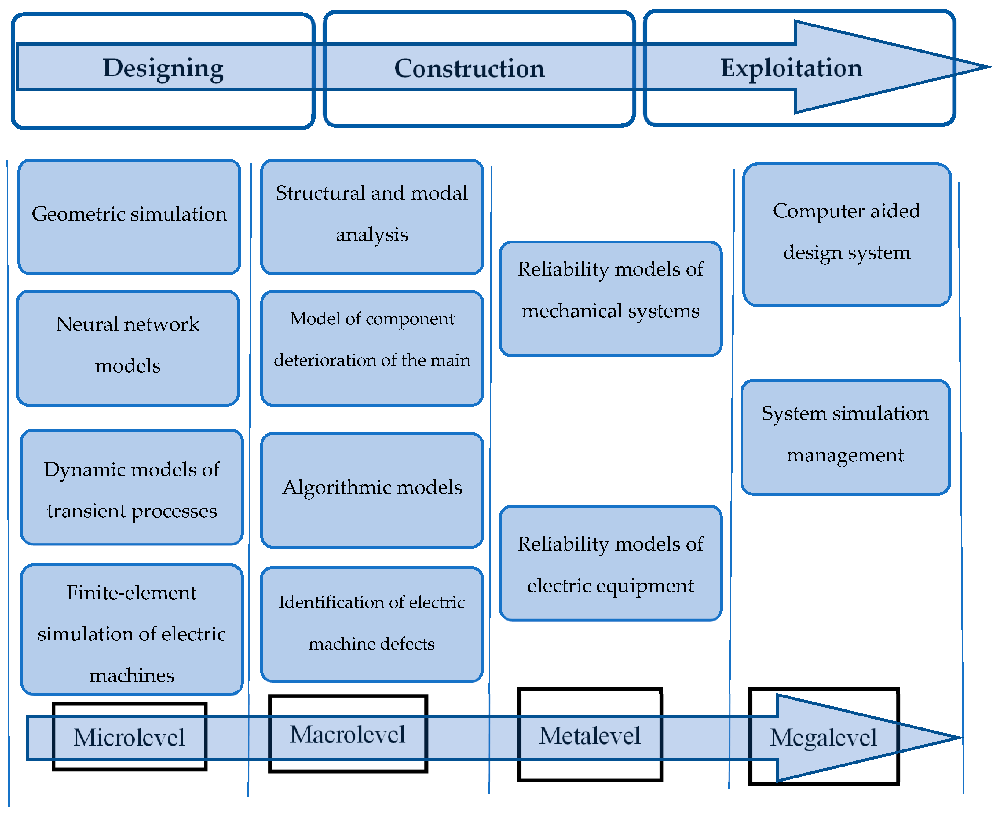
Combining the multiple-model complexes to include the above models necessitates understanding the mathematical description of a particular object and can be approximated by a formal model. The model structure of the object or level can be formalized and generated in the desired way in accordance with the modeling problems (research, optimization, or management) [
29]. The development of the structures similar to that shown in
Figure 1 should be noted to illustrate the complex process of a multi-criterion selection, which requires a constant coordination of the structure levels and a heterogeneous representation of the objects of the ship system.
An analysis of the literature shows that to date there is no single model connecting the following ship systems:
Mechanical system of power plants (propeller shafting);
Regression experimental models of wear of main engine elements;
Diagnostic models of the state of the electrical equipment (synchronous generator);
Models used for controlling the electric power system;
Algorithmic models used for controlling the main distribution board of a ship.
In this regard, the objective of this study is to develop a methodology for simulating a complex single ship model, which includes a set of subsystems of various levels (microlevel, macrolevel, metalevel, megalevel). The paper shows how it is possible, using the developed approach, to create a digital twin of a ship as a large unified system, rather than a set of separate models. Such a complex model is constructed by the example of the relationship established among mechanical, electric power, algorithmic models and the control model. To achieve the purpose in view, the following tasks must be solved:
To develop local mathematical models of various mathematic levels:
Model of the stress–strain state of the propeller shafting and natural frequencies;
Model of the wear of piston rings in the main engine;
Models of the transient process occurring in the electric motor;
Model of the electromagnetic processes of a synchronous generator, as well as the identification of defects;
Model of controlling the main distribution board.
To determine the relationship between modeling levels and service life stages, a unified model of the interaction occurring among the ship systems should be built.
In this study, an approach is proposed that connects the models of the elements of the ship’s electric power system with the functional capabilities. Below, the work presents in detail the experience of simulating various ship systems and a mathematical model allowing the combining of the models into one large system.
The main task of the scientific work was to develop a set of mathematical models combined into a system capable of describing in aggregate the electrical and mechanical processes proceeding on a ship of various modes. The paper presents the newly developed, complex, polymodel approach to modeling a ship as a simulation system. The general polymodel approach to the description of a ship as a large system allows for presenting the mathematical models of the objects, the processes, and the dynamics of the system as a whole from a common viewpoint. The partial verification was carried out for the following models: the shafting, generator, the ring wear of the container ship COSCO Long Beach (IMO 9285677) built by HHI in 2004. It should be noted that the ring wear model was originally built using the experimental data obtained from the real ship.
2. Materials and Methods
Technological objects may demonstrate different properties in different situations, and may not have adequate models in terms of classical differential equations. The objects can have a continuously discrete behavior, containing stochastic constituents in the varying parameters. Neglecting these facts does not facilitate the construction of adequate analytical models of the objects.
Simulation modeling provides a mathematical apparatus (a formalized scheme) that generates the desired structure of the object model that meets the purposes of the study, filling this structure with quantitative relationships that describe the relationships among its elements, thus solving various problems of the analysis and selection. The creation of SM, as well as simulation models (simulation-level models), is a complex multi-stage iterative process, whose main peculiarity (as compared to “purely” simulation modeling) consists in the necessity to coordinate different models describing different aspects of the object functioning at each of the research stages (at the conceptual, algorithmic, informational, and software levels).
This work shows a methodological approach to a complex simulation of complex systems and presents the experience of using a wide class of methods and tools intended for simulating elements, the electric power, and the mechanical systems of a ship. Heterogeneous models are related through the apparatus of the set theory. The elements of the corresponding sets (models) and the relations connecting them are determined by the specifics of the system. Such a description of the system allows for an analysis of the structure of the system and its behavior. Various systems containing heterogeneous constituent elements can be investigated by means of this methodology.
The simulation objects in this work are:
Mechanical systems (a built-up construction of the propeller shaft line consisting of bearings and a system of propeller shafts having a flange connection);
Process of wear of the piston rings of a diesel engine;
Dynamic processes occurring in a synchronous generator;
Current and voltage spectra of a synchronous generator with and without a defect;
Rules and algorithms of the functioning of the main distribution board of the ship: diesel generators, electrical networks, consumers;
Short circuit processes proceeding in electrical machines, emergency modes.
These models generally reflect the ship behavior as a large multivariable system.
Different approaches are used to develop local mathematical models depending on the model specifics. The simulation itself is performed using specific software suites and tools of these suites. These models are combined into one system by means of a set-theoretical approach. A mathematical description of each of the models, including a description of the dynamics of each of the systems, is provided in the framework of the approach. In this case, the output parameters of one model are the input parameters of the other.
2.1. The Theoretical-Set Description of the System
A wide range of the objects at various simulation levels was used in these studies:
Simulation microlevel:
Three-dimensional geometric models of the elements of the propeller shafting and the generator;
Forms and frequencies of natural vibrations of mechanical systems;
Stress–strain state of the elements of the propeller shafting system;
Static and dynamic electromagnetic processes occurring in a synchronous generator.
Simulation macrolevel:
Simulation metalevel:
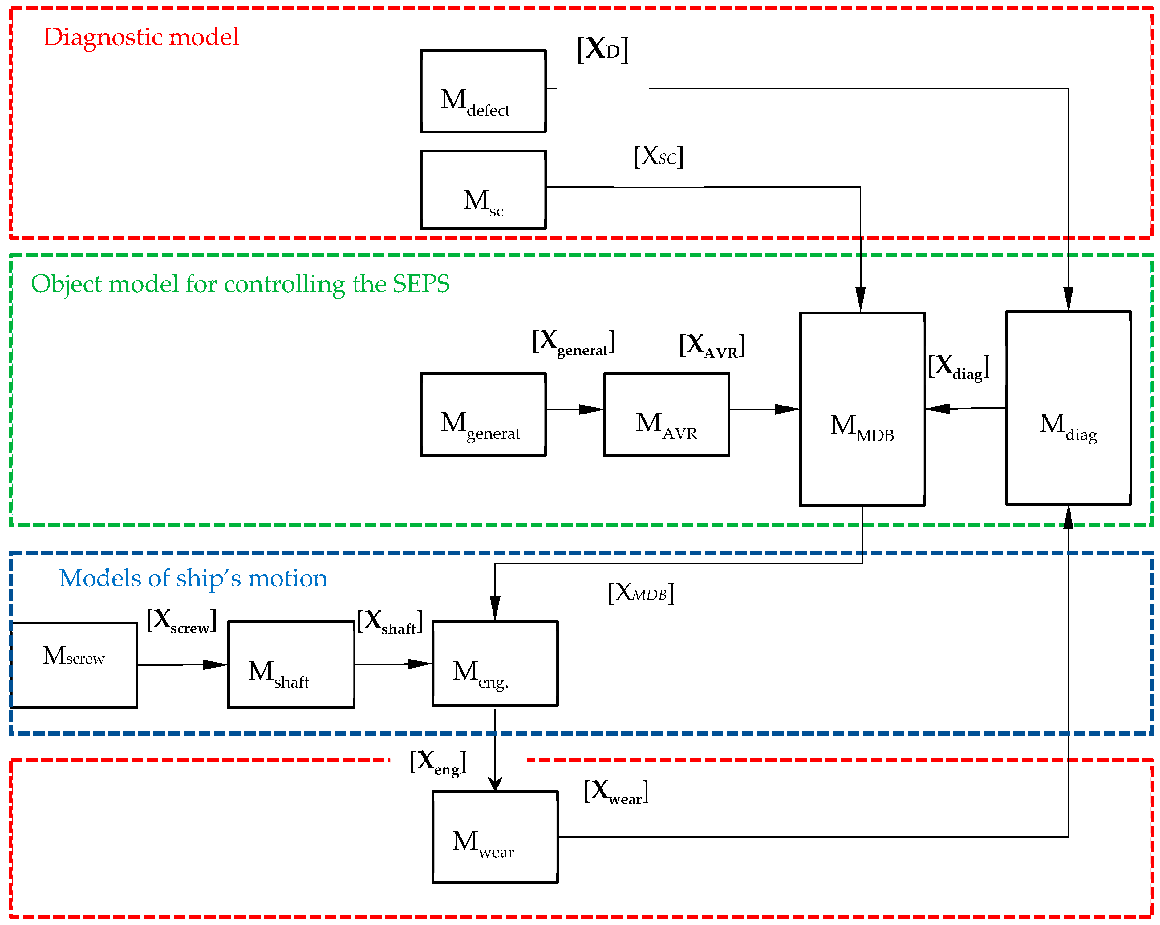
The local models presented in the study are combined into one set-theoretical model. The scheme of connecting various systems and their interaction is shown in
Figure 2. The purpose of this scheme is to show the mechanisms of the interaction occurring among the models of various levels (microlevel, macrolevel, metalevel, megalevel).
The following notations are provided in the figure:
—state vector of the parameters of the synchronous generator model having a mechanical defect: phase currents, phase voltages, and spectral frequency;
—vector of the parameters of the synchronous generator having a short circuit: phase currents, voltages, and spectral frequency;
—vector of synchronous generator parameters: current, voltage, power, and speed;
—vector of the parameters of the synchronous generator voltage regulator: exciter current and generator voltage;
—vector of internal combustion engine parameters: instantaneous power and consumption;
—vector of the parameters for diagnostic algorithms: frequencies, currents, and voltages associated with a mechanical and electrical defect of the synchronous generator;
—wear values of the different rings of the engine cylinders;
—vector of the parameters of stresses, displacements, and natural frequencies of the propeller shaft system;
—vector of values of the torques of external forces caused by the propeller screw: reversible, dynamic, and static torques.
An example of calculating the parameters of these vectors is shown in
Section 3 of this work.
The constructed model represents a deterministic, nonlinear, nonstationary, finite-dimensional, differential, dynamic system. The figure shows the relationship of the models
Mdefect,
Msc,
Mgenerat,
MAVR,
MMDB,
Mdiag,
Mscrew,
Mshaft,
Meng,
Mwear, which are part of the generalized model (
Figure 1).
The set theory allows for operating with mathematical abstractions and the relationships between their elements. The elements of the corresponding sets and the relations connecting them are determined by the system specifics. There are two sets X, Y, whose elements are associated with the ship. The relationship between the sets is described using binary relations, which are represented by the matrix of incidents (1). From a geometric point of view, the relations define a simplified complex scenario where the elements of the Y set are considered as vertices, and the elements of the X set are simplexes. Therefore, the Y1 element (generator) is a 0-simplex consisting of the X4 vertex (wear).
Let the system Σ (ship) contain a set of the investigated objects Y and a set of the states X, where:
Y = {generator, shaft, rings, main distribution board (MDB)},
X = {shaft eccentricity, turn-to-turn fault, modes, harmonics, wear}.
The studied states are the values of the parameters of various ship systems (resonant shaft frequencies, the generator operation frequency, etc.). The incidence matrix (1) shows whether or not there is a relationship between these objects and their states, where 1—there is a connection, 0—there is no connection.
Having an incident matrix
such that
, where
. In this case:
The set theory provides an opportunity to operate with mathematical abstractions and relations between their elements. The elements of the corresponding sets and the relations connecting them are determined by the system specifics. There are two X and Y sets, whose elements are related to the ship. The connection between the sets is described by means of binary relations, which are represented by the matrix of incidents (1). Geometrically, the relations define a simplistic complex in which the elements of the Y set are treated as vertices and the elements of the X set are simplexes. In view of this, the element Y1 (generator) is a 0-simplex consisting of the vertex X4 (wear and tear). The system dynamics is described by the notion of the image ∏. The image ∏ is a mapping, which attributes a certain number to each simplex, for example, the wear value of the engine rings (). Since each simplex has a geometric dimension, the image ∏ is a ranked image (2), i.e., the sum of images .
A complete graded pattern ∏ of this system has the form:
where:
The system dynamics will be described as a change in the ∏ image at each moment of time [
30]. For this system, these changes will be forces acting on the fixed geometry of the complex, specified by certain models.
These models can be classified by the simulating type and by hierarchy. That is, the models can be attributed to certain micro, macro, and metalevels. A complex approach is presented to solve the set tasks. These tasks are solved by means of a multicomponent model complex, which includes blocks containing incoming model classes.
2.2. The Mathematical Description of the Models
The mathematical description of the models
is internal and can be presented in the general case by a differential equation of the form:
where
is a vector, characterizing the state of motion of the elements;
,
are known vector functions through which the restrictions to the motion process of the objects and boundary conditions are set. At the same time, the dynamics of the system
are set in various forms.
Equation (3) describes the dynamics of the models, which are generally represented by a differential equation. In the equation, the derivatives of the state of the element are on the left side, and the applied load is on the right. For example, the deformation rate of the shaft depends on the applied force load.
The mathematical description of the model
is external and can be presented in the form of the generalized mathematical model of the processes of controlling the MDB functioning:
where
are the generalized vectors of the state and control of MDB;
are known vector functions, through which the boundary conditions for the vector
are set at time points
;
are vector functions, setting the main space–time, technical, and technological constraints imposed on the functioning process.
Equation (4) represents the control models. In such models, the state of the model elements depends, in addition to the power component, also on the control action. Such models include, for example, the generator controller model.
Therefore, each model has a vector of input and output parameters. The input and output parameters depend on what model type the system is described as a whole. The dynamic models are described by the equations of type (3); the control models are described by the equations of type (4).
As a result, Equation (3) describes the dynamics of the models, which are generally represented by a differential equation. In the equation on its left side, there are derivatives from the state of the element, and the applied load is on the right side. For example, the shaft deformation speed depends on the attached power load.
Equation (4) is a control model. In such models, the state of the model elements depends, except for the power component, also on the controlling exposure. Such models include, for example, the generator regulator model.
In each specified case, for the given objects of the equation, a specific type (for example, Equations (5) and (6)) will describe the dynamics of the generator and the gross. In this work, obtaining optimal management was not a goal. Optimal management is the next stage in the development of this approach.
3. Results
This section presents the results of simulating the various elements of a ship, whose dynamics is described mainly by the equations of the form (2) and (3), considering the specifics of simulating each element. Specific mathematical formulations are provided for each of the considered elements of the system.
The simulation was performed for a ship of the transport fleet such as a tanker. This ship is a system that moves mechanically, whose synchronous generator is the main one. The simulated ship has the main ship low-speed dual-fuel diesel engine manufactured by Hyundai Heavy Industries (Ulsan, Republic of Korea) under a license granted by MAN Energy Solution (COSCO Long Beach (IMO 9285677).
3.1. The Development of a General Scheme of the Interaction among the Models of Various Ship Systems
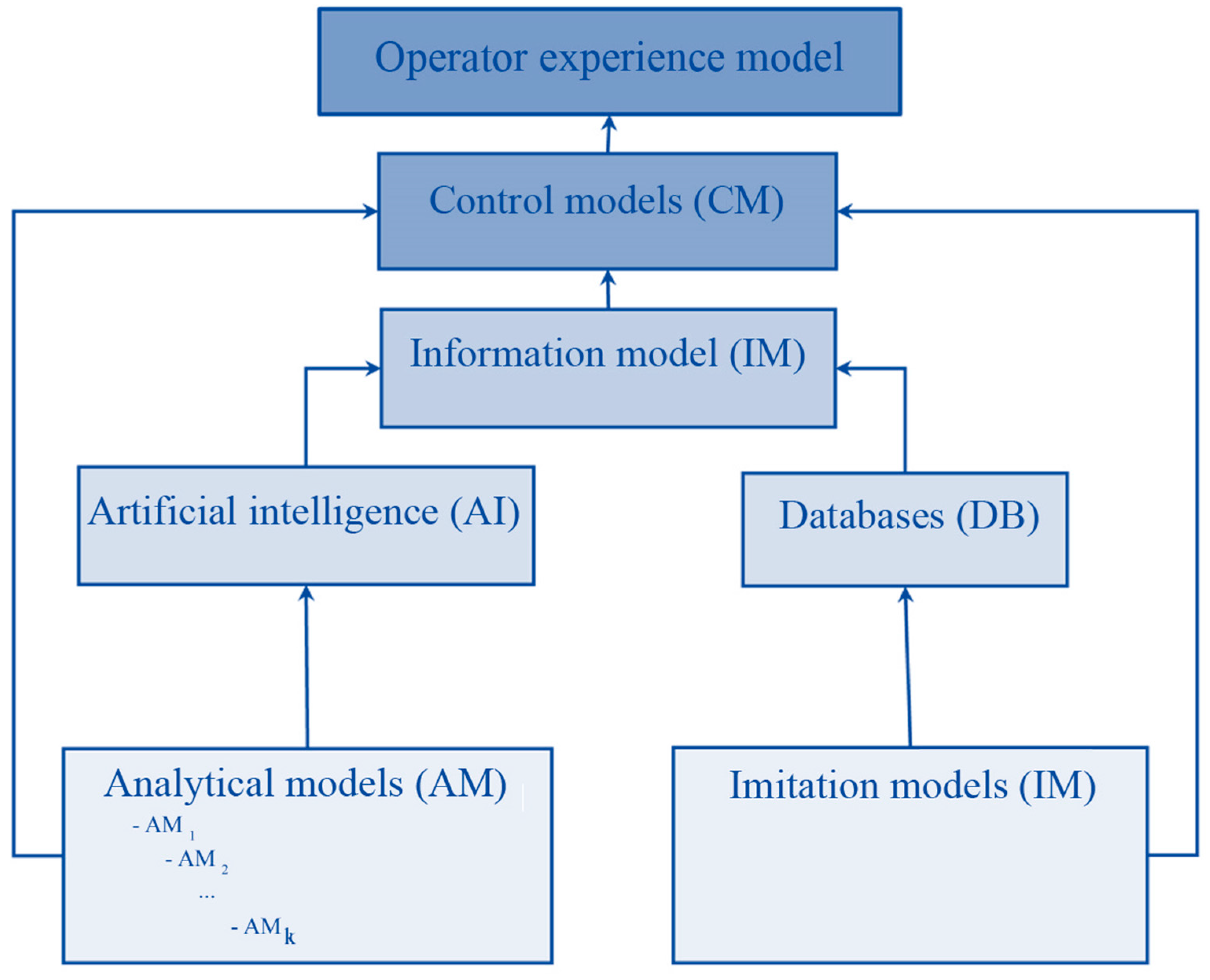
A complex model of a ship as an energy-mechanical object can be obtained by combining analytical, simulation, logical, and algorithmic models, and it represents a simulation system (SS). Combining the isolated models of individual ship nodes facilitates solving the problem of forming a single model of the functioning of all the ship’s systems. This enables performing the basic functions of the ship without failures of individual systems and minimizing emergency situations. In fact, a digital twin of the ship is being built. The block diagram of such a model is shown in
Figure 2 [
1]. The diagram shows the interaction of different models. At the same time, let us take into account the fact that different models may have different variants of the used solutions (using databases, artificial intelligence). These models transmit data and form a digital twin of the ship (IM). Then, all the necessary parameters of the general condition of the ship are transmitted to the control model (CM). The control model generates the required control actions to achieve the required condition of the ship. It transmits these actions to the ship system controls and to the ship captain. At the same time, the control model (CM) obtains data not only from the ship digital twin (IM), but also directly from low-level models (AM, IM). Examples of the application of this approach to solving particular problems are provided in [
13,
31,
32].
The studies of the local structures and the objects of the ship’s electric power system discussed below are still of private nature and describe the physical processes proceeding in the system elements, but can and should be combined into a multiple-model structure as shown in
Figure 1.
The simulation system can be generally represented in the form of a specially organized simulation complex consisting of the following elements. The first one refers to the structure of simulation models in its object domain. The second represents the structure of analytical models that provide an accounting of the parameters of modeled objects. The third is a subsystem representing information technology based on a knowledge base, algorithms, and competencies. It is based on expert systems and machine learning. The fourth one is based on the control system and control signal transmission system, which connects all parts of the system and organizes the user interface and dialog with the system operators.
The simulation experience shows that the focused specialization of SS is weakly amenable to the universalization requirements.
At the same time, the hierarchical models are divided into the following levels: a microlevel, a macrolevel, a metalevel, and a megalevel. The connection of the levels and the transition among them are arranged according to certain rules and patterns. Each of the levels has its own solutions concerning the simulation and management of the objects (
Figure 3). The microlevel combines the analytical models (AM) shown in
Figure 2. An example of such models is the equation of the propeller shaft vibrations, the wear model of the engine piston rings, etc. The macrolevel is simulation models (SM). An example of such models is a generator operation model, a modal analysis of a shaft line accompanied by the determination of natural oscillation frequencies, etc. The metalevel is a control system model (CM); it includes a generator controller model, a voltage regulator model, etc. The megalevel is the termination model that determines the control of the entire system as a whole. This is a simulator model of the main distribution board. More examples of ship systems related to these levels can be found in [
13,
31,
32].
The design, construction, and operation of the ship are directly related to solving the problem of providing connections and transitions between these levels. Arranging such an interaction represents a difficult task. The labor costs and ship building expenditures will depend on the accuracy of solving this problem. In addition, the interaction between these systems will determine the entire subsequent service life of the ship.
3.2. Simulating the Synchronous Generator Operation and the Frequency Spectrum of a Faulty Generator
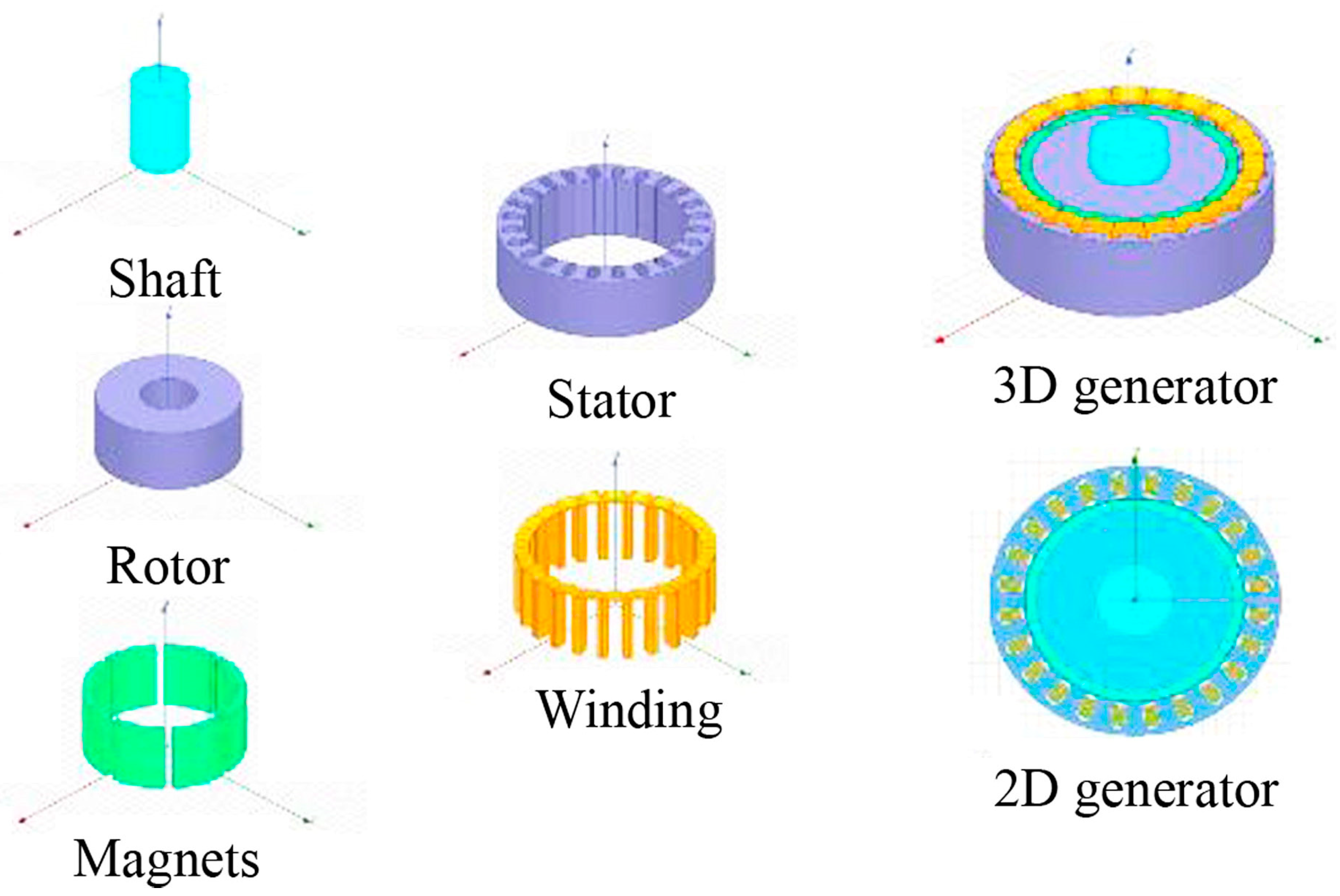
A ship synchronous generator having an internal diameter D = 1.616 m of the stator was chosen as the generator model. The geometric and mechanical parameters, as well as a method for constructing a generator model, are described in [
33]. The start-up of the synchronous generator followed by reaching a steady-state operation mode at a rotor rotation speed of 625 rpm was simulated. The constituent elements of the generator are shown in
Figure 4.
The processes occurring in the system are mathematically described using an equation of type (2). The electromagnetic fields created by the electric machine are described using Maxwell’s equations:
where
—curl operator;
—divergence operator;
—magnetic field intensity vector;
—total current density vector;
—applied source current density vector;
—induced eddy current density vector;
—velocity current density vector;
—electric flux density vector;
—time;
—electric field intensity vector;
—magnetic flux density vector;
—electric charge density.
Equation (5) (Maxwell’s equations) describe the dynamics of the electromagnetic field and its relationship with electric charges and currents in continuous media.
The relationship between the values of the strengths and inductions of magnetic and electric fields on different surfaces is set as boundary conditions.
Equation (5) (Maxwell’s equations) describes the dynamics of the electromagnetic field and its connection with electric charges and currents in solid media. Equation (5) can be solved by the numerical method. In this study, an ANSYS 2020 R2 package was used for a numerical solution of Maxwell’s equation, which uses the numerical projection and sampling methods, including the finite elements method as a modification of the rittz and gallerykin methods.
The method of simulating various defects of the electrical machines based on their numerical models is very efficient [
34,
35,
36,
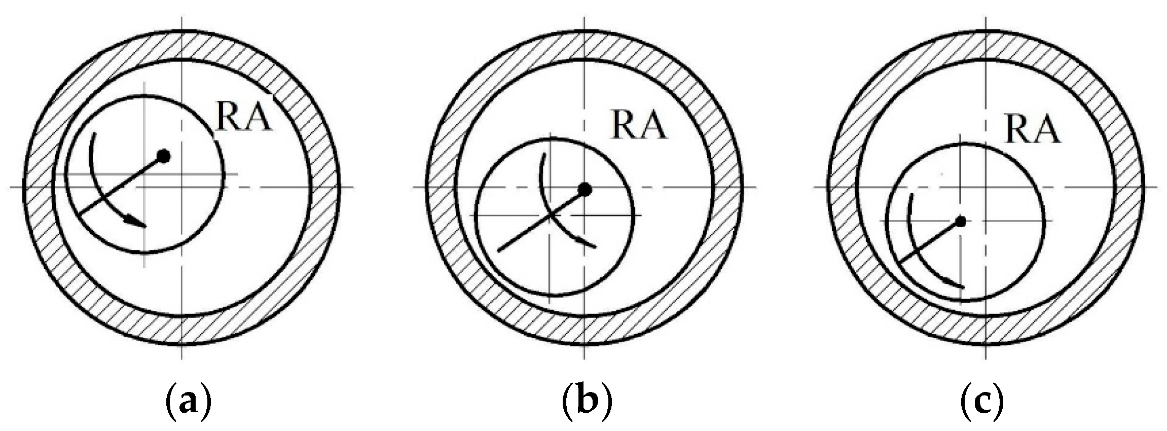
37]. The numerical value of the air gap between the rotor and stator in electric generators and motors determines the magnetic and electrical loads. The influence of the model effect (rotor eccentricity) on the network quality is investigated. The following types of rotor eccentricity are modeled (
Figure 5).
Type A: This variant is a blend, where the rotor’s rotation axis, RA, does not align with either the stator’s axis of symmetry or its inherent symmetry axis. Type B: Defined as dynamic, the rotor’s rotation axis, RA, aligns with the stator’s axis of symmetry but not with its inherent symmetry axis. Type C: Described as static, it occurs when the rotor’s rotation axis, RA, aligns with its own symmetry axis and does not align with the stator’s axis of symmetry.
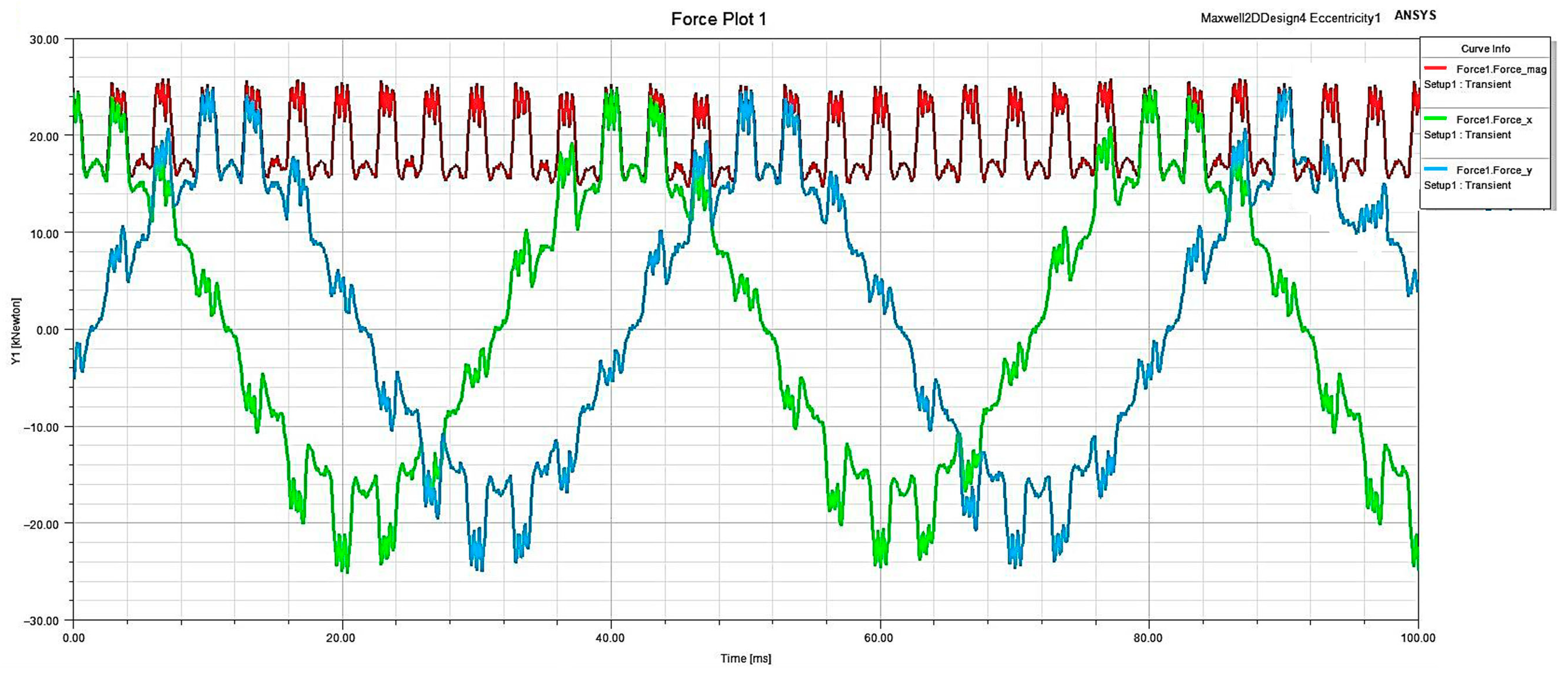
The evaluation of the impact of generator eccentricity can be conducted by examining the force components diagram, as illustrated in
Figure 6. This graphical representation encapsulates the entirety of internal forces exerted on the components in rotation. In instances where the rotor is balanced, the radial component of these internal forces is effectively counteracted. Conversely, the tangential component of these internal forces gives rise to torque. Broadly speaking, this constitutes a volumetric force acting upon the rotor. Nevertheless, when the configuration is balanced, this force is commonly overlooked.
The rotor torque value is preferable to it.
The analysis of the frequency characteristics of force vector components, specifically Fx and Fy, reveals notable patterns when examining the presence of rotor eccentricity and its absence or lack of defects. In instances where rotor eccentricity is present, there is a discernible emergence of a harmonic component within the force spectrum. This harmonic component exhibits a substantial amplitude, with its peak value occurring at a lower frequency range.
It is imperative to note that these investigations were conducted through simulation on a synchronous brushless generator. The simulation outputs comprise detailed time oscillograms illustrating the behavior of key parameters such as flux linkage, phase currents, and voltages, as well as forces and torques. This comprehensive analysis provides insights into the dynamic interactions within the generator system, shedding light on the influence of rotor eccentricity on the force vector components and their associated frequencies. The frequency characteristics of the specified generator in idle modes were obtained based on them.
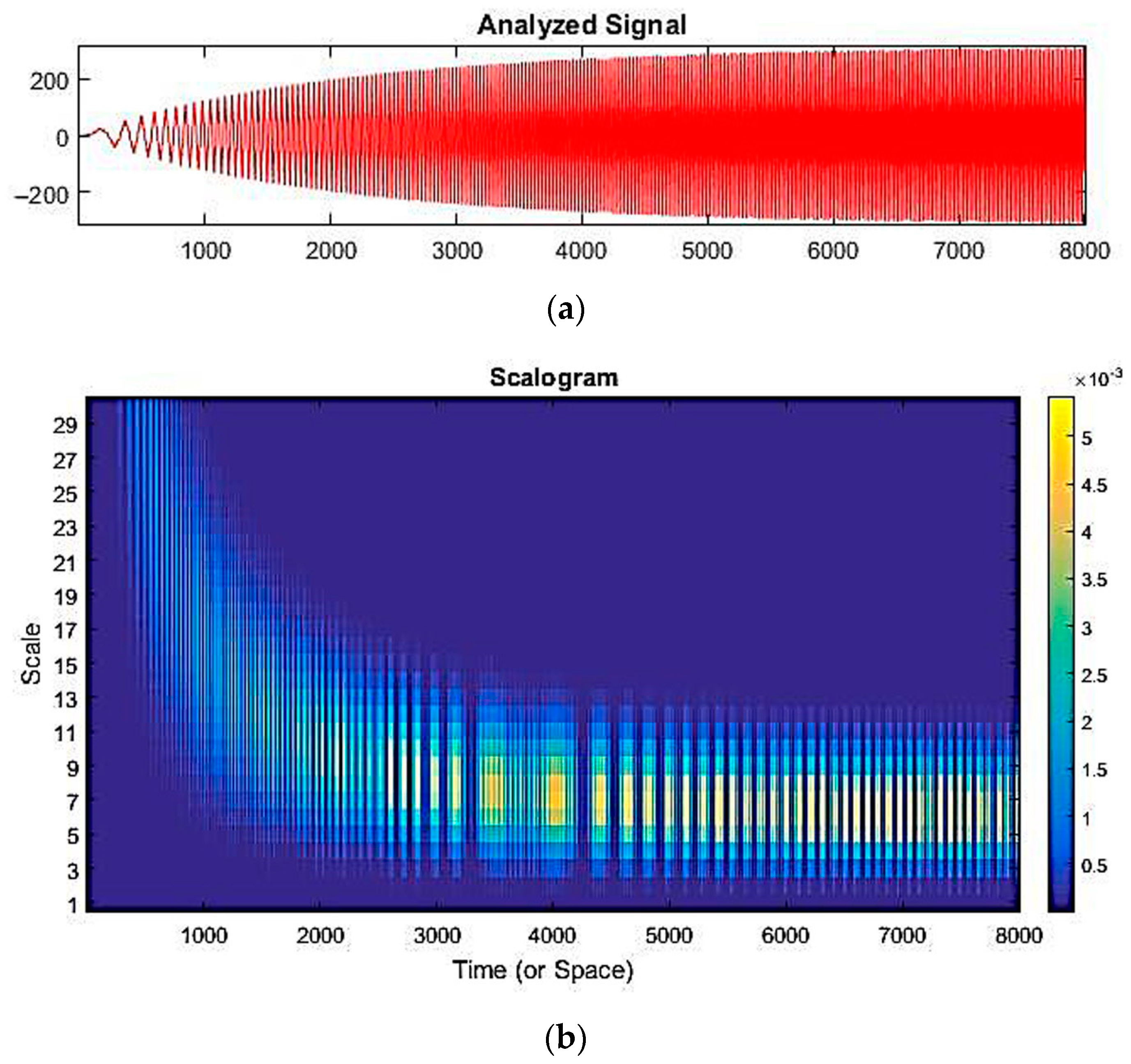
The results of simulating the start-up of the generator and reaching the stationary mode are shown in
Figure 7a by the example of changes occurring in phase voltages. The time-and-frequency analysis of the signal was performed using the wavelet transform (
Figure 7). The illuminated regions in the wavelet transform coefficients Ca,b, as illustrated in
Figure 7b, provide insights into the augmentation of rotor rotation speed. Examination of these coefficients reveals the existence of three distinct frequency domains: the domain associated with the acceleration of speed, the phase leading to the critical speed, and the stable, steady-state mode. A crucial observation is that the intensity of the light areas in the scalogram, corresponding to higher wavelet transform coefficients, directly correlates with the magnitude of energy encapsulated within the frequency component of the series. In essence, the more pronounced the illumination in the scalogram, the greater the energy content of the corresponding frequency component.
This numerical modeling approach provides the ability to identify spectra of voltages, currents, forces, and moments corresponding to both mechanical and electromagnetic defects. Importantly, this model is able to accurately diagnose generator defects caused by rotor eccentricity, even under start-up conditions and in initial operating modes.
With a deeper look at the numerical model, we are able to identify and analyze the spectra of voltages, currents, forces, and moments associated with possible mechanical and electromagnetic faults. This approach allows for predicting and detecting even the smallest deviations associated with generator defects, which makes it unique in the aspect of pre-diagnosis already at the start-up phase and in the initial modes of operation.
Thus, the numerical model provides a high degree of accuracy and sensitivity in detecting rotor-eccentricity-related faults, making it an effective tool for the early diagnosis and prevention of potential generator problems.
3.3. Simulating the Stress–Strain State of the Propeller Shafting and Studying Its Dynamics at the Design Stage
At the design stage, it is important to know the natural resonant frequencies to develop effective design solutions, as well as the purpose of the operating ranges of the main engine [
38]. Abnormal vibrations can cause element failures. The task of studying the state and the behavior of composite propulsion plants, where a complex process of interconnected torsional, longitudinal, and transverse vibrations takes place, can be divided into a number of composite problems of statics and dynamics.
In this work, the stress–strain state is calculated and a modal analysis of the constructions is performed using the finite element simulation in the ANSYS environment.
When considering the majority of structural dynamics problems of mechanical systems, the application of spatial discretization using the finite element method allows us to obtain a semi-discrete finite element equation of motion based on the principle of virtual work, and it is as follows:
where
—structural mass matrix;
—nodal acceleration vector;
—structural damping matrix;
—nodal velocity vector;
—internal load vector;
—applied load vector.
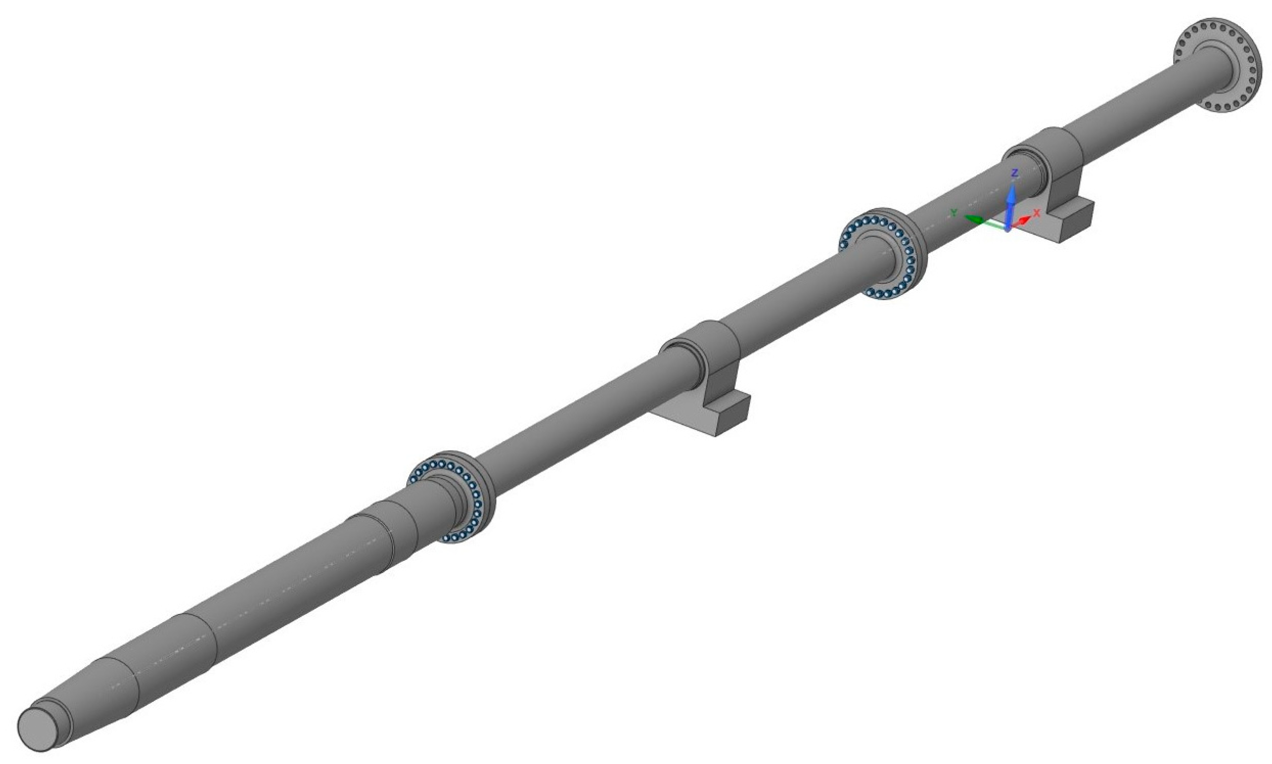
Based on the three-dimensional model of the gross, the finish-element grid was created containing 31,045 nodes. The dynamics of such a system is described by Equation (6). The solution of this equation enables finding the displacement, speed, and acceleration for each node. The solution is revealed using numerical modeling in the ANSYS system. The computing environment implies an ANSYS package.
Equation (6) describes the movement dynamics of the shaft points during the finite element discretization of the shaft line. The system geometry consists of a thrust shaft, intermediate shaft, and propeller shaft (
Figure 8). The model parameters are given in
Table 1. The shaft line of the ships of the R-1706 series (Samotlor-type tankers) with a diameter of 0.695 m was chosen as a calculation model.
Based on the three-dimensional model, a finite element mesh of the tetrahedral elements was created, having a maximum size of 200 mm, where the number of nodes was 31,045 and the number of elements was 17,839. Bearings set the following boundary conditions: the restriction of movements in a plane perpendicular to the shaft. Bolted connections were “rigid restraints”.
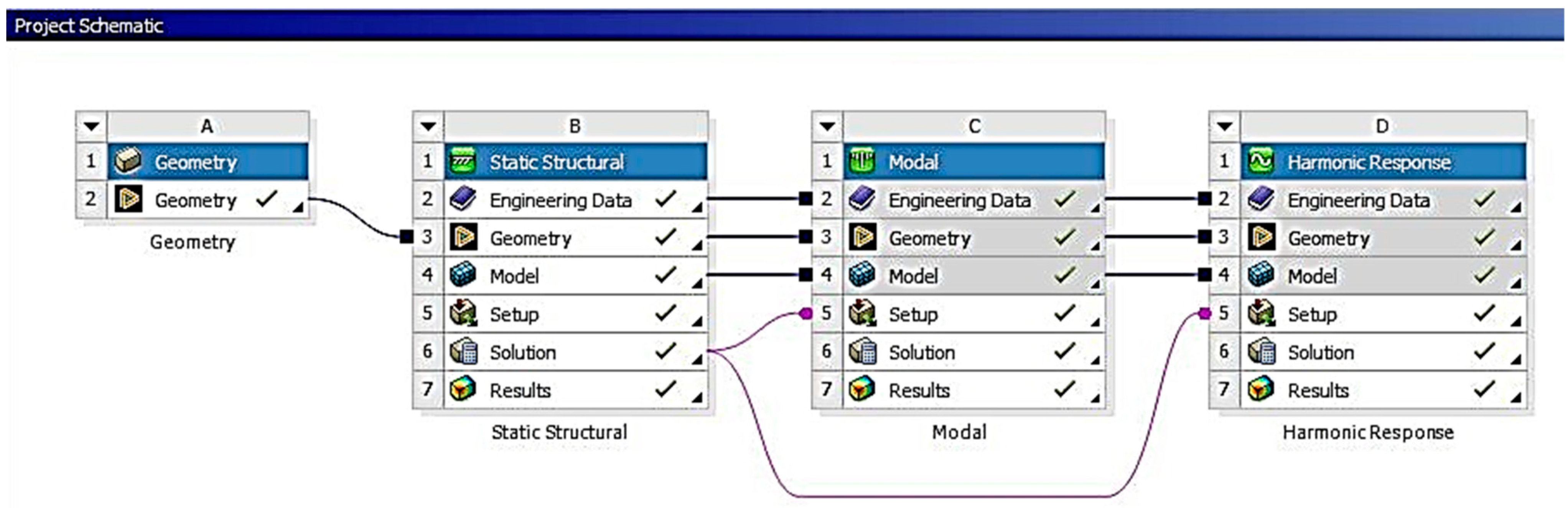
The calculation involves solving three problems, which represent statical, modal, and harmonic analyses (
Figure 9).
The geometric and finite element simulation enables the design calculation and a technology design for other ship elements and constructions [
39,
40].
The statistical analysis of the construction allowed conducting preloaded modal and harmonic calculations.
We used the method of modal analysis to identify frequencies and shapes of natural vibrations of structures. This method can serve as a first step for other forms of dynamic analysis such as transient, harmonic, and spectral analysis. It is important to note that the modal analysis method assumes linearity of the system, and all types of nonlinearities such as nonlinear material behavior, boundary contact conditions, and finite displacements are not considered. Contacts remain either open or closed depending on their initial state, and external forces and damping are assumed to be zero. In the real rotary systems, the bearings are not infinitely rigid. In addition, friction and lubricant add damping to them. The rigidity of the bearings often changes along with the rotation frequency and differs along the coordinate axes. The same applies to damping [
41]. In ANSYS, to simulate bearings when calculating the rotary dynamics, there are the COMBI14 or COMBI214 elements, which allows the user to set in each case the desired rigidity and damping coefficients of bearing supports depending on the rotation speed. The description of the complex elastic linkage “shaft-bearing” is based on the elastic interaction model.
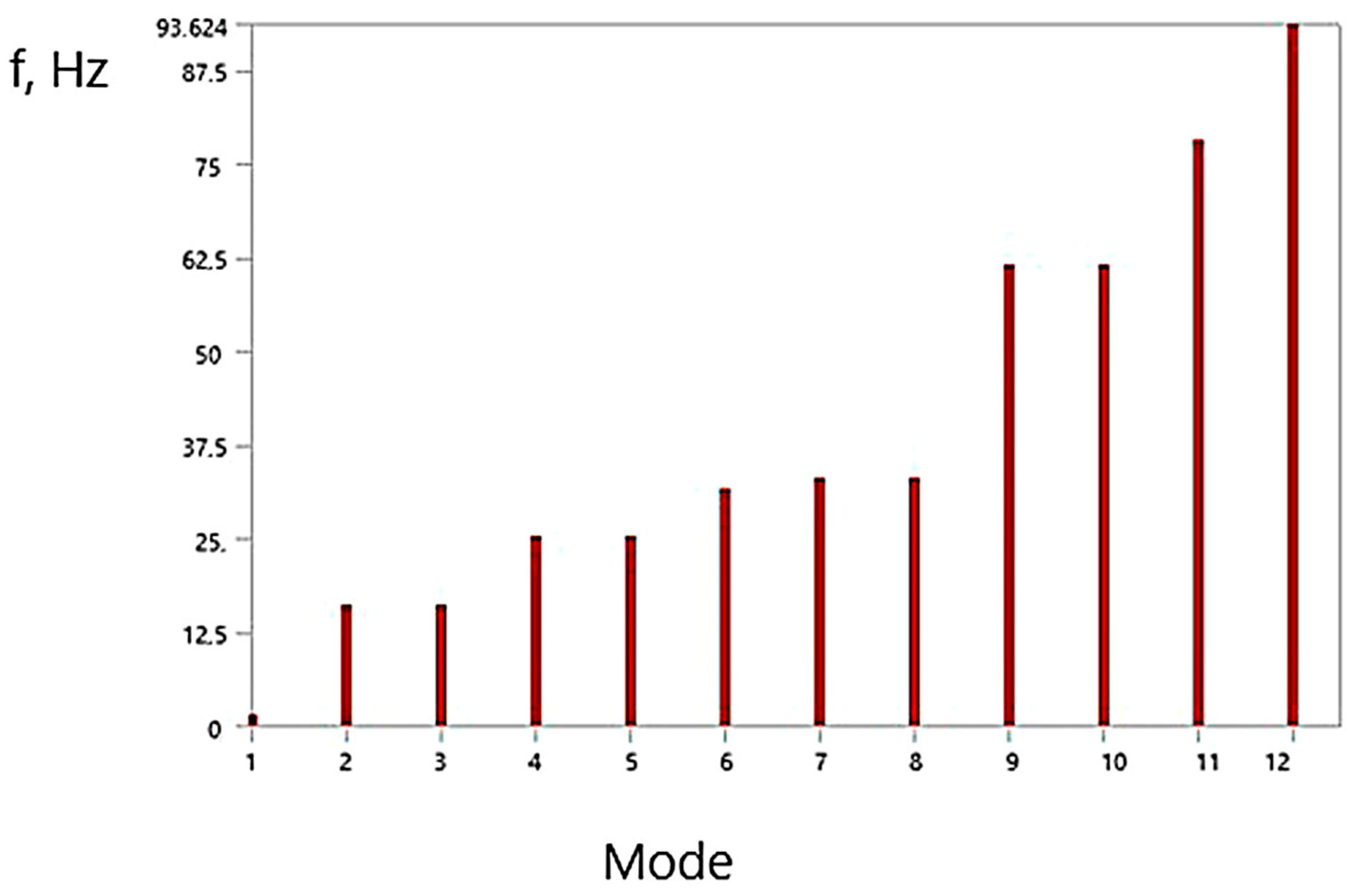
The modal analysis at the design stage optimizes the design in terms of resonant frequencies. As a result of the modal analysis, the forms of resonant vibrations of the propeller shaft system and the frequencies that correspond to them were obtained (
Figure 10). Based on the simulation results, the amplitude–frequency spectrum of the natural oscillations of the propeller shaft system in various modes was obtained. The forms and the description of the modes are given in [
13].
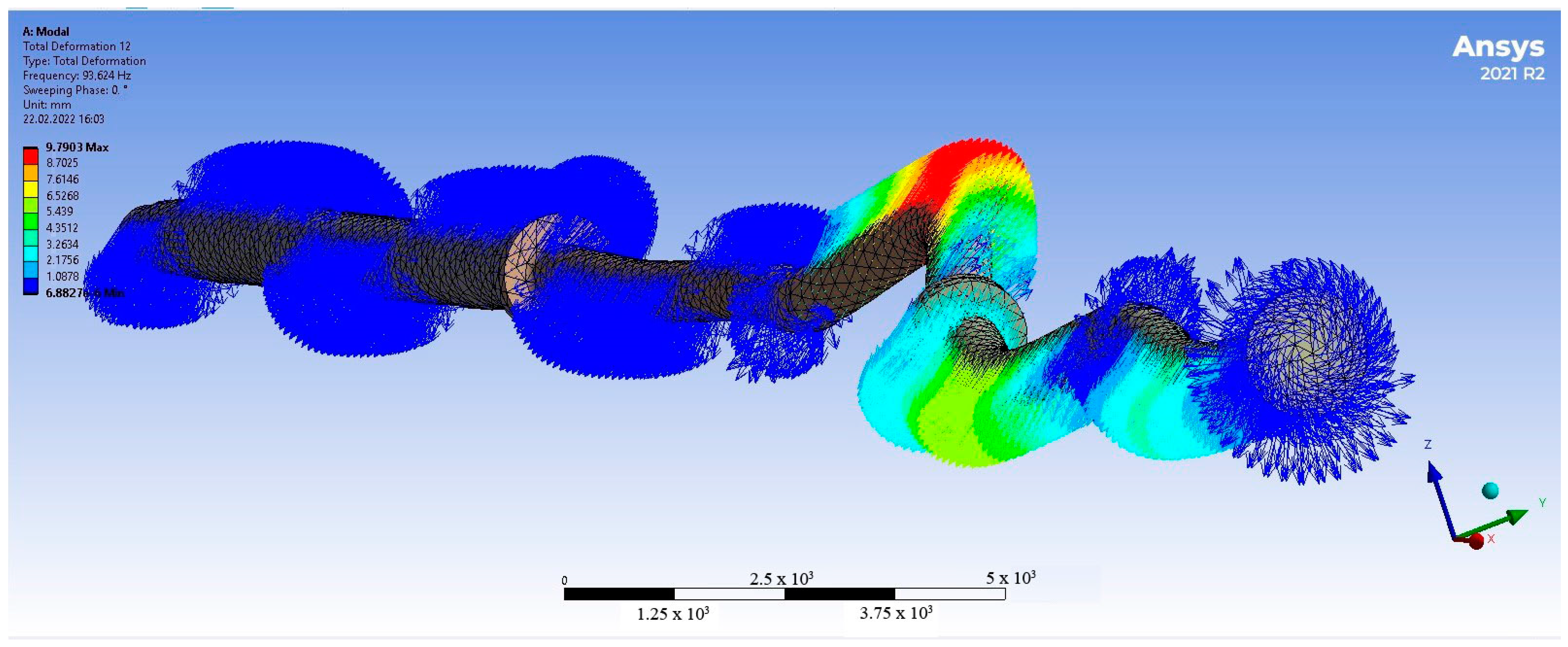
Figure 11 shows the twelfth mode of the natural oscillations of the shaft, as well as the shaft distortion.
After that, a harmonic analysis was conducted to obtain the system frequency response when the efforts were applied. The harmonic analysis showed the presence of high structural stresses near the flanges and platforms on which the bearing was mounted and fixed. The oscillation frequency during operation, according to the calculation, reached 150 Hz, which means that even the first resonant frequency was not reached.
3.4. Developing the Empirical Models of the Wear of Piston Rings of the Main Engine Based on Neural Networks
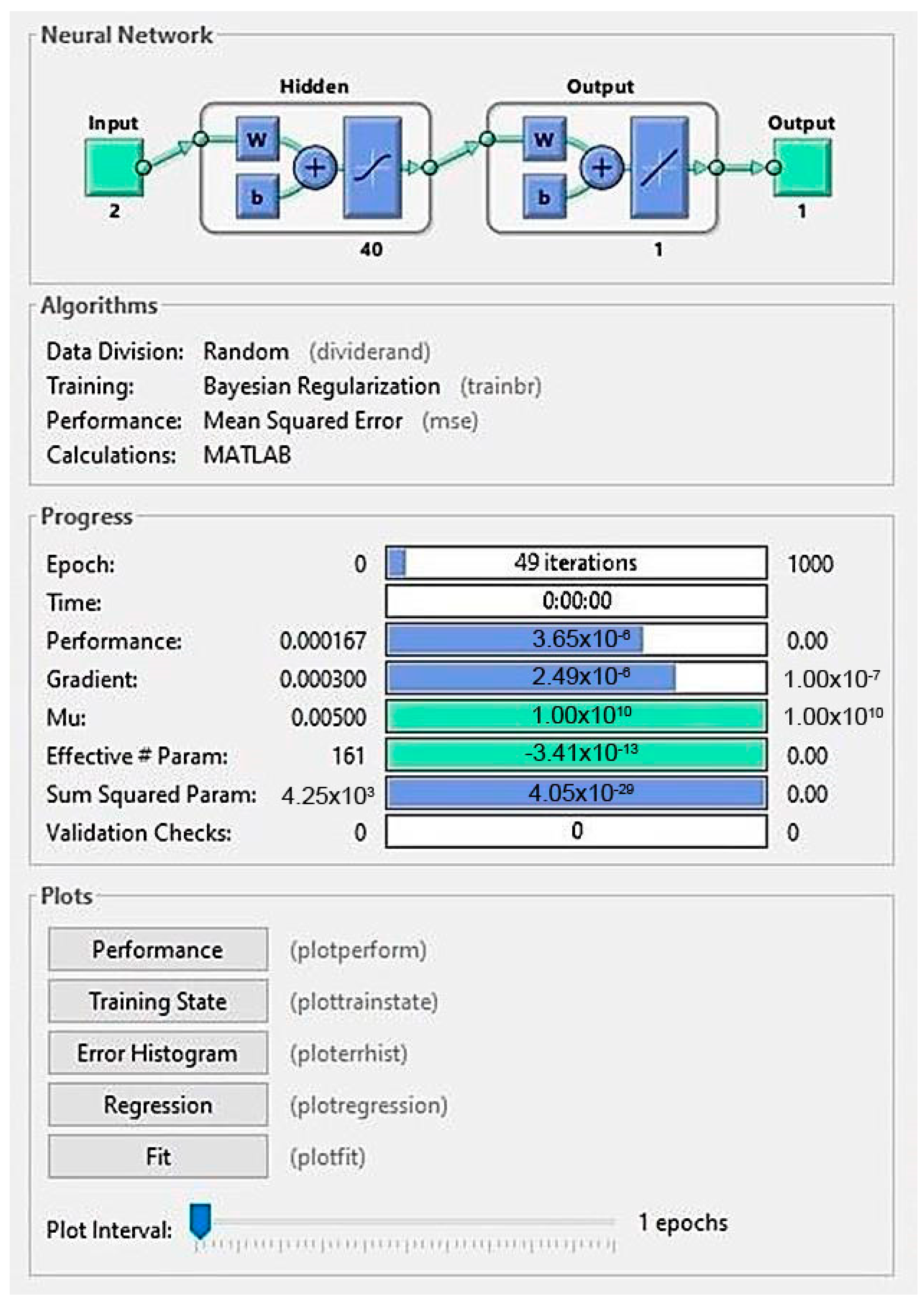
Describing the complex models that associate the wear of the elements of the ship’s electric power system with operating modes is difficult when using analytical methods. In this study, heuristic models based on neural networks, describing the relationship between the wear of diesel engine elements and engine operating modes, are proposed. The MatLab package is used to create a neural network.
The model used for assessing the wear of piston rings has a complex appearance and functions involving many parameters. Ne is the average effective power over the period, kW; ϕrel is the average relative humidity over the period, %; T is the average boost temperature over the period, C; S is the mass content of sulfur in the fuel, %; qm is the specific consumption of the cylinder oil, g/kWh. The surfaces of the rings are worn out as a result of friction against the piston while simultaneously burning the fuel. The inner surface of the rings has several functions: for example, insulation, heat exchange, and reduction in piston vibrations. In this regard, the description of the wear dynamics is a difficult task from the viewpoint of the analytical description. The factor analysis justifies the fact that the most significant factors in such a model are the power and the cylinder oil consumption.
The complexity of this model lies in the fact that the mutual influence of the factors can be ambiguous. Using the neural network for approximating the empirical data is effective in this case. The approximation of a complex relationship existing among the parameters by regression models in the form of a neural network can become a good platform for subsequent “fast” calculations performed for digital ship twins in the real-time mode. Based on the measurement results obtained for the diesel engine, the neural network (
Figure 12) was built on the ship (
Table 2), associating the wear of the piston rings with the operating modes. The calculations were performed for a tanker shipping crude oil. The main ship low-speed dual-fuel diesel engine, manufactured by Hyundai Heavy Industries (South Korea) under a license granted by MAN Energy Solution COSCO Long Beach (IMO 9285677), was chosen as the object of the calculations. The data on the wear of piston rings were obtained by applying an ultrasonic thickness gauge Elcometer of the 456 B SCALE 1 model used for metallic and non-metallic coatings. The data were obtained from the ship reporting documentation and were associated with the data on engine operating modes.
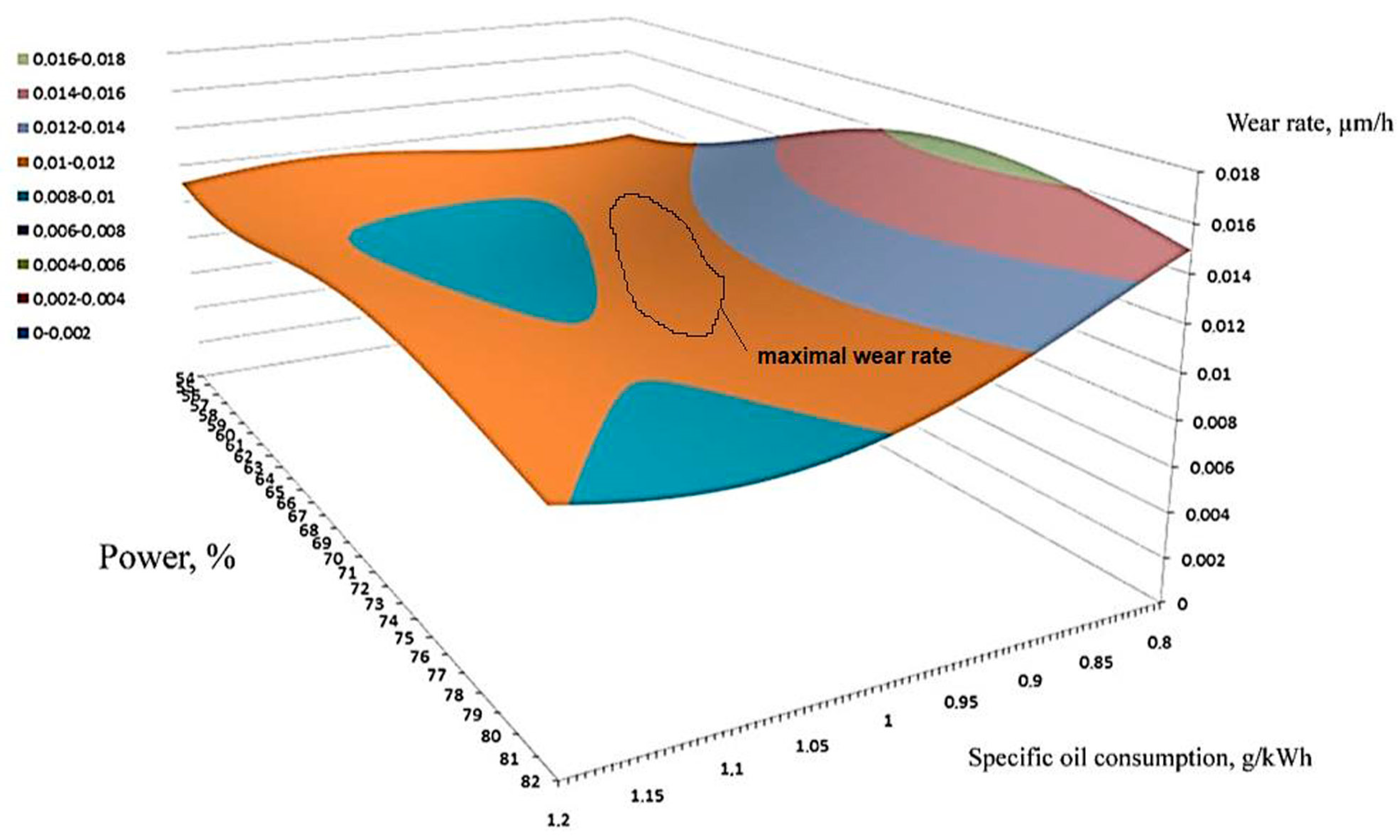
Figure 13 below shows a surface constructed by the neural network, describing the relationship among the wear intensity, power, and the specific consumption of the cylinder oil. The power and the specific oil consumption were measured along the axes of abscissa and ordinate; the wear intensity of the ceramic-metal coating was measured along the applicate axis.
The surface graph shows that there are combinations of extreme values of the power and the cylinder oil consumption, at which the wear is at a maximum.
It is obvious that under the maximum power in the case of the low fuel consumption, there is a slight wear of the rings, whose excess leads to a decrease in the wear. This information should be included in the accompanying documents, the inspection schedule, and the overhaul.
The resulting approximating dependence can be expanded by introducing new parameters, such as humidity and temperature, accompanied by an increase in the data set of the measurements and observations.
A similar method can be proposed to replace “heavy” models with “lighter” approximating complex dependencies, for example, the relationship of the models “the stress-strain state of the elements of the propeller shafting design—the probability of failure” in predictive diagnostics systems.
3.5. Simulating a Short Circuit in the Generator
In the context of a synchronous machine with three-phase windings, an excitation circuit, and both longitudinal and transverse damper windings, the set of differential equations governing the equilibrium of electromotive force (EMF) and voltage drops in the synchronous machine’s circuits can be expressed as follows:
where
and —values of voltage on the phase windings and the excitation windings, respectively;
and —current values of phase winding and field winding, respectively;
and —flux linkages of phase winding and field winding, respectively;
and —ohmic resistances of phase winding and field winding, respectively;
and —flux-coupling of the damper windings of the longitudinal and transverse components, respectively;
and —their active resistances; and —current values in damping circuits.
Equation (7) represents the differential equations describing the dynamics of electric machines. The calculation of the transient processes requires a joint solution of these equations supplemented with the expressions of the transformer and load voltage drops.
The dynamic processes proceeding in the electrical machines and networks are simulated to determine the setup variables in the algorithms that connect different levels [
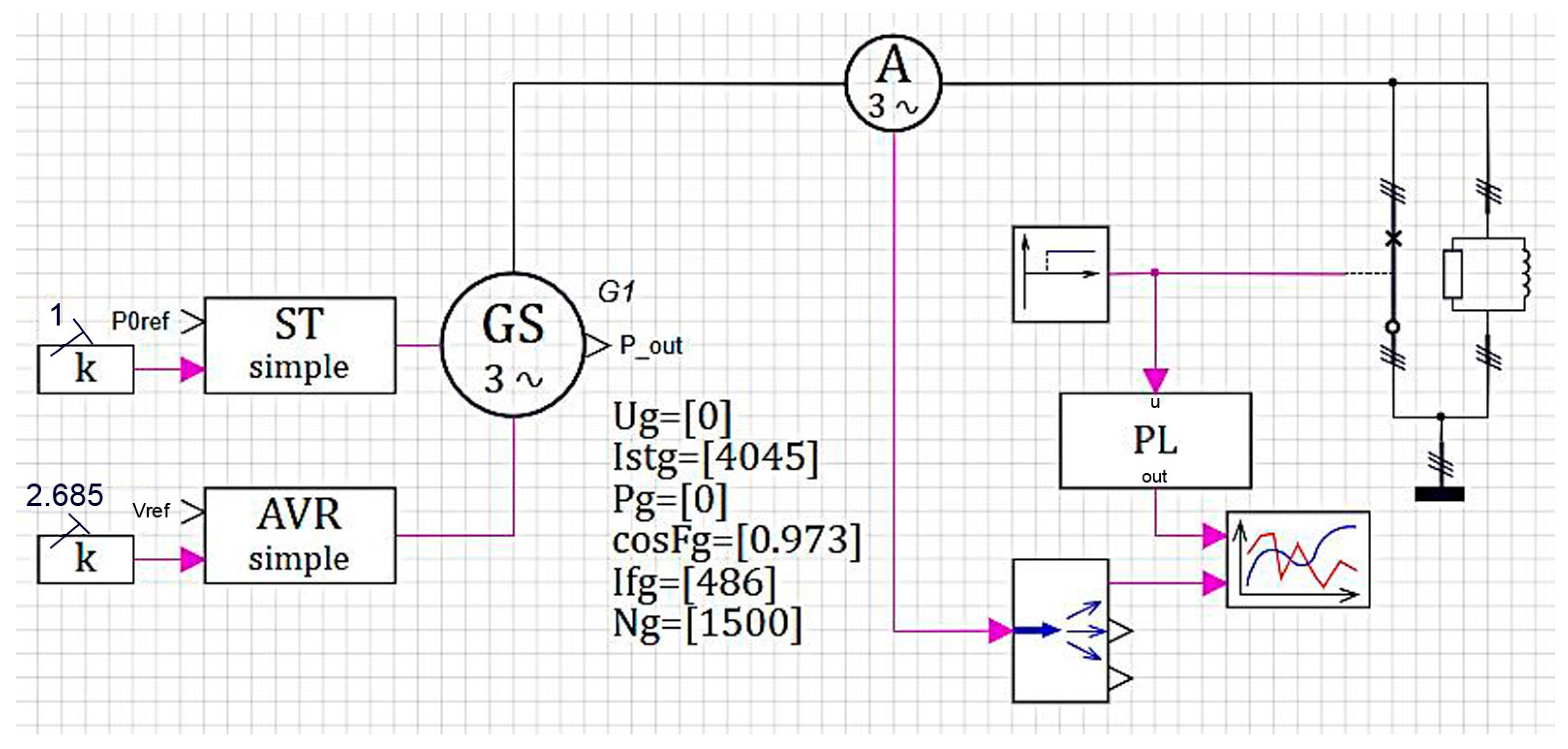
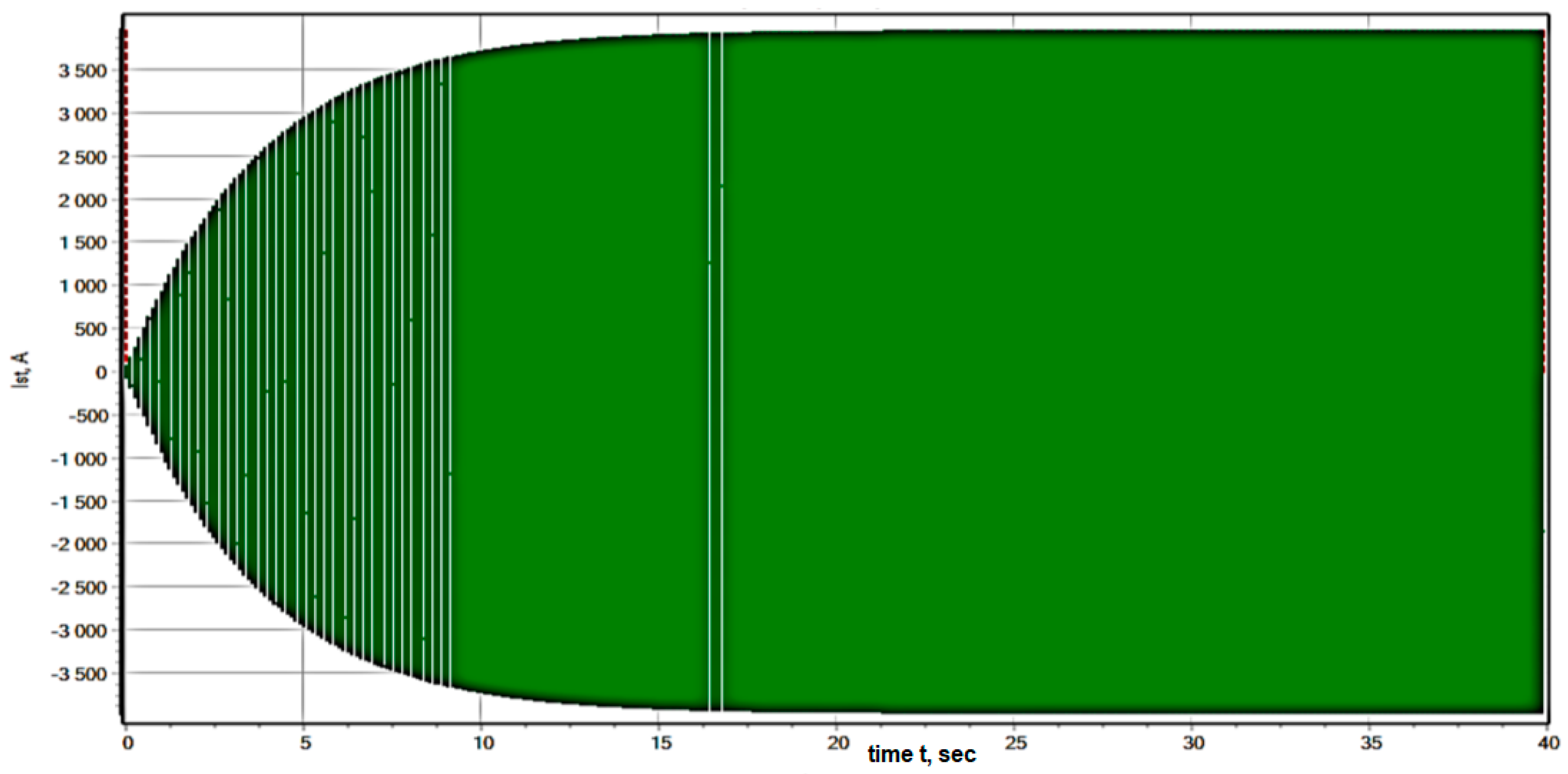
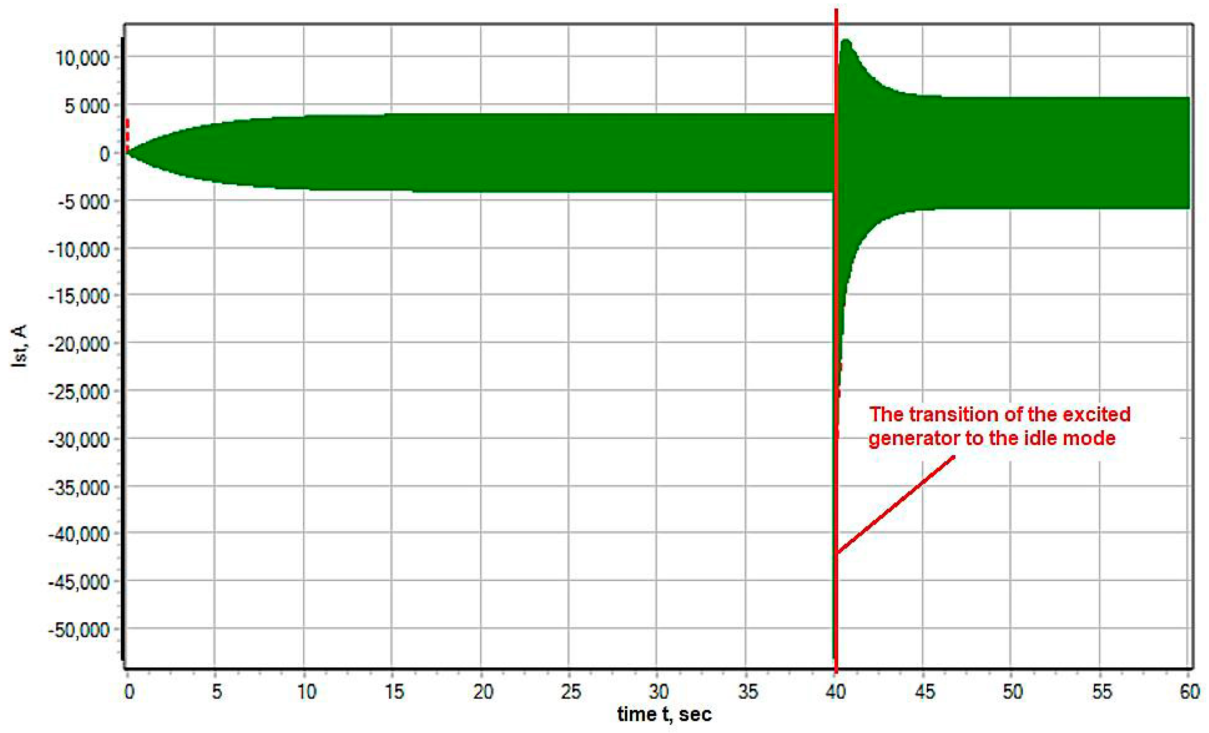
22]. An example of reaching the idling mode followed by a three-phase short circuit to one of the systems is presented below. The rotation speed of the generator ωt = 1 corresponds to the nominal one and does not change. At the time of 70 s, a three-phase short circuit occurs to the first three-phase system and the stator current increases taking into account an aperiodic component. Then, the aperiodic and periodic components fade to a steady-state value in accordance with the expressions (since the short circuit occurs in the idle mode, and the transverse component is absent).
Figure 14 demonstrates the dynamic model of a transient process occurring in the electrical circuit at the level of a physical short circuit process. The calculations were carried out for the tanker shipping crude oil.
To compare the calculation results with the theoretical values, the current of one phase of the generator in the short circuit mode is calculated. The analytical curve of the generator current lasting up to the short circuit moment is represented by a straight line having a constant value of 3600.9 A equal to the reference current (
Figure 15 and
Figure 16).
That is, at a time interval from 0 to 70 s, the excited generator goes into the idle mode. The generator stator voltage becomes close to the nominal voltage. This model facilitates studying the dynamics of the short circuit current.
3.6. The Object-Oriented Simulation of the Operation Process of the Ship’s Electric Power System
Using modern methods to solve the electromagnetic equations, describing the functioning of the electrical machines, provides great opportunities for studying transient processes. The influence of various mechanical factors, electrical factors, and operating conditions: eccentricities, mechanical damages, uneven laying of windings, elevated temperature, can also be considered.
Electric current is transmitted from the main distribution board to consumers via electric networks consisting of wires and distribution devices.
The main elements of the ship’s electric power system that make up the object-oriented model are:
- (1)
Electric power sources consisting of DC or AC generators and accumulator batteries; additionally, ship’s electric power systems have various converters of the current type, its voltage, and frequency;
- (2)
Distributing gears including the boards consisting of apparatuses, distributing electric power, and devices used for controlling the operation of electrical installations and monitoring them;
- (3)
Electrical networks consisting of cables and wires that transmit electric power from sources to consumers;
- (4)
Consumers of electric power, representing various electric motors that convert electric power into mechanical work, as well as devices and apparatuses that convert it into another type of energy: heat, light, electromagnetic, and others.
This work presents a solution to the problem of creating a virtual simulator of a ship’s electric power system. The mathematical model of this element belongs to the control models and is described by the equations of type (3).
A similar model facilitates systematically investigating the ship’s electric power system, simulating the dynamics, and making a decision on the satisfactory quality of the designing solution.
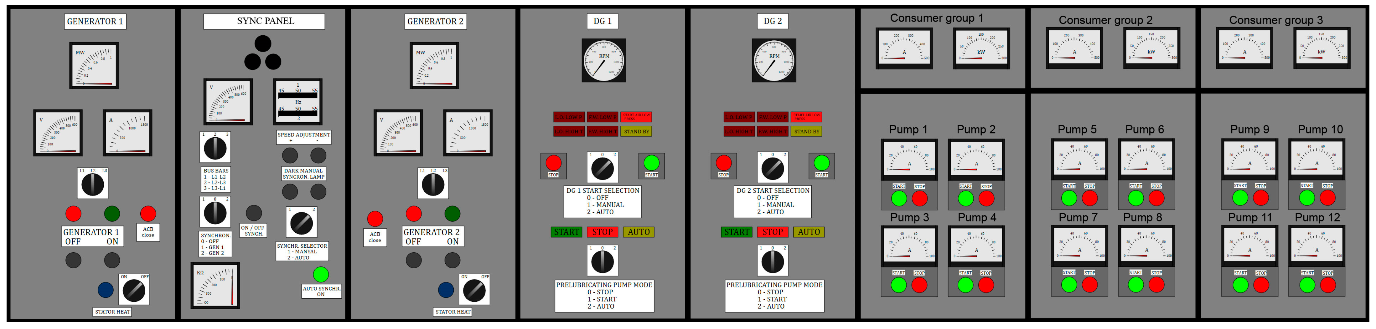
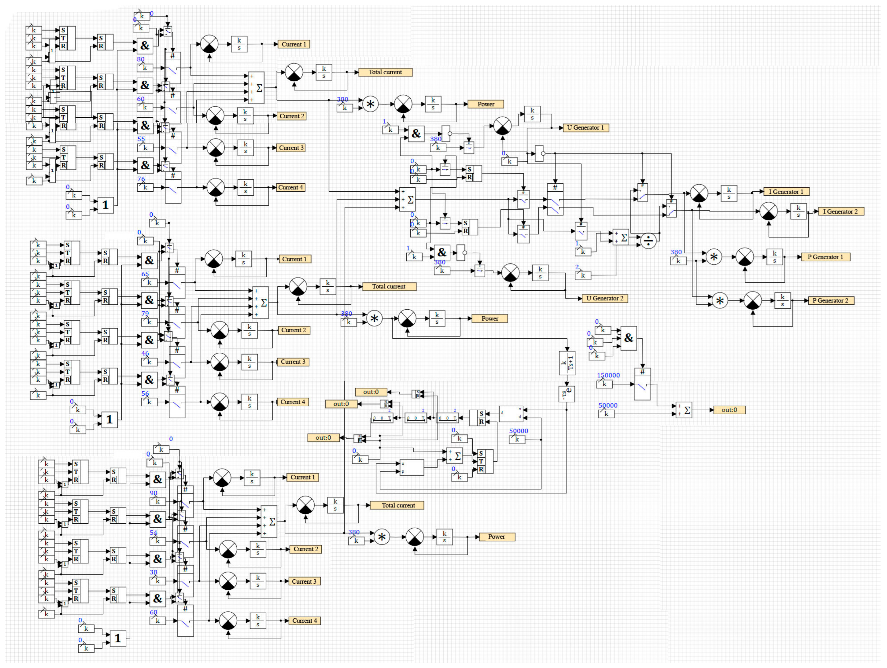
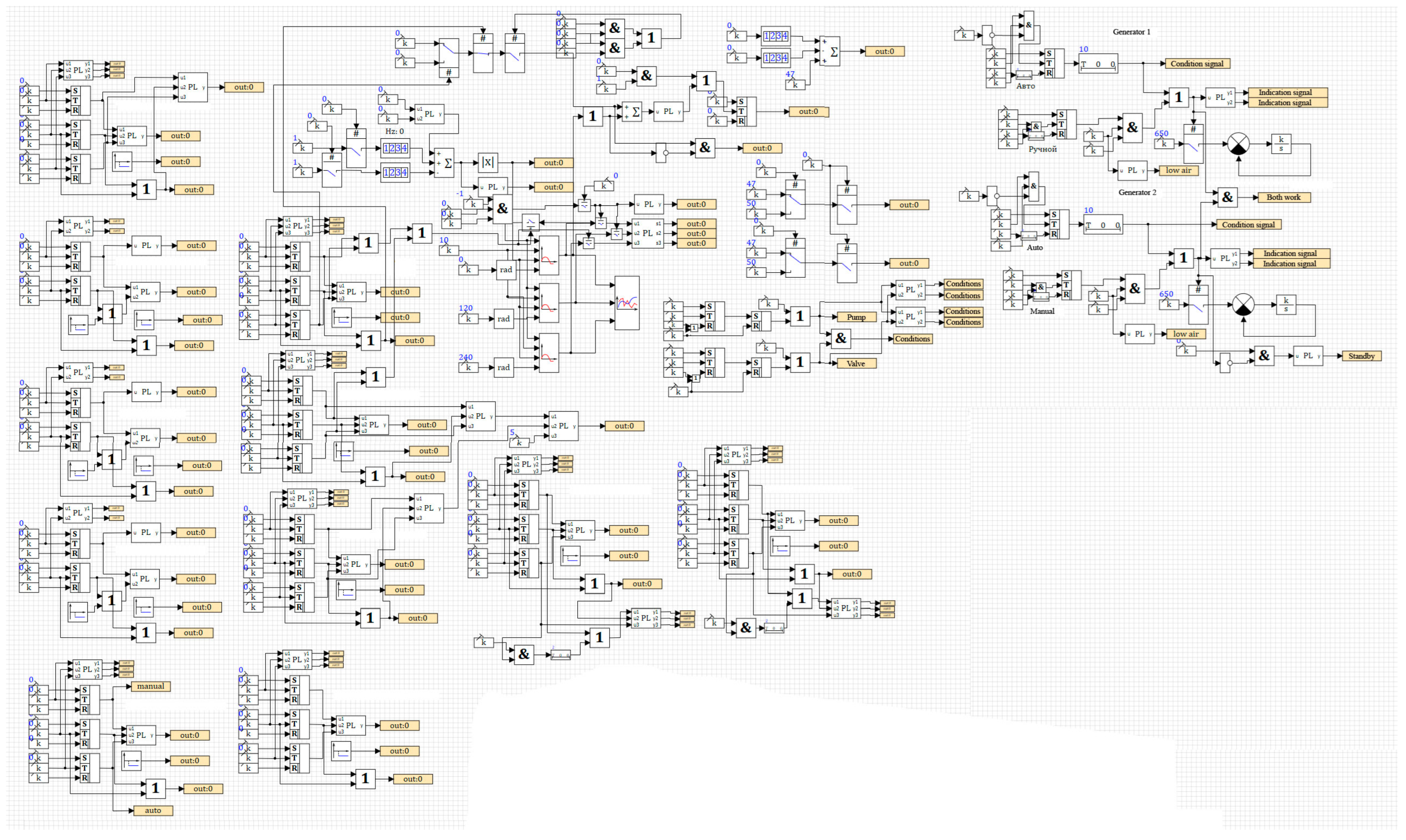
Figure 17 shows a model of the main distribution board (MDB) of a tanker used to ship oil, implementing the algorithms for controlling diesel generators (DG). The interface of this project consists of “primitives” formed into the constructions that are more complex. SimInTech can restore an animated or static graphic interface of any complexity without special efforts and connects them to the necessary parts of the model [
42].
The creation of the model required simulating eight sections of MDB, which are typical of a ship having two diesel power stations.
The number of logical and dynamic elements in this project exceeds 400 units, but the total number of elements in the work region amounts to 2400 units (
Figure 18 and
Figure 19).
The algorithms have been developed for the MDB operation: starting up diesel generators, the introduction into parallel operation. The algorithms provide manual and automatic control by diesel generators, conditions for stoppage, starting up, and switching.
This model works in the real-time mode and performs the tasks that correspond to the real tasks set on the ship MDB. The model performs its functions according to the logic of implementing the required conditions. All the MDB panels correspond to the logic of a real device and polish the solutions of various kinds of tasks:
Starting up DG in the manual mode, observing all the conditions for starting up;
Starting up DG in the fully automatic mode, where automation fulfills all the required conditions;
DG load management, switching on and off the pumps;
Simulating the short circuit conditions under loading;
Simulating the conditions for the moisture appearance in the stator windings;
Simulating the conditions of low pressure of the lubricating oil;
Simulating the conditions of high temperature of the lubricating oil;
Simulating the conditions of high temperature of the cooling water;
Simulating the conditions of low pressure of the cooling water;
Taking two diesel generators in parallel in the manual and fully automatic modes;
Demonstrating the work of the protection of active and reactive loads.
The developed MDB model promotes fully obtaining a stable simulation of the main ship distribution board, performing all possible manipulations with it, and providing a possibility of conducting practical works to familiarize with the object of simulation.
4. Discussion
The model of the engine wear (Mwear) associated with its operation modes is the initial one for the MDB operation algorithm (MMDB). The numerical model of the generator (Mgenerat) identifies defects and simulates the ship’s electric network. The operating frequency ranges of the main engines (Meng.), electric propulsion systems (Mgenerat), and their design peculiarities (disbalance, geometric inaccuracy, disequilibrium) are determined (Mdefect) both at the design stage and when eliminating problems arising on the operated ship using the numerical structural models. In addition, if there are measurement data of a real ship, the strength analysis allows for evaluating the fatigue strength and the reliability of a mathematical twin.
A description of the relationship between the operating modes of the equipment and the wear indicators of the engine elements (Mwear) using neural models is a promising direction. The modern ship equipment and the development of big data transmission and processing technologies make it possible to develop such an approach in predicting the engine operation processes. In this study, a neural network was used to simulate the wear of piston rings. The volume of the training sample is not as large as the number of the parameters, but this approach seems very promising, since similar models can be continuously supplemented and expanded. The nature of the processes proceeding in the main engines is continuous without a large number of local minima and maxima. That is, the approximating function of the neural networks is effective for simulation.
The information on the resonant frequencies of the propeller shaft system (Mshaft) allows for effectively designing the geometry and installing the “screw-propeller shaft–engine” (Mscrew, Mshaft, Meng.) system. The Register of Shipping facilitates the calculation of the natural frequencies and the determination of oscillation forms up to the twelfth inclusive.
The value of displacements in the case of different resonant forms of vibrations can be associated with the accuracy and calculation of the wear along the selected directions in the above-mentioned shaft system. The complex load and the evaluation of the shafting fluctuations can be set in the form of several boundary conditions: harmonic disturbances caused by the screw and the main engine, a geometric inaccuracy of structural elements, own weight, and interrelated fluctuations.
Structural, modal, and dynamic analyses of the propeller shafts (Mshaft) and other elements promote effective design and technological solutions in the field of reducing loads, vibrations, and resonances, which is the so-called reverse digital design. The digital twin of the shaft elements, simulating harmonic loads, applied according to the results of the measurements taken from a real active ship, is able to calculate and predict the fatigue strength of the structure to a higher accuracy. The variability and cheapness of such calculations by the dimension types and modes form a database for selecting the optimal states of the system as a whole (it should be noted that such calculations must be verified).
MDB (
MMDB), in turn, can be represented by algorithmic and dynamic object-oriented models. Hence, on the one hand, based on the micromodels (
Msc,
Mdefect,
Mwear), setpoints and discrimination thresholds in algorithms are assigned, and on the other hand, simulating the transient processes (
Mgenerat,
Meng.) makes it possible to build automation systems (
MAVR) for MDB (
MMDB). The object-oriented description of the dynamic systems simulates and predicts the ship system state or implements optimal control [
43,
44,
45].
Let us consider the following example for the above-mentioned ships as an illustration of the proposed approach [
46,
47,
48]. The shaft model
Mshaft obtained resonant frequencies and an operating frequency of 150 Hz for the shaft oscillations. This engine oscillation frequency corresponded to the engine power of 73% (
Meng.). This power value was compared with the wear value (
Table 2) according to
Mwear.
The numerical generator model (Mgenerat) determined the nature of the transient processes at a rotor rotation speed of 625 rpm at a frequency of 50 Hz. This model Mgenerat provided an opportunity for obtaining the characteristics of transient processes in the presence of a mechanical defect (Mdefect) in the generator (this was a harmonic component in the spectrum of a high amplitude force having a maximum value at a low frequency). This model Mgenerat also obtained the characteristics of transient processes in the presence of an electrical defect (Msc) or phase short circuit (the current was 15,000 A at 40 s, reaching an idling mode up to 70 s). The characteristics of the operating modes obtained based on the generator model Mdenerat (current, voltage, power, speed) were input values for the control model MAVR.
The algorithms of installing, starting up, and switching DE combined the Xsc vector and XD, Xwear vectors in the MDB model (MMDB) through the diagnostic model Mdiagn.
The local models and the research results described above, in turn, are already the objects and the states of the already formalized, complex, ranked image of the system. The system image includes the dynamics models, where the boundary and limiting conditions represent a common area for design and functioning tasks.
5. Conclusions
Modern ships are complex systems containing a large number of different elements. In the hierarchy of models, mathematical models of such elements belong to the microlevel and describe mainly the dynamics of various physical processes. At the same time, a mathematical apparatus based on the laws of conservation is used. In particular, this apparatus is represented by, for example, Maxwell’s equations, oscillation equations, Navier–Stokes equations, etc. Such models are preset by the equations of type (3). Since such equations describe physical processes of different natures, it is impossible to combine the mathematical models at the microlevel.
The application of microlevel models to specific processes (ring wear, shaft vibrations, generator processes, etc.) enables building macrolevel models, whose output parameters are in no way related quantities. The macrolevel models are connected by means of control models (Equation (4)). The control models belong to the metalevel and allow assigning settings and response thresholds in the algorithms used in automation systems (MDB model). Such a model (megalevel model) promotes, ultimately, the study of the dynamics of the entire system as a whole in terms of a change occurring in the full ranked image of ∏ (2) at each moment in time.
The approach (1)–(4) proposed by the authors connects the elements of a complex technical system and investigates its dynamics.
In summary, in this study, an approach to simulating a ship as a relationship of various systems was developed. The mathematical models were created for each of the composite systems and simulation results were presented. Each of the systems described a limited class of problems, had characteristic properties, and a mathematical structure. The models were interconnected using a set-theoretic description. The results of the conducted research can be used in modern intelligent digital platforms for support and decision-making when using maritime transportation, in control systems, and SCADA tracking.
The next step in the development of this work is to set mathematical optimization models and to conduct multi-criteria optimization to determine the optimal parameters of a complex technical system.


 ,
, 


