Abstract
In this study, a numerical investigation is conducted on combustion-driven pulsed-jet actuation to control the flow around a lifting surface. Based on relevant experimental measurements and computations, high-speed jets are generated from the impulsive variation in pressure at the actuator boundary. A supersonic jet flow is momentarily generated by combustion in a reaction chamber of the actuator, and the flow interacts with the external flow around the lifting surface and alters the aerodynamic characteristics. The computational results indicate that the flow control performance of the jet actuation is significant at a high-incidence angle of attack, such as beyond the stall angle, whereas the impact is minimal at low angles of attack, such as in the linear lift region. Repetitive jet actuation can produce additional momentum to the external flow and alters the pressure distribution on the suction surface, particularly downstream of the actuator location. This pressure variation from the actuation yields an additional lift force on the lifting surface and reduces the amplitude of the aerodynamic moment at a given angle of attack, thus enhancing the aerodynamic performance of the airfoil.
1. Introduction
Flow separation can occur around lifting surfaces at high-incidence angles, limiting their aerodynamic performance and flight envelope. Various flow control techniques have been studied to control the separating flow and recover aerodynamic performance [1,2]. Gad-el Hak [1] reviewed various flow control techniques for the realization of desired impacts, such as lift augmentation, drag reduction, and separation prevention. Ashill et al. [2] reviewed the key advantages and challenges associated with flow control devices, including passive and active methods. Their report indicated that passive flow control devices (e.g., vortex generators, miniature trailing-edge effectors, grooves, and riblets) can easily be installed and do not require extra energy input. However, unexpected drag penalties might occur in high-speed flow conditions. Slats and flaps, which are active flow control techniques with geometric variation, can control external flows effectively. Nevertheless, exploiting these methods for certain scenarios where a brief response is required might be challenging.
Various actuation methods have been explored to control the aerodynamic characteristic of a lifting body [3,4,5,6,7,8,9,10,11,12]. Müller-Vahl and Greenblatt [3], Kim et al. [4], and Gardner et al. [5,6,7] focused on the impact of a steady-blowing jet on lifting surfaces, revealing changes in aerodynamic characteristics with the use of a high-momentum steady-blowing jet. Feng et al. [8] assessed the effects of constant suction actuation at different locations on a plunging SD7003 airfoil, using RANS computations for analysis. The potential of plasma actuation in stall control has also been a subject of research [9,10]. Post and Corke [9] observed that employing a plasma actuator near the leading edge not only enhanced the lift but also mitigated the sharp decline of the lift during the downstroke. Yu and Zheng [10] demonstrated the effectiveness of nano-second plasma actuation in reducing dynamic stall events in their RANS computational studies. Additionally, zero-net mass-flux, commonly known as synthetic jet actuation, has been applied in dynamic stall control scenarios [11,12]. Rehman and Kontis [11] successfully used a synthetic jet to improve the aerodynamics of a NACA 0015 airfoil. Taylor and Amitay [12] conducted experiments with a synthetic jet actuator installed on a finite-span wing, showing that periodic momentum injection near the leading edge can effectively suppress the recirculation region.
Pulsed-type fluidic actuation via combustion, a key focus in this study, employs high-velocity jet impulsive actuation [13,14,15]. This technique, known as combustion-powered actuation (COMPACT), involves generating a high-speed jet from a combustion process in a small chamber, about 1 mL in volume (see Figure 1). Crittenden et al. demonstrated that this process can produce a supersonic jet due to rapid pressure increases within the chamber, leading to the flow choking at the chamber’s outlet. The absence of moving parts in COMPACT devices aids in initiating high-frequency combustion, up to 200 Hz, allowing for integration into the internal structure of the wings, especially near the leading edge. Crittenden et al. [13,14,15] indicated that a minimal electrical ignition energy of 2 mJ was sufficient for igniting hydrogen in the combustion process. Furthermore, they reported that a hydrogen/air mixture undergoing combustion in a 1 mL chamber results in an energy release of approximately 3.2 J, which is three orders of magnitude higher than the initial electrical energy input.
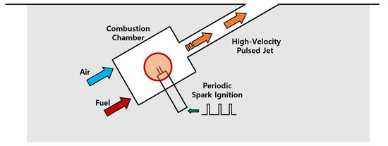
Figure 1.
Schematic diagram of high-speed jet generation from combustion-powered actuation.
Brzozowski et al. [16] and Woo et al. [17] tested this method on a stalled NACA 4415 under incompressible flow conditions and demonstrated a rapid increase in circulation in the experimental measurements. Woo et al. [18] used this actuation for the rotor–body interaction and demonstrated a reduction in the aerodynamic drag of the fuselage. Matalanis et al. [19,20,21] and Tan et al. [22] utilized COMPACT actuation to control the dynamic stall phenomena under various flow conditions. Jee et al. [23] and Kim et al. [24,25,26] applied this flow control technique to mitigate rotorcraft-related dynamic stall events using unsteady Reynolds-averaged Navier–Stokes simulation (URANS) computations. Later, Kim et al. [27] conducted a delayed detached-eddy simulation (DDES) to investigate detailed flow physics with the jet actuation, and they identified two distinct time scales associated with the flow features closely related to variations in the aerodynamic performance of a lifting body.
Recent relevant computational studies employing large-eddy simulation (LES) and direct numerical simulation (DNS) [28,29,30,31,32,33] have emphasized their substantial computational demands for simulating lifting surfaces, whether stationary or in motion, under compressible flow conditions, like high Mach and Reynolds numbers. These high-fidelity computations [30,31,32] are essential for a detailed understanding of the physics of lifting surfaces, utilizing simple geometries, such as unmodified wings. However, the application of these computations is still limited to certain low-speed flow conditions. On the other hand, the unsteady Reynolds-averaged Navier–Stokes (URANS) approach has been effectively utilized for aerodynamic simulations under compressible flow conditions [34,35,36,37,38,39,40,41]. Furthermore, ongoing research in the area of flow control [8,10,24,25,26,42] indicates the continued relevance of the URANS approach for investigating flow mechanisms, complementing experimental studies.
In this study, high-speed jet actuation was applied to a lifting surface to control the aerodynamic performance. The experimental study by Ladson et al. [43,44] was simulated as a baseline airfoil case, and jet flows were applied using the same actuating configurations as in the wind tunnel tests by Matalanis et al. [19,20,21]. The computational results were validated using the related experimental data. The remainder of this paper is organized as follows: The computational methods and actuator models are presented in Section 2. The computational results, including the baseline and actuated cases, are described in Section 3. Finally, the conclusions of this study are presented in Section 4.
2. Computational Methodology
The flow around the NACA 0012 airfoil tested in [43,44] is simulated as the baseline case. The flow conditions of the current simulations are and , based on the freestream velocity , air density , and viscosity . The moment center is located at . The actuator is tangentially installed at on the suction surface of the airfoil, at the same location as the actuator slot tested in the previous related experiments by Matalanis et al. [19,20,21]. The jet angle, based on the slot exit, is approximately , and the jet height is .
The conservative forms of the compressible Navier–Stokes equations are solved numerically using NASA’s flow solver CFL3D. A detailed numerical implementation of the generalized coordinates to Navier–Stokes equations is well documented in References [45,46,47,48,49]. In this section, only substantial information on the coordinate transformation will be discussed. The time-dependent compressible Navier–Stokes equations in generalized coordinates are expressed as
The conservative variables are
where J is the Jacobian of the transformation, ; is the fluid density; is the flow speed in the direction; and e is the total energy per unit volume. The vectors (, , ) and (, ) are the Euler and viscous fluxes of a generalized coordinate system in a , , and direction, respectively.
Euler and viscous fluxes are
where
The viscosity is calculated using Sutherland’s law [50]:
where the coefficients are = 1.717 kg/m s, K, and K. More details of the flow solver CFL3D, including the grid system and coordinate transformation, are summarized in [49].
The Roe flux-differencing scheme [51] is used for the Euler fluxes with third-order MUSCL, and central differencing is used for the viscous fluxes. A second-order dual-time-stepping method is used for temporal integration [52,53]. The time step size with respect to the convective time scale and pulse duration is , and the Courant–Friedrich–Lewy number for the inner iteration is 0.8 with 20 iterations to converge the inner iterations. A multigrid technique is used for every iteration to accelerate the solution convergence. The URANS is performed using the Spalart–Allmaras (SA) turbulence model [54]. The transport equation of the SA working variable is expressed as
The turbulent viscosity is computed as , where and . Additional definitions and constants are summarized in [54]. The freestream condition for the SA variable is based on previous studies on freestream conditions for a fully turbulent simulation [55,56].
The computational grids are generated around the actuator-installed NACA 0012 airfoil, as shown in Figure 2. A c-type grid system is used to solve the external flow around the airfoil, and additional grids are applied to the actuator slot at . Four computational grid systems (fine, medium, coarse, and coarser) are tested with no actuation. The corresponding grid qualities are summarized in Table 1. Figure 3 shows the aerodynamic forces and moment of the baseline airfoil with respect to the different grid qualities listed in Table 1, and grid convergence is achieved at the medium grid level. Therefore, the medium and fine grids provide indistinguishable similar results. In this study, a fine grid is used for the rest of the computations, consisting of and for the grid points in the external flow and actuator slot, respectively. The height of the first wall-normal grid point is in the wall unit. The freestream boundary is located away from the airfoil surface. The adiabatic wall condition is applied to the airfoil surface and slot walls, and the actuator boundary condition for high-speed jet generation [26,27] is applied to the slot bottom. This is detailed in the results section.
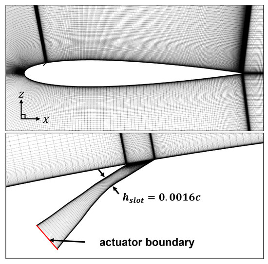
Figure 2.
Computational grids around the NACA 0012 airfoil and the actuator slot. Only the fine grid is shown in the figure.

Table 1.
Computational grids tested in the current simulation. The parameter N is the number of grid points, and the subscripts , , and indicate the external flow, actuator slot, and wake region, respectively. and are the grid length at the leading and trailing edges, and is the dimensionless height of the first wall-normal grid point in the wall unit.
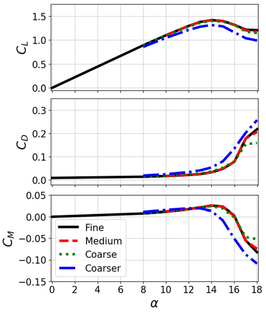
Figure 3.
Aerodynamic forces and moment on four grids.
3. Computational Results
The aerodynamic forces and moment of the baseline NACA 0012 without actuation are compared with those in previous studies, as shown in Figure 4. The current computational data are time-averaged over 20 in a quasi-steady state after a sufficient time of 20 from the initial condition and compared with the related experimental [43] and numerical data [57]. Herein, the turbulent simulation data of [57] were obtained from a fully turbulent simulation using the SA turbulence model [54], which is the same numerical approach used in the current study. The baseline computation in this study showed good agreement with the related experimental and numerical data, as shown in Figure 4. The stall angle is predicted to be , and the forces and moment are consistent with the experiment.
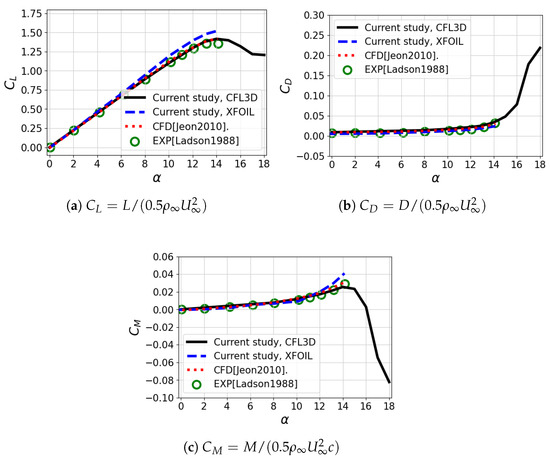
Figure 4.
Aerodynamic forces and moment of the baseline NACA 0012 airfoil compared with [43,57].
The surface pressure distribution around the baseline airfoil is compared with the experimental data, as shown in Figure 5. The computational results of the two selected angles of attack and are compared with the experimental results of [44] and showed good agreement with the test data. Here, the Reynolds number in the pressure measurements of [44] is slightly lower than the current flow condition, i.e., than , but the numerical results show an insignificant discrepancy with the experimental data, as shown in Figure 5. As both angles of attack are close to a linear lift region, a mild variation in the surface pressure is observed after the suction peak, implying a well-attached flow on the overall suction side. A minor pressure oscillation is observed locally at . This is primarily owing to the actuator slot installed therein, which impacts minimally on the entire surface pressure distribution around the lifting body.
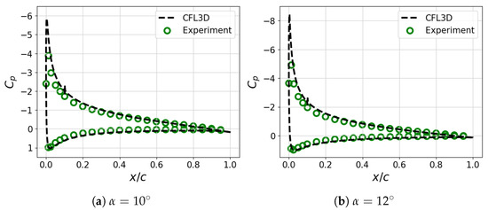
Figure 5.
Surface pressure distribution around the baseline NACA 0012 airfoil.
The actuation pressure is assigned to the bottom surface of the slot as the boundary condition based on the experimental measurements. In the wind tunnel tests by [19,20,21], jet flows were generated from an impulsive variation in pressure inside a combustion chamber. For this computation, impulsive pressure variation is applied at the slot bottom using a pressure ratio and pulse duration , instead of modeling the entire combustion process. The peak pressure ratio and pulse duration in the current computation are and , which are the reported values in the experimental measurements by [20,21]. The boundary conditions at the bottom of the actuator slot are applied by following the approach of [26,27] and summarized in Equations (13) and (14).
where the subscript and denote the actuating and non-actuating periods, respectively. Finally, the change in the actuation pressure is obtained using Equation (15):
The variation in pressure is visualized in Figure 6. The actuation temperature is calculated using the ideal gas law with the actuation pressure , freestream density , and gas constant R. In this study, the freestream pressure is set as the reference actuating pressure . The non-dimensional actuation frequency is used to identify the flow control authority of the repetitive actuation. The non-dimensional frequency of implies the identical contribution from the pulse frequency and convective frequency , and it corresponds to the dimensional actuation frequency of ( Hz) for an airfoil with a chord length on the order of (1 m). The characteristic inflow boundary condition is used in the pulse duration to drive the high-speed jets from the pressure variation, and the zero-mass-flux boundary condition is used between the pulse intervals.
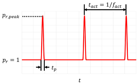
Figure 6.
A schematic diagram of impulsive variation in pressure at the actuator boundary.
A high-momentum jet is generated from the impulsive variation in pressure at the actuator boundary, as shown in Figure 7. The momentary pressure increment chokes the flow at the nozzle throat and produces a supersonic jet flow on the suction side. The jet flow covers the downstream of the slot exit, which can interact strongly with the external flow, and provides additional momentum to the boundary layer. The current numerical approach to the actuator boundary is verified by comparing the jet momentum coefficient with the experimental value, which is a key parameter of pulsed-type actuators for flow control [58]. The peak jet momentum coefficient is evaluated using the flow properties at the nozzle throat and compared with the reported experimental value of [21]. The current study shows , which is similar to the experimental value reported in [21]. Subsequently, repetitive jet actuation is applied to the airfoil using an actuation frequency identical to the freestream convection, i.e., , and the change in aerodynamic characteristics is assessed. The computational data are time-averaged over 20 in a quasi-steady state after a sufficient time of 20 from the baseline result.
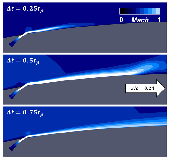
Figure 7.
High-speed jet generated from impulsive actuation. White region indicates supersonic flow.
The results in Figure 8 show the variations in the aerodynamic forces and moment with the actuation and indicate that repetitively pulsed jets can enhance the aerodynamic performance of the lifting surface. The flow control impact is particularly significant for the near- and post-stall angles of attack, e.g., , in the baseline case. The lift force in the near- and post-stall regimes noticeably increases compared with the baseline airfoil, along with a variation in the drag. The amplitude of the aerodynamic moment is reduced at a given angle of attack. Although the actuated stall angle does not change with the jet flow, it exhibits a gradual post-stall behavior of forces and moments compared with the baseline case.
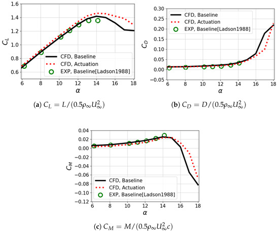
Figure 8.
Aerodynamic forces and moment of the actuated NACA 0012 airfoil compared with [43].
Conversely, at low angles of attack, the flow control impact of the impulsive actuation becomes minor; therefore, minimal variations in the aerodynamic forces and moment are observed. The related experimental [19,20,21,22] and computational [23,24,25] studies reported that jet actuation could have a minor impact on the flow control where the external flow is well attached to the surface. This is probably related to the minimum variations in the forces and moment observed in the current computations at low angles of attack, where the flow is already well attached to the suction surface.
The time-averaged pressure field around the airfoil is visualized as shown in Figure 9, which is related to the aerodynamic variations observed in Figure 8. Two angles of attack are selected in the pre- and post-stall regions, and the results are associated with the force variation observed in Figure 8. At , both the computational results in the baseline and actuation exhibit qualitatively indistinguishable data around the airfoil (Figure 9a). This result is associated with a marginal difference in forces and moments at low angles in Figure 8. At a high-incidence angle of , the actuation successfully alters the pressure distribution around the airfoil. Multiple jet flows reduce the suction pressure near and downstream of the actuator. Thus, the flowfields exhibit a visual difference, as shown in Figure 9b, enhancing the aerodynamic performance of the lifting body.
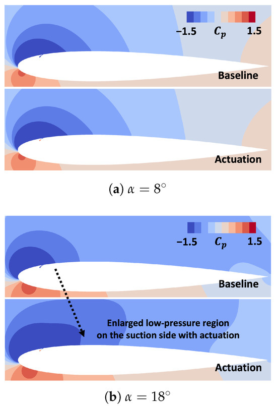
Figure 9.
Pressure field around the NACA 0012 airfoil with and without the actuation.
The surface pressure distribution around the actuated airfoil is quantitatively assessed, and it demonstrates a meaningful flow control impact for a high-incidence angle, as shown in Figure 10. At the angle of attack , the impact of the jet flows is significant and produces a large pressure loop compared with the baseline case (see Figure 8). The repetitive actuation yields a low pressure particularly around on the suction side, generating an additional lift force on the lifting surface. This may be related to the additional momentum applied to the boundary layer downstream of the actuator location , altering the pressure distribution on the suction side. Because the pressure variation in the suction side is concentrated in the upstream region to the pitch axis , the pitch-down moment amplitude is diminished compared with the baseline.
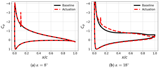
Figure 10.
Surface pressure distribution around the actuated NACA 0012 airfoil.
However, the repetitive jet actuation yields an insignificant difference at . The surface pressure around the actuated airfoil exhibits an almost identical distribution to that of the baseline case (see Figure 8). This is associated with a minimum difference in the forces and moments at low angles of attack, as shown in Figure 8. Previous related experimental and computational studies [20,21,25] reported similar results for an attached boundary layer, implying there is a minor flow control impact of the jet actuation for a well-attached flow.
The variations in the time-average near-wall velocity with the actuation are shown in Figure 11, which are associated with the aerodynamic variations observed in Figure 8, Figure 9 and Figure 10. Three selected locations downstream of the actuator, , , and , are evaluated, which shows the pressure changes with the actuation. The streamwise velocity is normalized with the maximum peak value obtained in the baseline, and the wall-normal distance y is scaled using the wall-normal length where the peak velocity occurred. The computational result at (Figure 11a) shows an enhancement of the flow near the wall region, which implies that the jet actuation enhances the flow at the location. The baseline case at in Figure 11b exhibits a mild reverse flow near the wall, but the actuation alters the velocity profile, so the flow is attached to the suction side with the actuation. These results might be related to the mitigation of the severe flow separation observed at in the baseline (Figure 11c), which could imply a delay of the separating location associated with the aerodynamic variation observed.
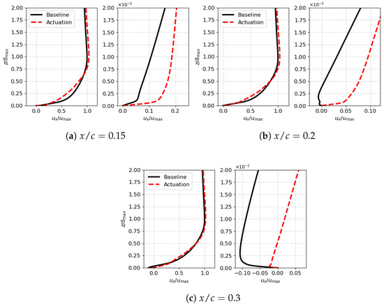
Figure 11.
Variation in streamwise velocity in the near-wall region at three selected locations on the suction side. Velocity is normalized with the peak value, , in the baseline case, and the wall-normal distance z is scaled using where the location of is in the wall-normal direction.
The current computational investigations have revealed that high-speed jet actuation can control the aerodynamic performance of a lifting body. The computational approach on the actuator boundary can produce a supersonic jet in the computational domain and shows comparable momentum to the relevant experimental measurements. The jets from the repetitive actuation strongly interact with the external flow and produce additional momentum to the boundary layer. They change the pressure distribution on the suction side and generate additional lift force to the lifting surface. Consequently, meaningful variations in the aerodynamic characteristics are observed with the actuation, particularly for high-incidence angles.
The computational analysis has revealed that the use of repetitively pulsed-jet actuators significantly improves the aerodynamic performance of airfoils under high angles of attack, notably in near-stall and post-stall conditions. This improvement is seen in the increased lift coefficient and changes in the drag coefficient, along with a decrease in the moment coefficient at these higher angles. However, the effectiveness of these actuators is less marked at low angles of attack, where the flow remains consistently attached to the airfoil. In such scenarios, the changes in the aerodynamic coefficients are minimal. These findings suggest that while jet actuation is effective in addressing major flow separations like those in deep stall events, its impact is reduced in situations with an already stable flow attachment. This points to the potential for the focused application of jet actuators in aerodynamic control, particularly in managing complex stall situations.
4. Conclusions
In this study, pulsed-jet actuation was numerically investigated to control the aerodynamic characteristics of a lifting body. A flow control method was applied to a baseline flow around the NACA 0012 airfoil under compressible flow conditions. An actuator boundary condition was constructed to produce jets in the computational domain based on measurements reported in prior wind tunnel experiments. An impulsive pressure variation, which choked the flow at the nozzle throat, was assigned at the slot bottom. This drove the supersonic jet to the external flow on the suction side, and the current numerical approach exhibited a comparable peak momentum of the jet flow reported in the related experimental studies.
The computational results with the repetitive jet indicated that the actuation had a meaningful impact on the flow control for separated flows at high-incidence angles, whereas it exhibited minimal changes for well-attached flows at low angles of attack. Owing to the strong interaction between the jet and external flow, the surface pressure distribution on the suction side was altered, particularly downstream of the actuator. A larger pressure loop, compared with the baseline case, generated an additional lift force on the airfoil and reduced the amplitude of the aerodynamic moment at a given angle of attack, enhancing the aerodynamic characteristics of the lifting surface.
Author Contributions
Conceptualization, T.K. and I.S.; methodology, T.K. and I.S.; software, T.K.; validation, T.K. and I.S.; formal analysis, T.K. and I.S.; investigation, T.K. and I.S.; resources, I.S.; data curation, T.K.; writing—original draft preparation, T.K. and I.S.; writing—review and editing, T.K., S.P. and I.S.; visualization, T.K. and S.P.; supervision, I.S.; project administration, I.S.; funding acquisition, I.S. All authors have read and agreed to the published version of the manuscript.
Funding
This work was supported by the Korea Institute of Science and Technology Information (KISTI), an institutional R&D Program (K-23-L02-C05) with the NURION supercomputing resources, including technical support (TS-2023-RE-0016).
Data Availability Statement
The data presented in this study are available on request from the corresponding author.
Conflicts of Interest
The authors declare no conflict of interest.
References
- Gad-el-Hak, M. Flow Control—Passive, Active, and Reactive Flow Management; Cambridge University Press: Cambridge, UK, 2007. [Google Scholar]
- Ashill, P.R.; Fulker, J.L.; Hackett, K.C. A review of recent developments in flow control. Aeronaut. J. 2005, 109, 205–232. [Google Scholar] [CrossRef]
- Müller-Vahl, H.F.; Strangfeld, C.; Nayeri, C.N.; Paschereit, C.O.; Greenblatt, D. Control of Thick Airfoil, Deep Dynamic Stall Using Steady Blowing. AIAA J. 2015, 53, 277–295. [Google Scholar] [CrossRef]
- Kim, J.; Park, Y.M.; Lee, J.; Kim, T.; Kim, M.; Lim, J.; Jee, S. Numerical Investigation of Jet Angle Effect on Airfoil Stall Control. Appl. Sci. 2019, 9, 2960. [Google Scholar] [CrossRef]
- Gardner, A.D.; Richter, K.; Mai, H.; Neuhaus, D. Experimental Investigation of Air Jets for the Control of Compressible Dynamic Stall. J. Am. Helicopter Soc. 2013, 58, 1–14. [Google Scholar]
- Gardner, A.D.; Richter, K.; Mai, H.; Neuhaus, D. Experimental investigation of high-pressure pulsed blowing for dynamic stall control. CEAS Aeronaut. J. 2014, 5, 185–198. [Google Scholar] [CrossRef]
- Gardner, A.D.; Richter, K. Effect of the Model-Sidewall Connection for a Dynamic Stall Airfoil Experiment. J. Aircr. 2019, 57, 173–178. [Google Scholar] [CrossRef]
- Feng, L.H.; Li, Z.Y.; Chen, Y.L. Lift enhancement strategy and mechanism for a plunging airfoil based on vortex control. Phys. Fluids 2020, 32, 087116. [Google Scholar] [CrossRef]
- Post, M.L.; Corke, T.C. Separation Control Using Plasma Actuators: Dynamic Stall Vortex Control on Oscillating Airfoil. AIAA J. 2006, 44, 3125–3135. [Google Scholar] [CrossRef]
- Yu, H.; Zheng, J. Numerical investigation of control of dynamic stall over a NACA0015 airfoil using dielectric barrier discharge plasma actuators. Phys. Fluids 2020, 32, 035103. [Google Scholar] [CrossRef]
- Rehman, A.; Kontis, K. Synthetic Jet Control Effectiveness on Stationary and Pitching Airfoils. J. Aircr. 2006, 43, 1782–1789. [Google Scholar] [CrossRef]
- Taylor, K.; Amitay, M. Dynamic stall process on a finite span model and its control via synthetic jet actuators. Phys. Fluids 2015, 27, 077104. [Google Scholar] [CrossRef]
- Crittenden, T.; Glezer, A.; Funk, R.; Parekh, D. Combustion-Driven Jet Actuators for Flow Control. In Proceedings of the 15th AIAA Computational Fluid Dynamics Conference, Anaheim, CA, USA, 11–14 June 2001. [Google Scholar] [CrossRef]
- Crittenden, T.; Warta, B.; Glezer, A. Characterization of Combustion Powered Actuators for Flow Control. In Proceedings of the 3rd AIAA Flow Control Conference, San Francisco, CA, USA, 5–8 June 2006. [Google Scholar] [CrossRef]
- Crittenden, T.M.; Woo, G.T.K.; Glezer, A. Combustion-Powered Actuation for Transitory Flow Control. AIAA J. 2018, 56, 3414–3435. [Google Scholar] [CrossRef]
- Brzozowski, D.P.; K. Woo, G.T.; Culp, J.R.; Glezer, A. Transient Separation Control Using Pulse-Combustion Actuation. AIAA J. 2010, 48, 2482–2490. [Google Scholar] [CrossRef]
- Woo, G.T.K.; Glezer, A. Controlled transitory stall on a pitching airfoil using pulsed actuation. Exp. Fluids 2013, 54, 1507. [Google Scholar] [CrossRef]
- Woo, G.T.K.; Glezer, A.; Yorish, S.; Crittenden, T.M. Pulsed Actuation Control of Flow Separation on a ROBIN Rotorcraft Fuselage. AIAA J. 2016, 54, 3274–3289. [Google Scholar] [CrossRef]
- Matalanis, C.G.; Min, B.Y.; Bowles, P.O.; Jee, S.; Wake, B.E.; Crittenden, T.M.; Woo, G.; Glezer, A. Combustion-Powered Actuation for Dynamic-Stall Suppression: High-Mach Simulations And Low-Mach Experiments. AIAA J. 2015, 53, 2151–2163. [Google Scholar] [CrossRef]
- Matalanis, C.G.; Bowles, P.O.; Jee, S.; Min, B.Y.; Kuczek, A.E.; Croteau, P.F.; Wake, B.E.; Crittenden, T.; Glezer, A.; Lorber, P.F. Dynamic Stall Suppression Using Combustion-Powered Actuation (COMPACT); Technical Report NASA/CR-2016-219336; NASA Langley Research Center: Hampton, VA, USA, 2016. [Google Scholar]
- Matalanis, C.G.; Bowles, P.O.; Min, B.Y.; Jee, S.; Kuczek, A.E.; Wake, B.E.; Lorber, P.F.; Crittenden, T.M.; Glezer, A.; Schaeffler, N.W. High-Speed Experiments on Combustion-Powered Actuation for Dynamic Stall Suppression. AIAA J. 2017, 55, 3001–3015. [Google Scholar] [CrossRef]
- Tan, Y.; Crittenden, T.M.; Glezer, A. Aerodynamic Control of a Dynamically Pitching Airfoil Using Pulsed Actuation. AIAA J. 2022, 60, 3682–3694. [Google Scholar] [CrossRef]
- Jee, S.; Bowles, P.; Matalanis, C.; Min, B.Y.; Wake, B.; Crittenden, T.; Glezer, A. Computations of Combustion-Powered Actuation for Dynamic Stall Suppression. In Proceedings of the AHS 72nd Annual Forum, West Palm Beach, FL, USA, 17–19 May 2016. [Google Scholar]
- Kim, T.; Kim, J.; Kim, S.; Lee, J.; Jee, S. Unsteady Impulsive Jet Applied to a Stalled Airfoil. In Proceedings of the Tenth International Conference on Computational Fluid Dynamics (ICCFD10), Barcelona, Spain, 9–13 July 2018. [Google Scholar]
- Kim, T.; Kim, J.; Kim, M.; Lee, J.; Jee, S. Dynamic Stall Control with Impulsive Jet. In Proceedings of the AIAA Aviation 2019 Forum, Dallas, TX, USA, 17–21 June 2019. [Google Scholar] [CrossRef]
- Kim, T.; Jee, S. Numerical investigation of impulsively generated high-speed jet for dynamic stall suppression. Comput. Fluids 2023, 251, 105757. [Google Scholar] [CrossRef]
- Kim, T.; Jee, S.; Kim, M.; Sohn, I. Numerical investigation on high-speed jet actuation for transient control of flow separation. Aerosp. Sci. Technol. 2023, 135, 108171. [Google Scholar] [CrossRef]
- Visbal, M.R.; Garmann, D.J. Analysis of Dynamic Stall on a Pitching Airfoil Using High-Fidelity Large-Eddy Simulations. AIAA J. 2018, 56, 46–63. [Google Scholar] [CrossRef]
- Benton, S.I.; Visbal, M.R. The onset of dynamic stall at a high, transitional Reynolds number. J. Fluid Mech. 2019, 861, 860–885. [Google Scholar] [CrossRef]
- Garmann, D.J.; Visbal, M.R.; Orkwis, P.D. Three-dimensional flow structure and aerodynamic loading on a revolving wing. Phys. Fluids 2013, 25, 034101. [Google Scholar] [CrossRef]
- Rosti, M.E.; Omidyeganeh, M.; Pinelli, A. Direct numerical simulation of the flow around an aerofoil in ramp-up motion. Phys. Fluids 2016, 28, 025106. [Google Scholar] [CrossRef]
- Park, J.W.; Ryu, J.; Sung, H.J. Effects of the shape of an inverted flag on its flapping dynamics. Phys. Fluids 2019, 31, 021904. [Google Scholar] [CrossRef]
- Rodríguez, I.; Lehmkuhl, O.; Borrell, R.; Oliva, A. Direct numerical simulation of a NACA0012 in full stall. Int. J. Heat Fluid Flow 2013, 43, 194–203. [Google Scholar] [CrossRef]
- Ekaterinaris, J.A.; Platzer, M.F. Computational prediction of airfoil dynamic stall. Prog. Aerosp. Sci. 1998, 33, 759–846. [Google Scholar] [CrossRef]
- Ekaterinaris, J.A.; Menter, F.R. Computation of oscillating airfoil flows with one- and two-equation turbulence models. AIAA J. 1994, 32, 2359–2365. [Google Scholar] [CrossRef]
- Barakos, G.N.; Drikakis, D. Unsteady separated flows over manoeuvring lifting surfaces. Philos. Trans. R. Soc. London. Ser. A Math. Phys. Eng. Sci. 2000, 358, 3279–3291. [Google Scholar] [CrossRef]
- Antoniadis, A.; Drikakis, D.; Zhong, B.; Barakos, G.; Steijl, R.; Biava, M.; Vigevano, L.; Brocklehurst, A.; Boelens, O.; Dietz, M.; et al. Assessment of CFD methods against experimental flow measurements for helicopter flows. Aerosp. Sci. Technol. 2012, 19, 86–100. [Google Scholar] [CrossRef]
- Srinivasan, G.R.; Ekaterinaris, J.A.; McCroskey, W.J. Evaluation of turbulence models for unsteady flows of an oscillating airfoil. Comput. Fluids 1995, 24, 833–861. [Google Scholar] [CrossRef]
- Geissler, W.; Dietz, G.; Mai, H. Dynamic stall on a supercritical airfoil. Aerosp. Sci. Technol. 2005, 9, 390–399. [Google Scholar] [CrossRef]
- Geissler, W.; Haselmeyer, H. Investigation of dynamic stall onset. Aerosp. Sci. Technol. 2006, 10, 590–600. [Google Scholar] [CrossRef]
- Geissler, W.; van der Wall, B.G. Dynamic stall control on flapping wing airfoils. Aerosp. Sci. Technol. 2017, 62, 1–10. [Google Scholar] [CrossRef]
- Huang, G.; Dai, Y.; Yang, C.; Wu, Y.; Xia, Y. Effect of dielectric barrier discharge plasma actuator on the dynamic moment behavior of pitching airfoil at low Reynolds number. Phys. Fluids 2021, 33, 043603. [Google Scholar] [CrossRef]
- Ladson, C.L. Effects of Independent Variation of Mach and Reynolds Numbers on the Low-Speed Aerodynamic Characteristics of the NACA 0012 Airfoil Section; Technical Report; NASA Langley Research Center: Hampton, VA, USA, 1988. [Google Scholar]
- Ladson, C.L.; Hill, A.S.; Johnson, W.G., Jr. Pressure Distributions from High Reynolds Number Transonic Tests of an NACA 0012 Airfoil in the Langley 0.3-Meter Transonic Cryogenic Tunnel; Technical Report; NASA Langley Research Center: Hampton, VA, USA, 1987. [Google Scholar]
- Anderson, W.K.; Thomas, J.L.; Van Leer, B. Comparison of finite volume flux vector splittings for the Euler equations. AIAA J. 1986, 24, 1453–1460. [Google Scholar] [CrossRef]
- Anderson, W.; Thomas, J.; Rumsey, C. Extension and applications of flux-vector splitting to unsteady calculations on dynamic meshes. In Proceedings of the 8th Computational Fluid Dynamics Conference, Honolulu, HI, USA, 9–11 June 1987. [Google Scholar] [CrossRef]
- Rumsey, C.; Anderson, W. Some numerical and physical aspects of unsteady Navier-Stokes computations over airfoils using dynamic meshes. In Proceedings of the 26th Aerospace Sciences Meeting, Reno, NV, USA, 11–14 January 1988. [Google Scholar] [CrossRef]
- Rumsey, C.L.; Anderson, W.K. Unsteady Navier-Stokes Computations over Airfoils Using Both Fixed and Dynamic Meshes; Technical Report NASA/N-89-19252; NASA Langley Research Center: Hampton, VA, USA, 1989. [Google Scholar]
- Krist, S.L.; Biedron, R.T.; Rumsey, C.L. CFL3D User’s Manual (Version 5.0); Technical Report NASA/TM-1998-208444; NASA: Hampton, VA, USA, 1998. [Google Scholar]
- Sutherland, W. LII. The Viscosity of Gases and Molecular Force. Lond. Edinb. Dublin Philos. Mag. J. Sci. 1893, 36, 507–531. [Google Scholar] [CrossRef]
- Roe, P.L. Approximate Riemann Solvers, Parameter Vectors, and Difference Schemes. J. Comput. Phys. 1981, 43, 357–372. [Google Scholar] [CrossRef]
- Anderson, W.K. Implicit Multigrid Algorithms for the Three-Dimensional Flux Split Euler Equations. Ph.D. Thesis, Mississippi State University, Starkville, MI, USA, 1986. [Google Scholar]
- Anderson, W.K.; Thomas, J.L.; Whitfield, D.L. Multigrid Acceleration of the Flux-Split Euler Equations. AIAA J. 1988, 26, 649–654. [Google Scholar] [CrossRef]
- Spalart, P.R.; Allmaras, S.R. A One-Equation Turbulence Model for Aerodynamic Flows. In Proceedings of the 30th Aerospace Sciences Meeting and Exhibit, AIAA-1992-439, Reno, NV, USA, 6–9 January 1992. [Google Scholar] [CrossRef]
- Rumsey, C.L. Apparent transition behavior of widely-used turbulence models. Int. J. Heat Fluid Flow 2007, 28, 1460–1471. [Google Scholar] [CrossRef]
- Spalart, P.R.; Rumsey, C.L. Effective Inflow Conditions for Turbulence Models in Aerodynamic Calculations. AIAA J. 2007, 45, 2544–2553. [Google Scholar] [CrossRef]
- Jeon, S.E.; Park, S.H.; Kim, S.H.; Byun, Y.H.; Jung, K.J.; Kang, I.M. Low-Speed Aerodynamic Characteristic of Transition Flow Over the NACA0012. J. Comput. Fluids Eng. 2010, 15, 1–8. [Google Scholar]
- Jee, S.; Lopez Mejia, O.D.; Moser, R.D. Numerical Study of Impulse Actuation for Stall Control. In Proceedings of the ASME Fluids Engineering Division Summer Meeting, ASME-JSME-KSME 2011 Joint Fluids Engineering Conference, Hamamatsu, Japan, 24–29 July 2011; Number 44403. pp. 3019–3031. [Google Scholar] [CrossRef]
Disclaimer/Publisher’s Note: The statements, opinions and data contained in all publications are solely those of the individual author(s) and contributor(s) and not of MDPI and/or the editor(s). MDPI and/or the editor(s) disclaim responsibility for any injury to people or property resulting from any ideas, methods, instructions or products referred to in the content. |
© 2023 by the authors. Licensee MDPI, Basel, Switzerland. This article is an open access article distributed under the terms and conditions of the Creative Commons Attribution (CC BY) license (https://creativecommons.org/licenses/by/4.0/).