Article

Adaptive Hamiltonian-Based Energy Control with Built-In Integrator for PEMFC Hybrid Power Conversion Architecture

1
Unmanned System Research Institute, Northwestern Polytechnical University, Xi’an 710072, China
2
Institute of Acoustics, Chinese Academy of Sciences, Beijing 100190, China
3
School of Mechanical Engineering, Northwestern Polytechnical University, Xi’an 710072, China
4
School of Electronic Science and Engineering, Faculty of Electronic and Information Engineering, Xi’an Jiaotong University, Xi’an 710049, China
*
Author to whom correspondence should be addressed.
Energies 2023, 16(23), 7855; https://doi.org/10.3390/en16237855
Submission received: 20 September 2023 / Revised: 12 November 2023 / Accepted: 22 November 2023 / Published: 30 November 2023
(This article belongs to the Special Issue Studies of Microgrids for Electrified Transportation)

Abstract

:
In this article, an Adaptive Hamiltonian-Based Energy Control (AHBEC) with a built-in integrator is introduced for the Proton-Exchange Membrane Fuel Cell (PEMFC) hybrid power-conversion system. The presented additional built-in integrator is based on the Lyapunov and Hamiltonian functions. Unlike previous works, the control strategy proposed in this article aims to regulate the output current of the PEMFC stack, i.e., to provide sufficient power support to the load, and the integrator is built into the control loop in order to eliminate the steady-state current error caused by external disturbances and model parameter uncertainties. The large-signal stability of the whole system is demonstrated by selecting a suitable Lyapunov-candidate function. An experimental setup is constructed in the laboratory to verify the proposed control strategy. The experimental results demonstrate the robustness and effectiveness of the designed energy-control approach.

1. Introduction

Because of the increasing impact of fossil-fuel combustion on environmental pollution, renewable energy sources have been increasingly valued by industry and academia and have started to gradually replace traditional energy sources. Meanwhile, transportation, as the main source of energy use, is gradually shifting from fossil-fuel energy supply to electric and hybrid forms [1,2]. Among them, Proton-Exchange Membrane Fuel Cells (PEMFCs) are receiving more attention because of their zero emissions and high efficiency [3,4]. PEMFC electric vehicles, PEMFC aircraft and PEMFC ships are considered to be the most likely green solutions to replace conventional transportation [1,5].
It is well known that a PEMFC is rated close to 0.7 V, so PEMFCs need to be combined in series to form a stack and should be connected with a step-up converter to bring the PEMFCs’ output voltage up to the DC-bus voltage level to reach the load demand. Usually, the boost converter is utilized for this purpose because of its relatively simple structure and easy control, but it is not possible to directly raise the output voltage to the desired voltage value because of its limited step-up ratio [6]. Therefore, interleaved DC–DC converters, or even multi-phase interleaved DC–DC converters, developed using boost converters as a basis are a good way to solve this problem; for example, according to the literature [7], by using a floating interleaved boost converter, a high step-up ratio can be achieved while achieving a reduction in the inductor current ripple. In this structure, a large number of series connections of PEMFCs are required, and, therefore, its major drawback is that the lifetime of the entire PEMFC system relies on each individual PEMFC bank’s lifetime.
To solve this problem, this article adopts the form of a multi-stack PEMFC structure from the literature [8], where each PEMFC stack is equipped with an independent DC–DC converter, and the controllability of each converter in the system is guaranteed by an equalizer based on a power electronic structure and control. In this configuration, the classic step-up converter, i.e., the boost converter, is utilized for each bank of PEMFCs with their output capacitors (in series). Therefore, if the power supply of one bank of a PEMFC is smaller than the power supply of the other PEMFCs, their corresponding DC–DC converter output voltages, i.e., the capacitor voltages, will be reduced. If this voltage is smaller than the input voltage of its boost converter, the conversion system will lose controllability. In PEMFC applications, it is possible that a group of PEMFCs may not be injected with power, in which case there may be large differences in the different output capacitor voltages. Taking this large output-voltage difference into consideration, the equalizer is utilized in the hybrid power-conversion architecture to balance the boost converters’ output voltage and to guarantee the controllability of this hybrid power-conversion system. The voltage of the DC bus is regulated by a subsidiary power source.
Considering the complexity and the nonlinearity of the PEMFC and the hybrid power-conversion architecture, there is an urgent requirement to design a control law that can make the system satisfy large-signal stability. In [9,10], Adaptive Interconnection and Damping Assignment Passivity-Based Control (AIDA-PBC) is utilized to guarantee the large-signal stability of this cascade power-conversion system. According to the actual system topology, an appropriate energy function, i.e., a Lyapunov function, is selected to confirm that the system always lies outside the instability region.
In [11], a smooth exact feedback-linearization control approach is presented. The optimum parameters of this control algorithm are selected using a quadratic performance index. In [12], a sliding-mode control is designed, and the system stability is made possible by designing suitable sliding-mode surfaces. In [13], a finite-time controller that ensures the convergence of the system is proposed. This approach enhances the immunity of the system to perturbations on the one hand and guarantees the stability of the system on the other. In [14], a model predictive control approach for PEMFCs is presented to enhance their power tracking performance. The results are compared with the PI and the traditional model predictive control to show their superiority. The authors of [15] describe a backstepping controller and guarantee the overall stability of the system by means of a traditional Lyapunov-based analysis. The authors of [16,17] used flatness-based control for a hybrid power-conversion architecture and verified through simulations and experiments that this controller can reach zero steady-state error while also ensuring the system stability and good dynamic performance of the system in the presence of source-side perturbations (utilization of renewable energy sources) and load-side perturbations (power consumption demand).
This article presents an Adaptive Hamiltonian-Based Energy Control (AHBEC) that is derived from the AIDA-PBC for a proposed PEMFC hybrid power-conversion architecture. Unlike previous works, the focus of this article is on regulating the inductor current rather than the capacitor voltage of the DC–DC boost converter, with the voltage of the DC bus serving as the electrical/external input to the hybrid power-conversion system rather than the output/state variable. Moreover, an integration term is added to the proposed control method to ensure that the boost-converter inductor current, i.e., the output current of the PEMFC, has zero steady-state error at its desired equilibrium point.
The rest of this article is organized as follows: Section 2 presents a general overview of the studied power-conversion architecture and the proposed AHBEC approach. The experimental setup is introduced and the obtained experimental waveforms are given and discussed in Section 3. The conclusion is given in Section 4.

2. Description of the Studied Power-Conversion Architecture and the Proposed Control Algorithm

This section begins with a description of the architecture of the proposed hybrid PEMFC system. Relevant background material is briefly presented in this section to facilitate an understanding of the following section. The AHBEC proposed in this article relies on Port-Controlled Hamiltonian (PCH) modeling and the AIDA-PBC method. Subsequently, this section describes the modeling, the design of the control law for each individual DC–DC converter and the stability proof of the entire system.

2.1. System Description

The power conversion architecture of the PEMFC system utilized in this article is shown in Figure 1. The system uses N PEMFC stacks, each PEMFC stack is equipped with an independent DC–DC boost converter, multiple boost converters are connected in the form of inputs in parallel outputs in series, and, ultimately, the output capacitors of all converters are presented in series connected to the DC bus. This hybrid power-conversion architecture uses an equalizer to achieve the controllability of the boost converters [18]. v F C is the output voltage of each fuel cell stack. v C is the output voltage of each fuel cell DC–DC converter. L m and L f are, respectively, the magnetic and leakage inductances, r f is the leakage resistance to model the copper losses and r m is to model the iron losses. i m is the magnetizing current, and i f is the leakage current. v i n is the input voltage at the primary side of the transformer.

2.2. Theoretical Preliminaries

Dynamical systems with dissipative properties are written in PCH form using Equation (1) [19].
x ˙ = J ( x ) R ( x ) H x ( x ) + g c u + g e U e y c = g c Τ H x ( x ) y e = g e Τ H x ( x )
The AIDA-PBC approach [9,19,20,21,22] is a subcategory of the PBC approach, a control approach that relies on a PCH structure [4,23,24,25,26,27,28]. The closed-loop system dynamics are
x ˙ x ˙ d = J d ( x ) R d ( x ) H d ( x x d )

2.3. The Proposed Control Design for Each Individual Converter

As seen the hybrid system in Figure 1, there are N DC–DC converters in the studied power-conversion architecture. In this article, N is equal to 4, and the architecture of each individual DC–DC boost converter can be seen in Figure 2. C and L are the capacitance and inductance of each DC–DC converter, respectively. r L   and r p are the equivalent series and parallel resistance of each DC–DC converter, respectively. Indeed, r L is mainly the equivalent resistance of the inductor and the line resistance, and r p is mainly the insulation resistance or the capacitor leakage resistance.
In this system, the most critical variable is the inductor current of each individual converter, i.e., the output current i F C of each PEMFC. Therefore, the main objective of the control system is to regulate the i F C so that it is equal to i d ( i d is a reference value for the inductor current of the converter), thus providing fast and accurate power to the load units. Conventional IDA-PBCs (also including AIDA-PBCs) can produce static errors due to modeling errors and a wide variety of noise. Thus, the addition of an additional integrator is an option to improve the accuracy of the proposed method. The variable x i   can be defined by
x i = K I i F C i d d t
where K I is the gain of the integrator. Therefore, the state variables are defined as
x = x 1   x 2   x 3 Τ = i F C   v C   x i Τ
The Hamiltonian energy function H is
H = 1 2 x Τ Q x = 1 2 L x 1 2 + C x 2 2 + K I 1 x 3 2
where Q = diag ( L , C , K I 1 ) is the coefficient matrix. Based on Equation (1), this step-up converter is given in the form of the PCH model, i.e., Equation (6).
x ˙ 1 x ˙ 2 x ˙ 3 = r L L 2 1 L C 0 1 L C 1 r p C 2 0 K I L 0 0 J ( x ) R ( x ) L 0 0 0 C 0 0 0 K I 1 x 1 x 2 x 3 H x ( x ) + x 2 L x 1 C 0 g c d + 1 L 0 0 0 1 C 0 0 0 K I g e v F C i c h i d U e
In the equation, Ue = [vFC ich id]T is the external input variable. d is the duty cycle where u is the system PWM output signal (see Equation (6) and Figure 2). id is the current reference value assigned by the energy management system to the inductor currents of the different DC–DC boost converters.
In accordance with Equation (2), Hd (x) is selected to confirm that the variable x can converge to its desired equilibrium point xd ([x1d x2d x3d]Τ = [id vd xid]Τ). Therefore, the new state variable of the tracking errors e can be described by
e = e 1 e 2 e 3 = x 1 x 1 d x 2 x 2 d x 3 x 3 d
From Equations (2) and (5), H d can be described as
H d = 1 2 e Τ Q e = 1 2 L e 1 2 + C e 2 2 + K I 1 e 3 2
where x 3 d is the reference value of x 3 , and in this control strategy, x 3 d is set to 0 so that H d can be written as
H d = 1 2 L e 1 2 + C e 2 2 + K I 1 x 3 2
After that, the closed-loop dynamics of the proposed conversion system are
x ˙ 1 x ˙ 2 x ˙ 3 x ˙ 1 d x ˙ 2 d 0 = r 1 L 2 1 L C K K I L K + 1 L C r 2 C 2 0 K I L 0 0 L 0 0 0 C 0 0 0 K I 1 x 1 x 1 d x 2 x 2 d x 3
where r 1 and r 2 are utilized to adjust the system dynamic. K is utilized to link the PCH internal structure [10]. Then, the d for the PEMFC step-up converter is given by Equation (12), which is based on Equations (6) and (10).
K = K L C + 1 = r 1 r L x 1 2 x 2 d x 1 x 1 d x 2 + ( r 2 r p 1 ) x 2 2 x 2 d x 1 x 1 d x 2 + ( v F C + x 3 r 1 x 1 d L x ˙ 1 d ) x 1 x 2 d x 1 x 1 d x 2 i c h + r 2 x 2 d + C x ˙ 2 d x 2 x 2 d x 1 x 1 d x 2  
d = 1 K x 1 x 1 d r 2 x 2 x 2 d + C x ˙ 2 d + r p 1 x 2 + i c h x 1
Defining the closed-loop Hamiltonian function H d as the Lyapunov-function candidate, the derivative of H d , i.e., V, can be
V ˙ = H d x x d x x d T x ˙ x ˙ d                                   = H d x x d x x d T J d ( x ) R d ( x ) H d ( x x d )                                   = H d x x d x x d T R d H d x x d x x d                                                  = x x d Τ Q T R d Q x x d < 0                                
In the end, the large-signal stability of the entire power conversion system is ensured.

2.4. Desired Set-Point Generation

As mentioned earlier, the inductor current reference (which is also the PEMFC’s output current reference) for each converter in the system is derived from the energy management strategy, expressed as follows:
i d = P R E F v F C
Each DC–DC step-up converter’s output power is estimated as
P o u t = P R E F r L i d 2 x i i d
Then, the output voltage reference v d can be calculated using
v d = P o u t i c h

3. Performance Validation

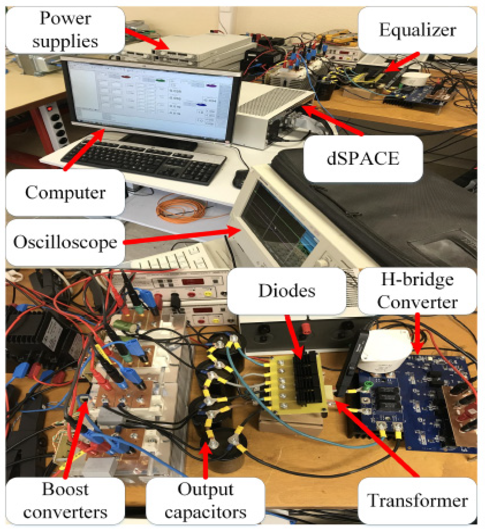
To verify the proposed system and validation of the theoretical analysis and the proposed control method, the experimental setup utilized for this work was constructed as shown in Figure 3. A dSPACE 1005 with the FPGA board was used to receive the captured data and send the commands. Four low-voltage, high-current programmable power supplies were utilized to simulate four PEMFCs. These power supplies were connected to four boost converters, and the output capacitors of the boosts were connected in series. The DC-bus voltage was well controlled at 48 V. The proposed balancing system connects to these capacitors. A planar transformer was built to implement the equalizer of the test bench. Each winding turn of this transformer means a printed circuit board. On each printed circuit board, a copper line with a width of 21.5 mm and a thickness of 35 μm was rotated in such a way that the circuits could be placed in the window of the magnetic core. This design was used to minimize leakage inductance. The switching frequency of the PEMFC converter and the equalizer was 20 kHz and 40 kHz, respectively. The parameters are given in Table 1.
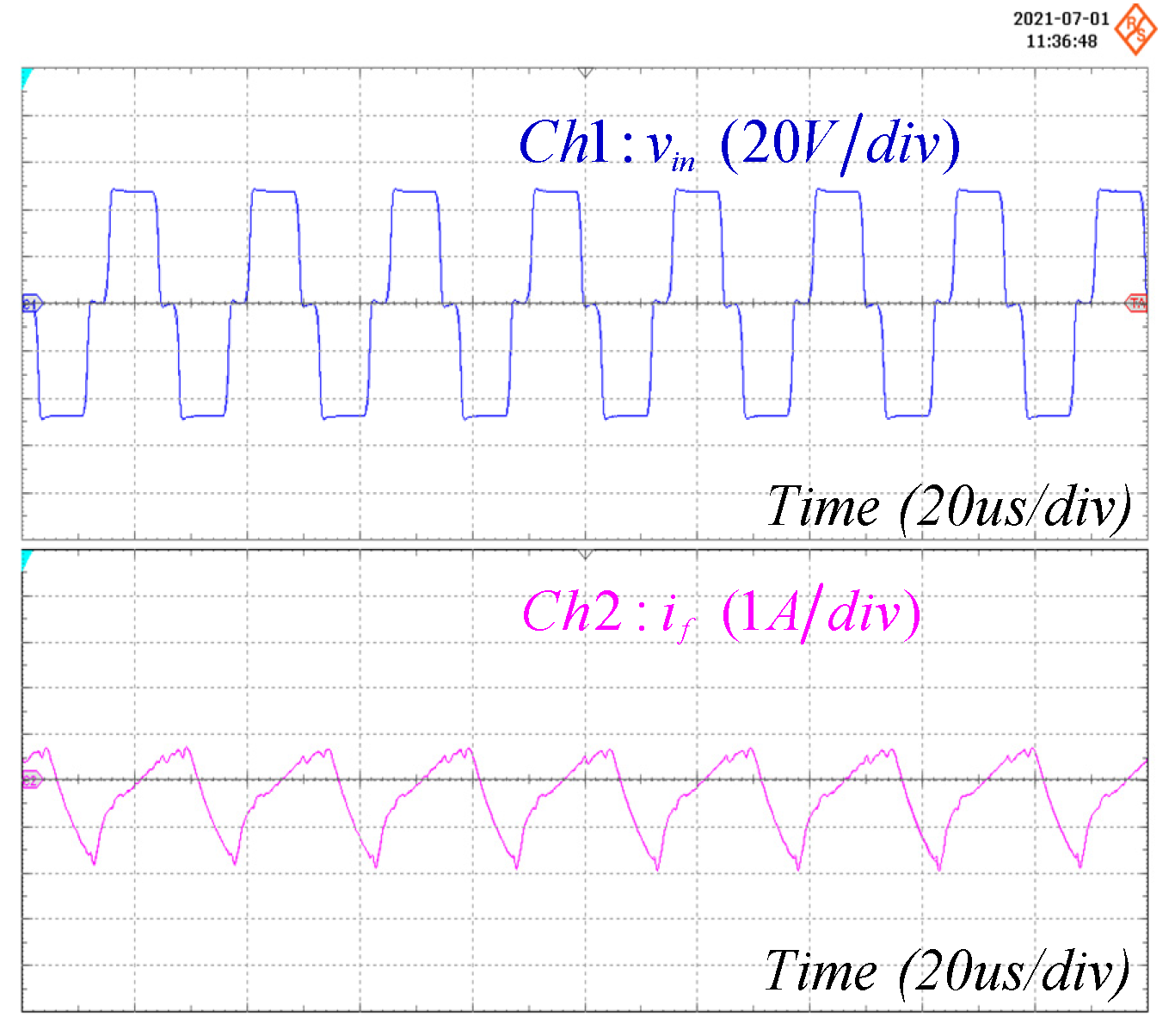
Firstly, different power reference PREFs were assigned to the 4 PEMFC stacks by the external energy management system. As shown in Figure 4, 63 W was assigned to the 1st PEMFC stack, and 126 W was assigned to the 2nd, 3rd and 4th PEMFC stacks. As shown in Figure 5, 63 W was assigned to the 1st and 2nd PEMFC stacks, and 126 W was assigned to the 3rd and 4th PEMFC stacks. As seen in Figure 5 and Figure 6, the equalizer can transfer energy back to the output of each converter via a high-frequency transformer, thus equalizing the voltage and ensuring the reliability and stability of the system.
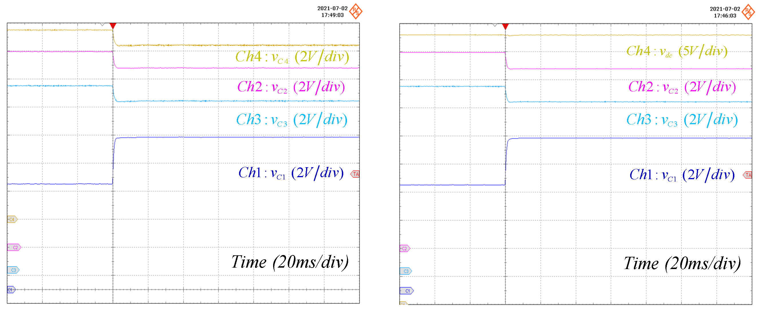
Moreover, Figure 6 and Figure 7 show the output voltages of the 4 DC–DC step-up converters, namely, vc1, vc2, vc3 and vc4, and the output voltage vdc. As shown in Figure 6, 63 W was assigned to the 1st PEMFC stack and 126 W to the 2nd, 3rd and 4th PEMFC stacks. As shown in Figure 7, 0 W was assigned to the 1st PEMFC stack and 126 W to the 2nd, 3rd and 4th PEMFC stacks. At the beginning of this test, the equalizer was not connected to the system, and after 60 ms, it was then connected. As can be seen, the equalizer ensures the stable operation of the system on the one hand and balances the output voltages of the four boost converters on the other hand, while their total output voltages remain constant.
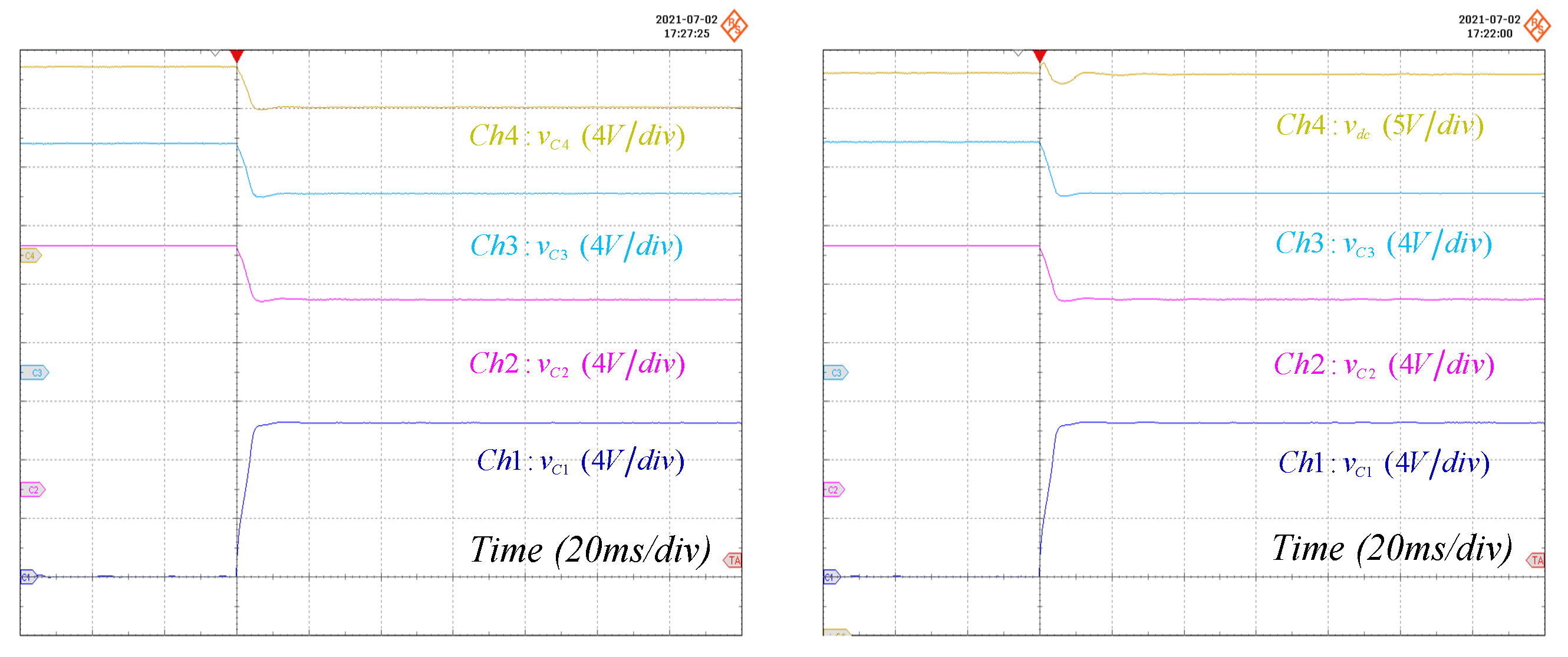
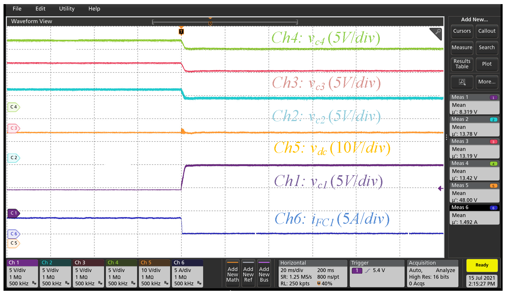
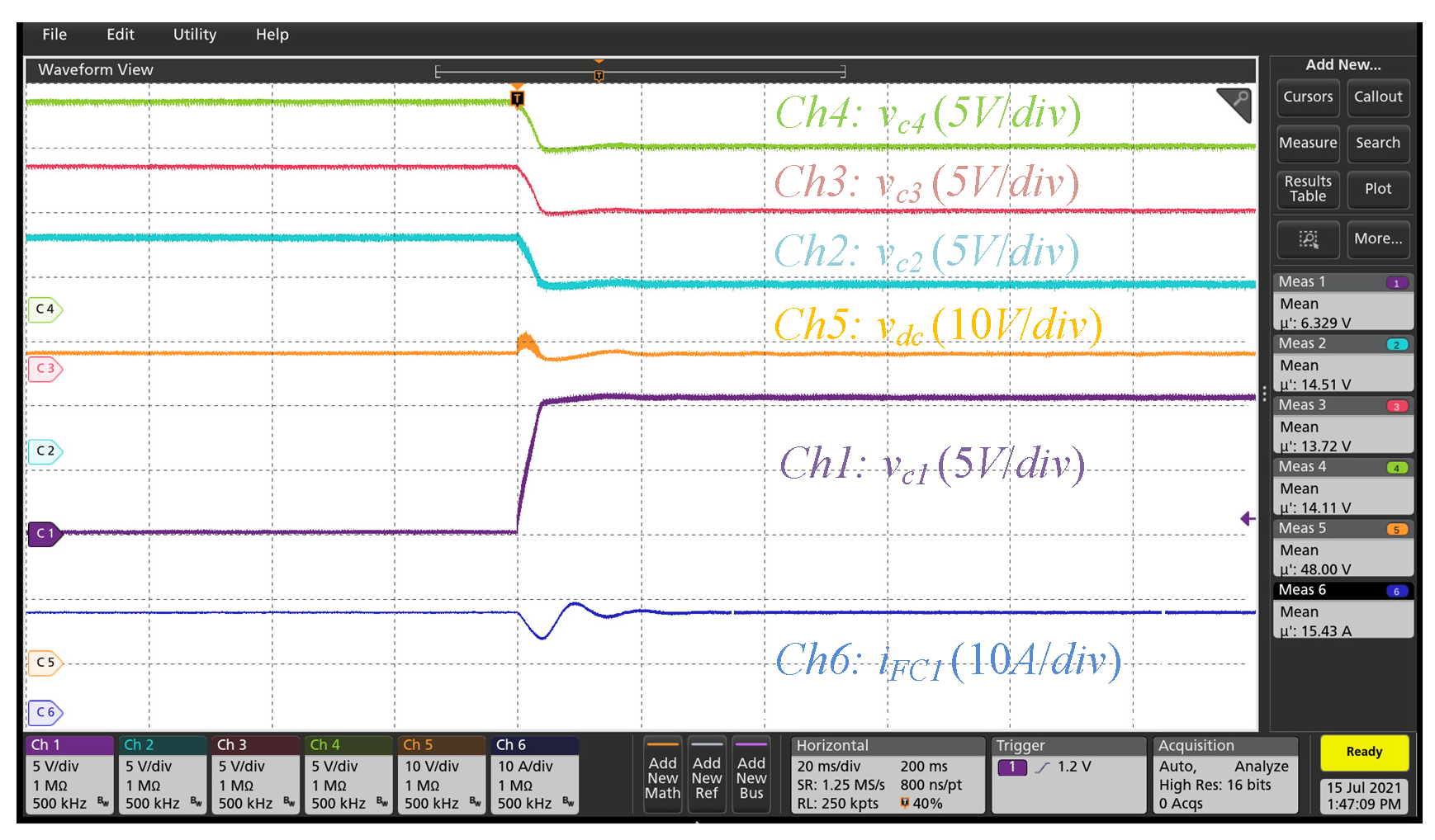
Next, Figure 8 gives the experimental waveforms of the 1st converter operating under an open-circuit situation, i.e., simulating the 1st PEMFC stack encountering a flooding fault. Figure 9 shows the experimental waveforms of the 1st boost converter operating under a short-circuit situation, when d = 1, i.e., simulating the 1st PEMFC stack encountering a drying fault. In Figure 8 and Figure 9, iFC1 is the inductor current of the 1st PEMFC boost converter. In Figure 8 and Figure 9, it can be seen that the system can operate and work well under membrane drying and flooding failure conditions with good transient and steady-state performance.
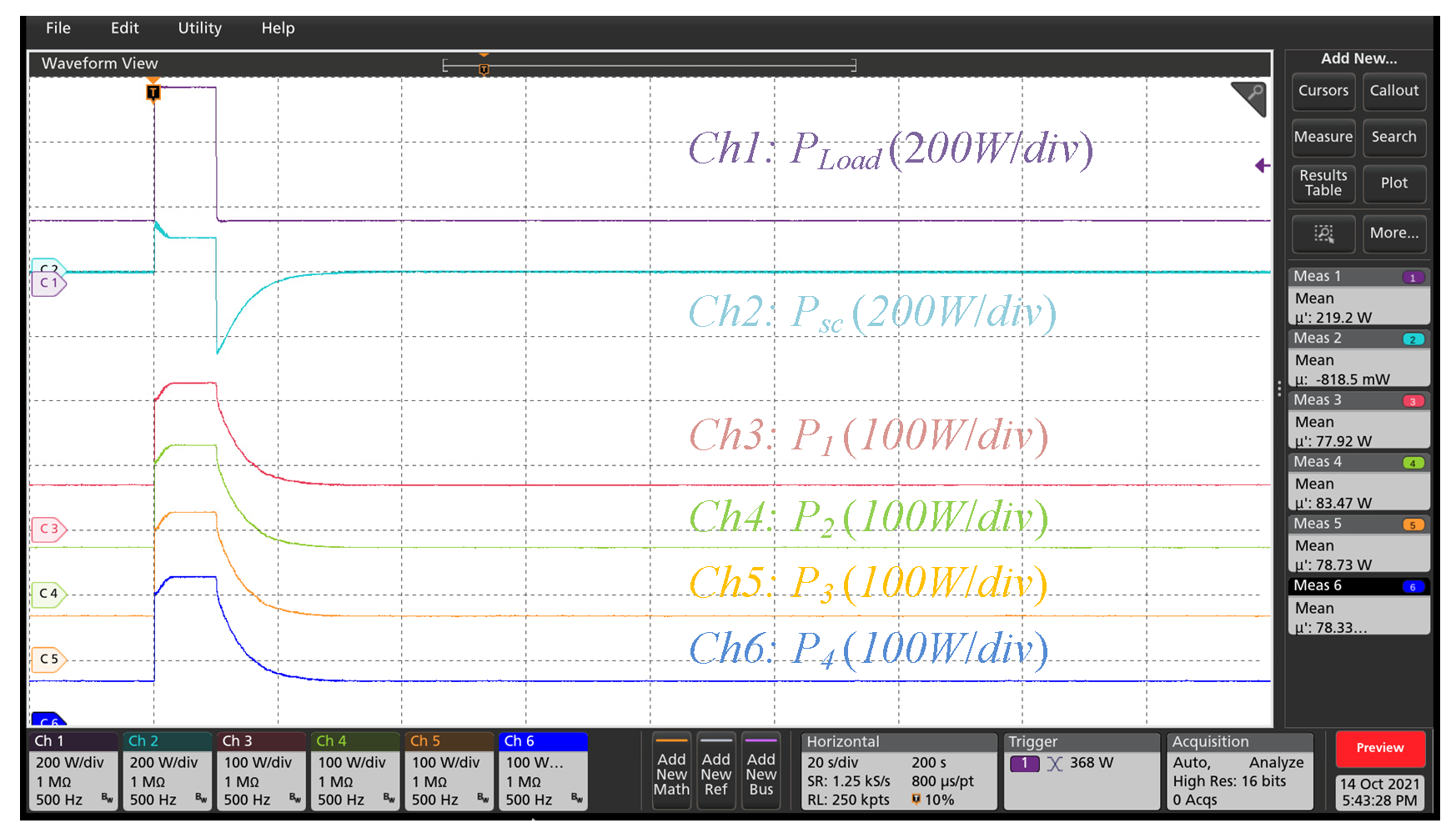
Finally, Figure 10 presents the experimental results during the load step. P1, P2, P3 and P4 are the output power of the 1st to 4th PEMFC stacks, respectively. PLoad and PSC are the load power and the supercapacitor power, respectively. The load power is held at 200 W in the beginning, increased instantaneously from 200 W to 600 W after 20 s, and then remains at 600 W for 10 s before returning instantaneously back to 200 W. As can be seen, the proposed control law can not only make the hybrid architecture have good dynamic characteristics but also guarantee the stability of the entire system. Thus, the experimental results verify the effectiveness and feasibility of the proposed control approach.

4. Conclusions

In this article, an AHBEC approach is proposed to control an input-parallel output-series DC–DC boost converter fed by PEMFCs using Hamiltonian and Lyapunov functions for electrified transport applications. In this control method, a built-in integrator is added to the Hamiltonian framework for controlling the system to remove the steady-state errors due to internal disturbances and external disturbances, and a Lyapunov-candidate function is used to demonstrate the large-signal stability of the power conversion system. To confirm the performance of the proposed control method, an experimental setup was built in the laboratory, and the proposed control algorithm was implemented in MicroLabBox. The experimental waveforms demonstrate the feasibility and effectiveness of the proposed energy-control strategy. Regarding future work, this paper has only designed the control of a multi-stack fuel cell system, not the battery system, and future work will control the whole system, including the control of the battery-side converter and even the converter of a hybrid battery and supercapacitor system, and will demonstrate the large-signal stabilization of the whole system.

Author Contributions

Conceptualization, S.P.; methodology, Y.L. and S.P.; formal analysis, Y.L. and S.P.; investigation, B.C. and S.P.; writing—original draft, Y.L. and S.P.; writing—review and editing, X.L., K.Z. and Z.M.; supervision, K.Z.; funding acquisition, X.L., S.P. and Z.M. All authors have read and agreed to the published version of the manuscript.

Funding

This work was supported by the National Natural Science Foundation of China (52307252 and 52202114).

Data Availability Statement

Data available on request subject to restrictions, e.g., privacy or ethical. The data presented in this study are available on request from the corresponding author. The data are not publicly available because they are necessary for forthcoming manuscript submissions and ongoing research projects.

Conflicts of Interest

The authors declare no conflict of interest.

Nomenclature

AHBECAdaptive Hamiltonian-Based Energy Control
PEMFC Proton-Exchange Membrane Fuel Cell
AIDA-PBCAdaptive Interconnection and Damping Assignment Passivity-Based Control
AHBECAdaptive Hamiltonian-Based Energy Control
PCHPort-Controlled Hamiltonian
H x Hamiltonian function
H d x Closed-loop Hamiltonian function
J , J d Interconnection matrix and desired interconnection matrix
R ,   R d Dissipation matrix and damping matrix
g c ,     g e Coefficient matrices in the PCH form
u ,     U e Input of the PCH form
y c ,     y e Output of the PCH form
x , x d The state variable and the desired equilibrium point of x .
v F C The output voltage of each fuel cell stack, i.e., v F C   = v F C 1   v F C 2   v F C 3   v F C 4 T
v C The output voltage of each fuel cell DC–DC converter, i.e., v c   =   v c 1   v c 2   v c 3   v c 4 T
i F C The output current of each fuel cell stack, i.e., i F C   = i F C 1   i F C 2 i F C 3   i F C 4 T
i d , v d The desired current and voltage of i F C   and   v C
C The   capacitance   of   each   DC DC   converter ,   C = C 1 = C 2 = C 3 = C 4
L The   inductance   of   each   DC DC   converter ,   L = L 1 = L 2 = L 3 = L 4
r L ,   r p The equivalent series/parallel resistance of each DC–DC converter

References

  1. Huangfu, Y.; Li, P.; Pang, S.; Tian, C.; Quan, S.; Zhang, Y.; Wei, J. An Improved Energy Management Strategy for Fuel Cell Hybrid Vehicles Based on the Pontryagin’s Minimum Principle. IEEE Trans. Ind. Appl. 2022, 58, 4086–4097. [Google Scholar] [CrossRef]
  2. Pang, S.; Nahid-Mobarakeh, B.; Pierfederici, S.; Huangfu, Y.; Luo, G.; Gao, F. Large-Signal Stable Nonlinear Control of DC/DC Power Converter with Online Estimation of Uncertainties. IEEE J. Emerg. Sel. Top. Power Electron. 2020, 9, 7355–7368. [Google Scholar] [CrossRef]
  3. Li, M.; Geng, H.; Zhang, X. Optimal Capacity Configuration of VSM-Controlled Grid-Connected Inverters in a Multi-Inverter System Based on Hybrid-Mode Control Under Weak Grids. In Proceedings of the 2021 IEEE Industry Applications Society Annual Meeting (IAS), Vancouver, BC, Canada, 10–14 October 2021; pp. 1–7. [Google Scholar]
  4. Pang, S.; Bahrami, M.; Martin, J.-P.; Pierfederici, S.; Huangfu, Y.; Nahid-Mobarakeh, B. Hamiltonian Energy Control with Built-in Integral Term for Fuel Cell Hybrid Power System. In Proceedings of the 2022 IEEE Industry Applications Society Annual Meeting (IAS), Detroit, MI, USA, 9–14 October 2022; pp. 1–6. [Google Scholar]
  5. Turkmen, A.C.; Solmaz, S.; Celik, C. Analysis of fuel cell vehicles with advisor software. Renew. Sustain. Energy Rev. 2017, 70, 1066–1071. [Google Scholar] [CrossRef]
  6. Bizon, N.; Thounthong, P.; Guilbert, D. Efficient Operation of the Hybrid Power System Using an Optimal Fueling Strategy and Control of the Fuel Cell Power Based on the Required Power Tracking Algorithm. Sustainability 2020, 12, 9690. [Google Scholar] [CrossRef]
  7. Pang, S.; Nahid-Mobarakeh, B.; Pierfederici, S.; Huangfu, Y.; Luo, G.; Gao, F. Fault-tolerant consideration and active stabilization for floating interleaved boost converter system. In Proceedings of the IECON 2017—43rd Annual Conference of the IEEE Industrial Electronics Society, Beijing, China, 29 October–1 November 2017; pp. 7947–7952. [Google Scholar]
  8. Bahrami, M.; Martin, J.-P.; Maranzana, G.; Pierfederici, S.; Weber, M.; Meibody-Tabar, F.; Zandi, M. Multi-Stack Lifetime Improvement through Adapted Power Electronic Architecture in a Fuel Cell Hybrid System. Mathematics 2020, 8, 739. [Google Scholar] [CrossRef]
  9. Pang, S.; Nahid-Mobarakeh, B.; Pierfederici, S.; Phattanasak, M.; Huangfu, Y.; Luo, G.; Gao, F. Interconnection and Damping Assignment Passivity-Based Control Applied to On-Board DC–DC Power Converter System Supplying Constant Power Load. IEEE Trans. Ind. Appl. 2019, 55, 6476–6485. [Google Scholar] [CrossRef]
  10. Pang, S.; Nahid-Mobarakeh, B.; Pierfederici, S.; Huangfu, Y.; Luo, G.; Gao, F. Toward Stabilization of Constant Power Loads Using IDA-PBC for Cascaded LC Filter DC/DC Converters. IEEE J. Emerg. Sel. Top. Power Electron. 2019, 9, 1302–1314. [Google Scholar] [CrossRef]
  11. Yang, Z.; Zha, X. Stabilization Method of Islanded DC Microgrid Based on the Exact Feedback Linearization. In Proceedings of the 2015 4th National Conference on Electrical, Electronics and Computer Engineering, Xi’an, China, 12–13 December 2015; Atlantis Press: Amsterdam, The Netherlands, 2015; pp. 781–787. [Google Scholar]
  12. Singh, S.; Fulwani, D.; Kumar, V. Robust sliding-mode control of dc/dc boost converter feeding a constant power load. IET Power Electron. 2015, 8, 1230–1237. [Google Scholar] [CrossRef]
  13. Yuan, C.; Bai, H.; Ma, R.; Huangfu, Y. Large-Signal Stability Analysis and Design of Finite-Time Controller for the Electric Vehicle DC Power System. IEEE Trans. Ind. Appl. 2021, 58, 868–878. [Google Scholar] [CrossRef]
  14. Liu, Y.; Hu, Y.; Wang, Y.; Chau, T.K.; Zhang, X.; Iu, H.H.; Fernando, T. A Novel Adaptive Model Predictive Control for Proton Exchange Membrane Fuel Cell in DC Microgrids. IEEE Trans. Smart Grid 2022, 13, 1801–1812. [Google Scholar] [CrossRef]
  15. Siffat, S.A.; Ahmad, I.; Rahman, A.U.; Islam, Y. Robust Integral Backstepping Control for Unified Model of Hybrid Electric Vehicles. IEEE Access 2020, 8, 49038–49052. [Google Scholar] [CrossRef]
  16. Steckler, P.-B.; Gauthier, J.-Y.; Lin-Shi, X.; Wallart, F. Differential Flatness-Based, Full-Order Nonlinear Control of a Modular Multilevel Converter (MMC). IEEE Trans. Control. Syst. Technol. 2021, 30, 547–557. [Google Scholar] [CrossRef]
  17. Gil-Antonio, L.; Saldivar, B.; Portillo-Rodriguez, O.; Vazquez-Guzman, G.; De Oca-Armeaga, S.M. Trajectory Tracking Control for a Boost Converter Based on the Differential Flatness Property. IEEE Access 2019, 7, 63437–63446. [Google Scholar] [CrossRef]
  18. Bahrami, M.; Martin, J.-P.; Maranzana, G.; Pierfederici, S.; Weber, M.; Meibody-Tabar, F.; Zandi, M. Design and Modeling of an Equalizer for Fuel Cell Energy Management Systems. IEEE Trans. Power Electron. 2019, 34, 10925–10935. [Google Scholar] [CrossRef]
  19. Pang, S.; Nahid-Mobarakeh, B.; Hashjin, S.A.; Pierfederici, S.; Martin, J.-P.; Liu, Y.; Huangfu, Y.; Luo, G.; Gao, F. Stability Improvement of Cascaded Power Conversion Systems Based on Hamiltonian Energy Control Theory. IEEE Trans. Ind. Appl. 2021, 57, 1081–1093. [Google Scholar] [CrossRef]
  20. Thounthong, P.; Mungporn, P.; Pierfederici, S.; Guilbert, D.; Takorabet, N.; Nahid-Mobarakeh, B.; Hu, Y.; Bizon, N.; Huangfu, Y.; Kumam, P.; et al. Robust Hamiltonian Energy Control Based on Lyapunov Function for Four-Phase Parallel Fuel Cell Boost Converter for DC Microgrid Applications. IEEE Trans. Sustain. Energy 2021, 12, 1500–1511. [Google Scholar] [CrossRef]
  21. Lapique, M.; Pang, S.; Martin, J.-P.; Pierfederici, S.; Weber, M.; Zaim, S. Enhanced IDA-PBC Applied to a Three-Phase PWM Rectifier for Stable Interfacing Between AC and DC Microgrids Embedded in More Electrical Aircraft. IEEE Trans. Ind. Electron. 2022, 70, 995–1004. [Google Scholar] [CrossRef]
  22. Pang, S.; Mao, Z.; Li, X.; Huangfu, Y.; Bahrami, M.; Martin, J.-P.; Pierfederici, S.; Nahid-Mobarakeh, B. Hamiltonian Energy Control with Energy Management Strategy for Fuel Cell Hybrid Power System. IEEE Trans. Ind. Appl. 2023, 59, 7716–7724. [Google Scholar] [CrossRef]
  23. Huang, M.; Zhang, Z.; Chen, F.; Wu, W.; Yao, Z.; Blaabjerg, F. Stabilization Design of Three-Phase LCL-Filtered Grid-Connected Inverter Using IDA-PBC Controller. Int. Trans. Electr. Energy Syst. 2022, 2022, 7515321. [Google Scholar] [CrossRef]
  24. Lin, G.; Liu, J.; Rehtanz, C.; Li, Y.; Zuo, W.; Wang, P. Analysis of instability causes in the bi-dc converter and enhancing its performance by improving the damping in the IDA-PBC control. IET Gener. Transm. Distrib. 2021, 15, 2411–2421. [Google Scholar] [CrossRef]
  25. Benmouna, A.; Becherif, M.; Boulon, L.; Dépature, C.; Ramadan, H.S. Efficient experimental energy management operating for FC/battery/SC vehicles via hybrid Artificial Neural Networks-Passivity Based Control. Renew. Energy 2021, 178, 1291–1302. [Google Scholar] [CrossRef]
  26. Pang, S.; Hashjin, S.A.; Nahid-Mobarakeh, B.; Pierfederici, S.; Huangfu, Y.; Luo, G.; Gao, F. Large-Signal Stabilization of Power Converters Cascaded Input Filter Using Adaptive Energy Shaping Control. IEEE Trans. Transp. Electrif. 2020, 7, 838–853. [Google Scholar] [CrossRef]
  27. Thounthong, P.; Mungporn, P.; Nahid-Mobarakeh, B.; Bizon, N.; Pierfederici, S.; Guilbert, D. Improved Adaptive Hamiltonian Control Law for Constant Power Load Stability Issue in DC Microgrid: Case Study for Multiphase Interleaved Fuel Cell Boost Converter. Sustainability 2021, 13, 8093. [Google Scholar] [CrossRef]
  28. Wang, M.; Tang, F.; Wu, X.; Niu, J.; Zhang, Y.; Wang, J. A Nonlinear Control Strategy for DC-DC Converter with Unknown Constant Power Load Using Damping and Interconnection Injecting. Energies 2021, 14, 3031. [Google Scholar] [CrossRef]
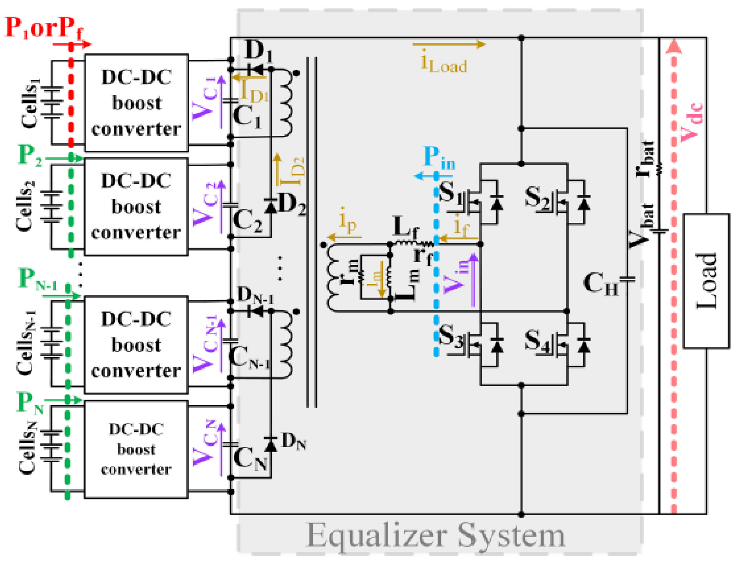
Figure 1. The studied power-conversion architecture of the hybrid PEMFC system.
Energies 16 07855 g001
Figure 2. Topology of the individual DC–DC boost converter.
Energies 16 07855 g002
Figure 3. Experimental setup.
Energies 16 07855 g003
Figure 4. Experimental waveforms of the equalizer while the 1st reference power is 63 W; the 2nd, 3rd and 4th reference powers are 126 W.
Energies 16 07855 g004
Figure 5. Experimental waveforms of the equalizer while the 1st and 2nd reference powers are 63 W, the 3rd and 4th reference powers are 126 W.
Energies 16 07855 g005
Figure 6. Experimental waveforms of voltages while the 1st reference power is 63 W; the 2nd, 3rd and 4th reference powers are 126 W.
Energies 16 07855 g006
Figure 7. Experimental waveforms of voltages while the 1st reference power is 0 W; the 2nd, 3rd and 4th reference powers are 126 W.
Energies 16 07855 g007
Figure 8. Experimental waveforms while the 1st step-up converter is working in open-circuit situation.
Energies 16 07855 g008
Figure 9. Experimental waveforms while the 1st step-up converter is working in short-circuit situation.
Energies 16 07855 g009
Figure 10. Experimental results while the load is increased from 200 W to 600 W, maintained for 10 s, and then returned to 200 W.
Energies 16 07855 g010
Table 1. System parameters.
SymbolQuantityNominal Value
vcOutput voltage of each fuel cell converter12 V
LDC–DC converter inductance200 μH
rLDC–DC converter inductor resistance0.02 Ω
CDC–DC converter capacitance4700 μF
rpDC–DC converter capacitor insulation resistance5 MΩ
FsFrequency20/40 kHz
KIControl parameter10
Disclaimer/Publisher’s Note: The statements, opinions and data contained in all publications are solely those of the individual author(s) and contributor(s) and not of MDPI and/or the editor(s). MDPI and/or the editor(s) disclaim responsibility for any injury to people or property resulting from any ideas, methods, instructions or products referred to in the content.