Article

Electromagnetic Performance Analysis of a Multichannel Permanent Magnet Synchronous Generator †

1
Department of Electrodynamics and Electrical Machine Systems, Rzeszow University of Technology, 35-959 Rzeszow, Poland
2
Department of Power Electronics and Power Engineering, Rzeszow University of Technology, 35-959 Rzeszow, Poland
*
Author to whom correspondence should be addressed.
The publication is an extended version of the article presented at the conference Selected Issues in Power Engineering, Electrical Engineering and Industry 4.0, Rzeszów, Poland, 30 November 2022.
Energies 2023, 16(23), 7816; https://doi.org/10.3390/en16237816
Submission received: 22 October 2023 / Revised: 22 November 2023 / Accepted: 24 November 2023 / Published: 28 November 2023
(This article belongs to the Topic Advanced Electrical Machines and Drives Technologies)

Abstract

:
In this paper, we present an analysis of the properties of the prototype three-phase Multichannel Permanent Magnet Synchronous Generator (MCPMSG) prototype designed and constructed by the authors. Each channel of the generator has electrically separated windings, which allows us to create an island system of electricity generation. The analyzed MCPMSG is intended for critical applications, and it is designed for four-channel operation. The purpose of this work is to analyze various configurations of the generator channels to improve the redundancy of the electricity generation system. The MCPMSG operation with one or two independent sources of energy consumption in the case of a dual-channel or double dual-channel operation was investigated. For the analyzed cases, the original mathematical models of the three-phase MCPMSG were developed. On the basis of numerical and laboratory tests, the influence of individual configurations on the MCPMSG output parameters was determined. An original method for diagnosing the operation of the MCPMSG channels was developed. Numerical and laboratory tests of the proposed diagnostic method based on a single voltage signal were carried out. As part of the laboratory tests, selected operating states under conditions of full winding symmetry and internal asymmetry were analyzed. The advantage of the proposed diagnostic method is the control of the operating state of the channels both under load and in the de-energized state. The proposed diagnostic method for control of the individual channel requires measurement of only one voltage signal.

1. Introduction

The use of fault-tolerant electric systems becomes unavoidable in many critical applications where failures may endanger the safety of the user or machine. Therefore, it is essential to develop structures that are resistant to damage and capable of maintaining continuity of operation. Such solutions can be achieved by redundancy of system components, for example, a multichannel three-phase system, multiple independent power converters, etc. Although multiplying components may generate higher cost, it is worth it in terms of safety.
Multichannel machines are investigated in various areas such as aviation (More Electric Aircraft—MEA) [1,2,3], the automotive industry (Electric Vehicles—EVs) [4,5,6], the marine industry [7], renewable energy resources (RESs) [8,9,10,11,12], and military applications [2]. In the literature, the MEA concept is the most popular in regard to multichannel machines.
An overview of electricity generation in aviation is widely presented in [2]. The authors indicate that electric power systems are progressively replacing pneumatic, hydraulic, and mechanical power systems in MEA. Therefore, there is a need for on-board electric power generation. Over the years, reliability and power density have become more critical parameters. In [13], it is mentioned that the Permanent Magnet Synchronous Generator (PMSG) is a primary power source for modern aircraft, both civilian (Airbus and Boeing) and military (Lockheed Martin). Since the complexity of the on-board power system and its load are high, the Permanent Magnet Synchronous Machine (PMSM) is the most suitable due to its good airworthiness, autonomous work, high power density, and robust design. The authors of [1] also suggest that a favored choice for MEA applications is a dual or triple three-phase PMSM due to its balance between redundancy and complexity, while providing a balanced operation after a failure occurs. In addition to MEA, there are papers that consider the multichannel operation of EVs, since it is also essential to provide high reliability to both users and machines in the automotive field [4,5].
In addition to reliability and safety, ecology is also an essential aspect, as many countries are committed to reducing the emission of greenhouse gases [8,10,12]. In the scientific literature, tremendous work has been conducted on the development of a reduction in gas emissions and fuel cost in MEA [3]. The reduction in air pollution and the exhaustion of petroleum resources is also investigated in the area of EVs [6]. In terms of RESs, the authors focus mainly on wind power generation [9,11,12]. Recently, interest in generating energy from the movement of marine waves or marine currents, which is in an early stage of development, has been observed. Therefore, generators for use in the marine industry are investigated [7,8].
So far, a multichannel generator has not been widely investigated. There are a few papers on dual-channel generators or motors [4,5,8,9,10,14,15,16,17]. The tests performed refer to dual-channel work under normal conditions [4,7,8,9,10,11,12,13,18,19] and include failures, such as operation during failure of one or both channels [5,14], short circuit [9,18], and open circuit [4]. The starter/generator system [3,18,20] is also investigated.
Researchers have analyzed reluctance generators [14,16,17], brushless DC motors with permanent magnets [5,15], and PMSMs [4,7,8,9,10,11,12,13,18,19] in terms of multichannel operation. Recently, the type of generator that has been the most researched is the PMSG. Many authors in their work indicate that the PMSM is generally the preferred choice (over reluctance and induction machines) for various applications, because of its high power density, high efficiency, compact volume, and low maintenance costs, among others. Although the PMSMs have a lot of advantages, they are challenging in terms of reactive power, parallel operation, and fault tolerance [2]. In [1], it is said that in the PMSM, currents can flow in a failed lane even if it is disconnected from the power supply due to the presence of magnet-induced electromotive force (EMF). In such a case, at the design stage of the machine, the effects of a potential short circuit in the winding should be minimized by introducing, for example, thermal separation of the windings or increasing the hardiness of permanent magnets to the appearance of such a machine operating condition.
The diagnosis of generator operation and malfunctions is another important issue. There are different methods of diagnostics in terms of electric machines, and therefore, different diagnostic parameters can be used, for example, electric current, voltage, signal, temperature, noise, vibration, etc. [21,22,23,24,25]. Harmonic analysis can, for example, provide information on the presence of anomalies in generator operation.
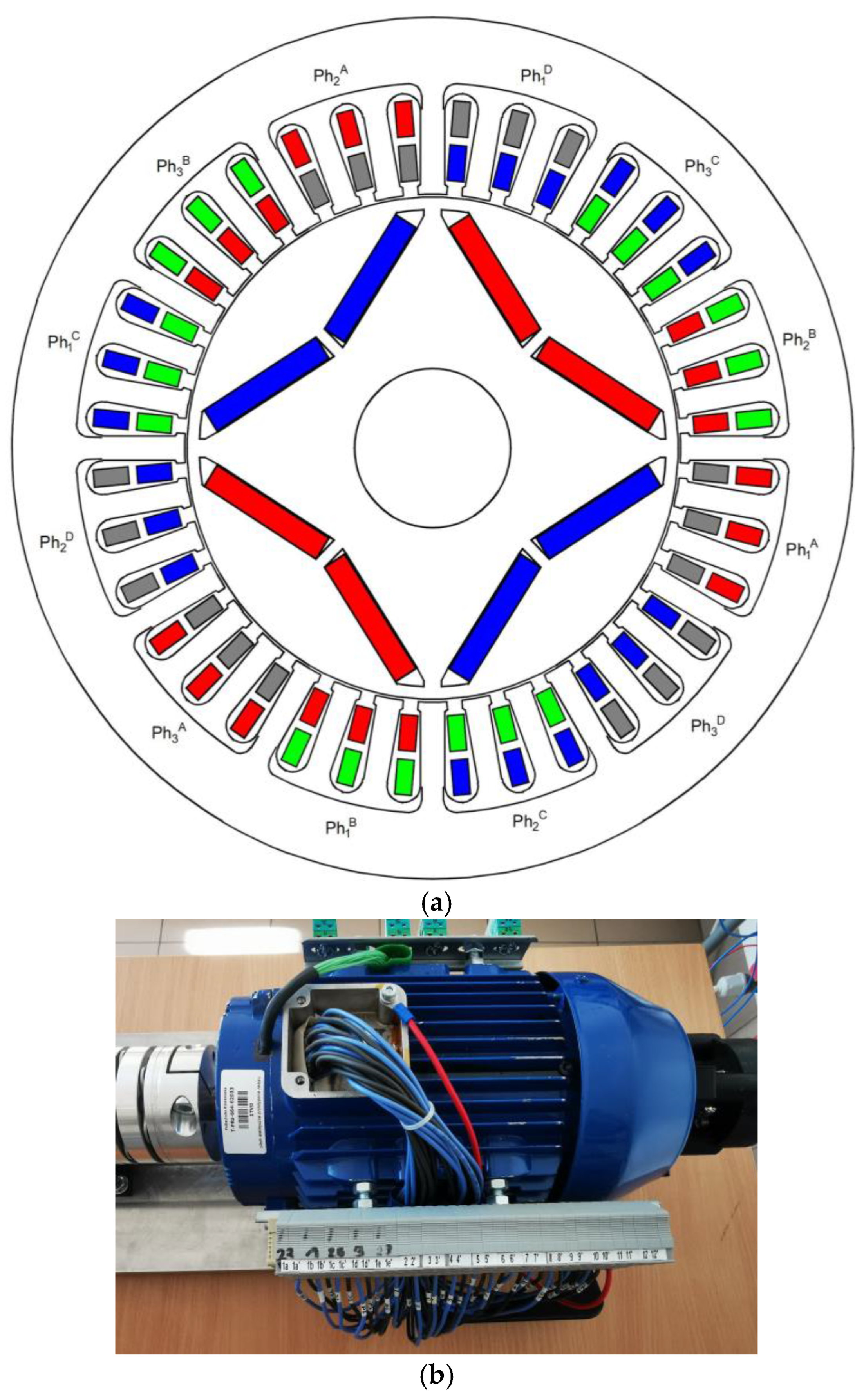
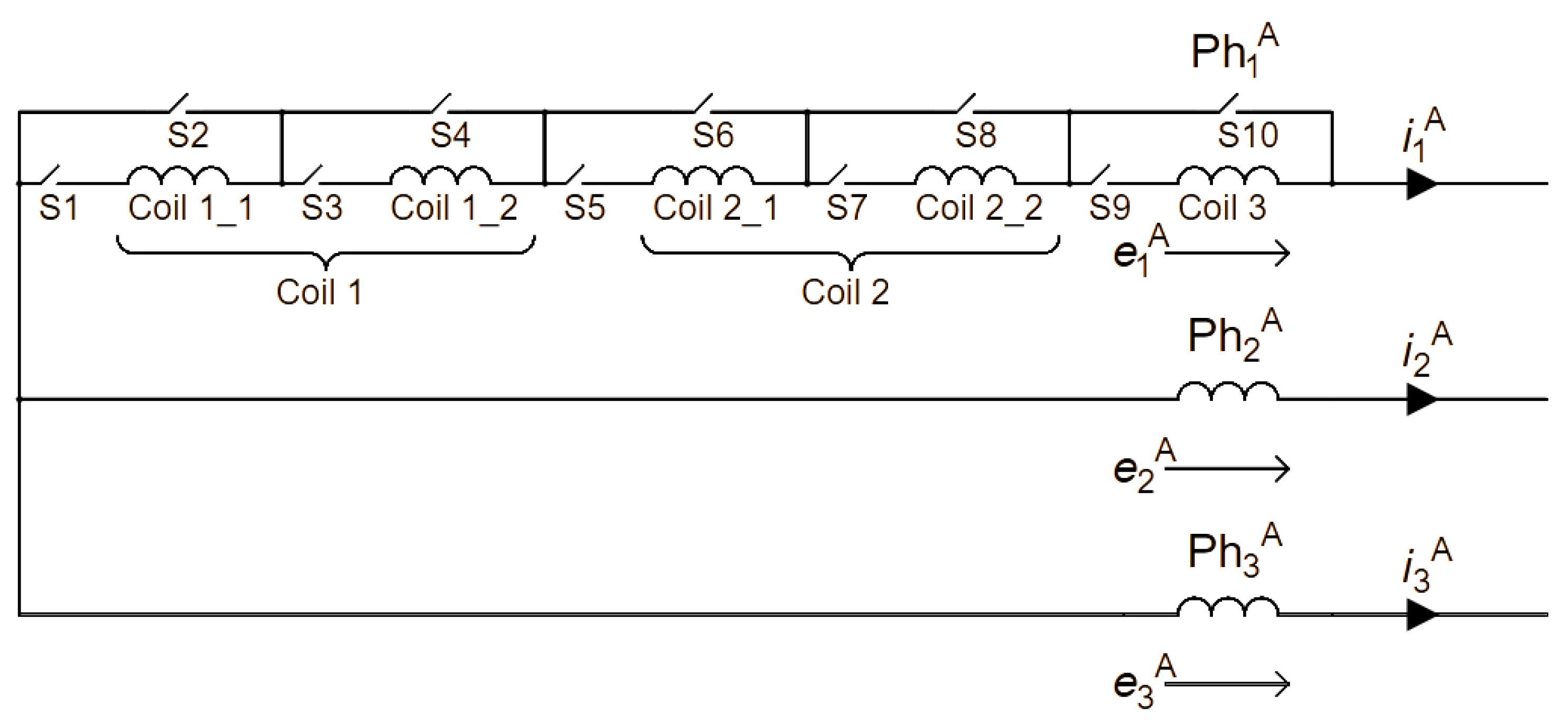
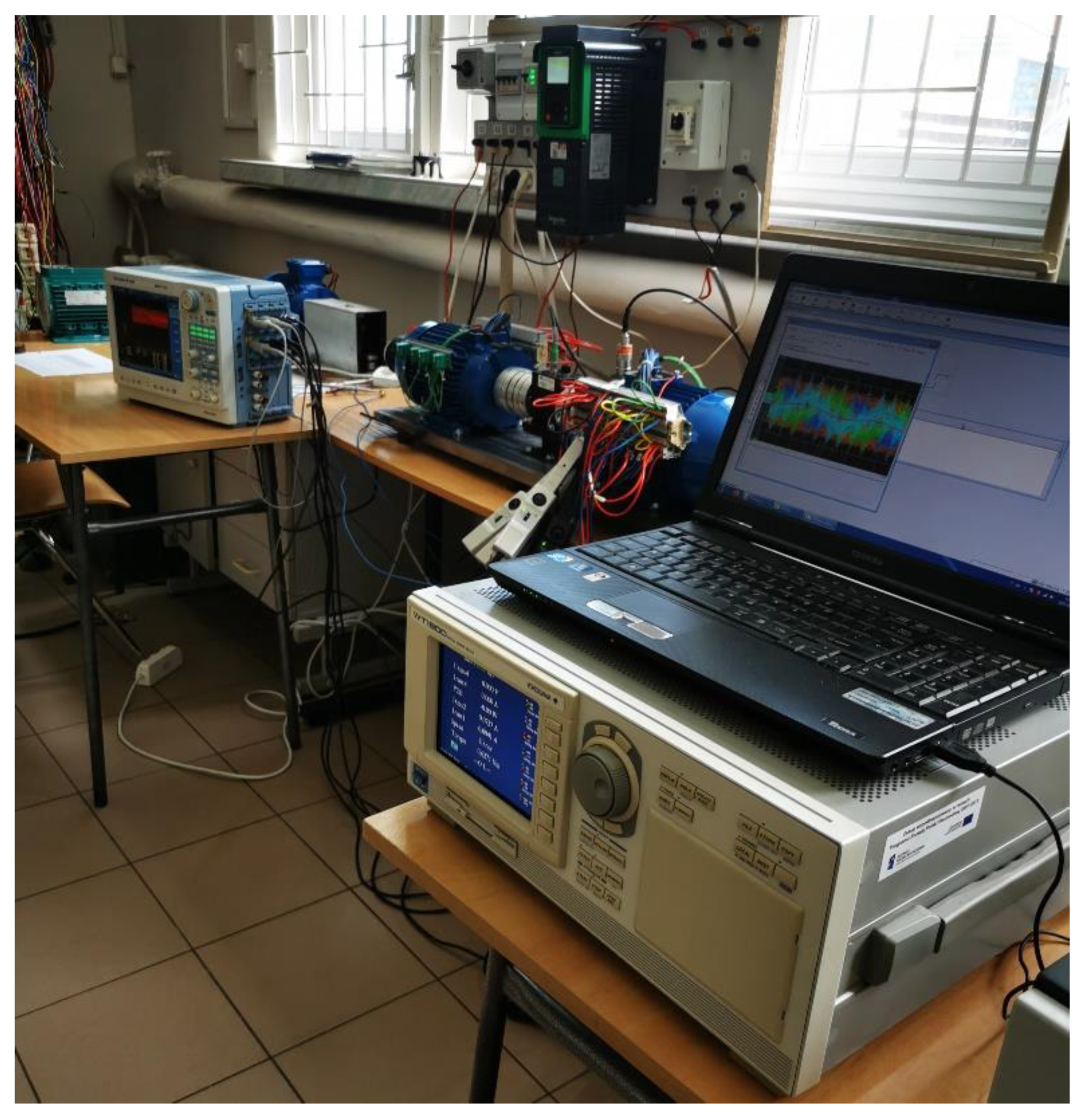
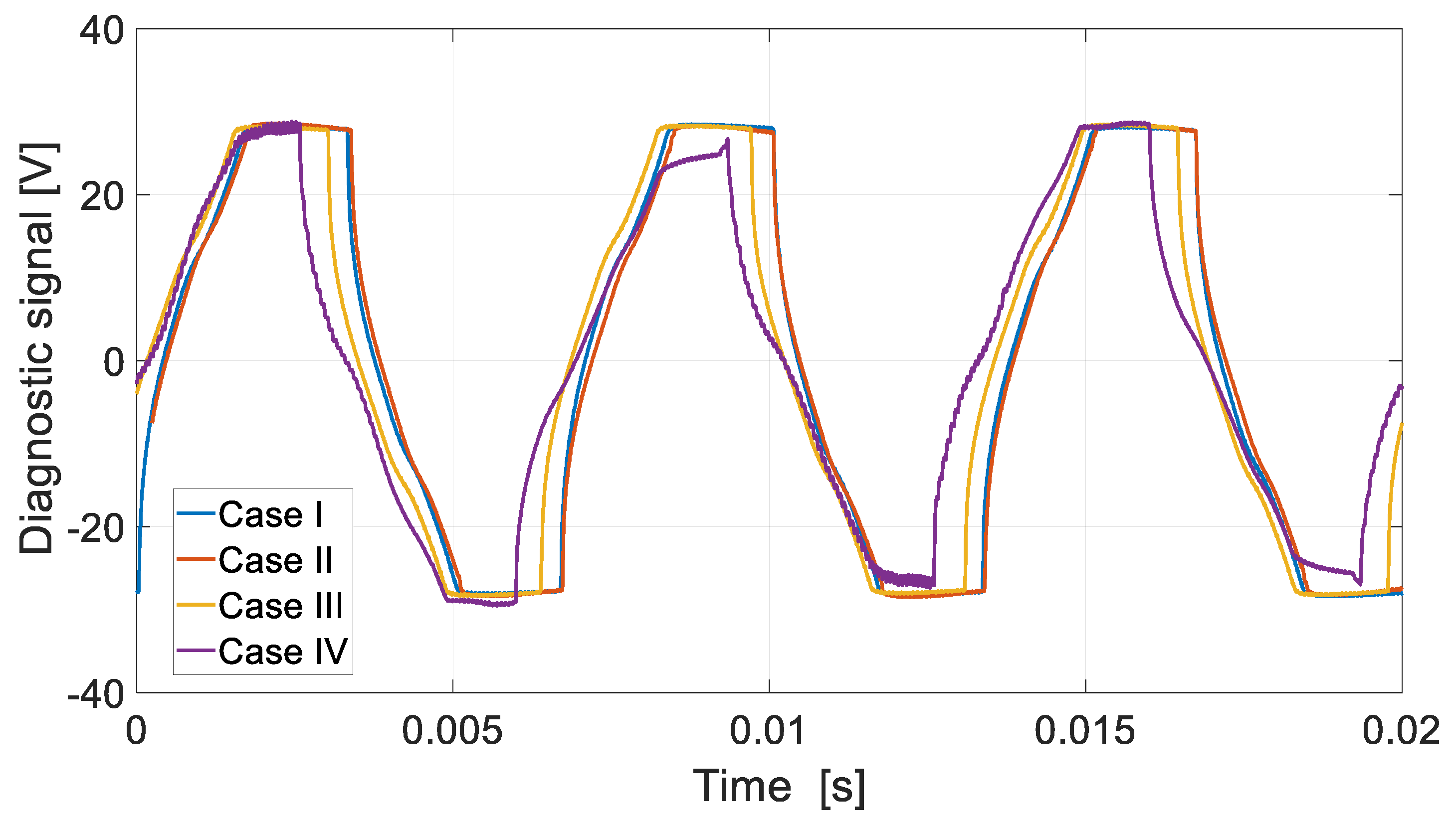
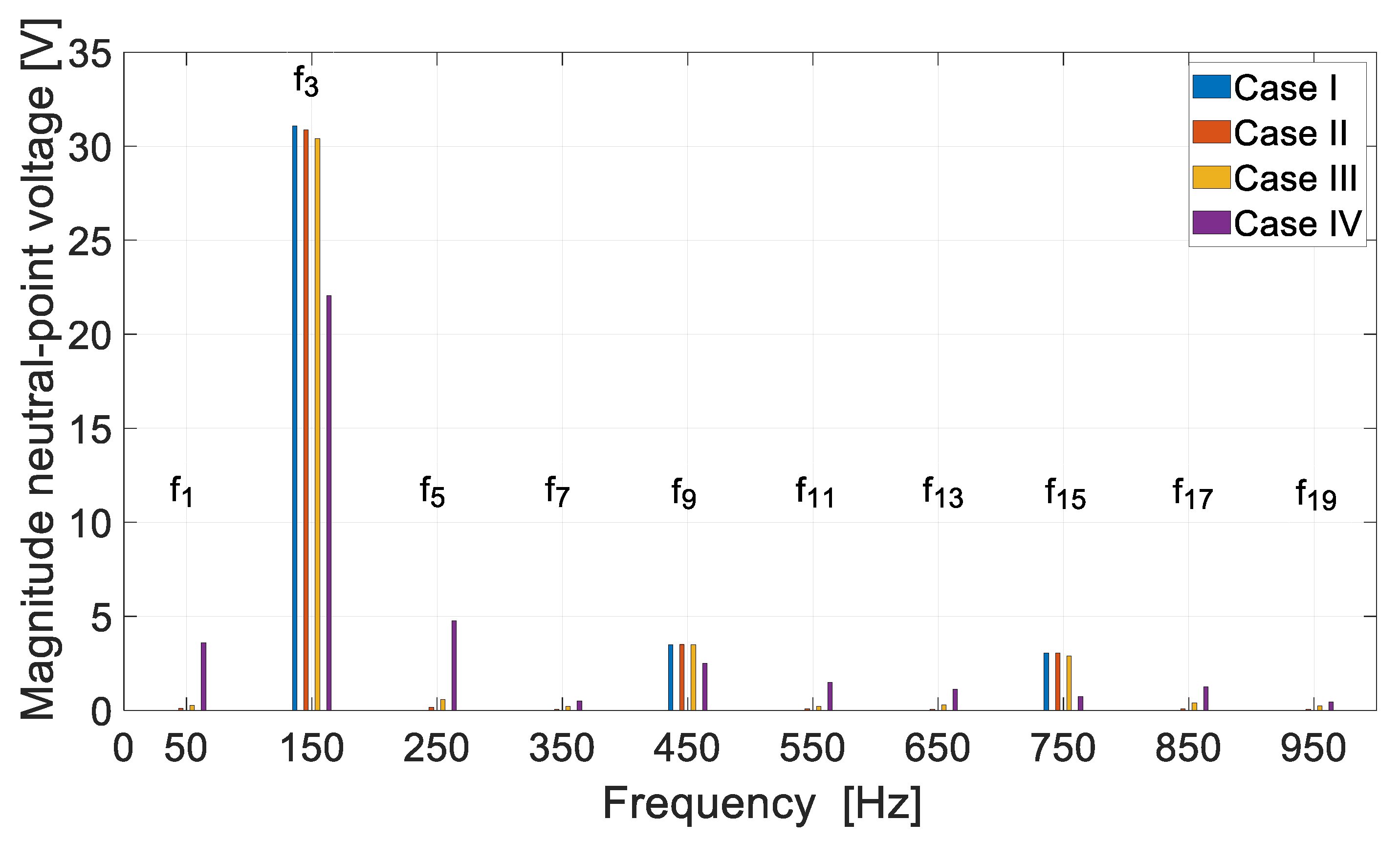
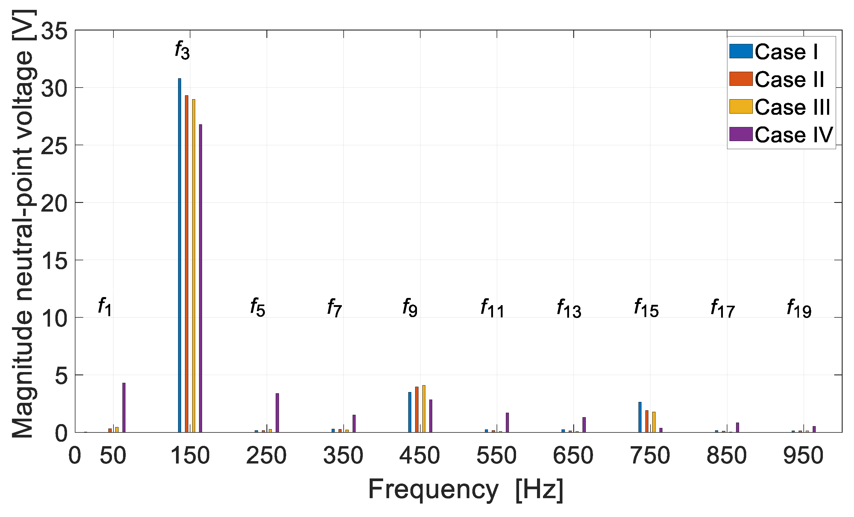
The aim of this work is to analyze properties of the prototype Multichannel Permanent Magnet Synchronous Generator (MCPMSG) prototype designed and constructed by the authors for critical applications. Various configurations of the generator channels, taking into account the improvement of the redundancy of the electricity generation system, were analyzed. There are few works on the MCPMSG. Furthermore, the existing works do not address the subject of the influence of the channel configuration on the MCPMSG properties. An original mathematical model was developed for the study of the MCPMSG operation. Under laboratory conditions, the influence of the channel configuration on the output parameters of the MCPMSG was verified. An original method for diagnosing the operation of individual channels of the MCPMSG was proposed by the authors. This diagnostic method based on a single voltage signal was tested under the conditions of numerical tests and laboratory tests. As part of these tests of the proposed diagnostic method, the capabilities of the prototype MCPMSG were used to analyze selected operating states of internal asymmetry. The advantage of the proposed diagnostic method is the control of the operating state of the channels both under load and in the de-energized state. The proposed diagnostic method for control of the individual channel requires measurement of only one voltage signal.
The paper consists of several sections. In Section 2, design and configuration analysis of the MCPMSG is presented. Section 3 contains the mathematical model of the tested MCPMSG. The operation of the MCPMSG with different sources of energy consumption is presented in Section 4. In Section 5, the proposed diagnostic method for the MCPMSG is discussed. The final Section 6 contains a summary and conclusions.

2. Design and Configuration Analysis of MCPMSG

2.1. Analysis of the MCPMSG

The designed and constructed MCPMSG is a demonstrator for testing multichannel operation. It is not optimized in terms of, for example, obtaining maximum efficiency. To reduce the cost of the prototype, components of a commercial three-phase squirrel-cage induction motor with a power of 1.5 kW were used (all components except the rotor magnetic circuit). The possibility of testing internal asymmetries, e.g., short circuits, and the introduction of temperature sensors in each phase of each channel (12 sensors) reduced the slot filling factor. The biggest drawback of the demonstrator is the use of solid steel in the magnetic circuit of the rotor instead of a package of magnetic sheets. The analyzed structure of the MCPMSG was designed to work with four independent channels. They are conventionally named A, B, C, and D. Each channel consists of three-phase windings. There are no electrical displacements between the channels, which gives much more flexibility in their configuration. However, a certain increase in the ripple of the generated braking torque is a cost of this solution. A cross-section of the geometry of the analyzed generator with locations of the windings of individual channels and prototype is shown in Figure 1. Each channel is marked with a different color.
Table 1 presents selected parameters of the analyzed MCPMSG.
In the analyzed MCPMSG system, it is possible to operate in a mode of:
  • QCO (quad-channel operation);
  • TCO (triple-channel operation);
  • DDCO (double dual-channel operation);
  • DCO (dual-channel operation);
  • SCO (single-channel operation).
A high safety factor in relation to the power output during the design of the machine was included. This is important in aviation or military applications [1,2].
While designing the generator, tests under unusual operating conditions were foreseen. In one of the phases of channel A, it is possible to change the number of turns of the coil within a certain range. In Figure 2, a winding connection of channel A is presented. It allows testing related to the operation of the generator under conditions of internal asymmetry to be tested. In addition, in each phase of the channel, thermocouples were installed to control the thermal condition of the machine.
Different operating states can be achieved depending on the configuration of phase 1 in channel A. Selected states analyzed in the MCPMSG are presented in Table 2.
The variant named Case I means the operating state under the condition of electric and magnetic symmetry. The remaining variants introduce electric and magnetic asymmetry. Case II means the operating state with the lack of one turn of the coil in the winding of the generator. Case III includes the lack of three turns in the coil in the winding. A relatively insignificant asymmetry can be observed for Case II. In Case III, there is a slightly greater internal asymmetry. In Case IV, the phase winding contains only two coils (lack of 28 turns of the coil).
In the analyzed Case I (Table 2), the induced voltages in the tested MCPMSG (Figure 1a) are the same in each channel. In practice, these voltages may slightly differ. In Figure 3, an exemplary phase EMF of one of the channels obtained from the numerical model (speed at 1500 rpm) is presented (signed as “num”). Additionally, the phase EMF of phase 1 of each channel is also presented in Figure 3.
Good agreement is obtained between the results of numerical calculations and the laboratory tests. The received RMS (root mean square) values received from the phase EMF of the tested generator at the speed of 1500 rpm are listed in Table 3.
Slight differences in the phase EMF waveforms of individual channels can be observed in the experiment results. This is a typical result for any prototype made. Even relatively small changes in the arrangement of the turns in the slots affect the value of the induced voltage. This is definitely more visible in the MCPMSG than in the classical machine with, for example, serial connection of groups of turns. It has a negative impact on the operation of the multichannel generator working in DCO, TCO, and QCO modes. The highest-value EMF occurs in phase 1 of the channel A. In this channel, additional outputs of two coils have been made (Figure 2). Table 4 summarizes the RMS values of phase EMF for DCO including the internal asymmetry of the generator (numerical).
The symmetry state of the two-channel DCO operation shows that the voltage at the generator terminals is identical in each phase. At the same time, for the DCO AC case, they are slightly larger. The appearance of internal asymmetry in one of the channels (phase 1 of conventional channel A) causes voltage asymmetry at the generator output. This is already visible even in Case II (one coil missing). A greater degree of asymmetry only makes the situation worse. It should be noted that the resulting asymmetry in phase 1 of conventional channel A causes a change in the voltage induced in the remaining channels. The test results show that the resulting asymmetry is better tolerated by the DCO AC configuration.
The diagram shown in Figure 2 also allows for interturn short circuits, e.g., one turn. However, this issue is not analyzed in this publication.

2.2. Analysis of the Configuration of the MCPMS Generator

The designed generator structure allows for the implementation of several independent variants of the work, for example, work with one or two sources of energy consumption. The potential possibility of the generator channel configuration while operating with one source of energy consumption is presented in Figure 4. Various configurations of the MCPMSG with one source of energy consumption are listed in Table 5. Each configuration shown in Table 5 requires the inclusion of the appropriate SA-SD switches shown in Figure 4.
For the presentation of test results, configurations are marked with an asterisk (*). The character “|” means “or”, that is, a selection of the operating mode from several possible ones.
Assuming that each independent load is powered from two channels of the generator, there are two configurations that can be distinguished (*), that is, AB + CD (Figure 5a) and AC + BD (Figure 5b). In this case, each independent source of energy consumption is powered by two channels. The generator operates in a double dual-channel operation (DDCO). It allows us to increase the reliability of the dual independent electricity generation system.
The possible configuration of the MCPMSG operating with two independent sources of energy consumption is shown in Table 6. The “+” sign means a combination of the same or different operating modes.
Both the power supply system with one source of energy consumption (Figure 4) or two independent sources (Figure 5), aim to improve the safety of the operation of electricity generation systems, for example, in aviation. According to the authors, the case of DDCO MCPMSG is not considered in the literature. The results published in the rest of this work are completely original. The analysis of the impact of the channel configuration for the MCPMSG in relation to work with one reception source is also not considered in the literature. Existing work mainly focuses on the quite important problem of controlling the operation of a power electronic system. At the same time, they take into account the operation of the generator itself in a simplified way.

3. Mathematical Model of the MCPMSG

3.1. Model for the QCO Mode

The original mathematical model of the three-phase MCPMSG in the QCO mode developed by the authors is presented. The model was formulated by assuming the linearity of the magnetic circuit, a cylindrical symmetric stator, and a permanent magnet-type rotor (Figure 1). In the notation of the MCPMSG mathematical model, the notation for generator work is adopted. The general structure of the model for phase current vector i and phase generator output voltage vector u can be described in the following form:
e PM = R i + d d t L ( θ ) i + u
T m = J d ω m d t + D ω m + T cog PM + T e
where the phase EMF voltage vector e PM = e PM ( θ ) for permanent magnet flux vector ψ PM ( θ ) = ψ PM is
e PM = ω 𝜕 ψ PM ( θ ) 𝜕 θ
and the total electromagnetic torque in the generating mode T e = T e ( θ , i ) is given by
T e = 1 ω m e PM T i + 1 2 i T 𝜕 L ( θ ) 𝜕 θ i
In Equations (1)–(4), vectors and matrices are defined:
e PM = e A e B e C e D ,   ψ PM = ψ A ψ B ψ C ψ D ,   i = i A i B i C i D ,   R = R A 0 0 0 0 R B 0 0 0 0 R C 0 0 0 0 R D ,
u = u A u B u C u D ,   L ( θ ) = L AA ( θ ) L AB ( θ ) L AC ( θ ) L AD ( θ ) L BA ( θ ) L BB ( θ ) L BC ( θ ) L BD ( θ ) L CA ( θ ) L CB ( θ ) L CC ( θ ) L CD ( θ ) L DA ( θ ) L DB ( θ ) L DC ( θ ) L DD ( θ )
The following symbols are used in Equations (1)–(4): θ —electrical rotor position angle, ω m —the mechanical rotor speed, J—total rotor moment of inertia, D—rotor damping of viscous friction coefficient, T cog PM = T cog PM ( θ ) —cogging torque, T m —mechanical torque on the generator shaft. The cogging torque of PM machines produced by magnets can be expanded into a Fourier series. In Equation (1) for channels k , l A ,   B ,   C ,   D , vectors representing phase EMFs voltages e k , phase permanent magnet fluxes ψ k , phase currents i k , phase output voltages u k used as sources of energy consumption, as well as matrices of stator resistances R k and coefficients of self- and mutual inductances L kl ( θ ) are defined as follows:
e k = e 1 k , e 2 k , e 3 k T ,   ψ k = ψ 1 kPM ( θ ) , ψ 2 kPM ( θ ) , ψ 3 kPM ( θ ) T , i k = i 1 k , i 2 k , i 3 k T ,   u k = u 1 k , u 2 k , u 3 k T ,   R k = diag ( R 1 k , R 2 k , R 3 k ) , L kl ( θ ) = L 11 kl ( θ ) L 12 kl ( θ ) L 13 kl ( θ ) L 21 kl ( θ ) L 22 kl ( θ ) L 23 kl ( θ ) L 31 kl ( θ ) L 32 kl ( θ ) L 33 kl ( θ ) ,
where for i ( 1 , 2 , 3 ) , ψ i kPM ( θ ) —the permanent magnet fluxes linking the stator windings, L ij kl ( θ ) —coefficients of self-end mutual inductances. The coefficients L ij kl ( θ ) depend on the rotor construction (cylindrical or salient pole) and the internal structure of the generator windings (symmetrical or asymmetrical) and can be expanded into a Fourier series.
The phase EMFs voltage vectors e k in Equation (1) e PM for channels k ( A ,   B ,   C ,   D ) are defined:
e k = ω 𝜕 ψ 1 kPM ( θ ) 𝜕 θ , 𝜕 ψ 2 kPM ( θ ) 𝜕 θ , 𝜕 ψ 3 kPM ( θ ) 𝜕 θ T
where ω = d θ / d t = p ω m —electrical speed, p—rotor number of the pole pairs. The permanent magnet flux linking each stator winding of the MCPMS generator follows the trapezoidal profile phase EMF. The real phase EMF functions can be expressed as a Fourier series.
The total electromagnetic torque T e in Equation (4) is the sum of the magnet torque T e PM and reluctance torque T e RE . The magnet torque T e PM and electrical output power P e PM , generated by the permanent magnets and currents, can be written in the form:
T e PM = 1 ω m P e PM ,   P e PM = k = A D i = 1 3 e i k i i k
Reluctance torque is produced by the interaction of the magnetomotive forces of the stator current with the angular variation in the magnetic resistance of the rotor.
Equations (1)–(4) generally constitute a mathematical model of the MCPMS generator in the QCO mode or double DCO mode, for example, DCO AB + CD or AC + BD mode.

3.2. Model for DCO Mode in Star Configuration

The voltage Equation (1) and electromagnetic torque (4) of the MCPMSG for the DCO AB mode, i.e., where only channels A and B are loaded, can be written in the form:
e A e B = R A 0 0 R B i A i B + d d t L AA ( θ ) L BA ( θ ) L AB ( θ ) L BB ( θ ) i A i B + u A u B
T e ( θ , i A , i B ) = 1 ω m ( e A ) T i A + ( e B ) T i B + 1 2 ( i A ) T 𝜕 L AA ( θ ) 𝜕 θ i A + ( i A ) T 𝜕 L AB ( θ ) 𝜕 θ i B + 1 2 ( i B ) T 𝜕 L BB ( θ ) 𝜕 θ i B
where for channels k A , B , vectors and matrices are defined in (6)–(7). Additional constraints on voltages and currents are imposed by the arrangement of generator phase windings in a star configuration (Y). The relationship of line and phase voltages and currents in a Star (Y) connection, for example, in the DCO AB mode, can be written as ( k A ,   B ):
e Y k = e 12 k , e 23 k , e 31 k T = K Y e k ,   i Y k = i k = i 1 k , i 2 k , i 3 k T , u Y k = u 12 k , u 23 k , u 31 k T = K Y u k ,   K Y = 1 1 0 0 1 1 1 0 1
The output line voltages contained in the vectors u Y k , k∈(A, B), supply one or many energy receivers of various types, alternating current (AC) or direct current (DC). For example, these voltages may be associated with a regulated direct-current load operating in voltage mode. Equations (9)–(10) with (11) constitute the mathematical model of the MCPMS generator in DCO AB mode for the star connection (Y). Similarly, equations can be written for other possible configuration cases, for example, operating in a mode DCO AC ( k A ,   C ) or DCO CD ( k C ,   D ).

4. The MCPMSG Operation with Different Sources of Energy Consumption

4.1. Generator Operation with One Source of Energy Consumption

The scope of the analysis was limited to the issue of the DCO or double DCO. The dual-channel operating state can occur with one source of energy consumption (Figure 4, for example, SA-on, SB-on). The experiment and numerical tests were carried out at a speed of 1500 rpm. An adjustable DC (Udc) load was used as a source of energy consumption, and it was operated in voltage mode (ITECH DC Electronics Load). The laboratory test stand is shown in Figure 6. The power supply system uses a synchronous motor with permanent magnets powered by a dedicated inverter. The tested MCPMSG is coupled to the drive system through couplings and a torque converter (TS 107 by Magtrol). In the DC load range, passive diode rectifiers are used. The DC output of the rectifier is connected to the electronic loads (ITECH DC Electronics Load). A six-channel power analyzer with a motor module (WT 1600 Yokogawa) is used to record the electrical and mechanical parameters. The waveforms of current and voltage are recorded using a multichannel oscilloscope recorder (DL 850E Yokogawa) with the use of voltage and current probes.

4.1.1. Self- and Mutual Inductance

Self- and mutual inductances were determined for the SCO A, DCO AB, and DCO AC configurations. In the case of the DCO AB and DCO AC, the self-inductance is the resultant inductance of the analyzed configurations. For the DCO AB configuration, it is the resultant inductance of parallelly connected channels A and B. In the case of the DCO AC configuration, it is the resultant inductance of channels A and C. Commercial software was used to determine the inductance [26]. It offers two methods for calculating inductance, i.e., apparent and incremental. The constant current method was chosen, that is, apparent. It allows you to determine the static inductance based on the quotient of the calculated value of the coupled flux to the value of the current causing it. When determining the coupled flux, the flux from permanent magnets is omitted.
Figure 7a shows the self-inductance of the conventional band 1 of channel A. In addition, the mutual inductance with the other channels of the same phase is shown. The consequence of this for the operation of the DCO is a significant change in the self-inductance of the DCO AC channel in relation to the DCO AB (Figure 7b).
A single conventional channel A, due to the arrangement of the windings shown in Figure 1a, is substantially coupled to channels B and D (Figure 7a). In the C channel, the coupling is less due to the geometric shift of 90°. The value of the mutual inductance is practically constant and does not depend on the position of the rotor. In addition, it is negative feedback.
However, even the feedback between channels A and C is not completely negligible (Figure 7a). A significantly higher value of self-inductance of the DCO AB configuration (Figure 7b) substantially increases the values of the impedance of the channel in relation to the DCO AC configuration. This is due to the geometric distribution of the individual channels of the analyzed MCPMSG using the full pitch of the distributed winding.

4.1.2. Waveforms of Electromagnetic Torque and Currents

The electromagnetic torque of the generator operating in DCO AB and DCO AC configurations is presented in Figure 8.
The DCO AB configuration generates a smaller value of the braking torque. However, it has a direct impact on the waveforms of the generator currents (Figure 9).
The values of the currents in the DCO AB configuration are smaller than those in the DCO AC configuration. Consequently, for the same voltage value of the load, a lower power output is obtained. Additionally, the phase shift between the currents in individual channels is observed. Despite the internal symmetry of the generator, a certain value of the equalizing current flows inside channel AB (Figure 9a). The main reason for the relatively high value of equalizing currents is the magnetic coupling between channels A and B (Figure 7a). The EMF in the individual channels (Table 3) contributes much less. In the DCO AC configuration, the visible equalization current (Figure 9b) flows mainly due to the difference in the EMF values of both channels (Table 3). The significantly lower current values of the DCO AB configuration are the result of the higher phase impedance compared to the DCO AC configuration (Figure 7b).

4.1.3. External Characteristics

In the case of the DCO AC configuration, both channel currents are identical. The results of the numerical calculations are confirmed by the experiment. The external characteristics of the efficiency of the generator in the DCO operation are determined. The external characteristics of the generator obtained in the numerical tests are shown in Figure 10a. The laboratory test results are shown in Figure 10b (DCO AB) and Figure 10c (DCO AC).
The stiffness of the external characteristic for the DCO AC operation is much higher than that for the DCO AB. The load capacity of the generator in the DCO AC mode is greater for the same output voltage variation. In both modes of operation, an increase in the value of voltages induced in unloaded channels is observed. Under laboratory conditions, a greater difference is observed in the values of induced voltages of unloaded channels in the DCO AB mode (Figure 10b). This is not visible in numerical calculations. As shown in Figure 9, in relation to the conventional channel A, there is a large magnetic coupling with channels B and D. This has a significant impact on the operation of the DCO AB configuration. Figure 11 shows the results of the numerical calculations of the RMS currents in the individual generator channels as a function of the line current of the loaded channel.
The line current is the sum of the channel currents (Figure 11). There is a significant difference between the DCO AB (Figure 11a) and the DCO AC (Figure 11b). In the case of the DCO AB, the active channels A and B are not loaded evenly. In the theoretically inactive channels C and D, due to the presence of the magnetic couplings, a high value of the equalizing current can be observed. Unfortunately, it is proportional to the currents of the active channels. The configuration DCO AC behaves completely differently in this aspect. In the active channels A and C, the currents are identical. The currents in the inactive channels B and D equal zero.

4.2. Generator Operation with Two Independent Sources of Energy Consumption

The multichannel generator is able to work with two independent sources of energy consumption (Figure 5). In this case, the generator may be loaded evenly or unevenly. Working with only one source of consumption, as in the previous chapter, is also possible. The generator electromagnetic moment is shown in Figure 12. The current waveforms are presented in Figure 13.
As in the case of the operation with one source of energy consumption, a lower value of braking torque is obtained for the DDCO AB/CD configuration. The generator current values are also lower for the DDCO AB/CD configuration. However, in the case of a symmetrical load, the currents in the individual channels are identical. It changes when the load of one pair of channels is modified. Again, for the DDCO AB/CD configuration, the equalizing currents flow in individual channels. The equalizing currents of the DDCO AB/CD configuration reach their minimum value when the load of both configurations is identical, that is, DCO AB = DCO CD. With different loads, the equalizing currents increase. In the case of DDCO AC/BD, the equalizing currents have a marginal value and are caused only by the difference in EMF of individual channels (Table 3). In the DDCO AB/CD configuration, the individual channels are practically magnetically independent. When working with two independent energy-receiving sources, the generator currents are reduced, regardless of the configuration (DDCO AB/CD or AC/BD). Increasing the load of one energy-receiving source reduces the output power of the second energy-receiving source of the tested MCPMSG (Figure 14).
For the MCPMSG with windings distributed in the DDCO operating mode, the DDCO AB/CD configuration shows more independence between the DCO AB and the DCO CD. Changing the load on the DCO AB causes much less impact on the DCO CD operation. There is an increase in the power output while maintaining a constant voltage value UDCCD. In the case of the DDCO AC/BD, the interaction between the DCO AC and the DCO BD is very large. This suggests that structures with distributed windings with a diametrical pitch are not dedicated to the implementation of the multichannel operation with different sources of energy consumption. At the same time, they work very well in a typical DCO mode with a single source of energy consumption. According to the authors, the problem of interaction of the DDCO AC/BD mode between the DCO AC and the DCO BD can be significantly reduced by using a winding with a significantly shortened pitch.

5. Diagnostic Method of the MCPMSG

5.1. Proposed Voltage Signal Method

The multichannel generator is able to work with two independent sources of energy consumption (Figure 5). In this case, the generator may be loaded evenly or unevenly. During the operation of the generator, diagnostic information about the state of individual channels is important. The paper [24] indicates the possibility of diagnostic control by performing the harmonic analysis (FFT) of the voltage signal for motor operation of the MCPMSM. In Figure 15, the authors’ proposition for the location of the diagnostic voltage signal for the MCPMSG is presented [27].
The neutral point of the generator is the neutral reference point for the generated diagnostic voltage signal u0. However, this approach limits the diagnosis of the generator with star-connected windings only. Using the approach presented in Figure 15, the diagnostic voltage signal becomes independent of the type of the generator winding connection (star, delta, or mixed connections). While working under the condition of internal symmetry of the generator, the diagnostic voltage signal u0 should contain only the third harmonic and its odd multiples (9th, 15th, etc.). The appearance of the internal asymmetry of the generator affects the harmonic content of the diagnostic signal u0. The fundamental component of the voltage signal has an important role and can be determined from
f 1 = n · p 60 ,  
where f1—frequency fundamental component, n—speed, p—number of pairs of poles.
Typical harmonics of the u0 voltage diagnostic signal waveform should theoretically include the 3rd, 9th, 15th, and higher harmonics. This is a typical situation for the ideal u0 diagnostic run corresponding to the analysis of a fully symmetrical typical PM or MCPMSG generator. After the appearance of the unbalanced operation (without indicating a specific cause), the emergence of a diagnostic harmonic defined by Equation (11) should be expected. Additional higher-order harmonics (fifth, seventh, etc.) should also be expected. However, its diagnostic significance is slightly smaller. Higher diagnostic harmonics (fifth, seventh, etc.) can potentially be used to determine the type of asymmetry, e.g., winding break, partial-turn short circuits, etc. According to the authors, the fundamental diagnostic harmonic f1 and its relation to the third harmonic f3 are the most important. The proposed diagnostic method allows us to control the operation of the MCPMSG of each pair of DCO channels (Figure 5). The diagnostic system can also be extended to direct control of each generator channel.

5.2. Results of Numerical Research and Laboratory Tests—DCO

A typical DCO operating mode will be obtained if the S2II switch is open (Figure 15). In this situation, the second pair of channels remains in idle mode. At the same time, the u0II diagnostic signal is available. In order to examine the MCPMSG diagnostic system mentioned above, one of the configurations (DCO AC) including the asymmetry cases listed in Table 3 was tested at a speed of 1500 rpm. The diagnostic signals obtained from the channel AC of the analyzed cases are shown in Figure 16 (numerical calculations) and Figure 17 (laboratory tests). The content of the higher-order harmonics of the voltage signal obtained from numerical calculations is presented in Figure 18. The results of the laboratory tests are shown in Figure 19.
The numerical and laboratory tests confirmed that the proposed diagnostic approach is correct. On the basis of the diagnostic voltage signal, it is possible to control the operating status of individual channels. Any irregularities in the channel operation will result in the appearance of the fundamental component of the diagnostic signal. An increase in the fundamental component signifies an increase in internal asymmetry or other irregularities in the operation of the generator channels. As has been presented, even the lack of one turn of the coil in one of the channel windings can be observed in the diagnostic signal. In the case of operation of, e.g., redundant systems, where a multichannel mode can also be used, there is always a problem of a control of the correctness of their work.
Table 7 presents the results of the amplitudes obtained for the two most important frequencies of the diagnostic signal, i.e., f1 and f3.
It can be seen that the laboratory test for the symmetry state (Case I) showed the existence of a significantly higher diagnostic frequency than in the case of numerical calculations. The value of the amplitude f1 of the diagnostic signal proves the existence of various internal asymmetries of the MCPMSG prototype. The introduction of, for example, the division of the phase winding of one of the channels (Figure 2) generates electrical asymmetry. One can risk a statement that the f1 harmonic of the proposed voltage diagnostic signal can be used to assess the quality of the classical machine prototype. In the case of the MCPMSG, it is possible to assess the quality of the individual channels of the generator in this way. Regardless of the existence of a certain internal asymmetry in the real model, the tests carried out show that the appearance of internal asymmetry increases not only the diagnostic frequency f1; in addition, the f1/f3 ratio also increases, which numerical and laboratory tests clearly indicate. If the amplitude of the harmonic f1 is less than 1% of the harmonic f3, this is a situation that does not cause abnormalities in the operation of the generator channels.
Therefore, sometimes it is recommended that all channels work because only working channels can be monitored. In the case of the proposed method, it is possible to monitor the condition of the channel even when it is not involved in the generation of electricity (switch S2II—off in Figure 15). The diagnostic voltage signal is available in any operating state of the multichannel generator at a speed greater than zero.
The motor current signature analysis (MCSA) method [21] was tested under numerical and laboratory conditions in relation to the possibility of detecting anomalies in the operation of the generator channels. In the MCSA method, the anomaly should be manifested by the appearance of the third harmonic component and its odd multiples. The sensitivity of the MCSA method turned out to be insufficient in relation to Case II and Case III. It was only in Case IV that the results clearly indicated a problem in the channel operation. In addition, the MCSA method is suitable for monitoring loaded generator channels.

5.3. Results of Numerical Research and Laboratory Tests—DDCO

In the case of the DDCO, the operation of both channels must be controlled. This also includes the case of a no-voltage operation of one of the DDCO systems. The analysis is limited to one configuration, i.e., the DCO AC (DCO I) and the DCO BD (DCO II). However, in the case of the DDCO, both channels, even under conditions of internal symmetry of the generator (Case I), may be loaded differently. For the analysis, it is assumed that the DCO AC channel works with different loads. The following generator operating conditions are assumed:
  • CON I: DCO I—OFF, DCO II—ON;
  • CON II: DCO I—ON, DCO II—ON (LOAD DCO I < LOAD DCO II);
  • CON III: DCO I—ON, DCO II—ON (LOAD DCO I = LOAD DCO II);
  • CON IV: DCO I—ON, DCO II—ON (LOAD DCO I > LOAD DCO II).
The results of numerical calculations in relation to the first two diagnostic frequencies are presented in Table 8.
Under the symmetry conditions of the DDCO operation, the load change in DCO I does not affect the diagnostics of the DCO II operation. There is some interaction between DCO I and DCO II. The change in the operating conditions of the MCPMSG resulting from different loads on both channels does not affect the harmonic content of the diagnostic signals. This is the advantage of the proposed diagnostic method.
More interesting is the case of asymmetry in the DDCO operating mode. One of the cases (CON III) in which internal asymmetry appeared in DCO I (Cases II, III, and IV) is analyzed. Table 9 presents the results of the numerical calculations.
The appearance of the asymmetry in the DCO I causes, as expected, an increase in the diagnostic harmonic f1. Its percentage in relation to the frequency f3 also increases. This relationship is similar to the case of the DCO I (Table 6) standalone operation with respect to percentage content. At the same time, it can be seen that in DCO II, there is also an increase in the content of the diagnostic harmonic f1. However, this is not a diagnostic method error. The u0II diagnostic signal takes into account the effect of the resulting asymmetry in DCO I. This shows the high sensitivity of the proposed method. This is also confirmed by the results of laboratory tests (Table 10).
As shown in Section 4.1, there are relatively large magnetic couplings between the channels in the analyzed solution. This is the reason for the increase in the amplitude of the diagnostic frequency f1. The analysis of the voltage and current waveforms shows that after the occurrence of an asymmetry event in DCO I, the shape of the current and voltage waveforms in DCO II changes. The consequence of this is a change in the time course of the diagnostic signal, manifested by an increase in the amplitude of the diagnostic frequency f1. In practice, this means that the DCO II, despite its internal symmetry, generates asymmetric voltage waveforms at the generator terminals.

6. Summary and Conclusions

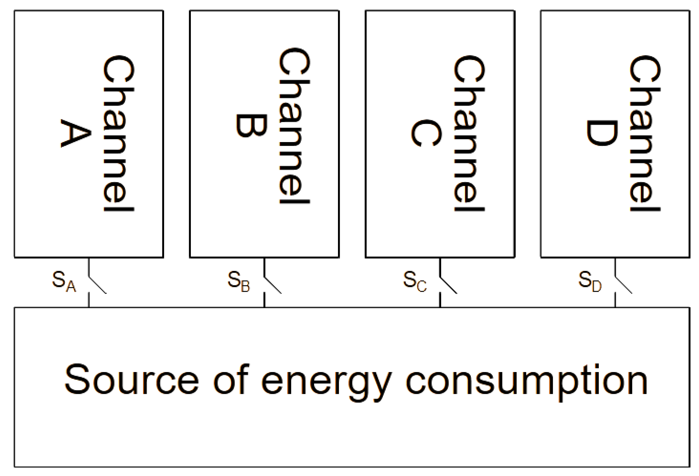
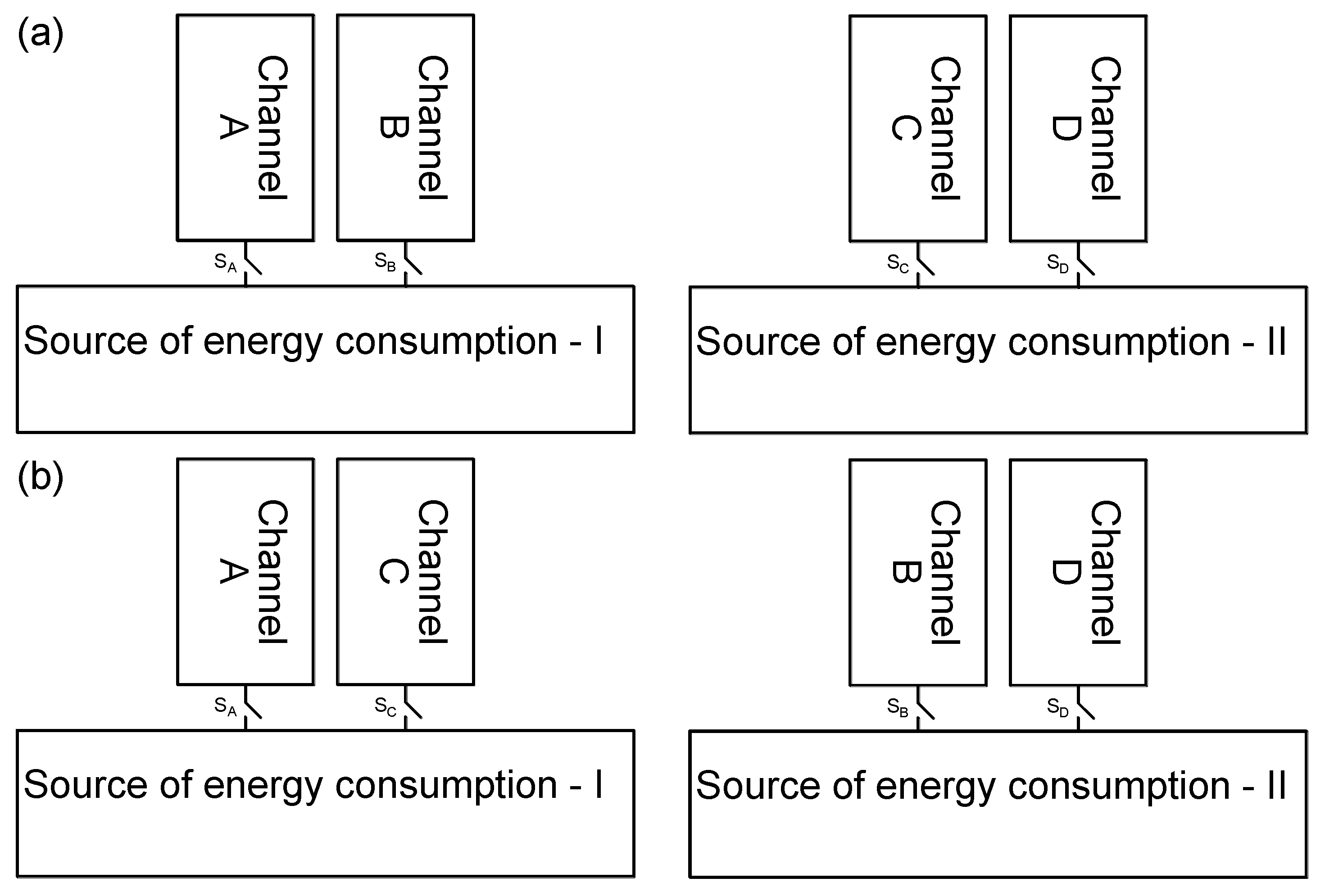
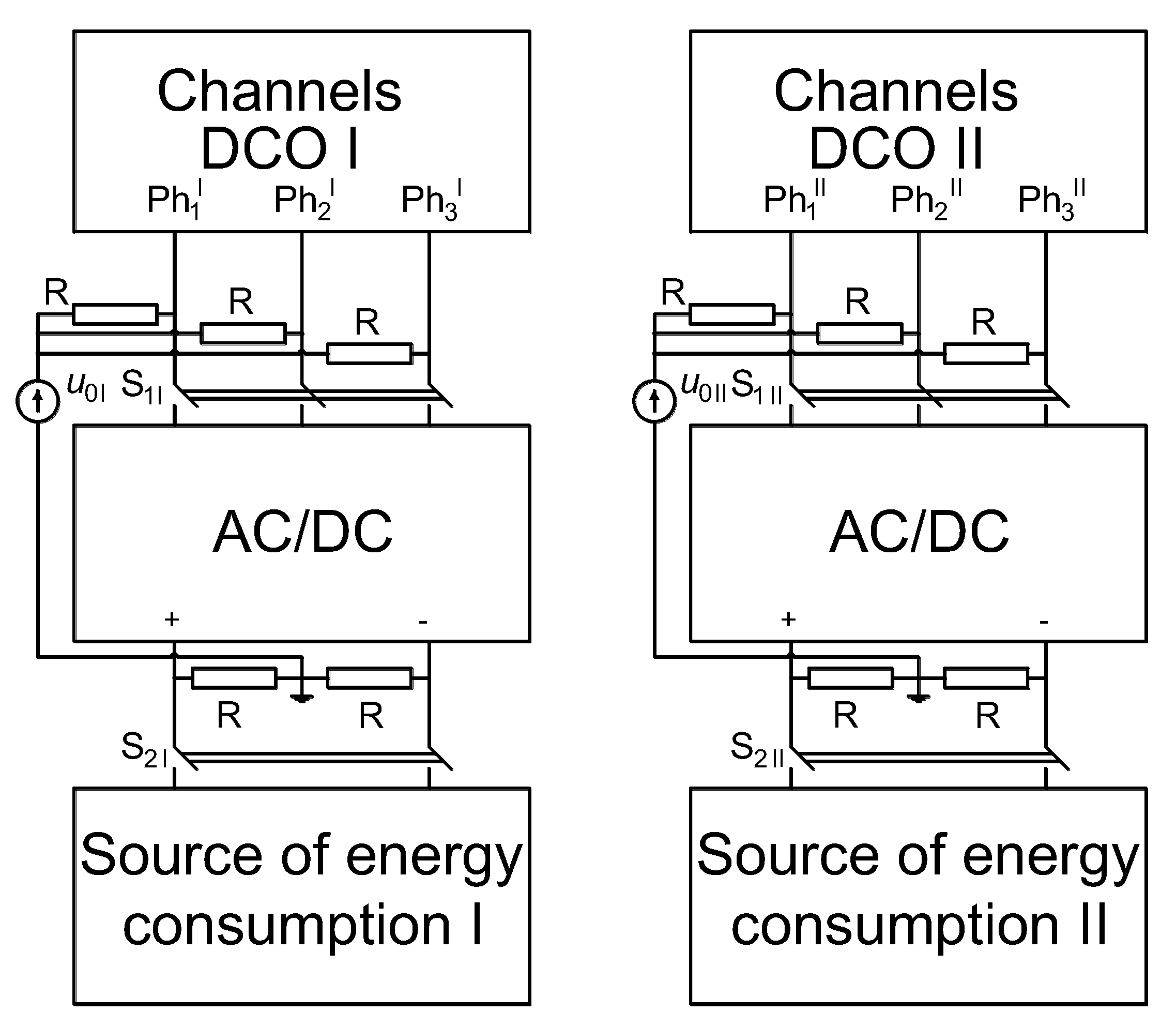
This article proposes the use of the MCPMSG for safety critical applications. In comparison to classical solutions, the use of the MCPMSG allows us to obtain an improvement in the redundancy of the power generation system. The MCPMSG can work with one energy consumption system. In this case, the two channels are treated as redundant. The other option is to work with two independent energy-receiving sources. In both cases, the configuration of the channels is important since it affects the generator operation. The analysis of the MCPMSG properties in various channel configurations is possible due to the mathematical model developed by the authors. Regardless of the type of configuration of individual generator channels, their condition should be monitored in terms of correct operation. Conclusions were formulated on the basis of the tests that were carried out.
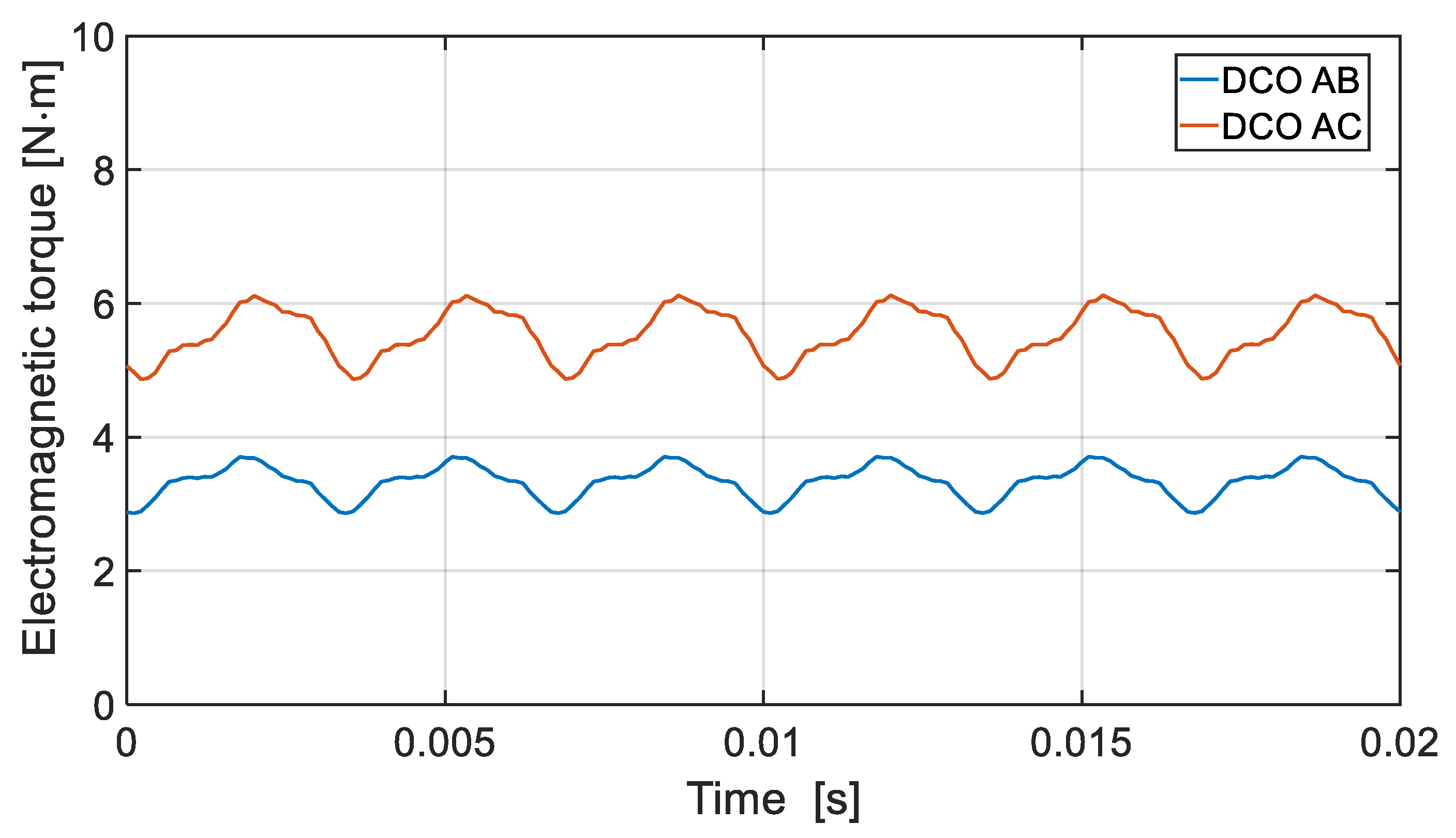
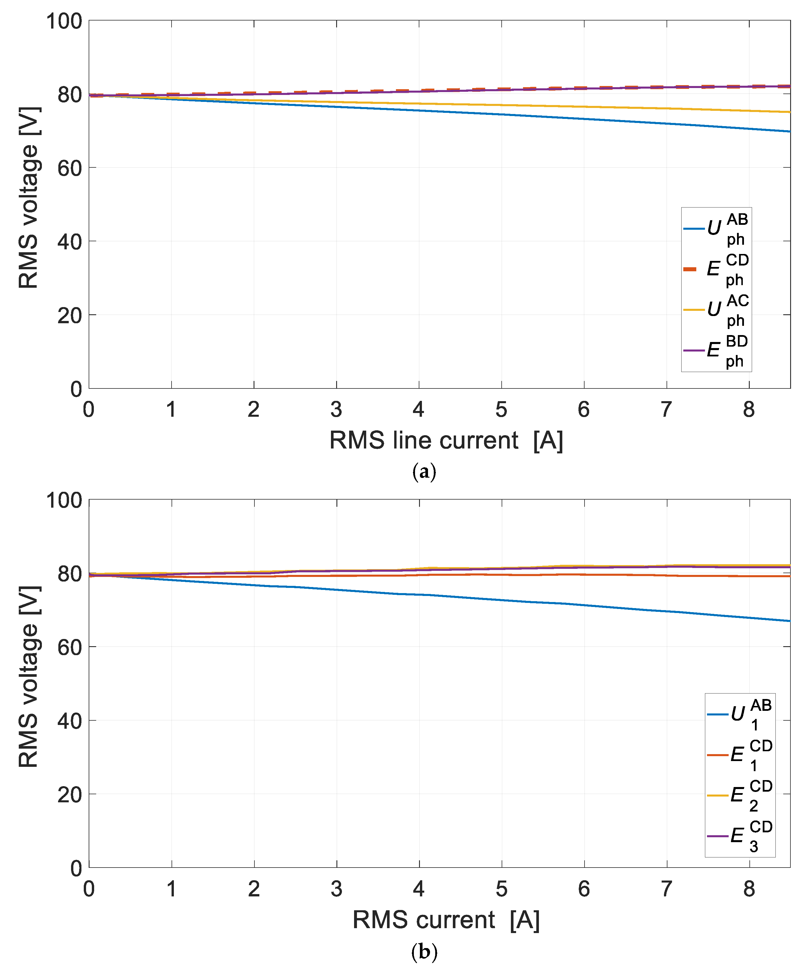
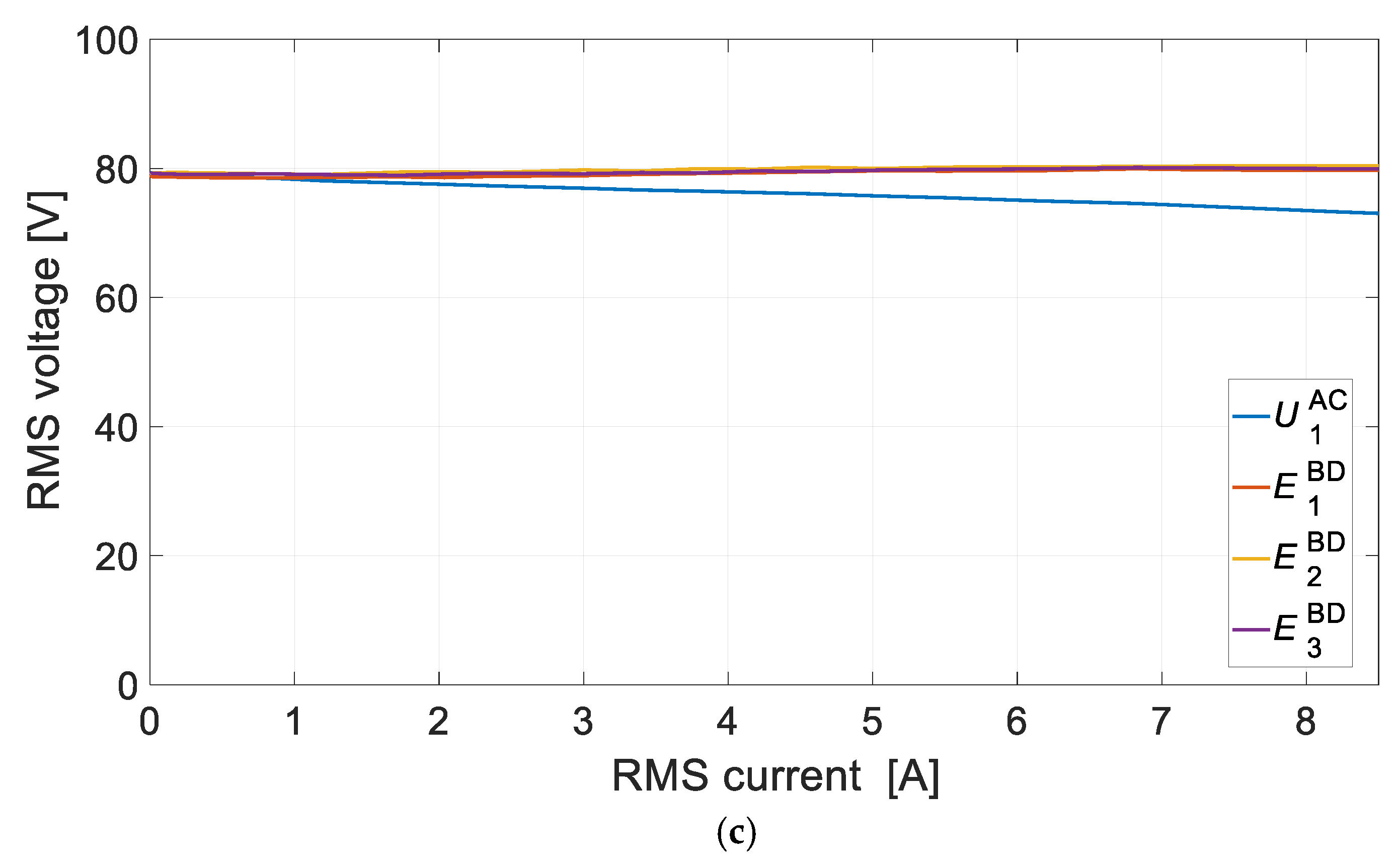
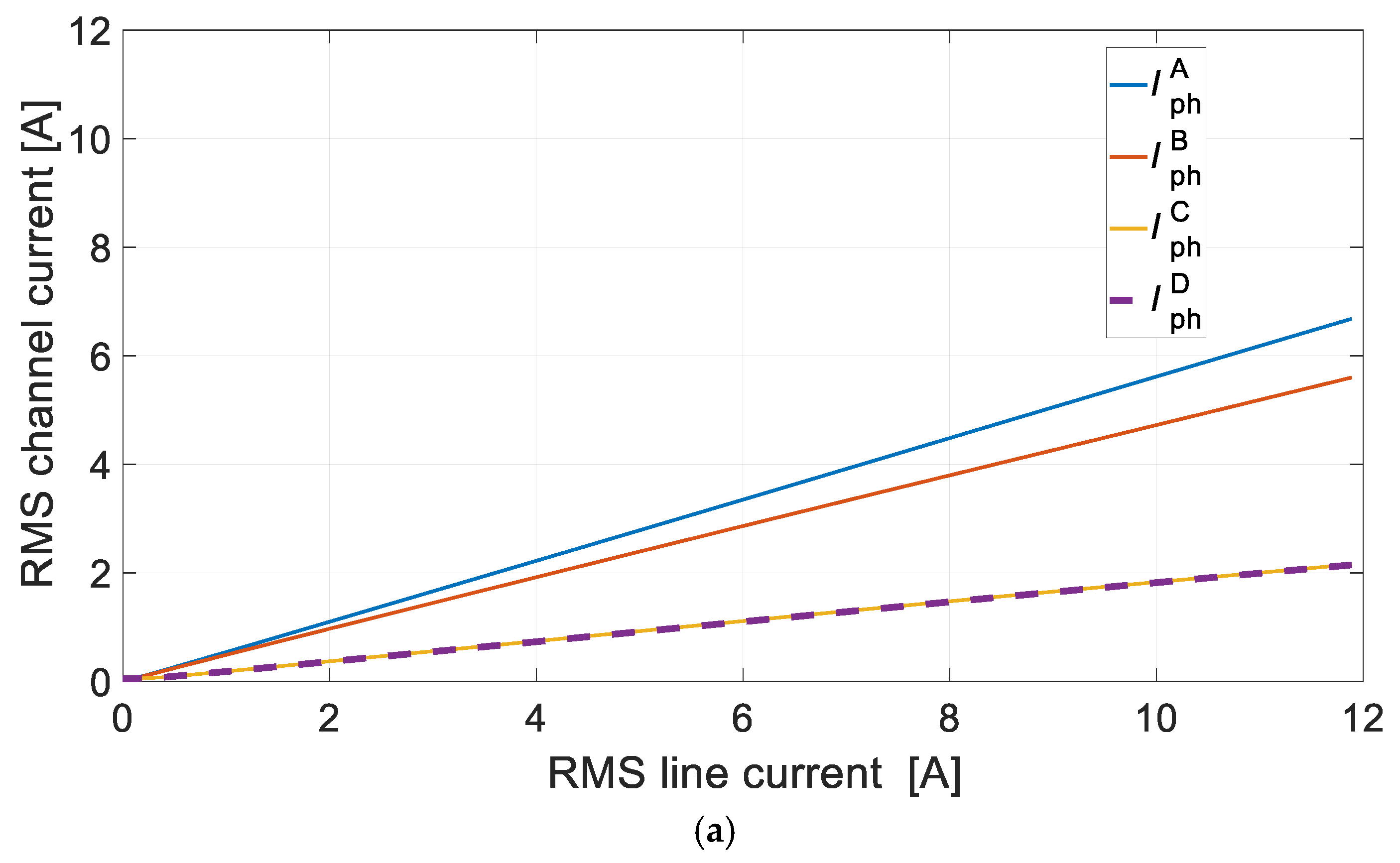
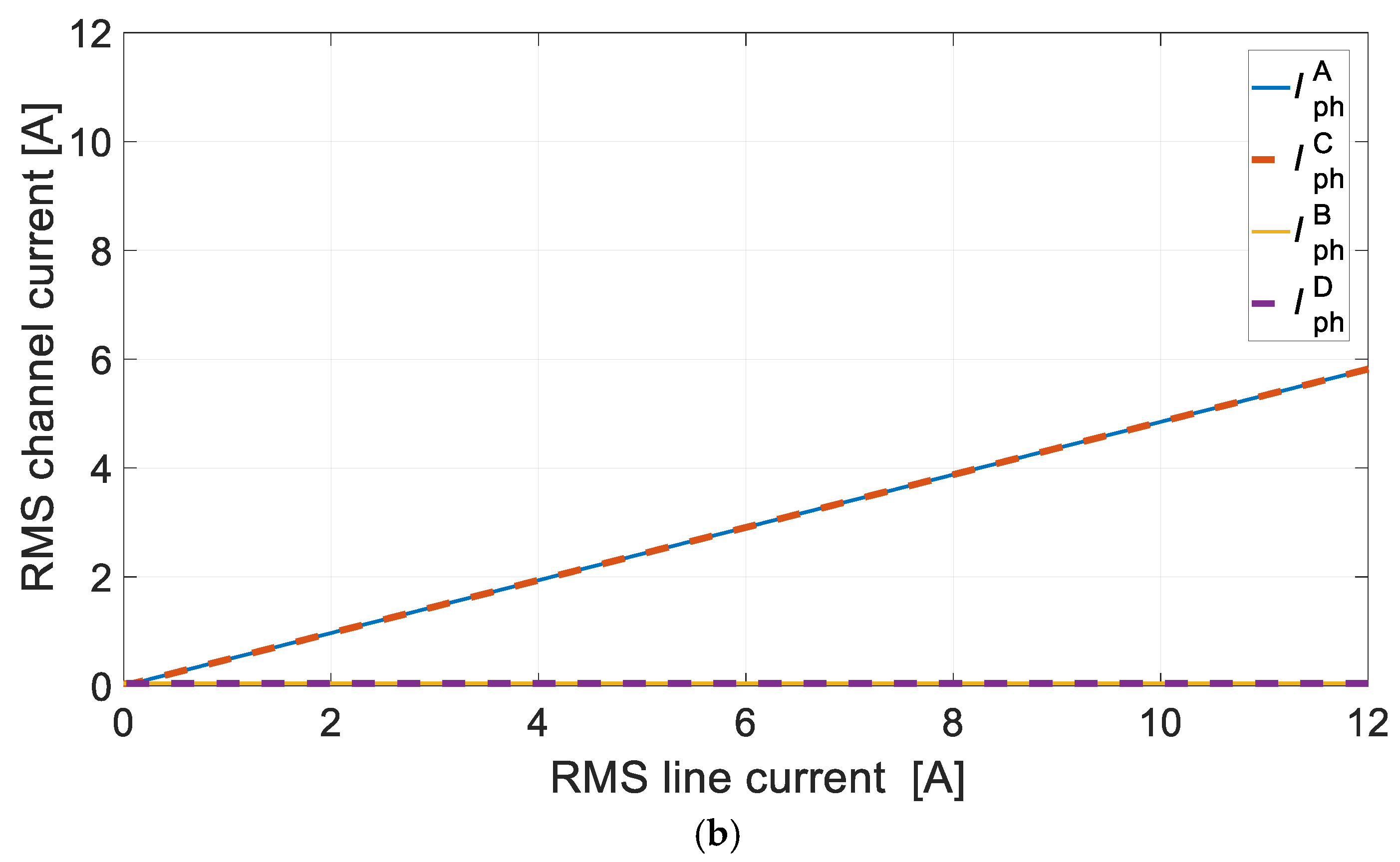
For the DCO it is preferred to use the configuration of the channels that are not magnetically coupled. This solution provides higher efficiency of energy conversion and balanced magnetic tension. In the DCO with magnetically coupled channels, in solitary operation or with various loads, the efficiency deteriorates due to the appearance of equalizing currents.
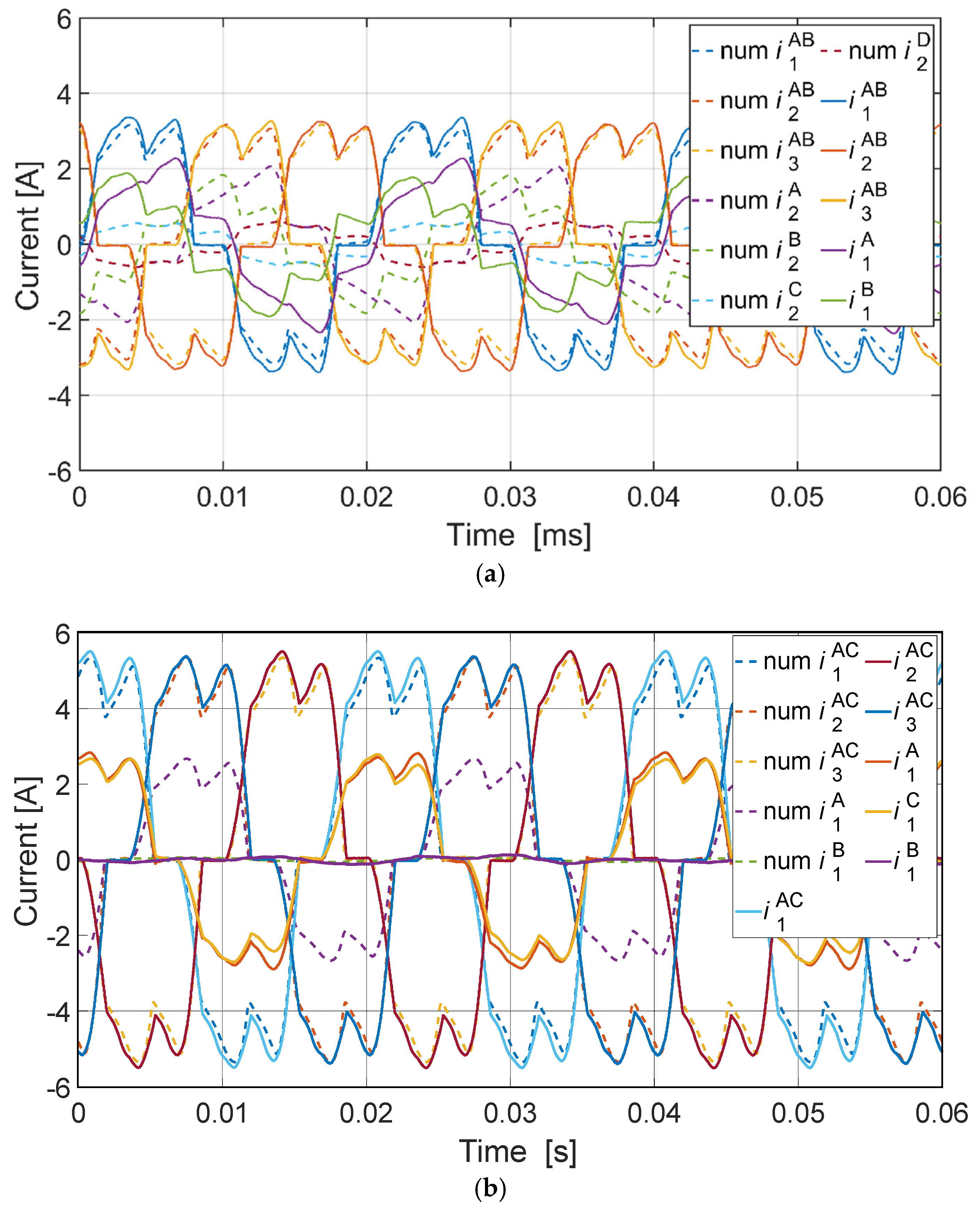
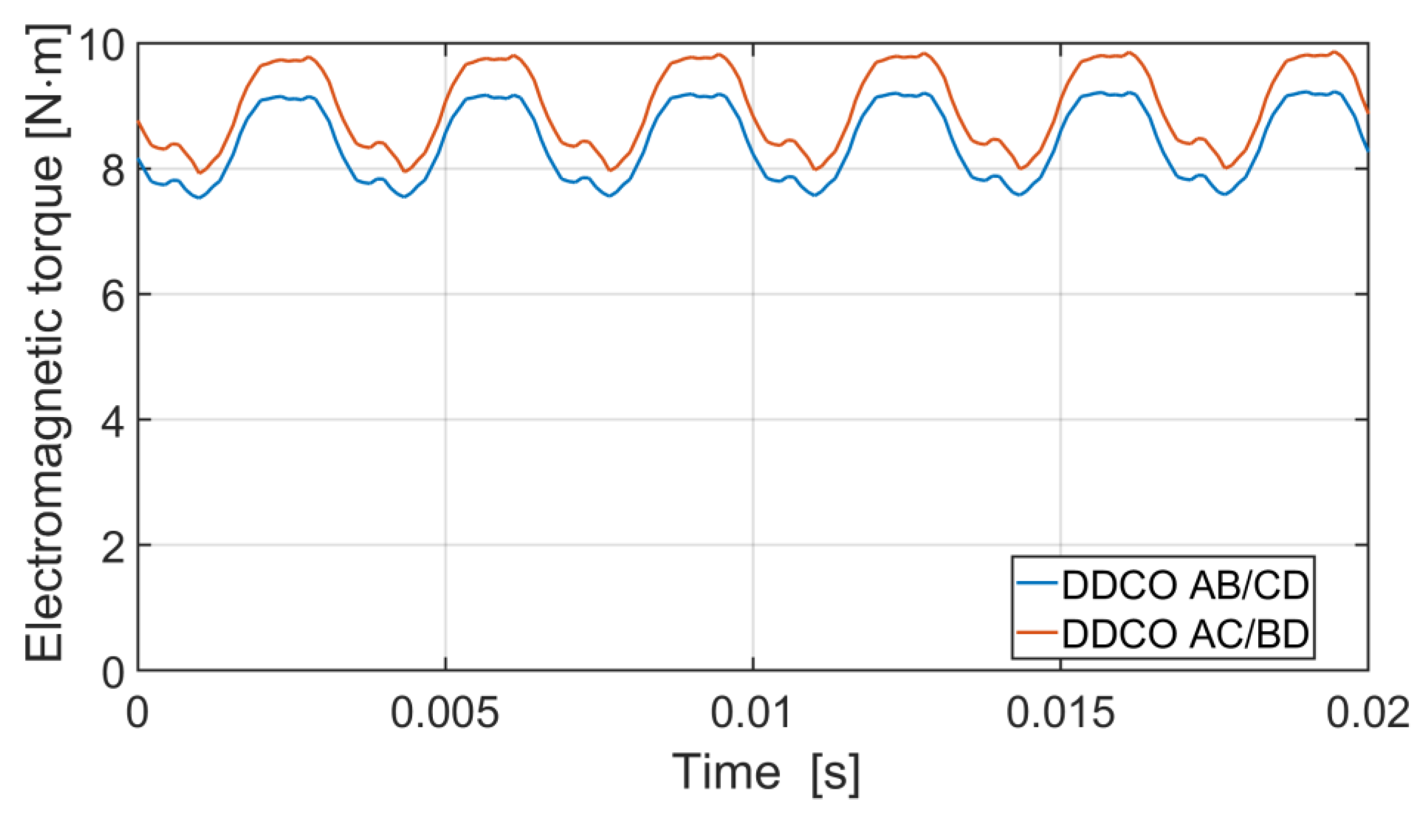
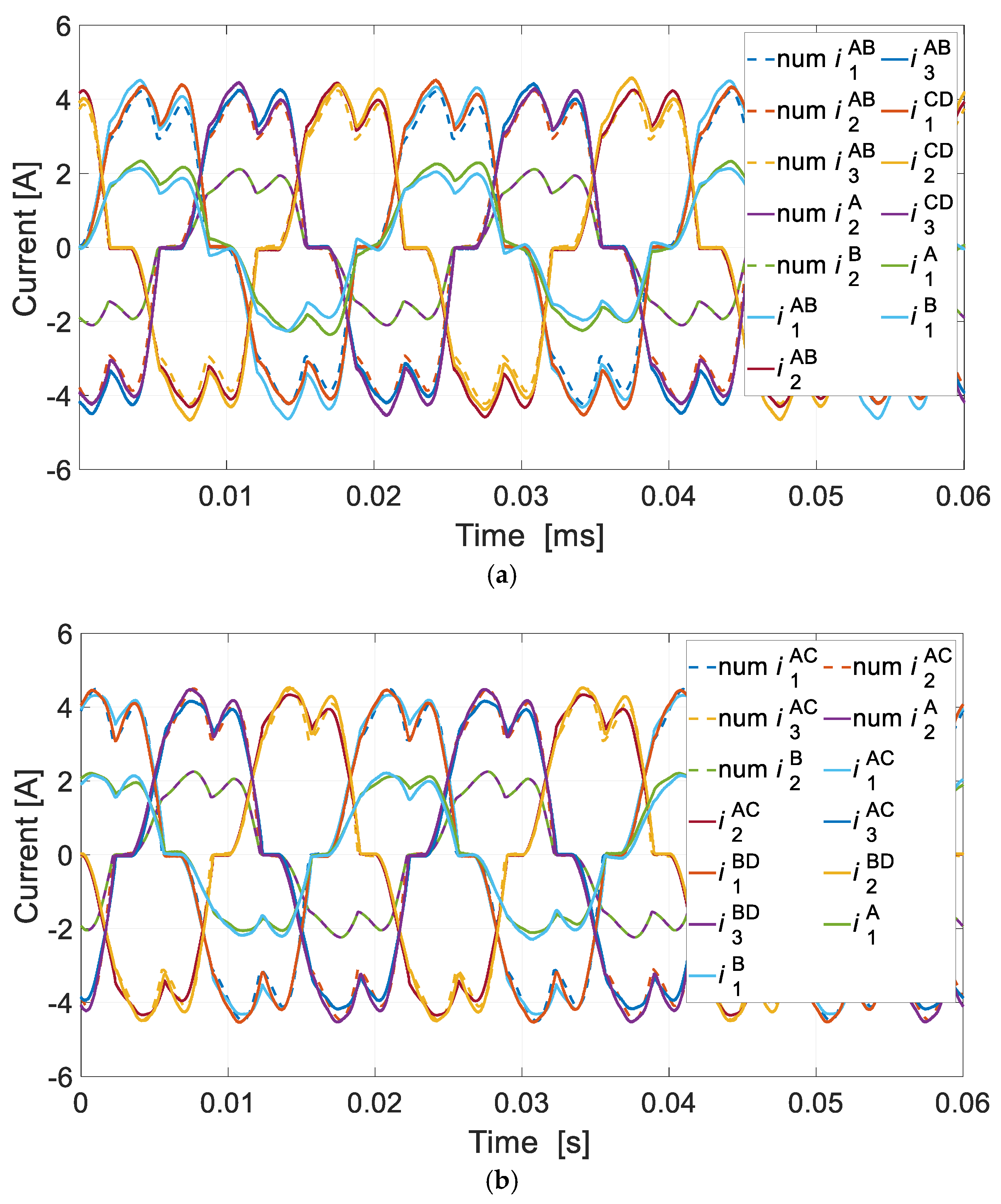
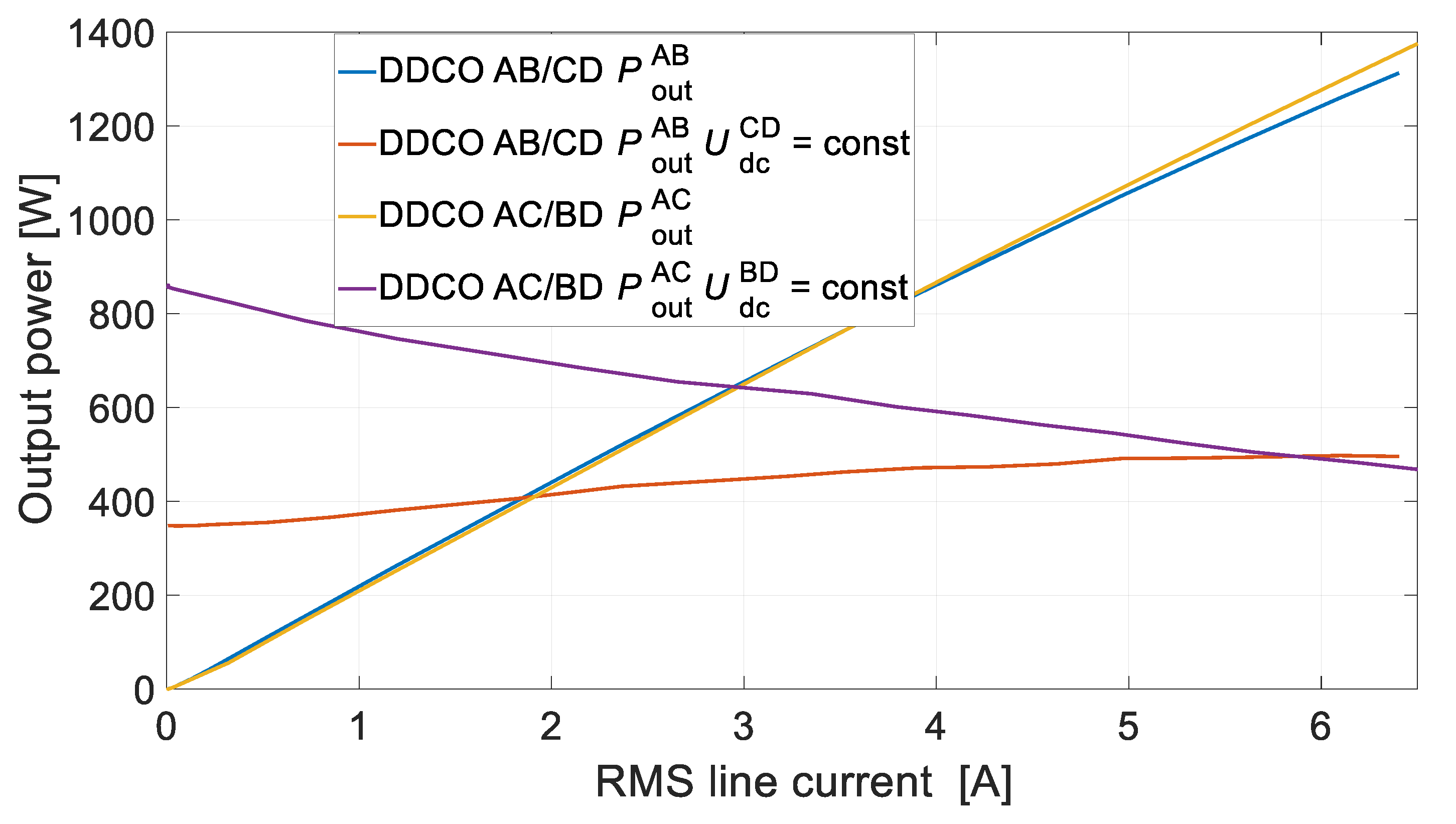
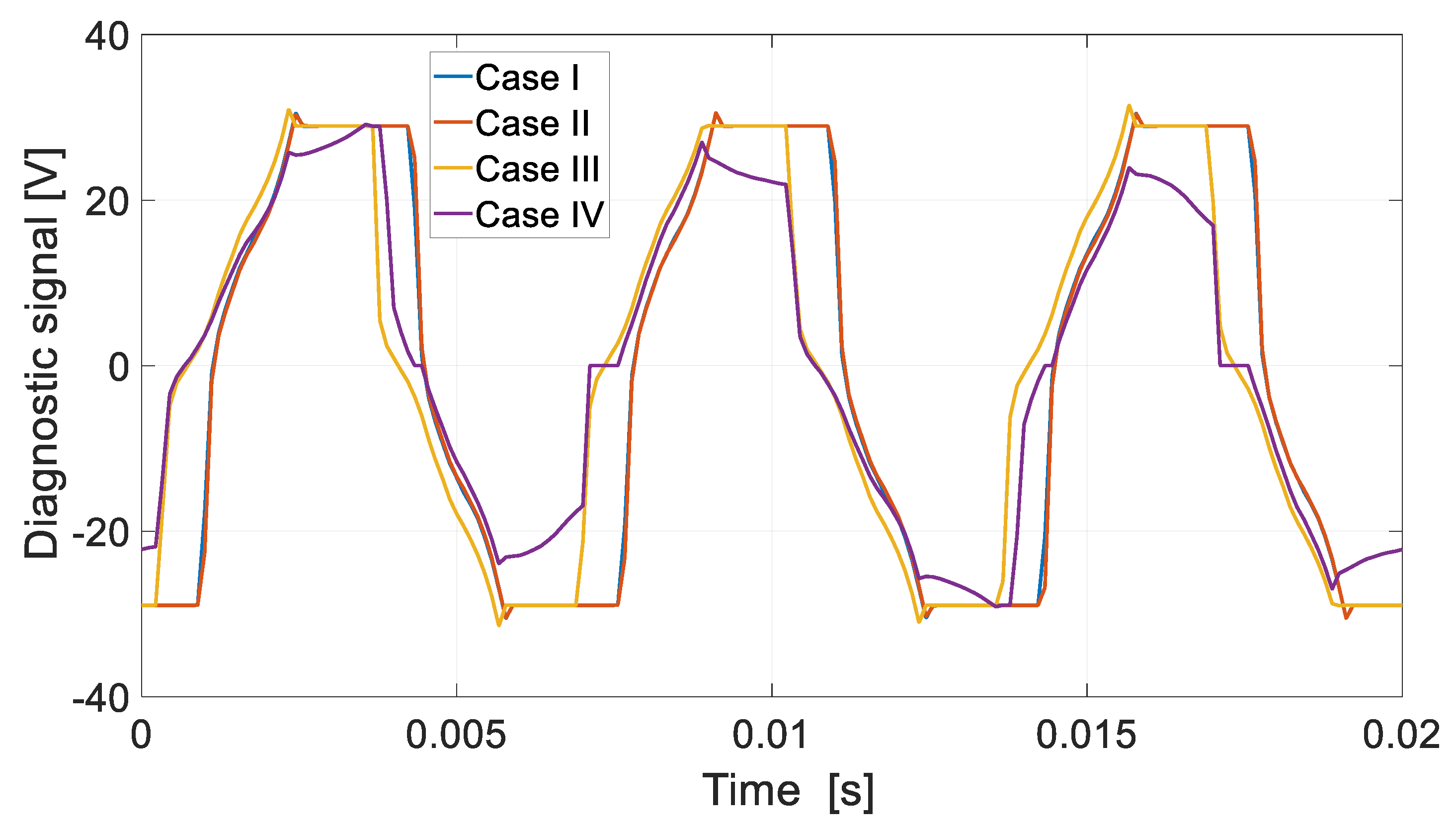
Numerical and laboratory tests have shown that there is more interaction between the DCO AC and the DCO BD channels in the DDCO mode. The change of the DCO AC load affected the operation of the DCO BD. This problem can be reduced by reducing the pitch of the distributed winding or by using a typical concentrated winding. The proposed method of diagnosing the operating state of the channels is based on harmonic analysis of the voltage signal. The appearance of the diagnostic harmonic component in the voltage signal indicates deviations from symmetric operation. The advantage of this approach is the ability to monitor channels in a non-current state. The proposed diagnostic method can also be used under practical conditions to assess machine quality. Even small differences in the values of induced voltages, phase resistances, etc., have an impact on the increase in the diagnostic frequency f1 of the diagnostic signal. The effects of damage to one of the channels are noticeable in the remaining efficient channels. This shows the high sensitivity of the proposed diagnostic method.
The validity of the proposed MCPMSG is verified by the experimental results.
The prototype, the extended mathematical model, and the proposed diagnostic method will allow for further testing of the MCPMSG, e.g., analysis of emergency states such as short circuits (e.g., one turn) in the windings of the band of a given channel.

Author Contributions

Conceptualization, M.K. and E.S.; methodology, M.K. and J.P.; software, M.K.; formal analysis, M.K. and J.P.; investigation, M.K. and E.S.; resources, M.K. and E.S.; data curation, M.K., writing—original draft preparation, M.K. and E.S.; writing—review and editing J.P.; supervision, M.K. and J.P.; project administration, M.K.; funding acquisition, M.K. All authors have read and agreed to the published version of the manuscript.

Funding

This research is financed in part by the statutory funds (UPB) of the Department of Electrodynamics and Electrical Machine Systems, Rzeszow University of Technology, and in part by the Minister of Education and Science of the Republic of Poland within the ‘Regional Initiative of Excellence’ program for the years 2019–2023. Project number 027/RID/2018/19, amount granted: 11,999,900 PLN.

Conflicts of Interest

The authors declare no conflict of interest.

References

  1. Cao, W.; Mecrow, B.C.; Atkinson, G.J.; Bennett, J.W.; Atkinson, D.J. Overview of Electric Motor Technologies Used for More Electric Aircraft (MEA). IEEE Trans. Ind. Electron. 2011, 59, 3523–3531. [Google Scholar] [CrossRef]
  2. Madonna, V.; Giangrange, P.; Galea, M. Electrical Power Generation in Aircraft: Review, Challenges, and Opportunities. IEEE Trans. Transp. Electrif. 2018, 4, 646–659. [Google Scholar] [CrossRef]
  3. Li, J.; Zhang, Z.; Lu, J.; Liu, Y.; Chen, Z. Design and Characterization of a Single-Phase Main Exciter for Aircraft Wound-Rotor Synchronous Starter-Generator. IEEE Trans. Magn. 2018, 54, 8206805. [Google Scholar] [CrossRef]
  4. Wang, Z.; Liu, B.; Guan, L.; Zhang, Y.; Cheng, M.; Zhang, B.; Xu, L. A Dual-Channel Magnetically Integrated EV Chargers Based on Double-Stator-Winding Permanent-Magnet Synchronous Machines. IEEE Trans. Ind. Appl. 2018, 55, 1941–1953. [Google Scholar] [CrossRef]
  5. Bogusz, P.; Korkosz, M.; Prokop, J. A study of dual-channel brushless DC motor with permanent magnets. In Proceedings of the Selected Issues of Electrical Engineering and Electronics (WZEE), Rzeszow, Poland, 4–8 May 2016. [Google Scholar] [CrossRef]
  6. Park, H.; Choi, J.; Jeong, K.; Cho, S. Comparative Analysis of Surface-mounted and Interior Permanent Magnet Synchronous Motor for Compressor of Air-conditioning System in Electric Vehicles. In Proceedings of the 2015 ICPE-ECCE Asia, Seoul, Republic of Korea, 1–5 June 2015. [Google Scholar] [CrossRef]
  7. Tarnapowicz, D. Permanent magnet synchronous generators in a ship’s shaft generator systems. Sci. J. Marit. Univ. Szczec. 2020, 61, 17–22. [Google Scholar] [CrossRef]
  8. Kumar, R.R.; Chetri, C.; Devi, P.; Bose, S. Design and Analysis of Dual Stator Non-Magnetic Rotor Six-Phase Permanent Magnet Synchronous Generator for Marine Power Application. In Proceedings of the 2020 IEEE GUCON, Greater Noida, India, 2–4 October 2020. [Google Scholar] [CrossRef]
  9. Trilla, L.; Pegueroles, J.; Urresty, J.; Muñiz, C.; Gomin-Bellemunt, O. Generator Short-Circuit Torque Compensation in Multichannel Wind Turbines. IEEE Trans. Ind. Electron. 2017, 64, 8790–8798. [Google Scholar] [CrossRef]
  10. Lang, X.; Yang, T.; Enalou, H.B.; Li, C.; Bozhko, S.; Wheeler, P. A Dual-Channel-Enhanced Power Generation Architecture with Back-to-Back Converter for MEA Application. IEEE Trans. Ind. Appl. 2020, 56, 3006–3019. [Google Scholar] [CrossRef]
  11. Dranca, M.A.; Chirca, M.; Breban, S.; Fodorean, D. Comparative Design Analysis of Two Modular Permanent Magnet Synchronous Generators. In Proceedings of the 2021 ISEEE, Galati, Romania, 28–30 October 2021. [Google Scholar] [CrossRef]
  12. Delavari, H.; Veisi, A. Robust Control of a Permanent Magnet Synchronous Generators based Wind Energy Conversion. In Proceedings of the 2021 ICCIA, Tabriz, Iran, 23–24 February 2021. [Google Scholar] [CrossRef]
  13. Setlak, L.; Kowalik, R. Model and Simulation of Permanent Magnets Synchronous Machine (PMSM) of the Electric Power Supply System (EPS), in Accordance with the Concept of a More Electric Aircraft (MEA). ITM Web Conf. 2018, 16, 03004. [Google Scholar] [CrossRef]
  14. Gurleyen, H. Dual-Channel Variable Flux Reluctance Generator Design for More Electric Aircraft. In Proceedings of the IEEE GPECOM2021, Antalya, Turkey, 5–8 October 2021. [Google Scholar] [CrossRef]
  15. Bogusz, P.; Korkosz, M.; Pakla, B.; Prokop, J. Comparative study of the performance of brushless DC motor with permanent magnets under classic and dual-channel operation. In Proceedings of the International Symposium on Elect. Machines (SME), Andrychow, Poland, 10–13 June 2018. [Google Scholar] [CrossRef]
  16. Ding, W. Comparative Study on Dual-Channel Switched Reluctance Generator Performances Under Single- and Dual-Channel Operation Modes. IEEE Trans. Energy Convers. 2012, 27, 680–688. [Google Scholar] [CrossRef]
  17. Ding, W.; Liang, D.; Sui, H. Dynamic Modeling and Performance Prediction for Dual-Channel Switched Reluctance Machine Considering Mutual Coupling. IEEE Trans. Magn. 2010, 46, 3652–3663. [Google Scholar] [CrossRef]
  18. Van der Geest, M.; Polinder, H.; Ferreira, J.A.; Zeilstra, D. Design and Testing of a High-Speed Aerospace Permanent Magnet Starter/Generator. In Proceedings of the 2015 ESARS, Aachen, Germany, 3–5 March 2015. [Google Scholar] [CrossRef]
  19. He, C.; Wu, T. Analysis and Design of Surface Permanent Magnet Synchronous Motor and Generator. CES Trans. Electr. Mach. Syst. 2019, 3, 94–100. [Google Scholar] [CrossRef]
  20. Wang, Y.; Wang, H.; Liu, W.; Wang, Q. Modeling and Analysis of a New Voltage Regulation Method for Surface-Mounted Permanent Magnet Synchronous Generator. In Proceedings of the 2018 IEEE PEMC, Budapest, Hungary, 26–30 August 2018. [Google Scholar] [CrossRef]
  21. Riera-Guasp, M.; Antonino-Daviu, J.A.; Capolino, G. Advances in Electrical Machine, Power Electronic, and Drive Condition Monitoring and Fault Detection: State of the Art. IEEE Trans. Ind. Electron. 2014, 62, 1746–1759. [Google Scholar] [CrossRef]
  22. Abramov, I.V.; Abramov, A.I.; Nikitin, Y.R.; Sosnovich, E.; Božek, P.; Stollmann, V. Diagnostics of Electrical Drives. In Proceedings of the 2015 EDPE, Tatranska Lomnica, Slovakia, 21–23 September 2015. [Google Scholar] [CrossRef]
  23. Gandhi, A.; Corrigan, T.; Parsa, L. Recent Advances in Modeling and Online Detection of Stator Interturn Faults in Electrical Motors. IEEE Trans. Ind. Electron. 2010, 58, 1564–1575. [Google Scholar] [CrossRef]
  24. Korkosz, M.; Prokop, J.; Pakla, B.; Bogusz, P. Frequency analysis in fault detection of dual-channel BLDC motors with combined star–delta winding. IET Electr. Power Appl. 2021, 15, 824–836. [Google Scholar] [CrossRef]
  25. Strangas, E.G.; Clerc, G.; Razik, H.; Soualhi, A. Fault Diagnosis, Prognosis, and Reliability for Electrical Machines and Drives; Wiley: Hoboken, NJ, USA, 2022; ISBN 9781119722755. [Google Scholar]
  26. Ansys Electronics Desktop 2023 R2; Ansys Inc.: Canonsburg, PA, USA, 2023.
  27. Sztajmec, E.; Korkosz, M. A study of multichannel brushless generator with permanent magnets. In Proceedings of the Conference Selected Issues in Power Engineering, Electrical Engineering and Industry 4.0, Rzeszów, Poland, 30 November 2022. [Google Scholar]
Figure 1. Multichannel MCPMSG: (a) cross-section, (b) prototype.
Energies 16 07816 g001
Figure 2. Diagram of the connection of windings of conventional channel A.
Energies 16 07816 g002
Figure 3. Phase EMF waveforms of the MCPMSG.
Energies 16 07816 g003
Figure 4. Analyzed configurations of the channels of the generator operating with one source of energy consumption.
Energies 16 07816 g004
Figure 5. Analyzed configurations of the generator channels operating with two independent energy-receiving sources.
Energies 16 07816 g005
Figure 6. Test stand.
Energies 16 07816 g006
Figure 7. Self- and mutual inductance for (a) SCO A, (b) DCO AB, and DCO AC.
Energies 16 07816 g007
Figure 8. Electromagnetic torque for DCO AB and DCO AC for one source of energy consumption.
Energies 16 07816 g008
Figure 9. Current waveforms for (a) DCO AB and (b) DCO AC.
Energies 16 07816 g009
Figure 10. External characteristics for (a) numerical test, (b) laboratory test for DCO AB, and (c) laboratory test for DCO AC.
Energies 16 07816 g010aEnergies 16 07816 g010b
Figure 11. RMS channel current vs. RMS line current for (a) DCO AB and (b) DCO AC.
Energies 16 07816 g011aEnergies 16 07816 g011b
Figure 12. Electromagnetic torque for the DDCO AB/CD and the DDCO AC/BD for two independent sources of energy consumption.
Energies 16 07816 g012
Figure 13. Current waveforms for (a) DDCO AB/CD and (b) DDCO AC/BD for two independent sources of energy consumption.
Energies 16 07816 g013
Figure 14. Output power vs. RMS value of current of the DDCO AB/CD at UdcCD = const and DDCO AC/BD at UdcBD = const.
Energies 16 07816 g014
Figure 15. Proposition for the location of the diagnostic voltage signal by using the MCPMSG.
Energies 16 07816 g015
Figure 16. Diagnostic voltage signal u0I of DCO—numerical calculations.
Energies 16 07816 g016
Figure 17. Diagnostic voltage signal u0I of DCO—laboratory test.
Energies 16 07816 g017
Figure 18. FFT of the diagnostic voltage signal u0I—numerical calculations.
Energies 16 07816 g018
Figure 19. FFT of diagnostic voltage signal u0I—laboratory test.
Energies 16 07816 g019
Table 1. Selected parameters of the analyzed MCPMSG.
ParameterValue
Number of phases/channels3/4
Number of slots/rotor poles36/4
Stator/rotor diameter140 mm/81 mm
Active length/air-gap140 mm/0.5 mm
Continuous output power for dual-channel operation/nominal speed1500 W/1500 rpm
Nominal output phase voltage73 Vrms
Nominal phase current per channel3.8 Arms
Winding layers2
Winding configurationY
Number of turns per channel phase84
Phase resistance per channel1.8 Ω
Number of independent coil turns in phase 1
of channel A
Coil 1 (1 + 27), coil 2 (3 + 25),
coil 3 (28) (Figure 2)
Permanent magnetN48SH
Table 2. Analyzed operating states of channel A.
Case/SwitchS1S2S3S4S5S6S7S8S9S10
Case Ionoffonoffonoffonoffonoff
Case IIonoffoffononoffonoffonoff
Case IIIonoffonoffonoffoffononoff
Case IVonoffonoffonoffonoffoffon
Table 3. RMS phase EMF of the MCPMSG—laboratory test.
Phase/ChannelChannel AChannel BChannel CChannel D
Phase 182.476 V81.886 V81.963 V81.808 V
Phase 280.987 V81.429 V80.996 V80.622 V
Phase 381.262 V81.102 V81.506 V81.429 V
Table 4. RMS values of phase EMF for dual-channel operation.
Case/BEMFE1E2E3
Case IDCO AB81.40 V81.40 V81.40 V
DCO AC81.44 V81.44 V81.44 V
Case IIDCO AB80.91 V81.43 V81.43 V
DCO AC80.96 V81.44 V81.43 V
Case IIIDCO AB79.96 V81.53 V81.37 V
DCO AC79.86 V81.43 V81.43 V
Case IVDCO AB64.58 V81.84 V81.31 V
DCO AC64.56 V81.52 V81.52 V
Table 5. The MCPMSG with one source of energy consumption.
ModeChannel
QCOABCD
TCOABC|ABD|ACD|BCD
DCOAB *|AC *|AD|BC|BD|CD
SCOA|B|C|D
Table 6. The MCPMSG with two sources of energy consumption.
ModeChannel
TCO + SCOABC + D|ABD + C|ACD + B|BCD + A
Double DCO (DDCO)AB + CD *|AC + BD *|AD + BC
Table 7. Amplitudes of critical diagnostic frequencies in the DCO mode.
Case/Harmonicf1 [mV]f3 [V]f1/f3 [%]
Case Inum7.732.830.023
test6030.780.194
Case IInum9032.670.276
test26029.310.887
Case IIInum27932.310.865
test38028.951.312
Case IVnum344724.2514.21
test430626.7916.08
Table 8. The DDCO mode critical diagnostic frequency amplitudes (Case I).
Case/Harmonicf1 [mV]f3 [V]f1/f3 [%]
CON IDCO I0.7833.40.023
DCO II0.7632.840.023
CON IIDCO I2.3433.870.069
DCO II2.2333.190.067
CON IIIDCO I3.3435.170.094
DCO II3.3435.170.094
CON IVDCO I0.9434.150.027
DCO II0.9735.820.027
Table 9. Critical diagnostic frequency amplitudes in the DDCO mode (CON III).
Case/Harmonicf1 [mV]f3 [V]f1/f3 [%]
CON I—Case IDCO I3.3435.170.094
DCO II3.3435.170.094
CON II—Case IIDCO I63.835.090.182
DCO II56.935.110.162
CON III—Case IIIDCO I202.834.950.58
DCO II117.435.10.335
CON IV—Case IVDCO I533627.7814.54
DCO II110932.453.441
Table 10. Amplitudes of critical diagnostic frequencies of the DDCO mode (CON III)—laboratory test.
Case/Harmonicf1 [mV]f3 [V]f1/f3 [%]
CON I—Case IDCO I7030.650.223
DCO II7231.160.231
CON II—Case IIDCO I296300.987
DCO II15730.90.508
CON III—Case IIIDCO I42731.91.33
DCO II27332.20.848
CON IV—Case IVDCO I28702611.038
DCO II66827.62.42
Disclaimer/Publisher’s Note: The statements, opinions and data contained in all publications are solely those of the individual author(s) and contributor(s) and not of MDPI and/or the editor(s). MDPI and/or the editor(s) disclaim responsibility for any injury to people or property resulting from any ideas, methods, instructions or products referred to in the content.

