Abstract
Modern gas turbines have evolved by increasing the turbine inlet temperature (TIT) to improve performance. This development has led to a demand for cooling techniques. Among these, the film cooling, which involves injecting compressed air through holes on the turbine surface, is a prominent cooling technique used to protect the turbine surface. In this study, a comparative analysis is conducted between the conventional fan-shaped film cooling hole, primarily used in film cooling techniques, and modified shapes achieved by altering the geometry of the film cooling hole based on a fan-shaped hole to assess and compare the cooling performance on a flat plate surface. The adiabatic film cooling effectiveness was measured for three film cooling holes, the Baseline of a 7-7-7 fan-shaped film cooling hole, namely, Staircase, which had a double-step at the hole exit, and Compound Expansion, which had an additional expanded flow path at the hole leading edge. The used measurement technique was the pressure-sensitive paint (PSP) technique, using nitrogen gas as the foreign gas, and experiments were conducted at a density ratio of 1.0 and blowing ratios ranging from 0.5 to 2.0. The results reveal that the modified holes featured wider lateral expansion at the hole exits, resulting in a broader distribution of the cooling effectiveness in the lateral direction compared to the Baseline. The Staircase shows a better performance, although an overall cooling effectiveness trend similar to that of the Baseline. Furthermore, the Compound Expansion demonstrates an enhancement in the cooling performance with an increased blowing ratio, notably achieving nearly double the cooling effectiveness compared to that of the Baseline at a blowing ratio of 2.0.
1. Introduction
Modern gas turbines have advanced by increasing the turbine inlet temperature (TIT). However, a high TIT leads to significant thermal loads on the turbine. As a result, various turbine cooling techniques have been developed. Film cooling is one of the widely employed methods for turbine cooling, where a coolant is injected through holes on the turbine surface to protect it from the hot gas from the combustor [1,2,3,4].
The film cooling performance is influenced by various factors, including the shape of the cooling hole, injection angle, flow conditions, compound angle, and turbulence intensity of the mainstream flow [5,6,7,8]. Considerable research has been conducted to enhance the performance of film cooling by changing the various shapes of the cooling hole, which includes simple cylindrical holes, fan-shaped holes, and arrowhead-shaped holes [9,10,11,12].
Also, to improve the film cooling performance, several approaches have been investigated, focusing on changes beyond the cooling hole geometry. Research [13,14,15] has been conducted to enhance the film cooling performance by employing a trench structure machined in the cooling hole. This approach shows the lateral dispersion characteristic of the cooling fluid to improve the uniformity of cooling effectiveness and relieve the lift-off phenomena, resulting in an improved film cooling performance. The research by Kim et al. [16] and Benabed et al. [17] aimed to enhance the film cooling performance by considering the Coanda effect. Furthermore, the studies by Zhang et al. [18] and Fox et al. [19] investigated enhancing the cooling performance by constructing external structures around the cooling hole.
As previously mentioned, various attempts to enhance the film cooling performance are underway by modifying the shape of the cooling holes. In this study, modified cooling hole shapes based on the fan-shaped film cooling hole are proposed to enhance the film cooling performance. Measurements of the adiabatic film cooling effectiveness are conducted for the 7-7-7 fan-shaped film cooling hole, the Baseline with a double-step at the hole exit (Staircase), and the Baseline with additional flow path at the hole leading edge (Compound Expansion). Moreover, the characteristics of cooling for these are analyzed. The measurement method was the pressure-sensitive paint (PSP) technique, which utilizes a mass heat transfer similarity. The PSP technique is a commonly employed method for measuring adiabatic film cooling effectiveness in film cooling studies. To employ the PSP technique, an LED emitting light at specific frequencies and a CCD camera for capturing the results were installed in the test rig. The mainstream flow within the test rig was supplied using a wind tunnel, and coolant was provided using a compressor (air) and a high-pressure cylinder tank (nitrogen). The test conditions were a density ratio (DR) condition of 1.0, with the blowing ratio (M) varying from 0.5 to 2.0. An analysis was performed using the measured film cooling effectiveness of each hole to examine the change in cooling performance and the characteristics of the cooling holes.
2. Experimental Setup and Method
2.1. Geometry of the Film Cooling Hole
In this study, a total of three configurations were experimentally tested on a flat plate, including the 7-7-7 fan-shaped film cooling hole studied by Kim et al. [20] and two modified-shaped holes. The fan-shaped film cooling hole has a design in which the exit of the hole is expanded compared to the typical cylindrical hole. This design provides an advantage by reducing the coolant injection velocity compared to conventional cylindrical holes, thus enhancing the cooling performance [4]. However, under high blowing ratios, the coolant still exhibits separation from the surface.
The Baseline selected for this study was the 7-7-7 fan-shaped film cooling hole, featuring exit expansion angles of 7° in both the lateral and streamwise directions. The relevant information is presented in Table 1 and Figure 1.

Table 1.
Geometric parameters for the Baseline [20].
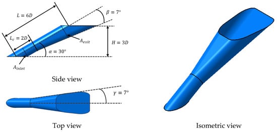
Figure 1.
7-7-7 Fan-shaped film cooling hole configuration (Baseline) [20].
To improve the cooling performance of the previously described fan-shaped film cooling hole, Figure 2 and Figure 3 present schematic representations of the modified hole configurations, namely, Staircase [20] and Compound Expansion [21], respectively. The conventional film cooling holes show that the coolant is concentrated along the hole’s centerline, resulting in the highest cooling effectiveness being at the centerline. Also, when the coolant is injected through the fan-shaped film cooling hole, detachment from the surface occurs due to its high momentum, especially under high blowing ratio conditions. To address these issues, a previous study introduced holes with a dual-step structure at the trailing edge of the hole exit [20]. The purpose of this design is twofold. Firstly, through the step structure, it aims to decrease the momentum of the injected coolant, thereby reducing its separation from the surface. Secondly, it is designed to expand the double-step structure laterally to achieve a more uniform distribution of the coolant rather than a concentration along the centerline. The shape with a step structure used in this study is illustrated in Figure 2.
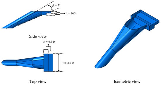
Figure 2.
Baseline with a staircase geometry at the hole exit (Staircase) [20].
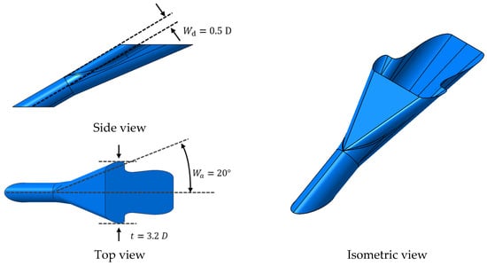
Figure 3.
Baseline with an additional flow passage at the hole leading edge (Compound Expansion) [21].
Under high blowing ratio conditions, the coolant tends to concentrate and accelerate upstream of the inside of the hole. Therefore, the additional expanded passage to disperse this high-momentum coolant was manufactured to enhance the cooling effectiveness under high blowing ratio conditions. In the Compound Expansion, the leading edge of the Baseline is modified with an expanded passage at an angle of 20° in the lateral direction, and with a size half of the hole diameter. Geometric information about the Compound Expansion is presented in Figure 3 [21]. Table 2 summarizes the characteristics of each hole proposed in this study.

Table 2.
Summary of the hole characteristics.
2.2. Experimental Method
The pressure-sensitive paint (PSP) method, as proposed by Zhang et al. [22,23], was used in this study. PSP is commonly used in experiments to measure the adiabatic film cooling effectiveness, making use of its characteristics and similarity in mass heat transfer. The adiabatic film cooling effectiveness can be obtained using the following Equation (1) [24].
In Equation (1), η represents the adiabatic film cooling effectiveness. and are the partial pressure of oxygen when air and foreign gas are injected as the coolant, respectively. is the molecular weight of the foreign gas, and is the molecular weight of the air. The ratio of the molecular weight is , which represents the density ratio of the coolant to mainstream.
To calculate the adiabatic film cooling effectiveness using Equation (1), it is necessary to establish the correlation between the oxygen partial pressure and the luminescence intensity of the PSP. The intensity of the PSP was captured by placing the sample plate in the vacuum chamber to vary the chamber pressure. A LED (LM2X-DM-400, ISSI, Dayton, OH, USA) and a CCD camera (PSP-CCD-M, ISSI, Dayton, OH, USA) were used for the measurements, which were also performed on the flat plate test. A binary FIB PSP in ISSI was utilized in this study, showing negligible temperature effects within the range of 10~40. A calibration curve was created through PSP and the vacuum chamber, which is presented in Figure 4. The calibration curve represents the relationship between the surface oxygen partial pressure ratio and the luminous intensity ratio on the surface. corresponds to luminescence under atmospheric pressure (), while represents the intensity after reduced pressure (P) inside the vacuum chamber. In the calibration curve, it can be observed that, as the surface oxygen partial pressure decreases, the intensity becomes brighter. The sensitivity to pressure for the used PSP is 0.7%, while the sensitivity to temperature is 0.05%. The blowing ratio was determined by measuring the mass flow rate of 0.25%. Based on Natsui et al. [25], the uncertainty of the adiabatic film cooling effectiveness in these experiments was approximately ±4.5% at η = 0.5 and ±11.0% at η = 0.2.
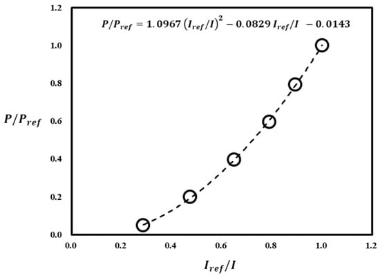
Figure 4.
PSP calibration curve.
2.3. Test Facility
In Figure 5, a schematic diagram of the test facility is presented. The mainstream supply was provided by a subsonic wind tunnel and the velocity of the mainstream was measured using a pitot tube. To apply the PSP method, air and nitrogen gases were supplied through the cooling holes in the test plate. Air was supplied using a 20 hp compressor, while nitrogen was supplied from a high-pressure cylinder tank. The mass flow rate of the coolant gas for the experiment was measured using a Coriolis flow meter installed in the supply line, and the coolant flow was controlled by a valve installed downstream of the mass flow meter. To ensure a uniform coolant injection, wire meshes were installed in the chamber of the hole inlet. K-type thermocouples were installed in both the mainstream and coolant flow paths to measure the temperature of each flow. Figure 6 shows the test plate model used in this experiment. The test plates were manufactured using the SLA (Stereo-Lithography) 3D printing method. For the experiment, a total of five holes were manufactured with a hole-to-hole spacing of 6.0 D for each hole configuration. To reduce errors due to side wall effects within the test rig, this study focused on the central three holes.
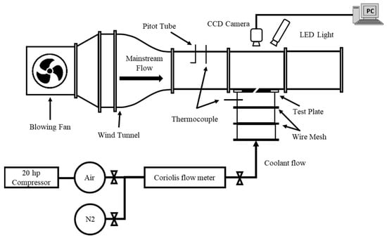
Figure 5.
A schematic diagram of the experimental facility [20].
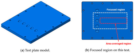
Figure 6.
The test plate model adopted in this test (Baseline) [20].
2.4. Test Conditions
A summary of the test conditions is presented in Table 3. In this test, the mainstream flow was generated through a subsonic wind tunnel, and the velocity of the mainstream flow was Ma = 0.057. Due to using nitrogen as the foreign gas for the PSP method, the density ratio was 1.0. The supply flow rate of coolant flow was adjusted to cover 3 blowing ratios, ranging from 0.5 to 2.0. Hot-wire anemometry was employed to measure the mainstream velocity and turbulence intensity profile at x/D = −12. The measurement results are presented in Figure 7. It shows that the boundary layer thickness was about 3.6 D and the mainstream turbulence intensity was about 1.2%.

Table 3.
Summary of the test conditions [20].
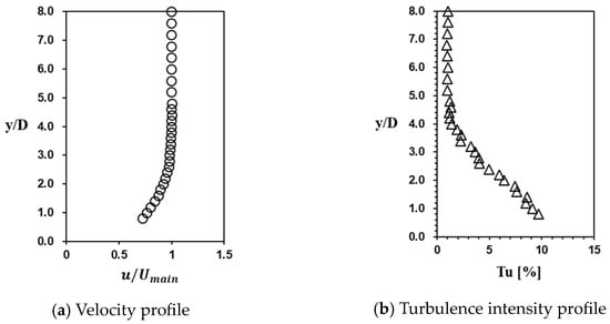
Figure 7.
Velocity and turbulence intensity profile at x/D = −12 [20].
3. Results and Discussion
In this section, the results of the adiabatic film cooling effectiveness measurements for the film cooling holes described earlier are presented. The proposed film cooling holes (Staircase and Compound Expansion) were designed with the intention of improving the cooling performance compared to that of the Baseline. Therefore, the adiabatic film cooling effectiveness distribution for each hole was compared to the blowing ratio, and a comparative analysis of the cooling performance of each hole was conducted.
3.1. Distribution of the Film Cooling Effectiveness
Figure 8, Figure 9 and Figure 10 present the experimental results of the adiabatic film cooling effectiveness for each hole under blowing ratios ranging from 0.5 to 2.0. Figure 8 shows the distribution of the adiabatic film cooling effectiveness at M = 0.5. Although the cooling effectiveness shows variations in the lateral direction depending on the width of the hole exit, it generally demonstrates a similar distribution of cooling effectiveness. The Compound Expansion appears to yield measurements comparable to other hole configurations near z/D = 0, but shows a lower cooling effectiveness downstream. The coolant entering the film cooling hole tends to accelerate towards the upstream of the inside of the hole due to the separation generated at the hole inlet. Consequently, under high blowing ratio conditions, the coolant is injected from the hole exit with a high momentum, leading to a reduced cooling performance as it detaches from the surface. The Compound Expansion configuration aims to mitigate the lift off phenomenon by diffusing the increased coolant momentum generated through internal acceleration within the hole, thereby minimizing the effect. However, at low blowing ratios like M = 0.5, the decreased momentum of the injected coolant can cause an inflow of the mainstream. The inflow of the mainstream, mixing within the hole, and the reduction in the momentum of the injected coolant contributed to the lower film cooling effectiveness downstream in the case of the Compound Expansion, compared to the other configurations.

Figure 8.
Contour plots of the film cooling effectiveness for the various hole configurations at M = 0.5.

Figure 9.
Contour plots of the film cooling effectiveness for the various hole configurations at M = 1.0.

Figure 10.
Contour plots of the film cooling effectiveness for the various hole configurations at M = 2.0.
Figure 9 shows the distribution of the adiabatic film cooling effectiveness at M = 1.0. The trajectory of the cooling effectiveness for all holes spreads downstream compared to the blowing ratio of 0.5, resulting in an improved cooling effectiveness. In the case of the Compound Expansion, the pattern of cooling effectiveness exhibits a distinctive behavior compared to the other hole configurations. The unique cooling pattern exhibited by the Compound Expansion can be attributed to the additional expanded flow passage. The additional expanded flow passage of the Compound Expansion has a significant lateral expansion angle of 20 degrees. Due to this expanded flow passage, the coolant injected from the Compound Expansion at M = 1.0 was estimated to exhibit a flow structure similar to that shown in Figure 11b. This flow structure shows a different distribution of coolant flow compared to that of previous studies. Therefore, it is estimated that the reason for the difference in the distribution pattern of the film cooling effectiveness from the other configurations is attributed to variations in the behavior of the coolant.
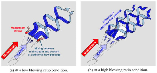
Figure 11.
Schematics of the flow structure around the Compound Expansion hole.
At conditions over M = 1.0, the unique film cooling effectiveness distribution of the Compound Expansion in Figure 9c and Figure 10c can be observed compared to the other configurations, but in the results shown in Figure 8c at M = 0.5 conditions, it shows the effectiveness pattern in the result similar to the result of other configurations. This result is a consequence of the lower injection mass flow rate, which results in the reduced momentum of the injected coolant. As previously mentioned, when the momentum of the coolant is reduced, a phenomenon occurs where the mainstream enters the film cooling holes. The Compound Expansion, owing to the additional expanded flow passage, leads to a relatively lower momentum of the injected coolant, especially when the coolant is not injected enough through the expanded passage, making it prone to the inflow of mainstream flow. The inflow of mainstream causes the mixing between the mainstream and coolant at the additional flow passage, and the coolant to be concentrated toward the centerline of the holes, resulting in a film cooling effectiveness pattern similar to other configurations. The schematic of the flow structure related to the mainstream inflow at the low blowing ratio, such as M = 0.5, is shown in Figure 11a. Considering the flow structure, it can be estimated that the unique characteristics of the Compound Expansion become apparent from a certain blowing ratio condition and above.
The contour plots of the film cooling effectiveness at M = 2.0 are presented in Figure 10. The film cooling effectiveness trajectories for each hole are observed to extend down-stream. All cases show a lower effectiveness near the hole exit due to the coolant lift off effect under the high blowing ratio. The Baseline and the Staircase show a narrower distribution of the film cooling effectiveness in the lateral direction compared to the effectiveness at M = 1.0. However, the Compound Expansion stands out by demonstrating a consistently high film cooling performance even in the downstream region compared to the other configurations. The higher cooling performance of the Compound Expansion compared to other configurations can be attributed to its characteristic of effectively reducing the high momentum of the coolant through the additional passage, thereby reducing the lift off effect. As a result, the Compound Expansion maintains a high cooling effectiveness in the downstream region due to maintaining the injected coolant compared to the other configurations.
In Figure 12, the film cooling effectiveness distribution at x/D = 2 is shown for each configuration at different blowing ratios. As observed in the previous film cooling effectiveness distribution, all configurations exhibit an increase in effectiveness as the blowing ratio increases from 0.5 to 1.0. Furthermore, as confirmed in the cooling effectiveness distribution, the Baseline and the Staircase show a decrease in the cooling effectiveness near the z/D = 0 and a reduction in the lateral effectiveness distribution at M = 2.0. However, the Compound Expansion shows a decrease in the cooling effectiveness at M = 2.0, but the width of the cooling effectiveness distribution remains the same as that at M = 1.0. Through this observation, it can be confirmed that, despite the decrease in the cooling performance due to the lift off effect resulting from the increase in the blowing ratio, the Compound Expansion remains more effective under high blowing ratio conditions, as the lateral width of the film cooling effectiveness distribution does not decrease.

Figure 12.
Lateral distribution of the film cooling effectiveness at x/D = 2.
Figure 13 shows the film cooling effectiveness distribution at x/D = 5 for various blowing ratios. At M = 0.5, in Figure 13a, despite the lateral expansion of the exit area in the modified configurations compared to the Baseline, there is minimal difference in the lateral distribution of the film cooling effectiveness. At low blowing ratio conditions, the reduced momentum of the coolant leads to increased mixing with the mainstream. As the hole outlet is expanded, this effect becomes more pronounced. Thus, it can be inferred that the expanded hole exit area has a limited impact on enhancing the film cooling performance under low blowing ratio conditions. At a blowing ratio of 1.0, the modified configurations show a broader lateral distribution of the film cooling effectiveness compared to the Baseline. With a higher cooling fluid momentum, the mitigated mixing effect aligns better with the design intent of each configuration, resulting in an enhanced film cooling performance. For a blowing ratio of 2.0, the Baseline and the Staircase show negligible differences near z/D = 0. However, the Staircase benefits from its lateral steps, which allow for a wider coverage of the coolant around the hole center. This suggests that the Staircase can be considered superior to the Baseline due to its wider lateral distribution of film cooling effectiveness, even if the near-hole region appears similar or has a higher effectiveness. The Compound Expansion shows a distinct cooling effectiveness near z/D = 0, compared to the other configurations, with a slightly lower film cooling effectiveness. However, it exhibits a wider lateral distribution of film cooling effectiveness. The expanded flow passage contributes to a broader exit area coverage compared to the other configurations, leading to an improved cooling coverage overall. Additionally, the degradation in effectiveness near the centerline is not significantly pronounced, contributing to an overall improved film cooling performance compared to the other holes. This demonstrates the better cooling performance achieved by the Compound Expansion through its expanded exit area geometry, which offers a broader protection and mitigates the cooling effectiveness decrease near the centerline, leading to an enhanced cooling effectiveness.

Figure 13.
Lateral distribution of the film cooling effectiveness at x/D = 5.
3.2. Averaged Film Cooling Effectiveness
The plots of the laterally averaged film cooling effectiveness for each blowing ratio are shown in Figure 14. In Figure 14a, similar levels of cooling performance are observed near the hole exit, but in the case of the Compound Expansion, a decrease in effectiveness is shown downstream. This can be caused by the fact that the injected coolant has a decrease in momentum as it passes through the additional expanded flow passage, resulting in enhanced mixing with the mainstream. In Figure 14b, all the improved holes show a higher cooling performance compared to the Baseline at M = 1.0. Among them, the Com-pound Expansion shows the highest effectiveness at the hole exits, while the improved holes show similar levels of effectiveness downstream. When referencing the distribution of the film cooling effectiveness in Figure 13, although the laterally averaged effectiveness is similar, the distribution of the film cooling effectiveness reveals that the Staircase shows a higher effectiveness at the centerline, while the Compound Expansion provides a wider region of surface protection. In Figure 14c, which corresponds to a blowing ratio of 2.0, the Baseline and the Staircase show a decrease in the cooling performance due to lift off. However, the Compound Expansion shows an overall increase in cooling effectiveness, unlike the other configurations. The Compound Expansion geometry was intended to address the decrease in the cooling performance caused by lift off at a high blowing ratio. It shows a better performance in accordance with that intended at M = 2.0.

Figure 14.
Comparison of the laterally averaged film cooling effectiveness.
Figure 15 illustrates the area-averaged cooling effectiveness at various blowing ratios for the experimental results in the range of x/D = 3 to 30, along with the results from a previous study [26] on the optimal shape of a fan-shaped film cooling hole. The optimal shape from the previous study [26], determined using the Box–Behnken method, features a lateral expansion angle of 13° and a streamwise expansion angle of 13.3°, resulting in a wide hole exit with an area ratio (AR) of 5.15. This configuration decreases the coolant injection velocity at high blowing ratios and provides a broader lateral coverage. Therefore, the optimized hole shows an enhancement of the cooling performance compared to the Baseline due to the expanded hole exit.
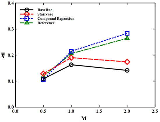
Figure 15.
Area-averaged film cooling effectiveness for the various hole configurations [26].
For M = 0.5, the individual holes show nearly similar levels of cooling performance, but variations emerge from the blowing ratio of 1.0. All modified configurations consistently outperform the Baseline, with the Compound Expansion showcasing an approximately double increase in the film cooling performance. At M = 2.0, both the Baseline and the Staircase show a decline in the cooling performance. However, while the Baseline experiences a 13.3% drop, the Staircase demonstrates an 8.5% decrease. This indicates that, although the Staircase shows a similar tendency in film cooling performance characteristics with the Baseline, it still performs better overall.
Both the Compound Expansion and the optimized hole appear to have an improved film cooling performance under high injection ratio conditions, with the Compound Expansion showing an approximately double enhancement over the Baseline. The results are attributed to the reduced momentum of the coolant by expanding the hole exit for increasing cooling performance. However, the optimized hole shows a lower cooling performance compared to the Compound Expansion, even though it can further reduce the momentum of the coolant through a larger AR. Increasing the area ratio allows for a more uniform protection over a wider region, but excessive expansion angles at the hole exit can induce complex flow behaviors, like separation within the hole, negatively impacting the film cooling performance. Also, in a previous study [26], it was observed that, beyond a certain area ratio, the film cooling performance begins to decline. As a result, the Compound Expansion, with its similar expansion angles to those of the Baseline, experiences less degradation in the film cooling performance due to the separation inside of the hole and, thus, shows a better film cooling performance under high blowing ratios, despite having a lower area ratio.
4. Conclusions
In this study, the adiabatic film cooling effectiveness on a flat plate was measured for different film cooling hole configurations, including the 7-7-7 film cooling hole (Baseline) and modified configurations (Staircase and Compound Expansion). The measurements were conducted using the PSP method, and the film cooling effectiveness was compared in terms of various blowing ratio conditions. When summarizing the results of the adiabatic film cooling effectiveness experiments for each hole, the following findings are obtained.
- The Staircase design features a double-step structure at the hole exit to reduce the coolant separation under high M and improve the coolant distribution.
- The double-step structure was expanded laterally, covering a broader area compared to that covered by the Baseline.
- The Staircase shows less cooling effectiveness decrease due to the lift off effect compared to the Baseline.
- The Compound Expansion hole creates an additional expanded flow passage at the leading edge of the Baseline to dissipate the high-momentum coolant and improve the cooling effectiveness.
- At M = 0.5, an increased inflow and mixing effects cause a decrease in the cooling performance compared to the Baseline. However, at M ≥ 1.0, this issue diminishes, and the additional expanded flow passage significantly enhances the cooling performance by maintaining the injected coolant downstream.
- The improved cooling performance with the additional flow passage can be up to two times better than that of the Baseline, particularly at high M conditions.
As a result, a comparative analysis was conducted on the modified cooling holes based on the 7-7-7 fan-shaped film cooling hole, and it was observed that all the modified configurations showed improvements compared to the Baseline. However, it is important to note that these results are limited to improving the cooling performance on a flat plate. When the modified cooling holes are applied in an actual turbine blade or endwall, it remains uncertain whether the cooling performance will improve under the complex flow conditions within the turbine passage. In future research, we plan to apply the cooling holes studied in this research to the turbine endwall to investigate whether the cooling performance remains effective under the complex flow conditions within the turbine passage.
Author Contributions
Conceptualization, S.K. and D.-H.R.; methodology, S.K., D.L. and D.-H.R.; software, S.K. and Y.S.K.; validation, S.K., D.L., Y.S.K. and D.-H.R.; formal analysis, S.K. and D.-H.R.; investigation, S.K. and D.-H.R.; resources, S.K. and D.-H.R.; data curation, S.K.; writing—original draft preparation, S.K.; writing—review and editing, Y.S.K. and D.-H.R.; visualization, S.K.; supervision, Y.S.K. and D.-H.R.; project administration, D.-H.R.; funding acquisition, D.-H.R. All authors have read and agreed to the published version of the manuscript.
Funding
This research was funded by the Defense Rapid Acquisition Technology Research Institute (grant number: UC190008D).
Data Availability Statement
Data are contained within this article.
Conflicts of Interest
The authors declare no conflict of interest.
Nomenclature
| A | Hole cross-sectional area |
| AR | Area ratio of the outlet to inlet |
| D | Hole diameter |
| DR | Density ratio of the coolant to mainstream |
| h | Step height |
| I | Light intensity |
| L | Hole length |
| Lc | Length of the cylindrical hole section |
| M | Blowing ratio of the coolant to mainstream |
| Ma | Mach number |
| P | Pressure |
| s | Step length |
| T | Temperature |
| Tu | Turbulence intensity |
| t | Hole breakout width |
| u | Local streamwise velocity |
| Umain | Mainstream velocity |
| Wa | Lateral expansion angle of the additional flow passage |
| Wd | Diameter of the additional flow passage |
| x | Downstream distance from the hole trailing edge |
| y | Vertical distance from the surface |
| z | Pitch-wise distance from the center hole |
| Greek symbols | |
| α | Injection angle |
| β | Forward expansion angle |
| γ | Lateral expansion angle |
| ρ | Fluid density |
| η | Adiabatic film cooling effectiveness |
| ω | Molecular weight |
| subscripts | |
| coolant | Coolant flow |
| main | Mainstream |
| aw | Adiabatic wall |
| inlet | Inlet plane of the film cooling hole |
| exit | Exit plane of the film cooling hole |
| ref | Reference |
| superscripts | |
| Laterally averaged | |
| Area-averaged | |
References
- Bogard, D.G.; Thole, K.A. Gas Turbine Film Cooling. J. Propuls. Power 2006, 22, 249–270. [Google Scholar] [CrossRef]
- Goldstein, R.J. Film Cooling. Adv. Heat Transf. 1971, 7, 321–379. [Google Scholar]
- Haruyuki, T.; Chiyuki, N.; Syu, F.; Yasuhiro, A.; Masato, I. Development of Simple and High Performance Technology for Turbine. IHI Eng. Rev. 2008, 41, 20–31. [Google Scholar]
- Bunker, R.S. A Review of Shaped Hole Turbine Film Cooling Technology. J. Heat Transf. 2005, 127, 441–453. [Google Scholar] [CrossRef]
- Ekkad, S.V.; Han, J.C. A Review of Hole Geometry and Coolant Density Effect on Film Cooling. In Proceedings of the ASME Summer Heat Transfer Conference, Minneapolis, MN, USA, 14–19 July 2013; ASME Paper No. HT2013-17250. p. V003T020A003. [Google Scholar]
- Haydt, S. Cooling Effectiveness for a Shaped Film Cooling Hole at a range of Compound Angles. In Proceedings of the ASME Turbo Expo 2018, Oslo, Norway, 11–15 June 2018. ASME Paper No. GT2018-75726. [Google Scholar]
- Haydt, S.; Lynch, S. Flowfield of a Shaped Film Cooling Hole over a range of Compound Angle. In Proceedings of the ASME Turbo Expo 2018, Oslo, Norway, 11–15 June 2018. ASME Paper No. GT2018-75728. [Google Scholar]
- Schroeder, R.P.; Thole, K.A. Adiabatic Effectiveness Measurements for a Baseline Shaped Film Cooling Hole. In Proceedings of the ASME Turbo Expo 2014, Düsseldorf, Germany, 16–20 June 2014. ASME Paper No. GT2014-25992. [Google Scholar]
- Park, S.H.; Kang, Y.J.; Seo, H.J.; Kwak, J.S.; Kang, Y.S. Experimental optimization of a fan-shaped film cooling hole with 30 degrees-injection angle and 6-hole length-to-diameter ratio. Int. J. Heat Mass Transf. 2019, 144, 118652. [Google Scholar] [CrossRef]
- Wang, H.; Wright, L.M. Effect of Inlet Geometry on Flat Plate, Film Cooling Effectiveness from Shaped Holes. In Proceedings of the ASME 2021, Online, 1–5 November 2021. ASME Paper No. IMECE2021-73135. [Google Scholar]
- Elyas, A.; Kusterer, K.; Bohn, D.; Sugimoto, T.; Tanaka, R.; Kazari, M. The NEKOMIMI Cooling Technology: Cooling Holes with Ears for High-Efficient Film Cooling. In Proceedings of the ASME Turbo Expo 2011, Vancouver, BC, Canada, 6–10 June 2011. ASME Paper No. GT2011-45524. [Google Scholar]
- Okita, Y.; Ideta, T.; Fujimoto, S. Multi-Objective Shape Optimization of Arrowhead-shaped Film Cooling Hole on Transonic Turbine Blade. In Proceedings of the ASME Turbo Expo 2020, Online, 21–25 September 2020. ASME Paper No. GT2020-14721. [Google Scholar]
- Lu, Y.; Dhungel, A.; Ekkad, S.V.; Bunker, R.S. Effect of Trench width and depth on film cooling from cylindrical holes embedded in trenches. ASME J. Turbomach. 2009, 131, 011003. [Google Scholar] [CrossRef]
- Oguntade, H.I.; Andrews, G.E.; Burns, A.D.; Ingham, D.B.; Pourkashanian, M. Improved trench film cooling with shaped trench outlets. ASME J. Turbomach. 2013, 135, 021009. [Google Scholar] [CrossRef]
- Abdeh, H.; Barigozzi, G.; Zamiri, A.; Chung, J.T. PSP and LES Investigation on the Impact of Trench Depth on Flat Plate Film Cooling through Shaped Holes. In Proceedings of the ASME Turbo Expo 2023, Boston, MA, USA, 26–30 June 2023. ASME Paper No. GT2023-102890. [Google Scholar]
- Kim, G.M.; Kim, Y.J.; Kwak, J.S. Improvement of Film Cooling Performance of a Slot on a Flat Plate Using Coanda Effect. KSFM J. Fluid Mach. 2017, 20, 5–10. [Google Scholar] [CrossRef]
- Benabed, M. Computational Optimization of Coanda Effect on Film-Cooling Performance. J. Thermophys. Heat Transf. 2015, 29, 757–765. [Google Scholar] [CrossRef]
- Zhang, S.; Zhang, J.; Tan, X. Improvement on shaped-hole film cooling effectiveness by integrating upstream sand-dune-shaped ramps. Chin. J. Aeronaut. 2021, 34, 42–55. [Google Scholar] [CrossRef]
- Fox, D.W.; Furgeson, M.; Flachs, E.M.; Bogard, D.G. Experimental Study of Compressible Film Cooling Scaling and Hole Geometry. In Proceedings of the ASME Turbo Expo 2023, Boston, MA, USA, 26–30 June 2023. ASME Paper No. GT2023-104038. [Google Scholar]
- Kim, S.; Lee, D.-E.; Chung, H.; Kang, Y.S.; Rhee, D.-H. Experimental study on film cooling effectiveness downstream of fan-shaped film cooling holes with staircase geometry at hole exit. KSFM J. Fluid Mach. 2021, 24, 5–14. [Google Scholar] [CrossRef]
- Kim, S.; Lee, D.-E.; Kang, Y.S.; Rhee, D.-H. Experimental Study of Film Cooling Effectiveness Enhancement using Fan-shaped Cooling Holes with Compound Expansion Configuration. In Proceedings of the Asian Congress on Gas Turbines 2022, Gangneung, Republic of Korea, 24–26 August 2022. [Google Scholar]
- Zhang, L.J.; Jaiswal, R.S. Turbine Nozzle Endwall Film Cooling Study Using Pressure-Sensitive Paint. J. Turbomach. 2001, 123, 730–735. [Google Scholar] [CrossRef]
- Zhang, L.J.; Moon, H.K. Turbine Nozzle Endwall Inlet Film Cooling-The Effect of a Backward Facing Step. In Proceedings of the ASME Turbo Expo 2003, Atlanta, GA, USA, 16–19 June 2003. ASME Paper No. GT2003-38319. [Google Scholar]
- Han, J.C.; Rallabandi, A.P. Turbine Blade Film Cooling using PSP Technique. Front. Heat Mass Transf. 2010, 1, 13001. [Google Scholar] [CrossRef]
- Natsui, G.; Little, Z.; Kapat, J.S.; Dees, J.E.; Laskowski, G. A Detailed Uncertainty Analysis of Adiabatic Film Cooling Effectiveness Measurements Using Pressure-Sensitive Paint. J. Turbomach. 2016, 138, 081007. [Google Scholar] [CrossRef]
- Seo, H.J.; Park, S.H.; Kwak, J.S.; Kang, Y.S. Experimental and Numerical Study on the Effect of Fan-Shaped Hole Configuration on Film Cooling Effectiveness. In Proceedings of the ASME Turbo Expo 2019, Phoenix, AZ, USA, 17–21 June 2019. ASME Paper No. GT2019-90817. [Google Scholar]
Disclaimer/Publisher’s Note: The statements, opinions and data contained in all publications are solely those of the individual author(s) and contributor(s) and not of MDPI and/or the editor(s). MDPI and/or the editor(s) disclaim responsibility for any injury to people or property resulting from any ideas, methods, instructions or products referred to in the content. |
© 2023 by the authors. Licensee MDPI, Basel, Switzerland. This article is an open access article distributed under the terms and conditions of the Creative Commons Attribution (CC BY) license (https://creativecommons.org/licenses/by/4.0/).