1. Introduction
Changes in the structure of the generation system, the continuous increase in the demand for electrical energy, and the common concentration of generation capacity (e.g., in the form of offshore wind farms) result in changes in power flow and, consequently, in an increase in the load on the transmission network. This can lead to network constraints. To avoid these limitations, building a significant number of new line connections and power substations is necessary. A significant expansion of the transmission system would guarantee power flow through many independent connections. However, this is not entirely achievable due to economic, social, and environmental conditions. In particular, the issue of common social anxiety against the impact of the electromagnetic field generated by transmission lines is troublesome, manifested by numerous protests and, as a result, delays in the planned development works of the network. On the other hand, from the outlined perspective, there is an indisputable need to ensure the safe operation of the power system. For this reason, in the first step, several actions have been taken to increase the transmission capacity of the existing network infrastructure (replacement of conductors with high-temperature low-sag conductors [
1] or the use of the dynamic load capacity of transmission lines [
2]). Nevertheless, although effective, these methods are insufficient in the long term.
Transmission system operators (TSOs) are still looking for a solution that minimizes negative investment issues and, simultaneously, ensures the sufficiency and flexibility of transmission systems in the long term, while offering a solution that is acceptable to the public. One solution is to use high-voltage direct-current (HVDC) lines [
3,
4,
5]. Currently, they are more often used in point-to-point configurations and connect two selected nodes in the power system. This technology provides the TSOs with an advantageous tool for controlling power flows, including eliminating network constraints or reducing total power losses. Despite the trend of development of HVDC lines, high-voltage alternating-current (HVAC) lines will primarily continue to be the basis for modern power systems, which is why the use of MMOLs is also a reasonable solution. MMOLs are HVAC overhead transmission lines with at least two circuits running on a common supporting structure with different rated voltages.
The main advantages of MMOLs include the following:
the intensification of the use of land occupied by the overhead lines, including improving the expansion of the transmission and distribution network—the dynamic development of these networks (
Figure 1),
reducing the impact of elements of the transmission and distribution network on the landscape and the natural environment by:
the possibility of reducing the maximum values of the electromagnetic field strength in the vicinity of overhead lines (OLs),
the reduction of the number of supporting structures,
the reduction of deforestation,
facilitating the laying of OLs in areas that are difficult to develop (for example, heavily urbanized areas with a high density of buildings, forests, and mountains).
MMOLs are found all over the world, but their share in network structures is not currently dominant, so current problems relating to their use are often ignored. However, due to the continuous development of this solution, special attention should be paid to the challenges and risks posed by their use, which include (among others):
the need to use dedicated supporting structures,
the risk of intersystem disturbances, including the complication of algorithms for the operation of power protection automatics,
difficult maintenance, including live maintenance,
geometric asymmetry affecting the operation of the OL and network environment—the interaction of circuits with different rated voltages,
complex mathematical models that describe MMOLs (models taking into account the multitude of couplings and interactions resulting from the presence of many circuits and the diversity of their rated voltages).
The literature deals with selected aspects relating to the operation of MMOL. The vast majority of publications refer to research on the impact of the electromagnetic field in its vicinity [
6,
7,
8,
9,
10,
11,
12], where, among others, they present methods that ensure the lowest possible values of the electromagnetic field strength, which is achieved using modern constructions of poles or an appropriate configuration of phase conductors in circuits. Analysis of the impact of the electric field strength that affects workers, who perform operational and repair work on the supporting structure, is also carried out. As a result, a greater impact was identified in the case of work at a circuit with the lowest-rated voltage due to the additional impact of the electric field from circuits with higher voltages. However, it is noted that the operational risk is insignificant at any location of a man on a pole [
12]. Aspects relating to modeling and determining electrical parameters of OL have been extensively described, for example, in refs [
13,
14,
15,
16,
17,
18,
19,
20,
21,
22,
23].
In terms of MMOL modeling, the most common practice today is the use of simulation programs to study transient states, where the OL model is generated for simulation purposes [
14,
24]. Several publications deal with the subject of transient states that occur in MMOLs as a result of, for example, interactions of adjacent current circuits, ferroresonance phenomena, the operation of earthing switches, and the operation of automatic power protection (e.g., distance and ground-fault protection and the occurrence of disturbances between systems) [
25,
26,
27,
28,
29,
30]. Only a few articles [
31,
32] directly describe the algorithm for determining the electrical parameters of MMOL for steady-state studies. In addition, scientific papers on the subject of MMOL in normal operating states are limited to the analysis of one type of phenomenon, focusing on selected MMOL constructions [
25,
33,
34,
35,
36,
37]. The asymmetry of voltages and currents in the system introduced by MMOLs is also analyzed [
38,
39,
40,
41]. This type of dependence in MMOLs is also described in refs [
42,
43]. Nevertheless, so far, the impact of MMOL design diversity and its influence on network operation have not been described from a broader perspective.
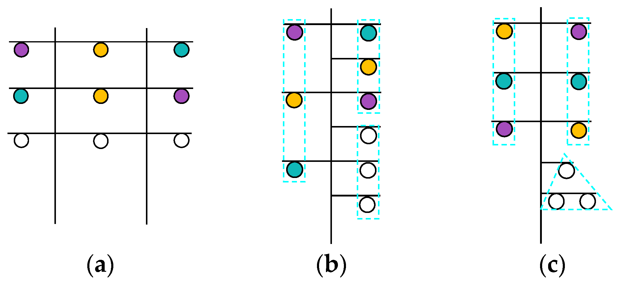
The examples of MMOLs structures in Europe are characterized by the significant diversification of the degree of geometric asymmetry. There are variants of all the methods of laying circuits, that is, combinations of flat and triangular arrangements (
Figure 2a), vertical arrangements (
Figure 2b), etc. There are often solutions where phase conductors belonging to circuits with different rated voltages are run on a common crossarm (
Figure 2c). The maintenance of insulation distances is a particularly important issue in this case.
Running several circuits with different rated voltages on a common structure is associated with the occurrence of mutual interactions of these circuits with each other. These interactions, due to the geometrical asymmetry of OLs, are the cause of many threats that occur in the normal operating states of the transmission network. Therefore, threats and risks result from the impedance and capacitance asymmetry introduced by MMOLs. So far, simplified mathematical models of these lines have been used, assuming their electrical symmetrization and the possibility of describing them by specifying parameters for symmetrical components. The increase in the share of MMOLs in power system structures and the existing operational needs require an appropriate mapping of the phenomena resulting from the presence of MMOLs and ensuring electrical energy quality in transmission networks’ co-operation with these lines. Therefore, the potential threats affecting the nearest network surroundings resulting from the operation of MMOLs, discussed in this article, include:
occurrence of dangerously high neutral point displacement voltage of the network with the lowest-rated voltage (zero voltage, U0) resulting from the capacitance asymmetry introduced by MMOLs,
the risk of exceeding the permissible values of unbalance and asymmetry factors, regulated by national regulations resulting from impedance asymmetry of the MMOLs,
the risk of the incorrect determination of short-circuit currents in systems co-operating with MMOLs due to the use of a simplified (symmetrical) mathematical model of this line.
The different arrangements of circuits on the poles and the phase conductor configuration in individual circuits influence the three risks presented above. By changing the geometry of MMOLs, it can be expected that the level of these threats will change, but improving one of them may worsen the others. The authors are looking for an MMOL geometry that will ensure the optimal levels of the mentioned threats to meet the requirements of properly balanced power networks.
The main purpose of this paper is to present the results of the analysis that will allow us to identify the effects of the geometrical asymmetry of MMOLs that affect the operation of the transmission network and to propose methods to minimize these effects.
To achieve this objective, the authors developed a universal mathematical model of MMOLs [
31], indicated the greatest threats to the power system caused by the presence of MMOLs and defined quantities that describe these threats (
Section 2.2.1), and developed analysis scenarios (
Table 1), which allowed the overall optimization of the defined quantities, thus mitigating the risks associated with the operation of MMOLs in the network. Finally, the authors verified the proposed method on a fragment of the real transmission network in Poland.
2. Methodology
2.1. Background of the Issue
A large group of double-circuit, three-circuit, and four-circuit lines were tested with different configurations of laying the circuits on the pole and combinations of their rated voltages. Analysis of the operation of these MMOLs allowed one to observe that the circuit with the lowest-rated voltage is most often mainly exposed to the effects of geometric asymmetry [
32,
43,
44].
This is justified for several reasons. The MMOL capacitance asymmetry results in the appearance of the zero-sequence voltage, U0, in the unenergized circuit. Mutual capacitances are fixed and unchangeable, but the voltage U0 is analyzed by referring its value to the rated voltage level Un of the tested circuit. Thus, referring the value of voltage U0 to the level of Un with a lower value accounts for a greater contribution than in the case of referring this voltage to a higher value of Un. The MMOL circuit with the lowest-rated voltage level is, therefore, most exposed to exceeding the permissible operating voltage levels. The voltage level of U0 is also significantly affected by the phase voltages of the remaining circuits (in particular, circuits with voltages higher than the rated voltage of the tested circuit).
The second reason is related to the MMOL operating conditions and, more precisely, to the values of the load currents of individual circuits. The mutual reactance between a pair of circuits is the same (as are the mutual capacitances), but the currents in the circuit of lower-rated voltage level are usually lower than the currents in the circuits with higher voltages (which results, for example, from line current-carrying capacities). Therefore, despite the same mutual impedance between the circuits, the interactions will be different. For example, because the currents in the 400 kV circuit are higher, these currents cause a greater voltage drop in the 110 kV circuit (relating to the given component) than the currents of the 110 kV circuit in the 400 kV circuit.
Based on the observations and justification presented above, the effects of MMOLs are analyzed by paying particular attention to the operating conditions of the circuit with the lowest-rated voltage, because they determine the criteria values within individual analyses.
A phase-symmetrical OL is described by the admittance matrix for the phase quantities
Y and the block diagram (
Figure 3). This model is used for steady-state and quasi-steady-state analyses for the purposes of, among others: power load flow, development analyses of the transmission network, determination of the initial symmetrical short-circuit current, analysis of the selection of the cross-section of lightning conductors, etc. This type of model is often used in commercial software, among others, DIgSILENT PowerFactory in steady-state analyses. The method of determining the parameters of the
Y admittance matrix of an OL is discussed, among others, in refs [
13,
14,
31,
45].
The model of
n-circuit OL is complex and contains (2·3·
n)
2 non-zero elements, where
n is the number of circuits of the
n-circuit line. Therefore, the preferred model of OL is the admittance matrix of symmetrical components
YS, in which the lines’ positive, negative, and zero admittances are distinguished. In the case of a phase-symmetrical line, the
Y matrix is described according to the following expressions:
where
Yr signifies the series admittance,
G is the shunt conductance,
C is the capacitance,
ω = 2π
f, in which
f is the network frequency,
si.j is a subscript that indicates the symmetrical component (in which zero—0, positive—1, or negative—2) for circuit
i or pair of circuits
i and
j, and
i,
j ∈ {I, II, …,
n}.
This form of the admittance matrix (1–2) is a sparse matrix that enables the extraction of three independent models for each symmetrical component. Thus, for a symmetrical line, the positive and negative component models correspond to the independent circuit models. The zero-component model contains the connections of all line start-nodes and end-nodes. Capacitances are concentrated at the beginning and end of the line and occur between individual circuits, and between a given circuit and the ground. The method of determining the parameters of the MMOL admittance model is presented in detail in ref. [
31].
It is assumed that natural phase symmetry occurs for a single-circuit line when the line conductors are run in an equilateral triangle (which is an approximation due to different capacitance values for each phase conductor). For the remaining cases, i.e., the multi-circuit lines, the individual distances between the line conductors are not the same and, therefore, the respective impedances and capacitances of the conductors are varied, which is reflected in the admittance matrix values. The asymmetrical MMOL is described by the full admittance matrix of the symmetrical components
according to the following relationship:
For this form of the model, corresponding to Equation (3), all elements of the matrix are non-zero (a total of (2·3·n)2 non-zero elements). Thus, the structure of the matrix of symmetrical components YS that describes the asymmetric line is the same as the structure of the phase quantity model (the full matrix) Y. It follows that, contrary to the model for symmetrical lines, this form does not allow the use of the advantages of transforming the model from phase quantities to symmetrical components. Each of the symmetrical components of voltages and currents is a function of not only one particular component but is also dependent on the other symmetrical components. Reflected in this model, the connections that occur for real asymmetrical MMOLs are the causes of many of the previously mentioned negative phenomena resulting from their geometric asymmetry.
2.2. Method of Reducing the Effects of Asymmetry
The method resulting in minimizing the effects of geometric asymmetry of the MMOLs is divided into two steps:
selection of silhouette characterized by a small degree of geometric asymmetry,
(if still necessary) partial MMOL symmetrization.
The identification of MMOL silhouettes characterized by a small degree of geometric asymmetry is valuable information at the stage of designing new line connections in the transmission network. The choice of a silhouette with a small geometric asymmetry, and, thus, is close to the ‘ideal’ understood here as a phase-symmetrical line, limits the effects of the MMOL asymmetry in the analyzed system. The search for such structures is performed in the symmetrical network surroundings. This approach works effectively in real network development analyses because the selection of the structure of its individual elements, such as the silhouette, phase configuration, etc., is optimized each time in terms of maintaining the permissible operating and quality parameters. In effect, such systems meet the requirements of the relevant standards and regulations, for instance, the grid and distribution codes. The introduction of an MMOL with a significant degree of geometric asymmetry to the operation would involve the need to perform many additional and expensive undertakings to fulfill the applicable standards.
The approach proposed by the present authors enables a limiting of the selection of MMOL silhouettes to those whose geometrical asymmetry has the least impact on the existing network surroundings (maintaining acceptable quality parameters of electrical energy, safety, etc.). If necessary, the next step is to perform phase symmetrization of the line that, as a result of the use of a favorable silhouette in the first step (with a small degree of geometric asymmetry), can be executed partially, thus covering one circuit of an MMOL. This method requires less investment and technical effort than the full symmetrization of the MMOL (over its entire length). This analysis is performed in the real asymmetric network surrounding the newly created MMOL.
2.2.1. Step I: Selecting a Silhouette of the MMOL
The analysis of the search for the MMOL silhouette characterized by a small degree of geometric asymmetry is carried out in the symmetrical network surroundings. The present authors modeled the MMOL external system as a symmetrical equivalent source from the MMOL supply side and symmetrical constant impedance loads from the load side of the MMOL. The analyzed system is parameterized in such a way as to load the lines with the multiplicity of the long-term permissible currents of individual circuits. The following three criteria are considered for evaluating the geometric asymmetry of the MMOL:
Due to the presence of capacitance asymmetry, the supply of the selected MMOL circuit (circuit with higher-rated voltages) with symmetrical voltage causes the creation of non-zero asymmetric potentials on the conductors of the disconnected circuit (in this case, the circuit with the lowest-rated voltage—circuit
n). Summing up the circuit
n potentials generated within a circuit provides the value of triple the zero-sequence voltage
U0 in this circuit according to:
where
Ui denotes the column of phase voltages of the circuit
i,
i ∈ {I, II, …,
n},
Cn.n is the matrix of self and mutual capacitances of circuit
n,
Cn.(n−1) is the matrix of mutual capacitances of
n and (
n − 1) circuits, and
U0 is the neutral point displacement voltage of the network co-operating with circuit
n, also the zero-sequence voltage of this circuit.
The unacceptably high voltage U0 is a serious problem in terms of the operation of ground-fault protections and the occurrence of significant zero-sequence currents in normal operating states of the transmission network. Equally important is the issue of safety and the real risk of electric shock during live maintenance, i.e., maintenance activities carried out while the associated circuits are energized.
- 2.
Zero- and negative-sequence voltage factors during normal MMOL operation (voltage asymmetry factors α0 and α2, also called voltage quality factors).
Two of the parameters that characterize the quality of electrical energy are the zero-sequence voltage factor
α0 (also known as unbalance factor) and the negative-sequence voltage factor
α2 (called the asymmetry factor) defined according to the relations:
where
U0,
U1, and
U2 are, respectively, the zero-, positive-, and negative-sequence of voltage in the analyzed circuit. Therefore, they determine the content of the zero-sequence and negative-sequence voltage components, here resulting from the impedance asymmetry of the MMOL.
According to Polish regulations, the limit value of the asymmetry factor is 1% [
46]. The same limit value is assumed for the unbalance factor.
- 3.
The level of errors δI% when estimating the value of short-circuit currents using the symmetrical model to describe the phase-asymmetrical MMOL.
The geometric asymmetry of the OL also translates into the values of the expected short-circuit currents of the individual phases of this line. The practical approach used in short-circuit analysis assumes the use of a symmetrical model of OL. In the symmetrical model, the single-phase short-circuit currents are the same for different phases, and the same currents flow during the three-phase faults in each phase. In MMOLs that are characterized by significant impedance asymmetry, as a result of a three-phase fault, a different current may flow in each phase, and the single-phase fault current depends on the phase in which it occurred.
Due to the conclusions presented from the observations regarding the significant asymmetry of the MMOLs, the purpose of the analysis is to assess the impact of the type of MMOL model used in short-circuit modeling and calculations. As part of the short-circuit analysis, the single-phase and three-phase short-circuit currents in the system with the analyzed MMOL are determined by estimating the errors using a simplified (symmetrical) model of the line. Short-circuit currents are analyzed at the location of their occurrence, i.e., at the end of the circuit with the lowest-rated voltage. The shares of the short-circuit current from the side of the MMOL circuit affected by the fault are also tested. The indicators of the impact of the type of MMOL model used are the relative percentage errors defined according to:
where the superscripts s and as denote, respectively, the
I currents determined using the symmetrical and exact (asymmetrical) models, the fault subscript represents the determination of the parameter (current
I or error value
δI%) at the fault location, and the branch subscript symbolizes the determination of the parameter (current
I or error value
δI%) relating to the short-circuit current in the circuit affected by the fault.
The most important features of an MMOL with a small degree of geometric asymmetry (i.e., a line whose impedance and capacitance asymmetry resulting from its geometry do not result in significant levels of the established criterion values) include the following:
the U0 voltage value in the circuit with the lowest-rated voltage does not exceed 5% of the rated voltage of this circuit,
the unbalance and asymmetry factors are less than 1% for an MMOL with a length of at least 75 km (average length of transmission line in Poland),
the relative percentage errors when determining short-circuit currents using a symmetrical model do not exceed|±5%|.
To identify MMOLs characterized by a small degree of geometric asymmetry, the scoring method was used. The MMOL silhouette is evaluated within the analyses presented in
Table 1.
The criterion values indicated in
Table 1 are compared within the group of tested MMOL-supporting structures. Based on the results of comparing the results obtained by the MMOLs tested in individual analyses, in each of them, silhouettes are selected that meet the specified criteria to the greatest extent. These supporting structures are called ‘the best’, that is, with a small degree of geometric asymmetry.
Furthermore, the authors selected from the group of MMOL silhouettes that did not meet the criteria presented to the greatest extent within individual analyses. These supporting structures are called ‘the worst’, that is, with a high degree of geometric asymmetry. Selected scoring results are presented in
Section 3.1.
2.2.2. Step II: Symmetrization
Another path leading to the reduction of the effects of the geometric asymmetry of the MMOL affecting the studied criterion quantities is full or partial symmetrization. Symmetrization is understood as the transposition of phase conductors within the MMOL circuit, i.e., changes in the positions of these conductors in relation to each other and, as a result, also to the ground surface and other phase conductors belonging to the remaining circuits of the MMOL.
Figure 4 presents illustrations of six types of transposition that can be made within a single circuit of the OL.
Figure 5 shows an example of full-phase symmetrization of a three-circuit OL. As a result of the full symmetrization of OL, each phase conductor successively occupies, over approximately equal lengths of the route, each geometrical position in the laying configuration. Next, from the general point of view, the MMOL is phase-symmetrical and can be described by a symmetrical model according to Equation (1). However, to obtain full phase-symmetry of the three-circuit OL, 36 transpositions of type (e) or (f) in
Figure 4 should be made at specific, uniform intervals, which are made at 26 locations along the length of the line (2 transpositions in the circuit I, 8 transpositions in circuit II, and 26 transpositions in circuit III), according to
Figure 5. Furthermore, if, at the other end of the OL, it is planned to keep the phase configuration identical to the one at the beginning of the OL, additional 3 transpositions should be made in each of the line circuits (
Figure 5—location marked with number 27). In this case, the following should be performed in total: 3 transpositions in circuit I, 9 transpositions in circuit II, and 27 transpositions in circuit III, while maintaining appropriate equal intervals between individual transpositions.
As can be seen, a full MMOL symmetrization is challenging to implement for technical, logistical, and economic reasons. In particular, for OLs with short lengths (i.e., several kilometers), full symmetrization is impossible.
For the reasons mentioned above, it is, thus, proposed that we perform a partial symmetrization of the line, which is performed by transposition of the phase conductors of the circuit with the lowest-rated voltage, which is the most exposed to threats resulting from the geometric asymmetry of the MMOL. Performing partial symmetrization of the MMOL leads to approaching the ‘ideal’, that is, to a phase-symmetrical OL described by a symmetrical model.
In the case of complete symmetrization of the circuit with the lowest voltage rated, the
YSpt model is obtained from the following:
where
Ysi and
Yssi.j are the admittance of the symmetrical component(s) for circuit
i and circuits
i and
j, respectively, with
i,
j ∈ {I, II, …,
n}, and
s is the symmetrical component with
s ∈ {0, 1, 2}.
In the model relating to expression (10), fragments relating to the symmetrical circuit are simplified (marked in green font). The individual elements of the matrix are observed to have zero value. It is noteworthy that, for the positive-sequence and negative-sequence components associated with circuit n, the elements from other symmetrical components have the value zero and, therefore, do not affect these components. However, for the zero-sequence component, such partial symmetrization leaves non-zero elements of the matrix (marked in red), and only the values of these elements change. As a result, the final form of the zero-sequence component is influenced by other symmetrical components. Such symmetrization does not completely eliminate the effects of interactions resulting from the geometric asymmetry of the MMOL, but it allows for their significant reduction.
Two scenarios for partial MMOL symmetrization should be considered, which are performed in the circuit with the lowest-rated voltage:
transpositions performed in half-length of MMOL (1/2 l)—i.e., single transposition,
transpositions performed in 1/3 length and 2/3 length of MMOL—i.e., double transposition.
It is noted that the minimization of the impact of capacitance asymmetry on the tested circuit with the lowest-rated voltage will not occur as a result of the transposition of this circuit. To reduce the value of the voltage
U0 appearing in this circuit, it is necessary to perform a transposition in other circuits (with the higher-rated voltages) [
31]. This is due to the remaining non-zero elements associated with the symmetrized circuit
n (elements marked red in expression (10)).
2.3. Case Study—Verification of the Proposed Method
To verify the proposed method for minimizing the effects of geometric asymmetry of MMOLs, an analysis of the operation of the three-circuit, two-voltage (2 × 400 + 220 kV) OL in the real transmission network was performed. The analyzed system is shown in
Figure 6. The presented system represents a fragment of the transmission network in Poland. The names of individual power stations have been changed. The MMOL connecting stations A and B, with a length of 75 km, is planned to be introduced into the Polish transmission network in 2032 [
47].
The network surroundings of the MMOL have been limited to power stations where electricity generation is present. Terminal substations were modeled as constant-impedance loads, the parameters of which correspond to actual 400/110 kV and 220/110 kV network transformers. The introduction of MMOL to the presented system results in the power flows shown in
Table 2.
According to the proposed methodology:
An MMOL silhouette characterized by a small degree of geometric asymmetry is proposed,
In the case of exceeding the asymmetry ratios in the tested system, partial phase symmetrization of the MMOL is considered.
4. Discussion
In this paper, the authors defined the method for searching for MMOL-supporting structures, which can be considered symmetrical up to a length of 75 km. The tests of
U0 voltage, and
α0 and
α2 factors, as well as the estimation of errors in determining the short-circuit currents, using a symmetrical model to describe the asymmetrical MMOL, allowed the authors to determine the maximum lengths of the OLs at which the permissible values of the studied criteria were not exceeded. Moreover, the authors determined the configuration of the phase conductors for which the criteria quantity values were the smallest in the analyzed circuits. This approach made it possible to recognize and approximate the phenomena that occur in MMOLs as a result of the mutual interactions of circuits with different rated voltages and various degrees of geometric asymmetry. Based on the developed methodology and performed analyses, MMOL silhouettes were found that were characterized by insignificant geometric asymmetry.
Table 7 presents selected detailed conclusions drawn within the performed analysis that led to the identification of MMOLs with a small degree of geometric asymmetry.
The analysis was performed for a group of several MMOLs. On the basis of the conclusions from the conducted research, it was noticed that the smallest degree of geometric asymmetry was characterized by MMOLs, in which there is an even interaction of the circuits on each other. Such an even interaction occurs in structures with vertical or horizontal circuit arrangements (
Figure 8). Such lines do not introduce significant errors in quasi-steady- and steady-state calculations to a certain OL length. It can be assumed that, for the selected structures up to 75 km in length, the levels of the neutral point displacement voltage, unbalance, and asymmetry factors are also within acceptable limits. Simultaneously, it is noted that the MMOL circuits must be run parallel to each other. In such structures, all circuits interact in an equal way. It is noted that this effect is achieved with the appropriate configuration of phase conductors in each circuit, which should be selected in the destination network system (real, asymmetrical surroundings). The silhouette shown in
Figure 7d is also characterized by parallel running circuits, but the circuits are arranged asymmetrically to each other. This silhouette, according to the scoring method used (
Table 3), received the lowest score. Furthermore, it was noticed that it is advantageous to run circuits with similarly rated voltages in their direct vicinity, that is, a 400 kV circuit next to a 220 kV circuit, or a 220 kV circuit next to a 110 kV circuit (
Figure 8).
A selected group of MMOL structures, which are characterized by a small degree of geometric asymmetry, facilitates the selection of the silhouette of the newly constructed OL. Such an analysis was performed in
Section 2.3. On the basis of the conclusions drawn (
Table 7), silhouette
b (
Figure 7b) with a central symmetry configuration of phase conductors (
Figure 9a) was selected for the next stage of research.
Due to the introduction of an MMOL characterized by a small degree of geometric asymmetry in the tested system, the
α0 and
α2 factors at the B-3 node (220 kV) were slightly exceeded, which was 1.11% (permissible value: 1.00%). For comparison, if an MMOL with a construction analogous to the one presented in
Figure 7d was introduced into the considered system, then the value of the
α2 factor in node B-3 would be approximately three times higher. Moreover, the
α0 factor would be much higher—about ten times higher than in the applied MMOL. This fact confirms the correctness of the adopted methodology for selecting the MMOL structure with a small degree of geometric asymmetry. The correction of the
α2 factor can be made with little effort by applying partial symmetrization of the circuit in which the
α2 factor was exceeded (220 kV network).
Each of the proposed methods of reducing the value of
α2 factor was effective (
Table 6). The
α0 and
α2 factors in each of the examined nodes (also in other nodes of the surrounding network) were within the permissible limits 0–1%. The results presented in
Table 6 refer to the performance of the transposition in a longer section of the MMOL. The authors also performed calculations using transpositions in a shorter section of the newly constructed line (
lX-A,
Figure 6). The proposed methods provide a smaller effect, but the reduction of the
α2 factor to a permissible level was also achieved. This would not be possible for MMOLs with a high degree of geometric asymmetry. The research confirmed the accuracy of the adopted methodology.
5. Conclusions
From the point of view of the external conditions of system development, MMOLs are a very beneficial solution. They are not a source of an increased level of electromagnetic field strength in relation to the values achieved in the case of traditional OLs. Additionally, they allow for a significant reduction in the total route width necessary to run OLs (
Figure 1). Furthermore, the construction of MMOLs enables the effective development of power networks because a single construction of OL acting as MMOLs results in the emergence of many branches in the individual networks co-operating with this MMOL.
The effects of the geometrical asymmetry of the MMOL were observed to the greatest extent in the circuit whose rated voltage is lower in relation to the other circuits. Thus, from the group of transmission MMOLs tested, the most exposed to the effects of the asymmetry of the MMOL was the circuit with a rated voltage of 110 kV, especially in co-operation with the circuit(s) with a rated voltage of 400 kV.
Despite the greatest exposure to the effects of the geometric asymmetry of the circuit with the lowest-rated voltage, the use of simple technical methods such as the transposition of phase conductors of this circuit is easy to implement, for example, due to the high availability of this circuit on the supporting structure or the level of its rated voltage. Partial symmetrization of MMOL makes it possible to minimize the effects and the risk of its asymmetry in the analyzed circuit. As a result, manifested by a decrease in the value of voltage quality factors, it is possible to use a symmetrical model to describe an MMOL and increase its maximum length. Depending on the silhouette, the length-added increase may be made from several to several dozen kilometers while maintaining the values of the permissible criteria.
Based on the performed analyses, it was noticed that a very important aspect in the design of an OL is the geometry of its silhouette, which decisively affects the degree of capacitance and impedance asymmetry, as well as short-circuit calculations. The appropriate selection of the MMOL structure allows for approaching the ‘ideal’, understood as a fully phase-symmetrical line. The use of such an OL silhouette enables a significant minimizing of the effects resulting from the asymmetrical interaction of circuits with different rated voltages on each other, affecting the correct operation of the transmission network.
The next step was partial symmetrization, where the selection of the appropriate transposition is made by analyzing the considered MMOL in its surrounding destination network. Partial phase symmetrization was performed in the circuit most exposed to the effects of geometric asymmetry. The conducted tests confirmed that this was the circuit with the lowest-rated voltage (in the case of more than one circuit with such voltage, it was the circuit that is run closer to the ground surface). To meet the permissible values of the criteria that characterize a symmetrical OL, it was sufficient to make a single transposition along the entire length of the line. The transposition is then performed in the circuit that is the most exposed to the risky operating state, in which the limit value of a criterion has been exceeded.
The MMOL network surroundings, including the network density, the number of independent electricity flow paths, load conditions, and geometric parameters of OL, shape the MMOL operating conditions. The results of the conducted research confirmed the need for an individual approach to the selection of the MMOL structure, including, among others, the configuration of its phase conductors. However, a preferred solution was to use silhouettes with a small degree of geometric asymmetry (identified in this article—
Figure 8) and employ phase conductor configurations in circuits with higher-rated voltages characterized by central symmetry (
Figure 9).
The methodology proposed by the authors allows for finding a compromise between the three analyzed criteria. This is a significant development of the analyses conducted so far, which focused on the optimization of one criterion. The analysis carried out allows for a broader look at the co-operation of MMOLs with the existing transmission network.
In further research, the authors will look for a geometric indicator that will allow for the simple identification of MMOL with a small degree of geometric asymmetry, and they will extend the analyses to include hybrid transmission lines.


