Article

Design and Analysis of an Adaptive Dual-Drive Lift–Drag Composite Vertical-Axis Wind Turbine Generator

School of Mechanical Engineering, North University of China, Taiyuan 030051, China
*
Author to whom correspondence should be addressed.
Energies 2023, 16(22), 7529; https://doi.org/10.3390/en16227529
Submission received: 16 October 2023 / Revised: 4 November 2023 / Accepted: 6 November 2023 / Published: 11 November 2023
(This article belongs to the Special Issue Wind Turbines, Wind Farms, and Wind Energy: 2nd Edition)

Abstract

:
In this paper, based on the lift-type wind turbine, an adaptive double-drive lift–drag composite vertical-axis wind turbine is designed to improve the wind energy utilization rate. A drag blade was employed to rapidly accelerate the wind turbine, and the width of the blade was adaptively adjusted with the speed of the wind turbine to realize lift–drag conversion. The aerodynamic performance analysis using Fluent showed that the best performance is achieved with a blade curvature of 30° and a drag-type blade width ratio of 2/3. Physical experiments proved that a lift–drag composite vertical-axis wind turbine driven by dual blades can start when the incoming wind speed is 1.6 m/s, which is 23.8% lower than the existing lift-type wind turbine’s starting wind speed of 2.1 m/s. At the same time, when the wind speed reaches 8.8 m/s, the guide rail adaptive drag-type blades all contract and transform into lift-type wind turbine blades. The results show that the comprehensive wind energy utilization rate of the adaptive dual-drive lift–drag composite vertical-axis wind turbine was 5.98% higher than that of ordinary lift-type wind turbines and can be applied to wind power generation in high-wind-speed wind farms.

1. Introduction

In the past few decades, with the increasing use of fossil fuels, the greenhouse effect and climate change have become more and more significant, and so the demand for renewable energy continues to increase. Wind energy is one of the cheapest forms of green energy [1]. As a clean power generation method [2], wind power generation can convert wind energy into electricity. According to the direction of the rotation axis, turbines can be divided into horizontal-axis wind turbines (HAWTs) and vertical-axis wind turbines (VAWTs). However, although VAWTs are less efficient compared with HAWTs [3], they have their own unique advantages, such as a simple structural design, the ability to operate with any direction of wind flow, and the lack of a yaw mechanism [4]. In addition, VAWTs are easy to manufacture, install, and maintain [5,6]. Therefore, in recent years, the development of vertical-axis wind turbines has rapidly progressed, and related research and applications have increased year by year [7]. In general, VAWTs can be further divided into drag-based VAWTs (Savonius) and lift-based VAWTs (Darrieus). These two types of wind turbines capture wind energy through drag or lift [8].
Generally speaking, a drag-type Savonius wind turbine is less efficient than a lift-type Darrieus wind turbine [3], but its start-up performance is excellent. However, Darrieus wind turbines have a higher wind energy utilization rate, which is suitable for large-scale installations for wind power generation [3]. Many researchers have confirmed that Savonius drag blades can improve the start-up performance of lift wind turbines at low wind speeds, but they will lead to wind stall at high tip speed ratios [9]. In order to widen their applicability, many scholars have devoted themselves to combining the advantages of these two types of wind turbines to reduce the start-up wind speed and improve the wind energy utilization rate.
In the past few decades, many scholars have improved the efficiency of vertical-axis wind turbines through structural design, airfoil optimization, and fluid analysis. Some scholars reduced the starting wind speed of a Savonius wind turbine by employing jet pipes and installing deflector plates [10,11,12,13]. Bhayo et al. [14] showed that the performance of an improved two-blade single-stage conventional rotor was 47% higher than that of a conventional rotor after studying different blade designs, numbers of blades, and stages. Masoumeh Gharaati et al. [15] found through numerical simulation that if the torsion direction of the spiral blade changes, the influence of the spiral blade on the wake characteristics will be reversed. Zamani et al. [16,17] designed a J-shaped blade that can benefit from both lift and drag, and numerical simulation analysis showed that the self-starting performance of the J-shaped blade is better. Wang et al. [18] also designed a new Darrieus vertical-axis wind turbine, and the results show that the new adaptive blade can significantly suppress flow separation on the blade surface. Chen et al. [19] used blade openings to improve the performance of a Darius wind turbine, and the simulation results showed that the modified blade shape had a better self-starting performance and wind energy utilization.
Sengupta et al. [20] studied the influence of the curvature and curvature on a vertical-axis wind turbine with asymmetric blades to improve the aerodynamic performance of the small VAWT. Sun Xiaojing [21] et al. designed a lift–drag composite vertical-axis wind turbine by combining the advantages of the two types of wind turbines. The simulation results show that the installation position of the drag blade has a great influence on the power coefficient and starting torque. Hosseini et al. [22] modeled and analyzed a hybrid VAWT and showed that the hybrid wind turbine has a good self-starting ability, and the maximum utilization rate of wind energy is 48.4% when the tip speed ratio is 2.5. In order to improve the starting performance of lift–drag composite VAWTs, Fang Feng et al. [23] designed a lift–drag composite starter for lift–drag vertical-axis wind turbines.
Through continuous research, it has been shown that the installation position of the drag blade in a lift wind turbine has a great impact on the aerodynamic performance. If the drag blades are installed near the main axis, the start-up performance of lift-and-drag composite vertical-axis wind turbines may not be improved [21]. Moreover, the lift–drag composite vertical-axis wind turbines in most of the above studies were mostly based on static designs, and the moment of inertia of the wind turbine was ignored. Although the start-up characteristics of wind turbines have been improved, wind turbines with an additional drag-type blade are prone to stalling, which also leads to lower wind energy utilization and poor aerodynamic performance, ignoring the dynamic changes in the lift and drag. Many scholars have considered the moment of inertia in studying the vibration characteristics of wind turbines during operation.
In order to improve the performance of lift–drag composite vertical-axis wind turbines, this study comprehensively considered the rotation characteristics of lift–drag composite vertical-axis wind turbines and modified an existing drag-type blade. Using a rail-type adaptive drag blade as the drag-type dual-drive blade can rapidly accelerate the composite wind turbine; that is, rail-type adaptive drag blades occupy two-thirds of the area between the main shaft and the lift-type blade, and the airflow can pass through the hollow part smoothly, forming the drag-type dual-drive blade.

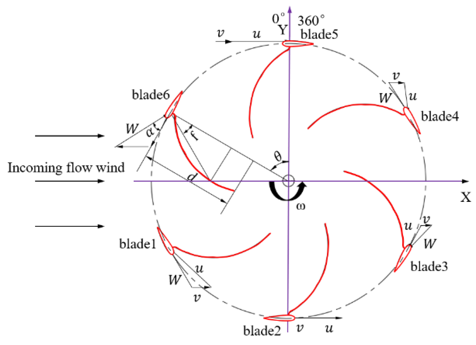
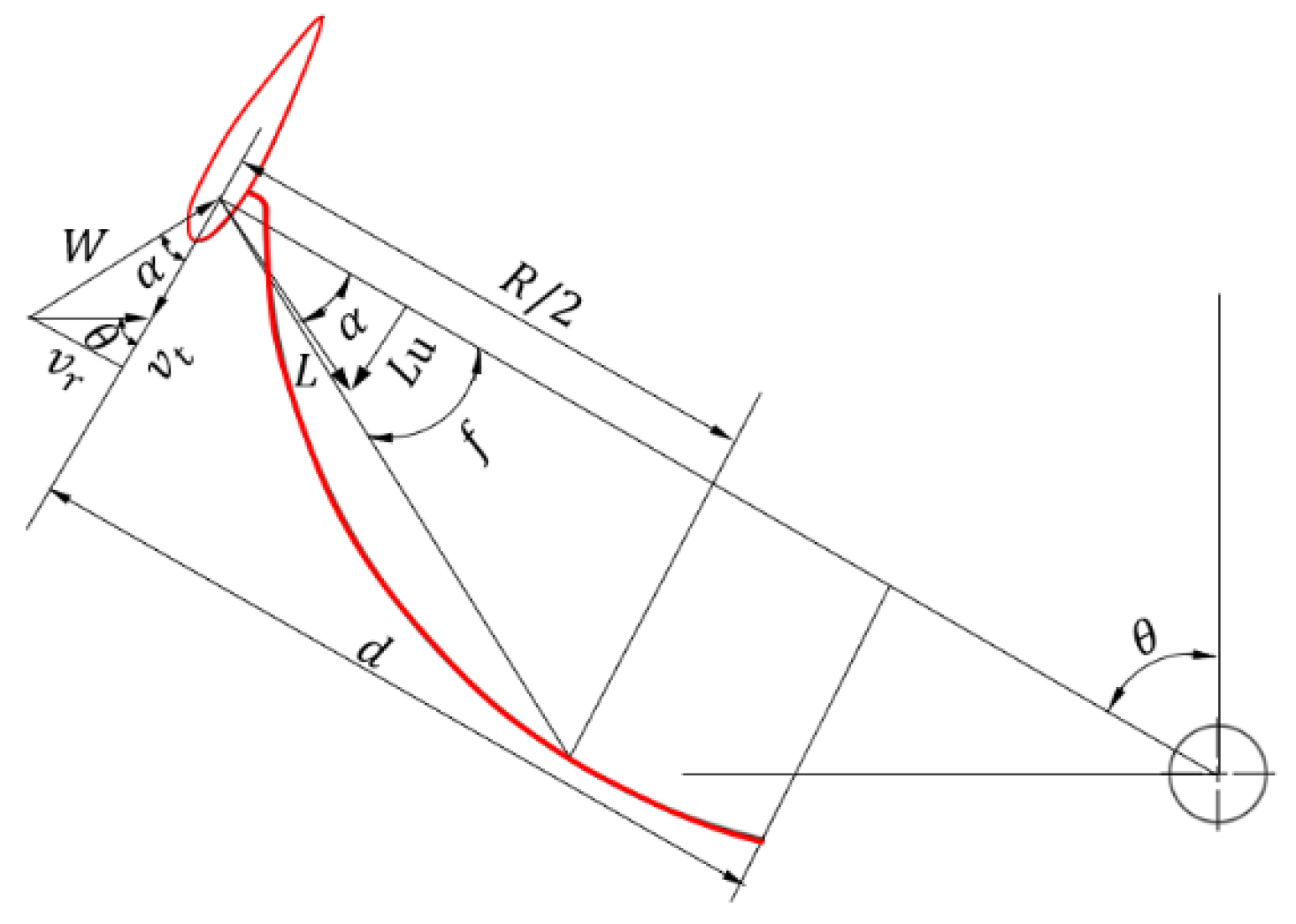
2. Model and Parameter Definitions

The adaptive dual-drive lift–drag composite vertical-axis wind turbine designed in this article mainly includes drag-type and lift-type blades. The drag-type blades, due to the action of centrifugal force, can adaptively adjust the blade width with changes in wind turbine speed. The theoretical and physical models developed using Solidworks to model the adaptive dual-drive lift–drag composite vertical-axis wind turbine are shown in Figure 1. The NACA0018 symmetric airfoil was selected as the lift profile.
For ease of analysis, the projection diagram of the lift–drag composite wind turbine in the two-dimensional plane is shown in Figure 2, where θ represents the blade azimuth angle, the upwind area is the area with azimuth angles from 0° to 180°, and the downwind area is the area with azimuth angles from 180° to 360°. The positive direction of the Y-axis is defined as 0°, and the wind turbine rotates counterclockwise in the positive direction.
As shown in Figure 2, v is the incoming wind speed, u represents the tangential velocity of the outer diameter during blade rotation, α is the blade angle of attack, and λ is the tip speed ratio. d represents the width of the drag-type blade, and f represents the curvature of the drag-type blade, which is the angle between the drag-type blade width R/2 and the lift-type blade radius R.
The theoretical model of a single blade is shown in Figure 3, and the following calculations are based on Figure 3 as an example.
According to the parameters shown in Figure 3, the lift-type blade attack angle α is denoted by
α = arctan sin θ cos θ + λ
From the velocity triangle in Figure 3, the relative wind speed W can be obtained:
W = v · sin 2 θ + cos θ + λ 2
The lift L and drag D of the lift-type blade are calculated using the following formulas [24,25]:
L = 0.5 ρ c h C l W 2
D = 0.5 ρ c h C d W 2
In the above equations, L represents the lift force, ρ is the standard air density (1.293 kg/m3), c and h represent the chord length and height of the blade, respectively, and C l and C d are the lift and drag coefficients.
The torque force F u is defined as
F u = L u D u = 0.5 ρ c h W 2 C l sin α C d cos α
The velocity of the drag-type blade can be decomposed into radial velocity and normal velocity, where the force generated by the radial velocity does not perform work in the wind turbine, so only the influence of the normal velocity is considered. The drag-type blade’s runtime midpoint in the linear velocity method for component u n = u = 2 π × n × d 2 D , and the normal component of the natural wind speed v n = v cos ϕ . Under the combined action of u and v, thrust F D s 1 , F D s 2 , and F D s 3 are generated on blades 1, 2, and 3, while resistance F D s 4 , F D s 5 , and F D s 6 are generated on blades 4, 5, and 6; their values can be obtained from the calculation formula for external fluid resistance.
The calculation formula for external fluid resistance is as follows:
F D = 1 2 ρ v 2 A c s
In the above equation, ρ represents the fluid density; v is the relative wind speed; A is the effective windward area; and c s stands for the drag coefficient.
The net thrust of drag-type blades is calculated as follows:
F D s = F D s 1 F D s 4 + F D s 2 F D s 5 + F D s 3 F D s 6
In summary, the torque force that can be generated by the lift–drag composite blade is
F = F u + F D s
Since the guide rail adaptive drag-type blades are controlled by centrifugal force, the mass of the guideway displacement block can be calculated from its centrifugal force at a certain speed and sliding distance. The calculation formula is
k s = m v 2 r
where k is the stiffness coefficient of the spring, s is the moving distance of the guideway displacement block, m is the mass of the guideway displacement block, v is the linear velocity of the guideway displacement block when the wind turbine rotates, and r is the distance between the slider and the axis at this time.
At the same time, it is extremely important to select the spring for the adaptive dual-drive lift–drag composite vertical-axis wind turbine generator. Firstly, the stiffness of the spring, i.e., the elastic coefficient, should be determined by considering the vertical shaft diameter, spring wire diameter, spring shear modulus, spring diameter, effective number of coils, and spring rotation ratio.
c = F λ = G d 4 8 D 2 3 n = G d 8 C 3 n
In the above equation, c is the stiffness of the spring, i.e., the elastic coefficient; F is the load on the spring;   λ is the deformation of the spring; G is the shear modulus of the spring; d is the spring wire diameter;   D 2 is the spring diameter; n is the number of effective coils of the spring; and C is the winding ratio of the spring (also known as the spring index C = D 2 d ).
When the guide rail adaptive drag-type blades are fully retracted, that is, when the wind turbine speed is 8.8 m/s, the spring force is equal to the centrifugal force acting on the slider. At this time, the spring is fully compressed and transforms into a lift-type vertical-axis wind turbine, which can achieve adaptive lift–drag transformation.

3. Numerical Approach
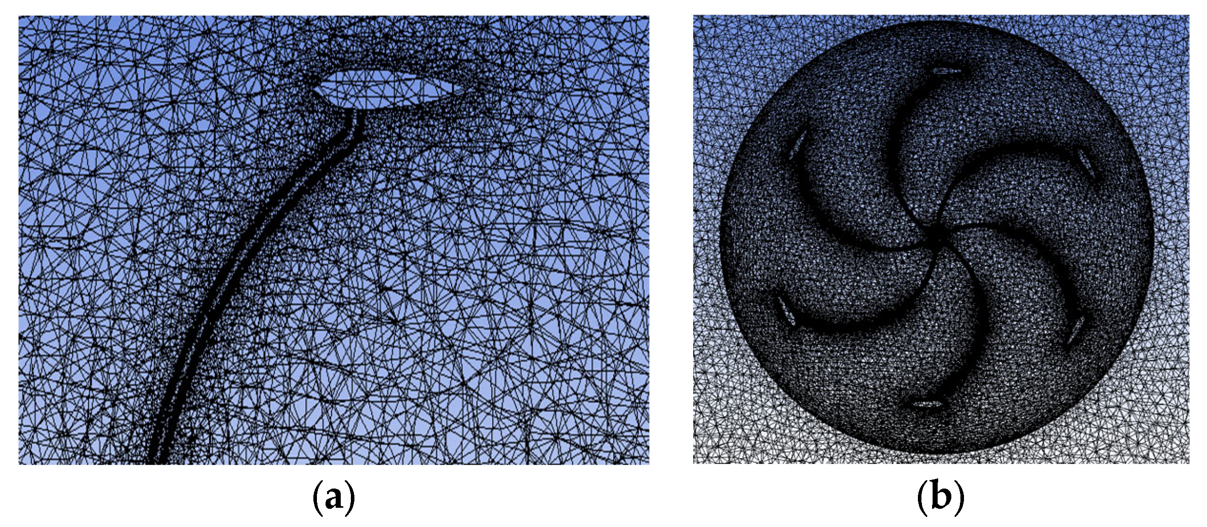
ANSYS 2021 R1 was used as the CFD software [26,27,28]. The solver in this software can solve complex geometric shapes (such as lift–drag composite blades) without a high cost [28].

3.1. Mesh

The use of tetrahedral unstructured grids for grid division allows for the grid refinement of key parts of the wind turbine blades, which can better simulate the real flow field environment in Fluent. To ensure the consistency of the simulation experiment and exclude the influence of irrelevant variables, the simulation validation parameters for different wind turbines in this article remained the same. Figure 4 shows the grid division of the lift–drag composite wind turbine, with a grid number of 6,976,741 and a node number of 1,249,544.

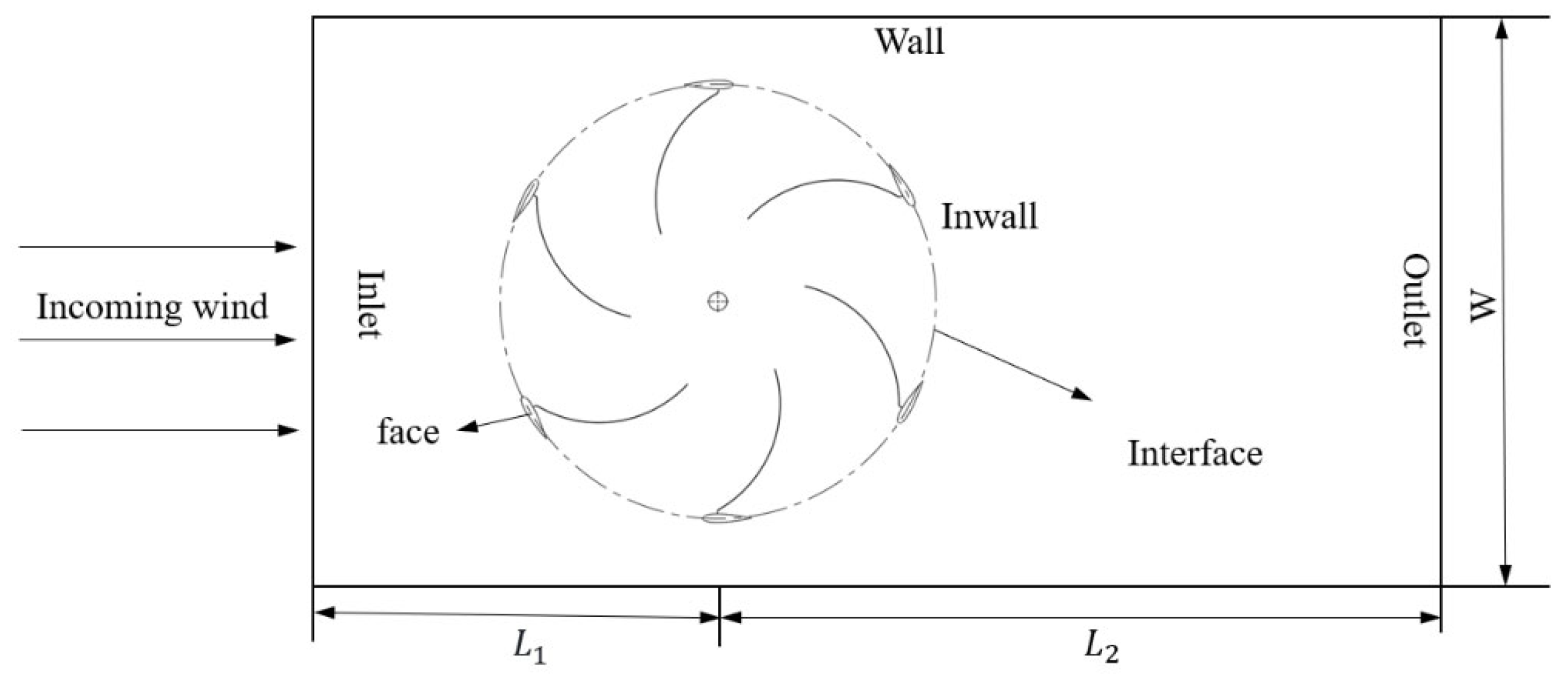
3.2. Boundary Conditions

In order to eliminate irrelevant variables and make the Fluent simulation model more reference, the calculation model was modeled exactly the same. For the convenience of calculation, the schematic diagram of the computational domain is shown in Figure 5. Because the calculation of the influence of the boundary conditions when the wind turbine rotates is not emphasized, the boundary conditions are determined to be L 1 = 600 mm, L 2 = 1800 mm, and W = 800 mm.

3.3. Turbulence Model

The k-epsilon model was selected for this simulation, with expandable walls selected. Combined with sliding-grid technology and second-order turbulent kinetic energy, a time-stepping solution method called Coupled was used. This method couples the solution processes of the solid domain and fluid domain to achieve information exchange and mutual influence between them. It can accurately describe the process of multiple physical phenomena. The calculation domain was set as the velocity inlet, the turbulence intensity was set to 5%, and the outlet was set as a free-flow outlet without considering the roughness, as the fluid velocity and pressure at the outlet are uncertain and are free-flow fields. The interface between the rotating domain and the stationary domain was set as the slip surface, and the slip mesh technique was used for the slip surface.

3.4. Simulation Parameters

With the other parameter conditions held constant, the wind speed was 5 m/s, and the air density and viscosity were set to 1.225 kg/m3 and 1.78105 kg/m/s, respectively. The rotational speed and torque of the vertical-axis wind turbine were calculated by setting the dynamic grid and 6 degrees of freedom. These attributes were applied as 6DOF UDF to the rotor boundary and rotating grid area in the “Dynamic Grid Area” dialog box. The time step was set to 0.02 s to improve the accuracy of the calculation, and the convergence criterion was determined to be 1 × 10 - 6 .

4. Results and Discussion

Before studying the aerodynamic performance of different drag-type blade curvatures and widths, the mesh density, boundary conditions, turbulence model, and simulation parameters have been illustrated above to ensure the independence of mesh size and parameter settings. The aerodynamic performance of different drag-type blades varies significantly in terms of curvature and width. In this section, the results obtained with Fluent are first used to analyze and compare the aerodynamic performance of fully drag-type wind turbines with different curvatures, explore the optimal curvature model for a certain structure of wind turbines, and lay the foundation for the design of drag-type blades of composite wind turbines.

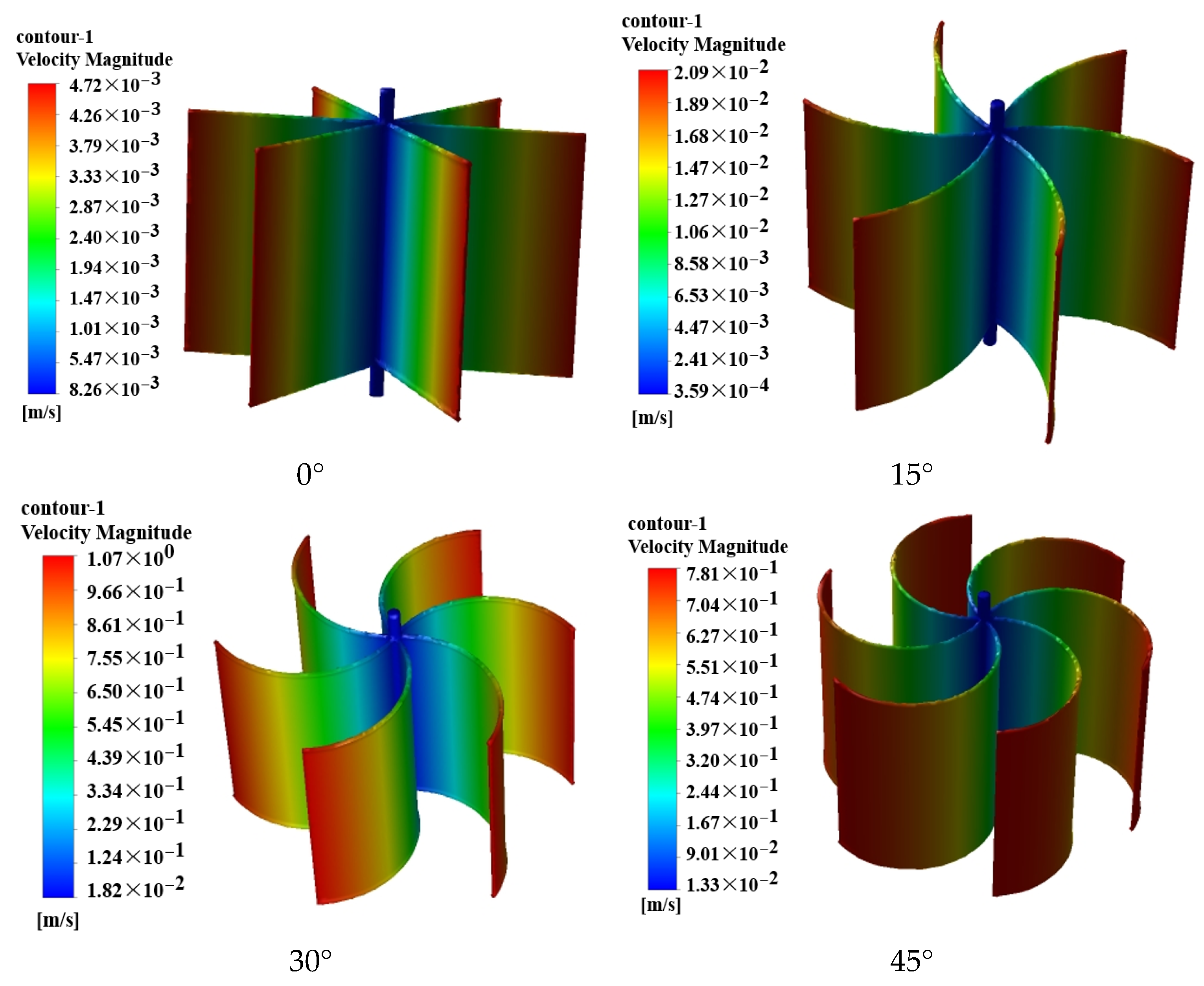
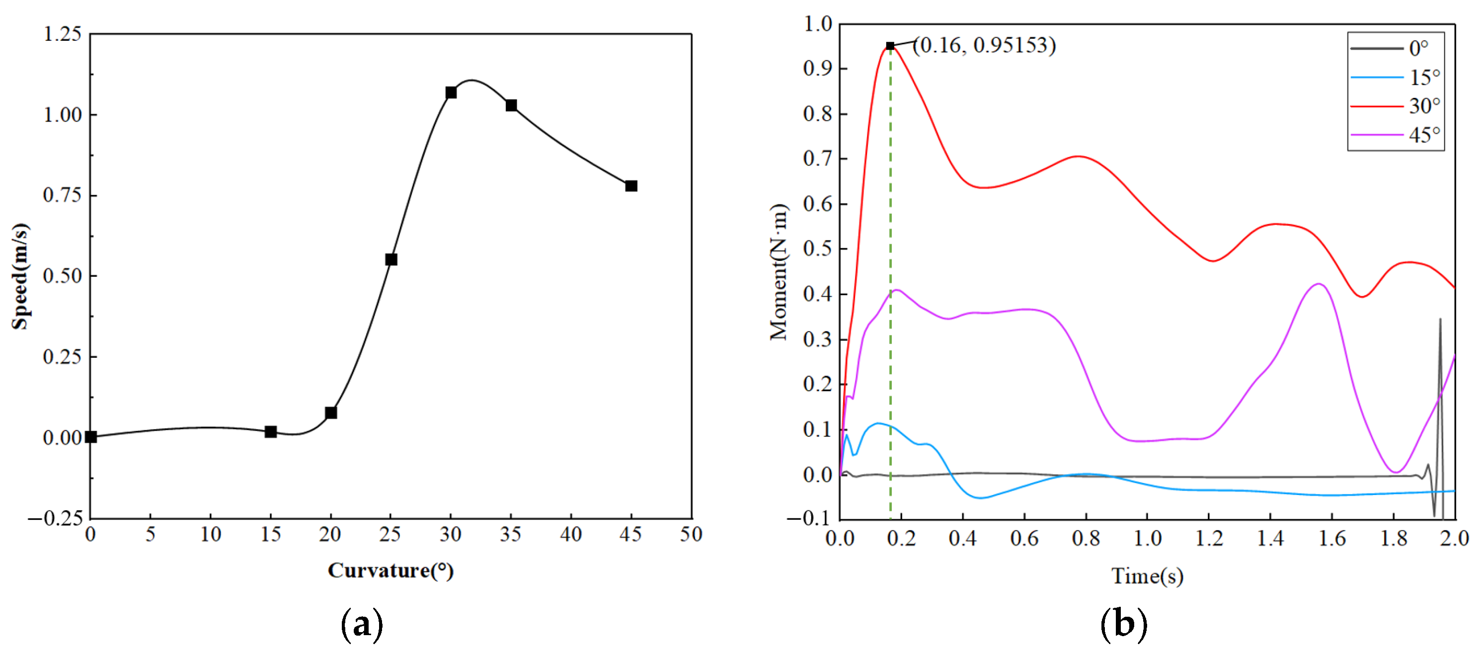
4.1. Exploration of Blade Curvature

The rotor solidity has a great influence on the wind energy utilization rate, and many scholars have studied it [29,30,31,32]. As shown in Equation (11), the rotor solidity σ is the numerical relationship between the chord length and the number of blades and the radius of the wind wheel.
σ = B C 2 R
where B and C , respectively, represent the number of blades and chord length of the wind wheel, and R represents the radius of the wind wheel. Many scholars have shown that when the wind wheel solidity is 0.25~0.45, the vertical-axis wind turbine shows better aerodynamic performance [33,34,35,36,37]. Since the wind wheel solidity is not the focus of this study, the solidity of the model in this paper is 0.35. Where H D = 0.8, the structural parameters are shown in Table 1. Simplified drawings of the wind turbine with different curvatures are shown in Figure 6; four values of curvature were used in this study, which are 0°, 15°, 30°, and 45°, with a theoretical maximum curvature of 45°.
Figure 7 shows the speed changes in fully drag-type wind turbines with different curvatures and the same parameter settings. Fluent was used to monitor the maximum speed and torque changes for the four curvatures, as shown in Figure 8. It can be seen that the maximum speed after acceleration for the same time within the range of 0°~20° curvatures approaches almost the same value without significant changes. When the curvature increases from around 20° to 30°, the velocity increases linearly and rapidly, as shown in Figure 8a. The velocity reaches its maximum at around 30° and decreases significantly from around 30° as the curvature continues to increase to 45°. From the perspective of speed changes, for design and assembly reasons, a curvature of 30° is defined as the optimal curvature.
By monitoring the torque changes, as shown in Figure 8b, it is evident that the initial starting torque increases the fastest during the entire operation period with a curvature of 30°, and after 0.16 s of acceleration, the maximum torque reaches 0.95153 N·m, which is the best aerodynamic performance. As shown by the red and purple lines in the figure, the oscillation amplitude of the torque change relative to 45° is significantly reduced when the curvature is 30°, and the aerodynamic performance change is the most stable.

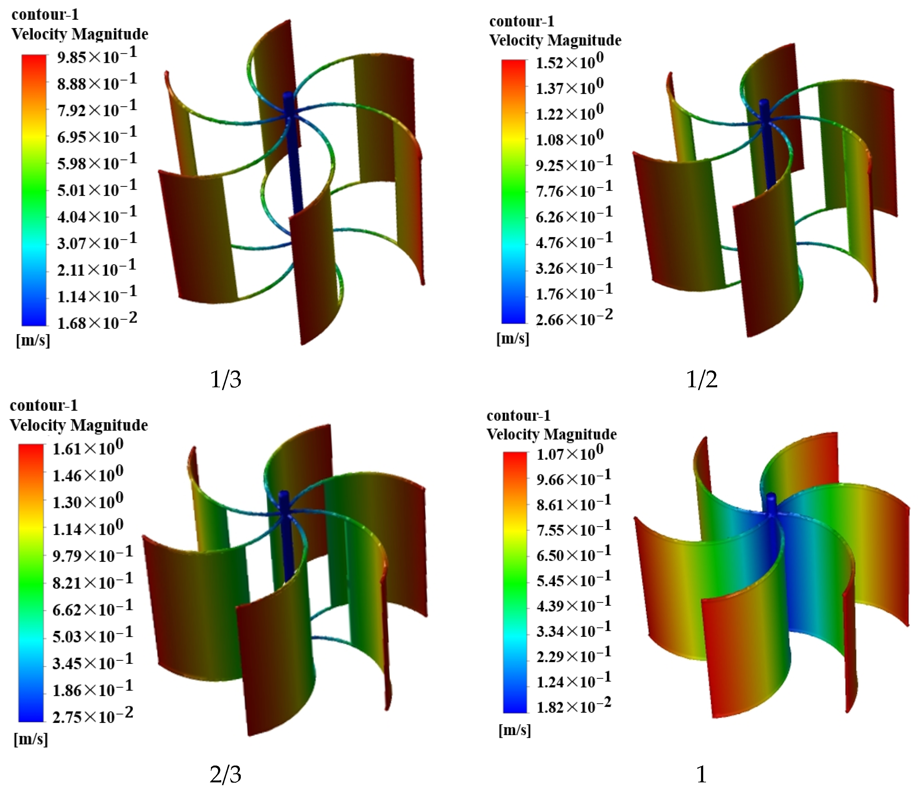
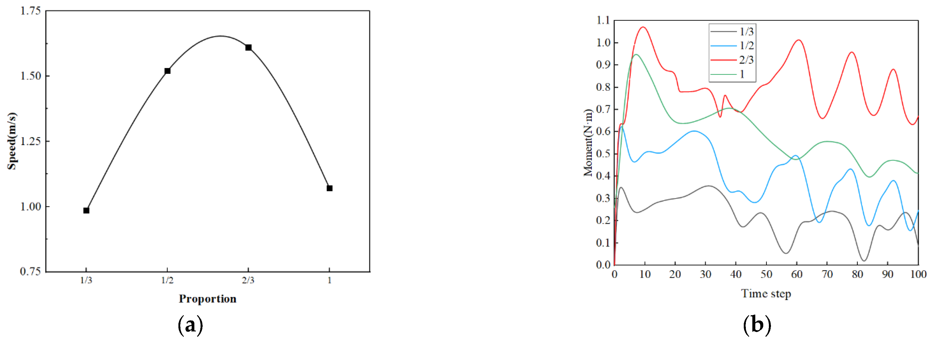
4.2. Exploration of Blade Width

Fluent was used to continue exploring the impact of the drag-type blade width on the aerodynamic performance of lift–drag composite wind turbines at an optimal curvature of 30°, as well as the performance of lift, drag, and lift–drag composite wind turbines before and after improvement, to determine the optimal lift–drag composite wind turbine model.
We compared the aerodynamic performance of drag-type blades with width ratios of 1/3, 1/2, and 2/3. The proportion of drag-type blades is represented by e , i.e.,
e = d R
The comparative analysis results of drag-type wind turbines with different blade widths with an optimal curvature of 30° are shown in Figure 9. Figure 10 shows the changes in maximum velocity and torque when Fluent monitors different blade widths. As the width ratio gradually increases from 1/3 to 1, the velocity first increases and then decreases. As the maximum speed value is closer to a width ratio of 2/3, in order to save calculation costs, we did not specifically explore it in this study. A width ratio of 2/3 is defined as the optimal blade width.
As shown in Figure 10b, the drag-type wind turbine with an optimal curvature of 30° has significantly greater torque than the fully enclosed drag-type blade when the blade width is 2/3, and it has better aerodynamic performance than other semi-enclosed drag-type blades. Here, the semi-enclosed blade is defined as a dual-blade drive, where the guide rail adaptive drag-type blade occupies two-thirds of the area between the main shaft and the lift-type blade, and the airflow can smoothly pass through the hollow part, forming the drag-type dual-drive blade.
In summary, the performance of the lift–drag composite wind turbine is the best when the curvature of the drag-type blade is 30° and the proportion of the blade width is 2/3. At the same time, the drag-type blade with a hollow design makes the air flow through the hollow part smoothly, forming the drag-type double-drive blade and greatly improving the self-starting ability.

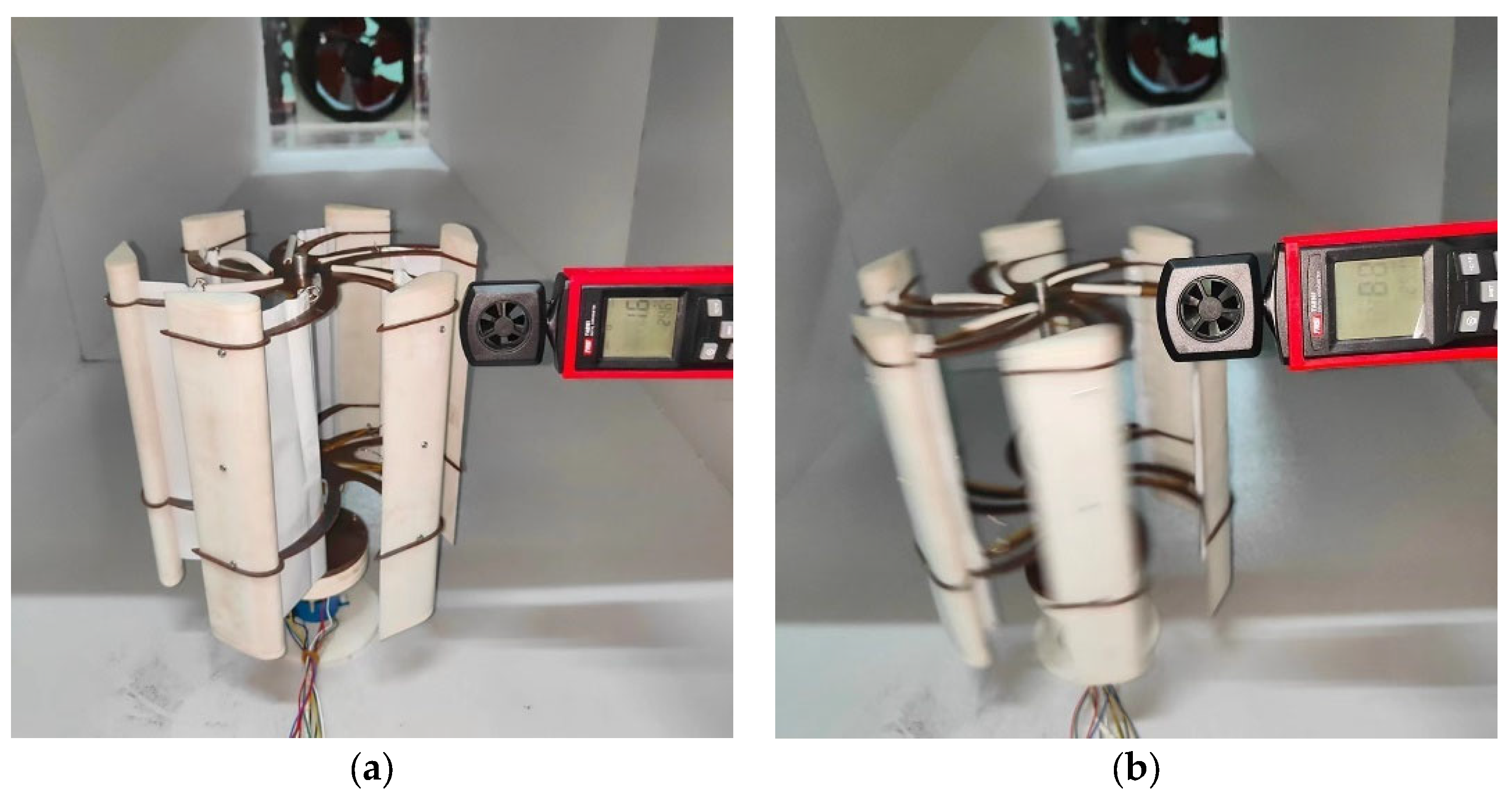
5. Experimental Details

In order to further explore the improvement degree of the self-starting performance of the composite wind turbine, the adaptive retracting and retracting of the guideway adaptive drag-type blade was analyzed, and a passive rotation experiment was carried out at wind speeds of 0–10 m/s. Figure 11 shows the wind tunnel model, and its basic parameters are shown in Table 2.
The wind turbine model described in this paper is equipped with a 50 W generator, and Table 3 shows the parameters of the generator.
As shown in Figure 12, the operation of the adaptive dual-drive lift–drag composite vertical-axis wind turbine was measured by using a wind speed meter, and the wind speed and the variation in the blade shrinkage and speed of the adaptive drag-type blade with the wind speed were obtained. The obtained experimental data are shown in Figure 13.
As shown in the figure above, the lift–drag composite vertical-axis wind turbine can start when the wind speed is 1.6 m/s, which is 23.8% lower than that of the lift-type wind turbine. When the wind speed reaches 8.8 m/s, the drag-type blade completely shrinks and completely transforms into a lift-type wind turbine. At this time, the wind turbine speed is 11.02 rad/s, and the spring is completely compressed. The C p of the adaptive double-drive lift–drag composite vertical-axis wind turbine was 5.98% higher than that of the ordinary lift-type wind turbine.
After that, the lift–drag composite wind turbine was compared with the lift–drag-type wind turbine and the drag-type wind turbine to verify the aerodynamic performance of the best curvature and the best width of the drag-type blade after the improvement. The starting characteristics of the three types of wind turbines before and after the improvement were monitored by Fluent dynamic grid technology, and the parameter settings were kept the same as in the above numerical simulation. The results are shown in Figure 14. As can be observed, the initial starting speed of the lift–drag composite wind turbine is 75.13% higher than that of the ordinary lift-type wind turbine.
As shown in Figure 15, the change law of wind energy utilization C p of the wind turbine with the tip speed ratio λ before and after the improvement was explored through numerical simulations and physical experiments. Since the simulation cannot accurately simulate the change process of the guide rail adaptive drag-type blades and the deformation of the spring, the lift–drag composite wind turbine was explored through physical tests.
As shown in Figure 15, the black numerical simulation curve and the red physical experimental curve tend to change in the same direction, but the red physical experimental curve has a slightly smaller value, which is due to the uneven wind speed at the physical experimental site, the hysteresis of data equipment, and friction between wind turbines. According to the analysis and calculations, the peak part of wind energy utilization C p is the place with the largest error, and the error rate between the physical experiment and simulation is 13.2%. Considering interference from other factors, the error is in a reasonable range.
In the above figure, the blue and black curves show the wind energy utilization C p of the drag-type and lift-type wind turbines, respectively. It can be seen that the wind energy utilization of the drag-type wind turbine reaches its peak at a lower tip speed ratio, λ = 1, and it can be started at a lower wind speed. However, the lift-type wind turbine can only be started at a high tip speed ratio, and C p reaches a peak at around λ = 3.5, but when λ < 1.5, C p is extremely low. At the same time, the drag-type blade compensates for the self-starting performance of the lift-type wind turbine at low wind speed. From the red curve in the figure, the lift-type wind turbine can make full use of the wind energy at low wind speed and has a wider applicable wind field. At the same time, when the wind speed reaches 8.8 m/s, the drag-type blade completely contracts and turns into a lift-type wind turbine.

6. Conclusions

The adaptive double-drive lift–drag composite vertical-axis wind turbine designed in this paper takes into account the curvature, width, and adaptive lift–drag transformation of the drag-type blade. And a design method for the double drive is proposed. The influence of different drag-type blade curvatures and widths on aerodynamic performance is analyzed, and the optimal curvature and blade width are obtained. Finally, numerical simulation and a physical experiment were carried out to verify the optimal structure of the lift–drag composite wind power turbine. The main conclusions of this paper are as follows:
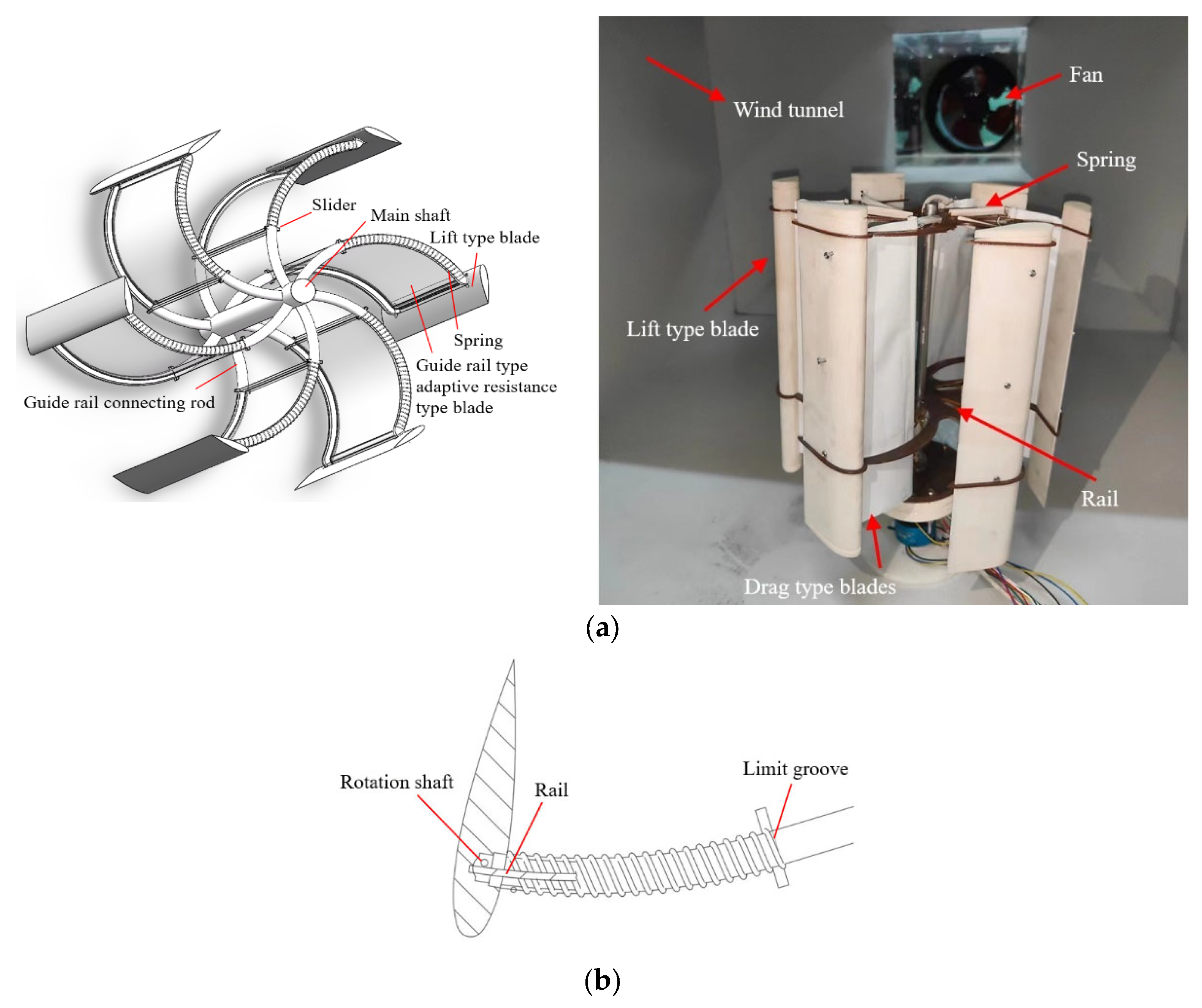
  • An adaptive double-drive lift–drag composite vertical-axis wind turbine is designed, which mainly includes lift-type and drag-type blades so that the vertical-axis wind turbine can make full use of wind energy, and a design method for the double drive is proposed. In this method, the guide rail adaptive drag-type blade occupies two-thirds of the area between the main axis and the lift-type blade, and the airflow can pass through the hollow part smoothly. It can effectively improve the self-starting ability. The theoretical equation of the lift–drag composite wind turbine is constructed, and the theoretical inference and the design of the adaptive system are completed.
  • The finite element model of the lift–drag composite wind turbine is established. The aerodynamic performance analysis of the lift–drag composite wind turbine in Fluent shows that the aerodynamic performance of the lift–drag composite wind turbine is the best when the curvature of the drag blade is 30° and the ratio of the blade width is 2/3.
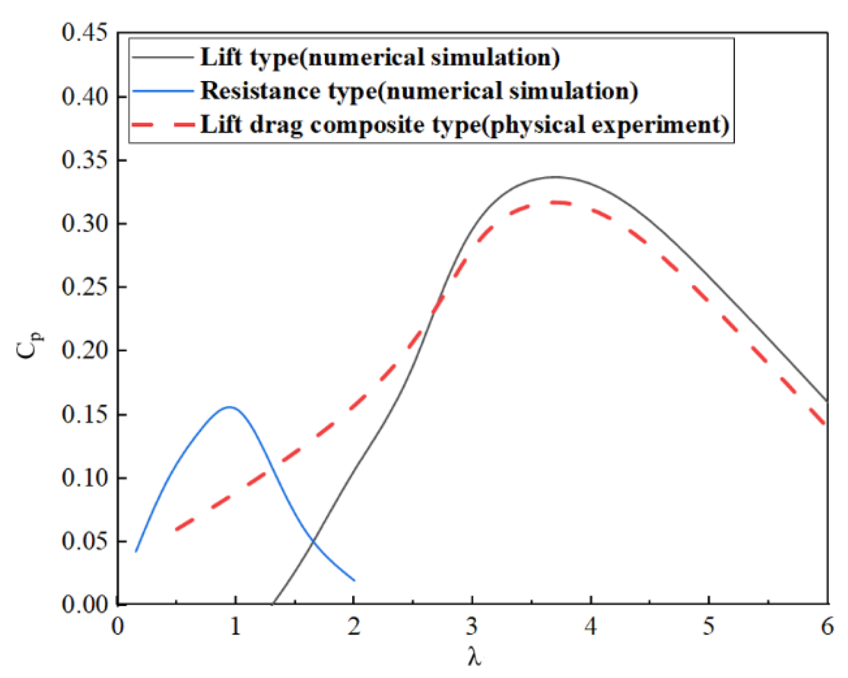
  • The simulation analysis and experimental test showed that the wind turbine can start when the incoming wind is 1.6 m/s, which is 23.8% lower than the existing lift-type wind turbine’s starting wind speed of 2.1 m/s. The comprehensive wind energy utilization of the adaptive double-drive lift–drag composite vertical-axis wind turbine was 5.98% higher than that of the ordinary lift-type wind turbine. At the same time, when the wind speed reaches 8.8 m/s, the drag-type blade completely shrinks and turns into a lift-type wind turbine, which can be applied to wind power generation in high-wind-speed wind farms.

Author Contributions

P.Y.: Conceptualization, Methodology, Validation, Formal Analysis, Investigation, Data Curation, Writing—Review and Editing, and Visualization. Y.L.: Conceptualization, Software, Data Curation, Writing—Original Draft, Writing—Review and Editing, and Visualization. Q.G.: Conceptualization, Formal Analysis, Writing—Review and Editing. S.L.: Investigation and Resources. Q.W.: Writing—Review and Editing. All authors have read and agreed to the published version of the manuscript.

Funding

This research was supported by the Opening Project of Shanxi Provincial Key Laboratory for Advanced Manufacturing Technology, grant number XJZZ202207, and the Fundamental Research Program of Shanxi Province, grant number 202203021222053.

Institutional Review Board Statement

Not applicable.

Informed Consent Statement

Not applicable.

Data Availability Statement

Data are contained within the article.

Conflicts of Interest

The authors declare no conflict of interest.

References

  1. Mahela, O.P.; Gupta, N.; Khosravy, M.; Patel, N. Comprehensive Overview of Low Voltage Ride Through Methods of Grid Integrated Wind Generator. IEEE Access 2019, 7, 99299–99326. [Google Scholar] [CrossRef]
  2. Valipour, M.; Singh, V.P. Global Experiences on Wastewater Irrigation: Challenges and Prospects. Balanc. Urban Dev. Options Strateg. Liveable Cities 2016, 72, 289–327. [Google Scholar] [CrossRef]
  3. Sharma, V.; Sharma, G. Recent development in the field of wind turbine. Mater. Today Proc. 2022, 64, 1512–1520. [Google Scholar] [CrossRef]
  4. Yuyi, Z.; Decai, Z.; Liang, L.; Wenbin, T.; Jun, L. The Design of Vertical Axis Wind Turbine Rotor for Antarctic. Inf. Technol. J. 2013, 12, 604–613. [Google Scholar] [CrossRef]
  5. Dhote, A.; Bankar, V. Design, analysis and fabrication of savonius vertical axis wind turbine. Int. Res. J. Eng. Technol. 2015, 2, 2048–2054. [Google Scholar]
  6. Salyers, T.E. Experimental and Numerical Investigation of Aerodynamic Performance for Vertical-Axis Wind Turbine Models with Various Blade Designs. Master’s Thesis, Georgia Southern University, Statesboro, GA, USA, 2016. [Google Scholar]
  7. Wang, B.; Geoffroy, S.; Bonhomme, M. Urban form study for wind potential development. Environ. Plan. B Urban Anal. City Sci. 2022, 49, 76–91. [Google Scholar] [CrossRef]
  8. Kumar, R.; Raahemifar, K.; Fung, A.S. A critical review of vertical axis wind turbines for urban applications. Renew. Sustain. Energy Rev. 2018, 89, 281–291. [Google Scholar] [CrossRef]
  9. Bedon, G.; Antonini, E.G.; De Betta, S.; Castelli, M.R.; Benini, E. Evaluation of the different aerodynamic databases for vertical axis wind turbine simulations(Review). Renew. Sustain. Energy Rev. 2014, 40, 386–399. [Google Scholar] [CrossRef]
  10. Thakur, N.; Biswas, A.; Kumar, Y.; Basumatary, M. CFD analysis of performance improvement of the Savonius water turbine by using an impinging jet duct design. Chin. J. Chem. Eng. 2019, 27, 794–801. [Google Scholar] [CrossRef]
  11. Al-Ghriybah, M.; Zulkafli, M.F.; Didane, D.H.; Mohd, S. Review of the recent power augmentation techniques for the savonius wind turbines. J. Adv. Res. Fluid Mech. Therm. Sci. 2019, 60, 71–84. [Google Scholar]
  12. El-Askary, W.A.; Nasef, M.H.; AbdEL-hamid, A.A.; Gad, H.E. Harvesting wind energy for improving performance of Savonius rotor. Wind Eng. Ind. Aerodyn. 2015, 139, 8–15. [Google Scholar] [CrossRef]
  13. Mosbahi, M.; Ayadi, A.; Chouaibi, Y.; Driss, Z.; Tucciarelli, T. Performance study of a Helical Savonius hydrokinetic turbine with a new deflector system design. Energy Convers. Manag. 2019, 194, 55–74. [Google Scholar] [CrossRef]
  14. Bhayo, B.A.; Al-Kayiem, H.H. Experimental characterization and comparison of performance parameters of S-rotors for standalone wind power system. Energy 2017, 138, 752–763. [Google Scholar] [CrossRef]
  15. Gharaati, M.; Xiao, S.; Wei, N.J.; Martínez-Tossas, L.A.; Dabiri, J.O.; Yang, D. Large Eddy Simulation of Helical- and Straight-Bladed Vertical Axis Wind Turbines in Boundary Layer Turbulence. J. Renew. Sustain. Energy 2022, 14, 053301. [Google Scholar] [CrossRef]
  16. Zamani, M.; Nazari, S.; Moshizi, S.A.; Maghrebi, M.J. Three dimensional simulation of J-shaped Darrieus vertical axis wind turbine. Energy 2016, 116, 1243–1255. [Google Scholar] [CrossRef]
  17. Mahdi, Z.; Mohammad Javad, M.; Seyed Rasoul, V. Starting torque improvement using J-shaped straight-bladed Darrieus vertical axis wind turbine by means of numerical simulation. Renew. Energy 2016, 95, 109–126. [Google Scholar] [CrossRef]
  18. Wang, Y.; Sun, X.; Dong, X.; Zhu, B.; Huang, D.; Zheng, Z. Numerical investigation on aerodynamic performance of a novel vertical axis wind turbine with adaptive blades. Energy Convers. Manag. 2016, 108, 275–286. [Google Scholar] [CrossRef]
  19. Chen, J.; Yang, H.; Yang, M.; Xu, H. The effect of the opening ratio and location on the performance of a novel vertical axis Darrieus turbine. Energy 2015, 89, 819–834. [Google Scholar] [CrossRef]
  20. Sengupta, A.R.; Biswas, A.; Gupta, R. Comparison of low wind speed aerodynamics of unsymmetrical blade H-Darrieus rotors-blade camber and curvature signatures for performance improvement. Renew. Energy Int. J. 2019, 139, 1412–1427. [Google Scholar] [CrossRef]
  21. Sun, X.; Chen, Y.; Cao, Y.; Wu, G.; Zheng, Z.; Huang, D. Research on the aerodynamic characteristics of a lift drag hybrid vertical axis wind turbine. Adv. Mech. Eng. (Sage Publ. Inc.) 2016, 8, 1. [Google Scholar] [CrossRef]
  22. Hosseini, A.; Goudarzi, N. Design and CFD study of a hybrid vertical-axis wind turbine by employing a combined Bach-type and H-Darrieus rotor systems. Energy Convers. Manag. 2019, 189, 49–59. [Google Scholar] [CrossRef]
  23. Feng, F.; Tong, G.; Ma, Y.; Li, Y. Numerical Simulation and Wind Tunnel Investigation on Static Characteristics of VAWT Rotor Starter with Lift-Drag Combined Structure. Energies 2021, 14, 6167. [Google Scholar] [CrossRef]
  24. Islam, M.; Ting, D.S.-K.; Fartaj, A. Aerodynamic models for Darrieus-type straight-bladed vertical axis wind turbines. Renew. Sustain. Energy Rev. 2008, 12, 1087–1109. [Google Scholar] [CrossRef]
  25. Aihara, A.; Mendoza, V.; Goude, A.; Bernhoff, H. A numerical study of strut and tower influence on the performance of vertical axis wind turbines using computational fluid dynamics simulation. Wind Energy 2022, 25, 897–913. [Google Scholar] [CrossRef]
  26. Ge, M.; Ke, W.; Chen, H. Pitch control strategy before the rated power for variable speed wind turbines at high altitudes. J. Hydrodyn. 2019, 31, 379–388. [Google Scholar] [CrossRef]
  27. Ma, Y.; Zhu, Y.; Zhang, A.; Hu, C.; Liu, S.; Li, Z. Hydrodynamic performance of vertical axis hydrokinetic turbine based on Taguchi method. Renewable Energy 2022, 186, 573–584. [Google Scholar] [CrossRef]
  28. Celik, Y.; Ingham, D.; Ma, L.; Pourkashanian, M. Design and aerodynamic performance analyses of the self-starting H-type VAWT having J-shaped aerofoils considering various design parameters using CFD. Energy 2022, 251, 123881. [Google Scholar] [CrossRef]
  29. Tian, W.; Mao, Z.; Zhang, B.; Li, Y. Shape optimization of a Savonius wind rotor with different convex and concave sides. Renew. Energy: Int. J. 2018, 117, 287–299. [Google Scholar] [CrossRef]
  30. Pope, K.; Naterer, G.F.; Dincer, I.; Tsang, E. Power correlation for vertical axis wind turbines with varying geometries. Int. J. Energy Res. 2011, 35, 423–435. [Google Scholar] [CrossRef]
  31. Xu, Y.L.; Peng, Y.X.; Zhan, S. Optimal blade pitch function and control device for high-solidity straight-bladed vertical axis wind turbines. Appl. Energy 2019, 242, 1613–1625. [Google Scholar] [CrossRef]
  32. Zhu, H.T.; Hao, W.X.; Li, C.; Ding, Q.W. Numerical study of effect of solidity on vertical axis wind turbine with Gurney flap. J. Wind Eng. Ind. Aerodyn. 2019, 186, 17–31. [Google Scholar] [CrossRef]
  33. Sagharichi, A.; Zamani, M.; Ghasemi, A. Effect of solidity on the performance of variable_pitch vertical axis wind turbine. Energy 2018, 161, 753–775. [Google Scholar] [CrossRef]
  34. Xiang, B.; Miao, W.; Li, C.; Ni, L. Effect of Blade Solidity on Wind Field Aerodynamic Characteristics in Vertical Axis Wind Turbine Group. Therm. Power Eng. 2020, 11, 135–142. [Google Scholar] [CrossRef]
  35. Qu, J.; Liu, R.; Qu, P.; Yin, W.; Zhao, Y. Effects of combination of blade number and chord length on performance of vertical axis wind turbine. Renew. Energy 2017, 5, 734–739. [Google Scholar] [CrossRef]
  36. Li, Y.; Tong, G.; Qu, C.; Feng, F. Numerical simulation of aerodynamic characteristics of straight-bladed vertical axis wind turbine with large solidities. J. Drain. Irrig. Mach. Eng. 2022, 7, 701–706. [Google Scholar]
  37. Chen, Y.; Fu, X.; Zhang, J.; Star, O.; Wu, C.; Zhao, R. Effect of Solidity on the Performance of a Vertical Axis Wind Turbine byNumerical Simulation Analysis. New Energy Prog. 2017, 6, 409–416. [Google Scholar] [CrossRef]
Figure 1. Lift–drag composite vertical-axis wind turbine model. (a) Theoretical model. (b) Physical model.
Energies 16 07529 g001
Figure 2. Two-dimensional projection of composite wind turbine.
Energies 16 07529 g002
Figure 3. Single-blade model of composite wind turbine.
Energies 16 07529 g003
Figure 4. Grid division conditions. (a) Single-blade mesh division. (b) Overall grid division.
Energies 16 07529 g004
Figure 5. Definition of boundary conditions.
Energies 16 07529 g005
Figure 6. Drag-type blade curvature model.
Energies 16 07529 g006
Figure 7. Aerodynamic performance of different curvatures.
Energies 16 07529 g007
Figure 8. Comparison and analysis of aerodynamic performance with different curvature degrees. (a) The variation in speed with curvature. (b) The variation in torque with curvature.
Energies 16 07529 g008
Figure 9. Aerodynamic performance of different blade widths.
Energies 16 07529 g009
Figure 10. Comparative analysis of aerodynamic performance of different blade widths. (a) The variation in speed with blade proportion. (b) The variation in starting torque with blade proportion.
Energies 16 07529 g010
Figure 11. Wind tunnel experimental setup.
Energies 16 07529 g011
Figure 12. Operation of composite wind turbine. (a) Starting wind speed. (b) Complete contraction wind speed.
Energies 16 07529 g012
Figure 13. Changes in shrinkage and speed of drag-type blades with wind speed.
Energies 16 07529 g013
Figure 14. Starting characteristics of wind turbines before and after improvement.
Energies 16 07529 g014
Figure 15. Wind energy utilization changes with tip speed ratio before and after improvement.
Energies 16 07529 g015
Table 1. Model parameters.
ParameterNumerical Value
Chord length c/mm40
Radius R/mm340
Height H/mm580
Number of blades/pieces6
Curvature parameter/°0°, 15°, 30°, 45°
Table 2. Wind tunnel parameters.
NameDiameterLengthSquare-Mouth Edge Length
Soft connection420350-
Round to square-400350
Test section-600350
Gradual expansion sectionSmall end-500350
Big end900
Settling chamber-900900
Table 3. Specific parameters of wind turbines with combined lift and drag.
NameParameterNameParameter
Generator modelNE-50 WSRated voltage/V12
Rated power/W50Rated speed/rpm750
Starting torque/N·m>0.15Weight/kg1.5
Working temperature rise/°C<70Insulation levelH
Disclaimer/Publisher’s Note: The statements, opinions and data contained in all publications are solely those of the individual author(s) and contributor(s) and not of MDPI and/or the editor(s). MDPI and/or the editor(s) disclaim responsibility for any injury to people or property resulting from any ideas, methods, instructions or products referred to in the content.

