Abstract
With the growing utilization of disc motors, the enhancement of their operational stability has become a critical research area. The existing studies usually focus on improving the pole structure of the rotor or the stator structure to optimize one performance of the motor and less on optimizing multiple performances. This paper simultaneously improves the rotor pole structure and stator tooth structure of the motor in order to optimize the sinusoidal waveform of the no-load back electromotive force and the cogging torque at the same time to achieve the goal of reducing the vibration and noise of the permanent-magnet synchronous dual-rotor statorless magnetically coupled disc motor and improve its operational stability. A finite element simulation model of a 20-pole, 24-slot permanent-magnet synchronous dual-rotor statorless magnetically coupled disc motor is established to analyze the influence of various factors, including the number of magnetic pole steps, the opening position, depth, and width of the stator auxiliary slot, on the motor performance. The results show that this stator–rotor combination improvement method effectively reduces the total harmonic distortion (THD) and attenuates multiple harmonics, and the peak cogging torque pulsation is significantly improved while other properties of the motor meet the technical requirements, and the motor performance is improved.
1. Introduction
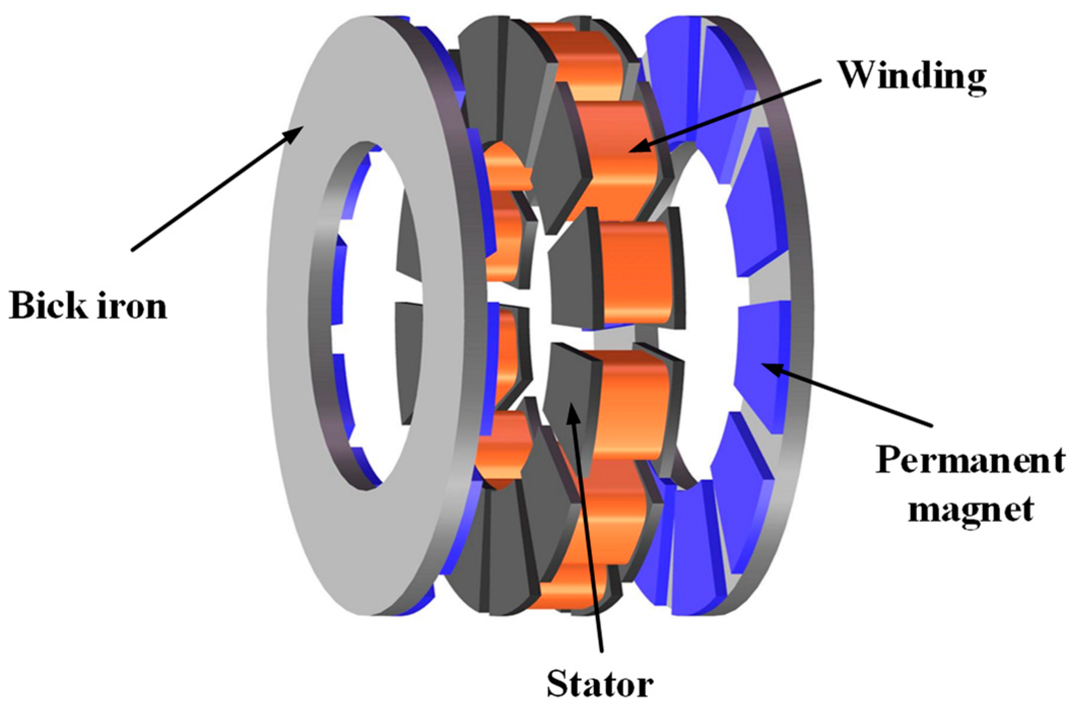
Due to their high efficiency, high torque density, small size, and good reliability, permanent-magnet motors are being increasingly utilized in practical engineering. They can be categorized into two main types: axial-flux permanent-magnet motors and radial-flux permanent-magnet motors, with the latter being more common and maturely developed. Therefore, in recent years, research by both domestic and foreign scholars has been increasingly focused on the development of new topology motors, specifically axial-flux motors [1]. The disc-shaped permanent-magnet synchronous double-rotor stator without a magnetic yoke motor is an axial composite motor structure whose topology is illustrated in Figure 1. In comparison with traditional radial motors, the double-outer-rotor single-stator structure offers a compact axial structure, high efficiency, and high power density. The stator design without a magnetic yoke not only reduces the weight of the motor but also results in a small starting torque. As a result, it is being increasingly employed in wind power generation, new energy vehicles, and other fields.

Figure 1.
Structural diagram of double-rotor stator yokeless disc motor.
With increasing attention, higher demands are being placed on performance improvement in axial-flux motors by various industries. The sinusoidality of the no-load back electromotive force waveform of synchronous generators is strictly required in industrial production. Therefore, reducing the harmonic components of the no-load back electromotive force has become an important goal. The sinusoidality of the no-load back electromotive force waveform was improved by Y. Li et al. [2] through the optimization of the number of magnetic poles, size, and magnet thickness of the permanent-magnet synchronous motor. The influence of the rotor pole arc on the no-load back electromotive force waveform was evaluated by W. Hua et al. [3], indicating that there exists an optimal rotor pole arc for the minimum harmonic content of the no-load back electromotive force waveform. M. Shokri et al. [4] showed that changing the pole structure can optimize the no-load back electromotive force waveform by comparing the no-load back electromotive force waveform of sinusoidal-shaped, cylindrical-shaped, and normal sector-shaped poles. J. Liu et al. [5] investigated the attenuation of the harmonic content of no-load reverse electromotive force by rotor slanted poles and segmented slanted poles. J. Wu et al. [6,7,8] investigated an eccentric design of the permanent magnets in order to improve the aberration of the no-load back electromotive force waveform rate. Y. Liu et al. [9] designed orthogonal experiments using the Taguchi method to optimize the performance of a dual-rotor flux-switching motor, reducing the higher harmonic content of the no-load back electromotive force and improving its sinusoidality. The performance of the motor was improved by Bo Cheng et al. [10] by combining Halbach-array permanent magnets with soft magnetic composite stator cores using a nonlinear optimization algorithm to solve multi-objective optimization problems. X. Zhang et al. [11] changed the shape of each magnet from rectangular to trapezoidal based on the traditional Halbach-array permanent-magnet synchronous motor, optimizing the air-gap flux density and reducing the distortion rate of the no-load back electromotive force. In the above studies, by changing the number of rotor poles, the size, or the pole arc coefficient, using skewed poles or segmented poles, etc., researchers aimed at optimizing the no-load back electromotive force waveform and did not take the motor cogging torque as the main target performance improvement. However, the cogging torque is also one of the important indexes affecting the stable operation of the motor.
The cogging torque is generated by the magnetic flux variation between the rotor and stator slots during synchronous motor operation. The existence of cogging torque can cause torque ripple, vibration noise, and other issues, which can reduce the reliability and stability of motor operation. Some research and analysis have been conducted by scholars at home and abroad to suppress cogging torque. The influence of a stepped skewed stator yoke on the cogging torque of a transverse flux motor was studied by Taravat S. et al. [12]. The cogging torque was weakened by C. Ma et al. [13] through the combination of magnetic pole segmentation with rotor open auxiliary slots. Effective reduction in the cogging torque and obtaining a more sinusoidal no-load back electromotive force waveform were achieved by Güleç M. et al. [14] by using inclined poles and rotor pole displacement, making the motor operate more stably at low speeds. M. Aydin et al. [15] proposed a new coreless spoke-type sinusoidal rotor segmented permanent-magnet synchronous motor, which achieved higher performance and torque compared to traditional AFPM motors. The reasonable selection of auxiliary slot numbers to weaken the cogging force was verified through theoretical derivation and experimental research by K. Huang et al. [16]. L. Xu et al. [17] optimized an axial-flux motor by optimizing parameter combinations and using a genetic algorithm to optimize the pole arc coefficient, stator width coefficient, slot displacement, and inclined poles, resulting in a significant reduction in cogging torque and an improvement in the sinusoidality of the no-load back electromotive force waveform. The cogging torque suppression mechanism of different-shaped segmented magnetic pole strategies was revealed using the finite element method by L. Xiao et al. [18], and the motor’s cogging torque was optimized by controlling parameters using the rectangular magnetic pole segmentation strategy. B. Zhao et al. [19] proposed a novel winding topology to reduce the cogging torque of a five-phase fractional slot concentrated winding motor. K. Sun et al. [20] proposed a method to optimize the torque performance of IPMSM using single-layer FSCW to obtain the optimal solution and reduce the torque pulsation using the SOA algorithm. The above studies have made progress in optimizing the cogging torque of the motor in terms of stator yoke tilt, addition of auxiliary slots, rotor inclined poles, and optimization of motor parameters by combining algorithms, where structural improvement in rotor poles has been widely studied in disk motors, but less research has been carried out on the change in stator structure.
Although many studies have been conducted on performance improvement in disk motors, most of them still choose a single performance parameter as the optimization objective. This paper proposes a combined optimization method based on stator opening auxiliary slots with stepped magnets to achieve the goal of simultaneous optimization of the no-load back electromotive force waveform and the cogging torque of the disk generator to improve the stability of the motor during operation. A 20-pole, 24-slot permanent-magnet synchronous dual-rotor stator yokeless disk motor model is established to improve the overall performance of the motor by comparing the influence of different orders of magnetic poles on the distortion rate () of the no-load back EMF waveform, that is, whether the no-load back EMF waveform is closer to the sinusoidal type; and the effects of different slot widths, depths, and slotting positions of auxiliary slots of the stator on the cogging torque, so as to select optimal parameters and improve the overall performance of the motor.
2. Methods
2.1. No-Load Back EMF Waveform Characteristics
It has been shown that the magnetic pole structure can be effectively optimized to improve the waveform of the no-load back electromotive force during no-load operation [2]. Designing the permanent magnet as a sinusoidal shape can make the waveform of the no-load back electromotive force closer to a sinusoidal wave, weaken the harmonic content of the back electromotive force during no-load operation, and obtain a larger air-gap flux density. However, designing the surface-mounted permanent magnet to a shape close to sinusoidal in actual manufacturing processes is complex and incurs a significant amount of cost. Therefore, this paper chooses to change the rectangular permanent magnet to a stepped magnetic pole, which satisfies the structural change close to sinusoidal and is easy to manufacture without causing a significant increase in motor cost. The evaluation index for the sinusoidality of the no-load back electromotive force waveform is the total harmonic distortion () [21], defined as the percentage of the root-mean-square value of the harmonic components (after removing the fundamental component) to the root-mean-square value of the fundamental component, expressed as
where represents the fundamental component of the no-load back electromotive force, and represents the odd-order harmonic components of the no-load back electromotive force.
A smaller indicates that there are fewer harmonic components in the no-load back electromotive force, which means that the waveform is closer to a sinusoidal shape and the motor has lower losses.
2.2. Cogging Torque Characteristics
The cogging torque of a permanent-magnet motor is defined as the negative derivative of the magnetic field energy inside the motor with respect to the position angle when the motor is not energized [22], expressed as
where refers to the relative position angle between the rotors, which is the angle between the centerline of a stator tooth and the centerline of the corresponding magnetic pole. The magnetic field energy inside the motor can be approximated as the sum of the magnetic field energy in the motor air gap and the permanent magnet, expressed as
where represents the distribution function of air-gap magnetic flux density, represents the magnetic permeability of the air gap, and represents the mechanical angle of rotation of the motor.
The distribution function of air-gap magnetic flux density is expressed by the remanent magnetization induction and relative magnetic conductivity function of the permanent magnet, expressed as
after conducting a Fourier decomposition of and , expressed as
where represents the number of pole pairs in the rotor; represents the remanent magnetization of the permanent magnet; ; and , where is the pole arc coefficient of the permanent magnet.
where represents the number of stator slots, and represents the Fourier coefficient of the magnetic conductivity function.
By substituting Equations (4)–(6) into Equation (2), we obtain the expression for the cogging torque, expressed as
where represents the outer radius of the armature, represents the inner radius of the stator yoke, represents the axial length of the armature core, and .
There is not much difference between the axial-flux permanent-magnet motor and the conventional radial motor, except that the air gap of the radial motor is a hollow cylinder, while that of the axial-flux motor is a ring. The integration method for storing energy in the air gap is slightly different for the two motors [23]. Therefore, the cogging torque in an axial-flux permanent-magnet motor is given by the following equation, expressed as
where is the average diameter of the motor, is the effective length of the armature, and is the effective air-gap length of the motor.
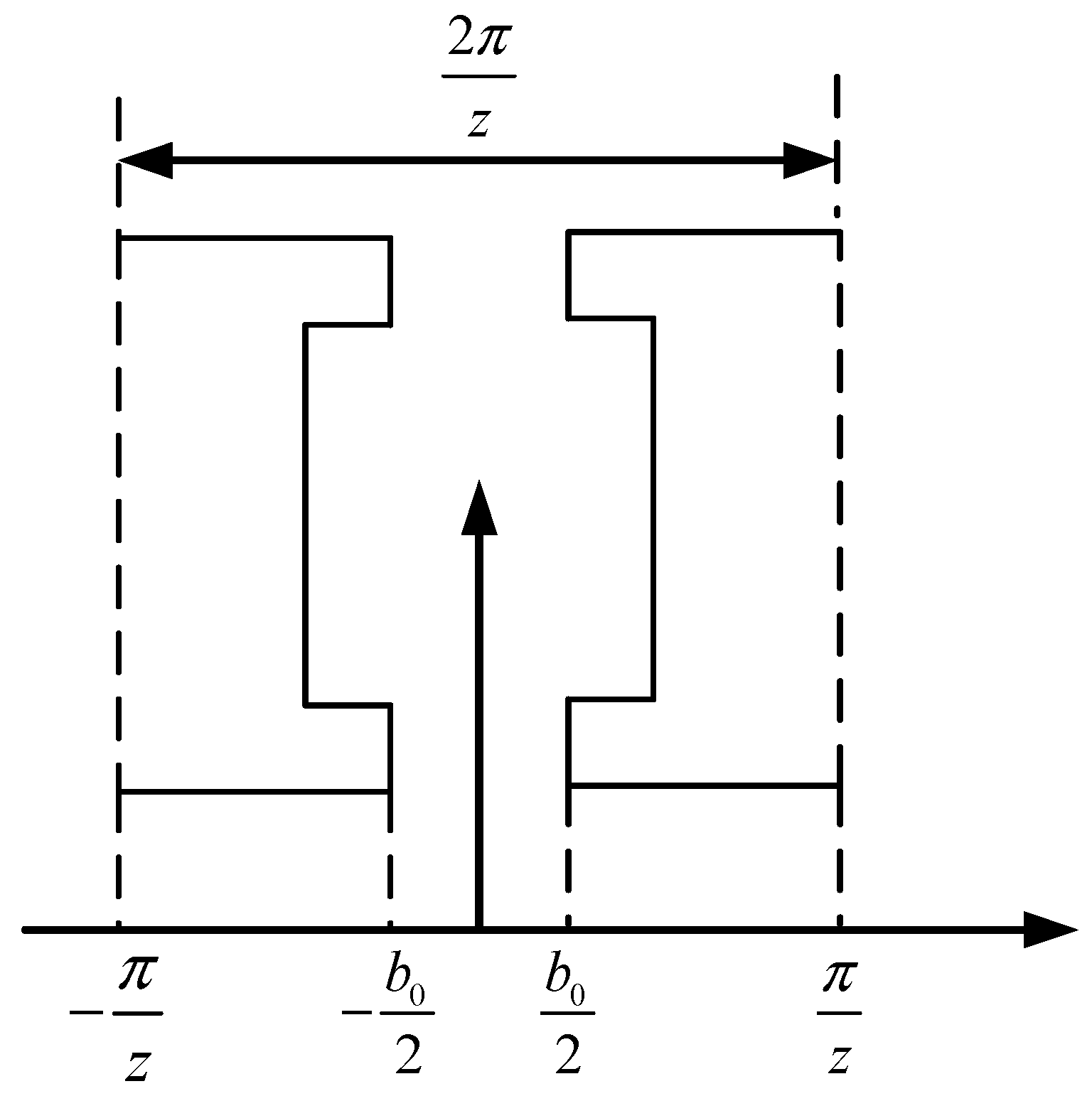
From Formula (8), it can be seen that is a basic design parameter of the motor. To reduce the cogging torque without changing the basic parameters of the motor, it is effective to reduce B, which is the Fourier decomposition coefficients of the air-gap magnetic density squared for permanent magnets, and G, which is the Fourier decomposition coefficients of the relative air-gap permeability squared. According to the simplified stator slot structure model shown in Figure 2, the Fourier coefficients of the magnetic conductivity function can be idealized, expressed as

Figure 2.
Model diagram of stator tooth-slot structure.
It can be seen that the stator open auxiliary slots will have an impact on the calculation of the derivative interval and change the magnitude of , thereby affecting the cogging torque. Therefore, this paper proposes to optimize the cogging torque by using stator open auxiliary slots. However, since the above analytical derivation ignores factors such as core saturation, only the cogging torque of the motor is analyzed qualitatively; the current in the armature windings is set to zero at a constant rotational speed, which is used to simulate an open-circuit winding and a finite element analysis is performed to observe the change in the cogging torque.
3. Results and Discussion
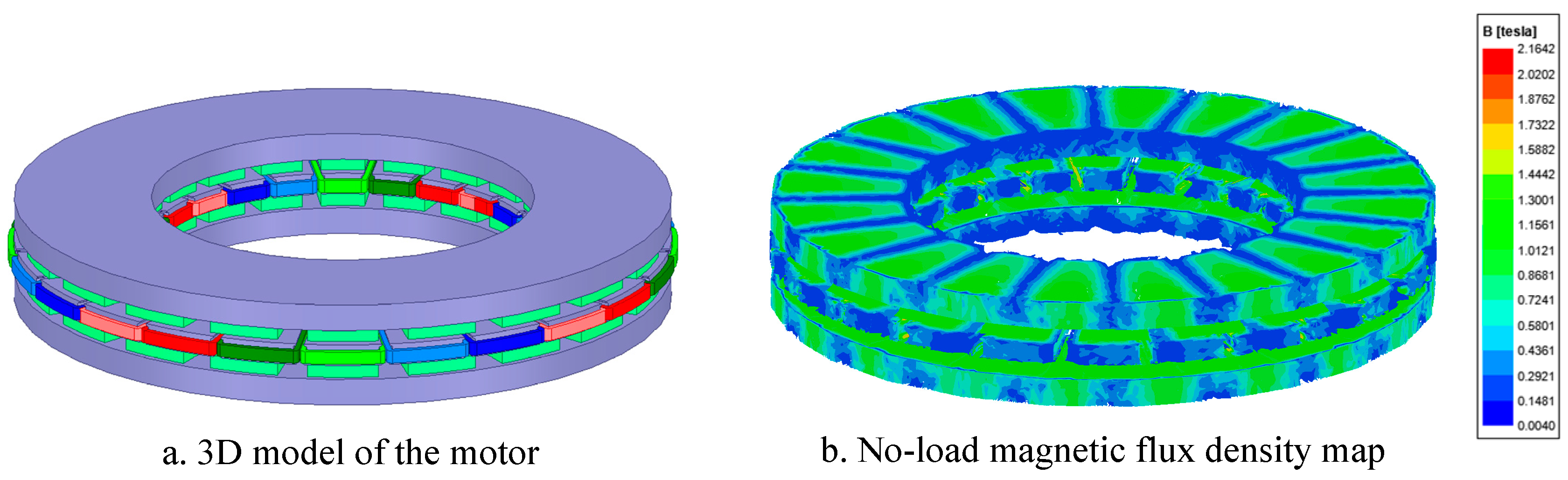
In this paper, a 20-pole, 24-slot axial-flux permanent-magnet synchronous double-rotor stator without a yoke motor is used as an example. A 3D finite element model is established using Ansoft Maxwell 2021 software, as shown in Figure 3a,b, which show the magnetic density cloud diagram of the motor at no load. Neglecting the tooth edge agglomeration effect, the average tooth magnetic density of this motor is around 1.6 T, which meets the initial design criteria. The main technical specifications and parameters are shown in Table 1. To reduce the computational load and take full account of the symmetry and periodicity of the motor structure, a quarter model of the motor is selected for analysis.
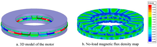
Figure 3.
Three-dimensional finite element model diagrams of motor.

Table 1.
The main parameters of the motor.
3.1. No-Load Back EMF Waveform Optimization
Taking a single permanent-magnet pole as an example, assuming that the heights of each order of pole differ by 1 mm, the pole arc coefficient is used in conjunction with the center axis of the pole to evenly distribute the pole angle for each order. That is, when the number of pole steps is and the pole arc coefficient is , the pole angle occupied by the first-order pole is , and we have . The i = 1, 2, and main optimized structural parameters for the pole are shown in Figure 4.
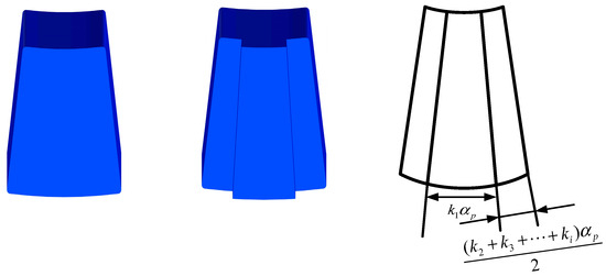
Figure 4.
Parameter diagram of ladder magnetic pole structure.
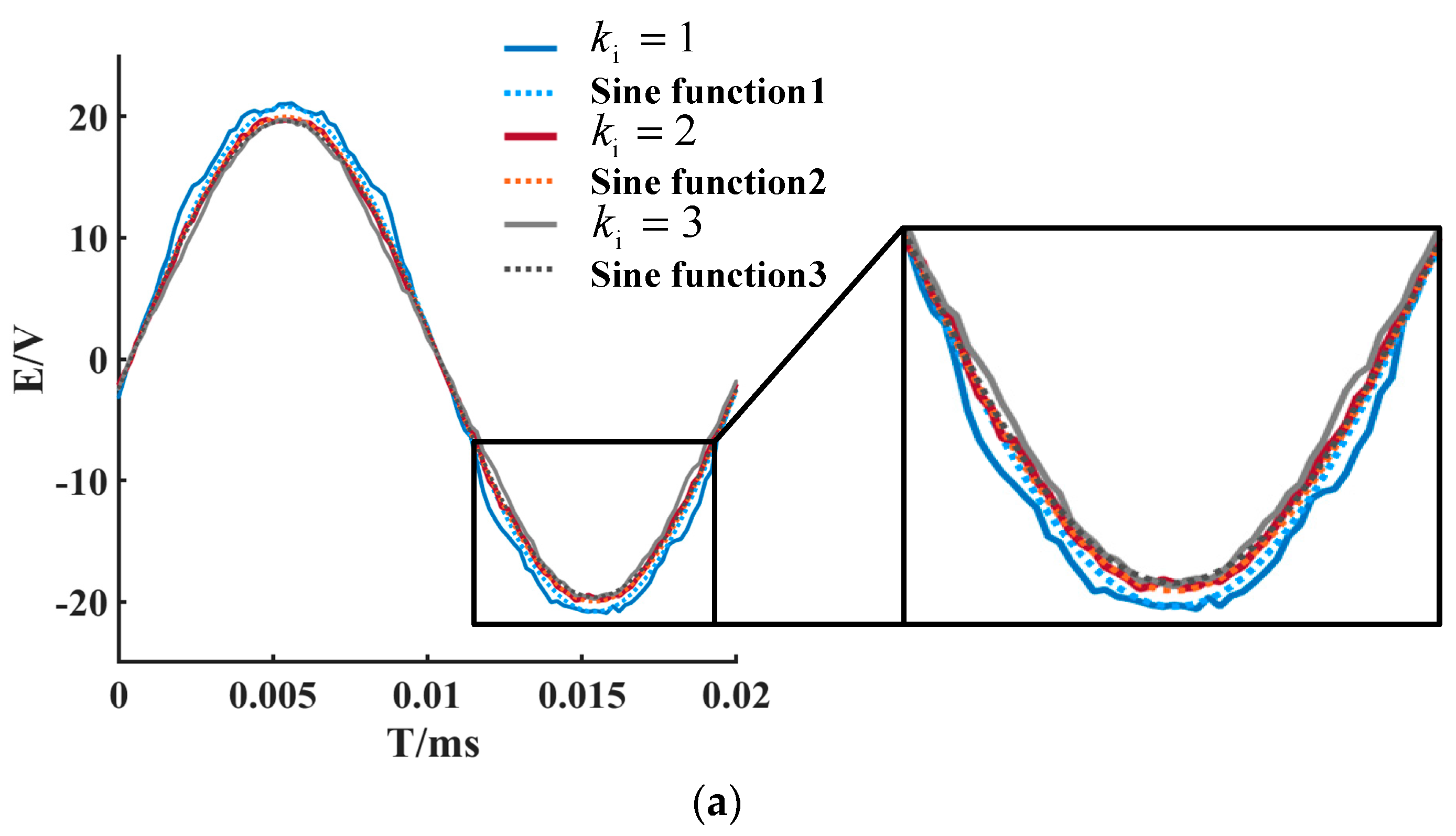
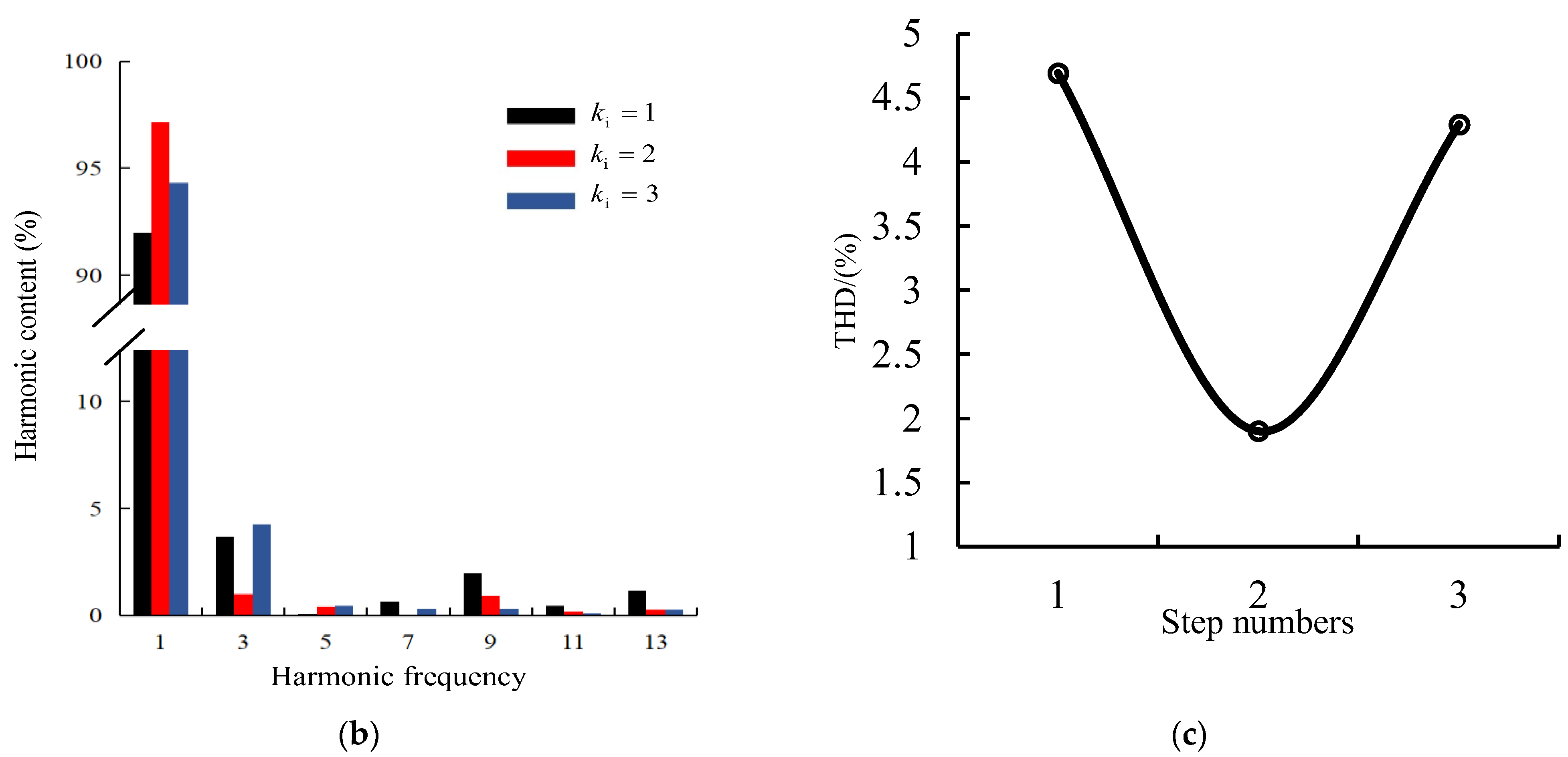
Different finite element simulation models were established for permanent magnets with different numbers of pole steps. The waveform variation and harmonic distribution of the no-load back electromotive force conditions are compared by simulation results. Figure 5a shows the comparison between the no-load back electromotive force waveform of different pole steps and the corresponding standard sine wave. It can be seen that the fitting degree between the second pole step and its corresponding sine function is the highest. As the number of pole steps increases, the waveform of the no-load back electromotive force gradually deviates from the sine wave. Figure 5b shows the comparison of the harmonic content of the back electromotive force for different pole steps. Compared with the traditional flat-type permanent-magnet structure, the number of pole steps is 1; when the number of pole steps is 2, the harmonic content of the back electromotive force is the lowest. Figure 5c shows the total harmonic distortion of the no-load back electromotive force waveform. decreases from 4.69% for a first pole step to 1.9% for a second pole step, while it increases to 4.29% for a third pole step, which is consistent with the harmonic analysis shown in Figure 5b. Therefore, when the number of pole steps is 2, the 3rd, 7th, and 9th harmonic components are significantly reduced, is reduced by 50%, and the no-load back electromotive force waveform is effectively optimized.

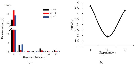
Figure 5.
The effect of the number of steps on the no-load back EMF characteristics: (a) comparison of no-load back EMF waveforms with different step numbers; (b) comparison of no-load back EMF harmonic analysis with different step numbers; and (c) comparison chart of magnetic poles with different step numbers.
3.2. Cogging Torque Optimization
The amplitude of the cogging torque is inversely proportional to the harmonic order, and the size of each harmonic of different slot-pole combinations is different. With indicating the number of cycles of the fundamental wave of the cogging torque, then there is
If the of the cogging torque increases, its amplitude will decrease. Therefore, the method of using stator slot opening to change is adopted. According to Equation (10), the more auxiliary slots there are, the larger the and the smaller the cogging torque. However, excessive auxiliary slots will reduce the air-gap flux density and are also affected by the processing technology. Generally, two rectangular auxiliary slots are opened [24]. Figure 6 shows a comparison of the cogging torque before and after opening two auxiliary slots in the stator.
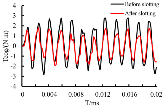
Figure 6.
Comparison of cogging torque before and after slotting.
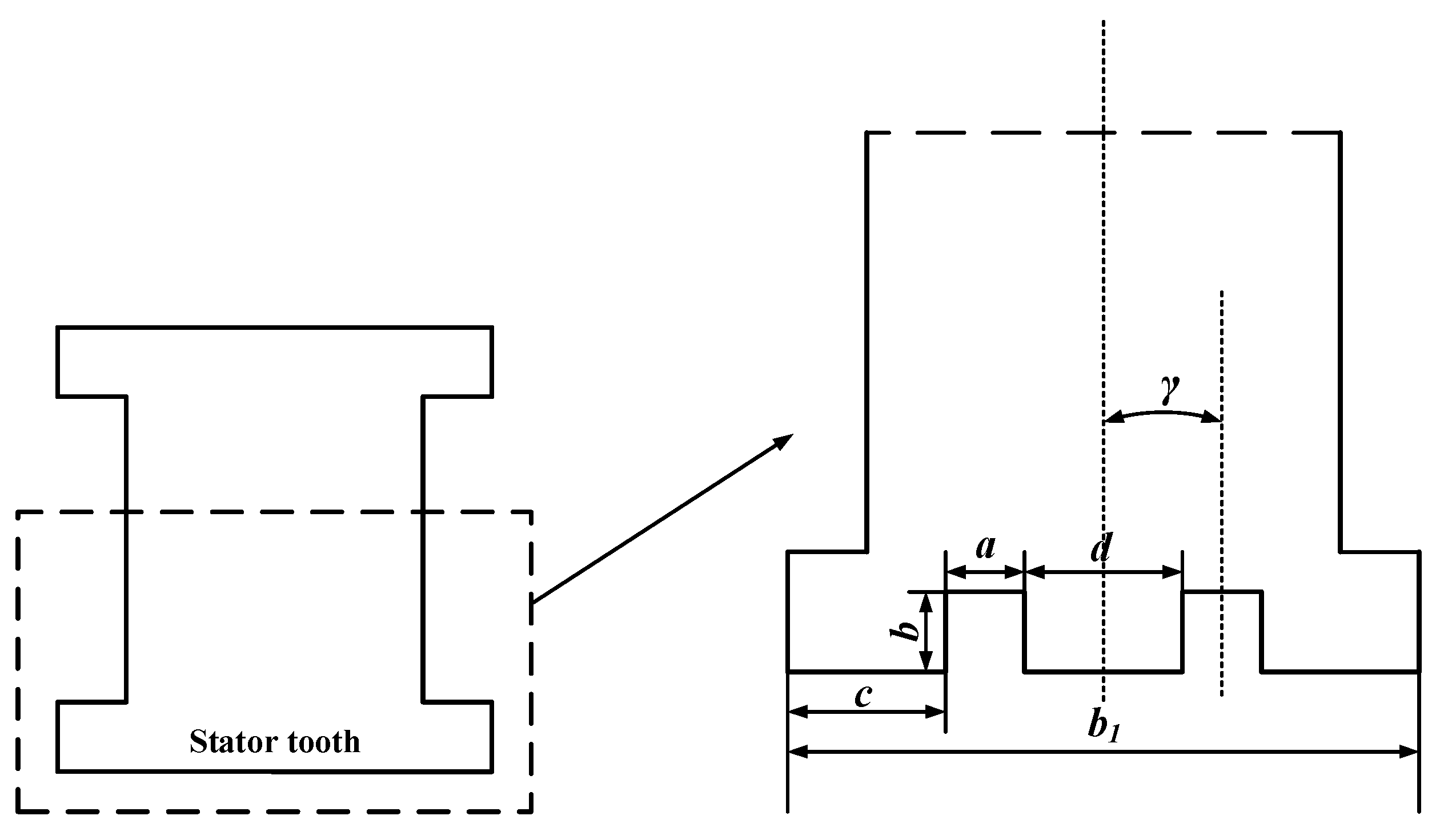
In order to further reduce the cogging torque, it is necessary to consider the auxiliary slot parameters that affect the magnitude of the cogging torque to achieve the optimal weakening effect. When opening auxiliary slots on the stator, in order to avoid introducing new harmonics as much as possible, the two auxiliary slots are generally symmetric about the centerline axis of the stator teeth. Figure 7 shows a model of the stator with two open auxiliary slots, where γ represents the angle between the centerline of the stator tooth and the centerline of one of the auxiliary slots, which is used to determine the position of the auxiliary slot opening.

Figure 7.
Schematic diagram of opening auxiliary slots in the stator.
The air-gap length distribution function before stator slotting can be expressed as
where represents the air-gap length between the stator and rotor, refers to the depth of the stator slot, represents the width of the stator tooth, and denotes the distance between the centerlines of two adjacent stator teeth.
By performing a Fourier decomposition of , there is
When the number of auxiliary slots is two, the air-gap length distribution function can be expressed as
where a represents the width of the auxiliary slot, b represents the depth of the auxiliary slot, c represents the distance between the outer edge of the auxiliary slot and the corresponding stator tooth edge, and d represents the distance between the inner edges of the two auxiliary slots.
By performing a Fourier decomposition of the equation
and
The above equation shows that the width, depth, and position of the auxiliary slots all affect the air-gap length distribution function and, thus, the magnitude of the cogging torque. Therefore, selecting appropriate parameters for the auxiliary slots is crucial to effectively reduce the amplitude of the cogging torque.
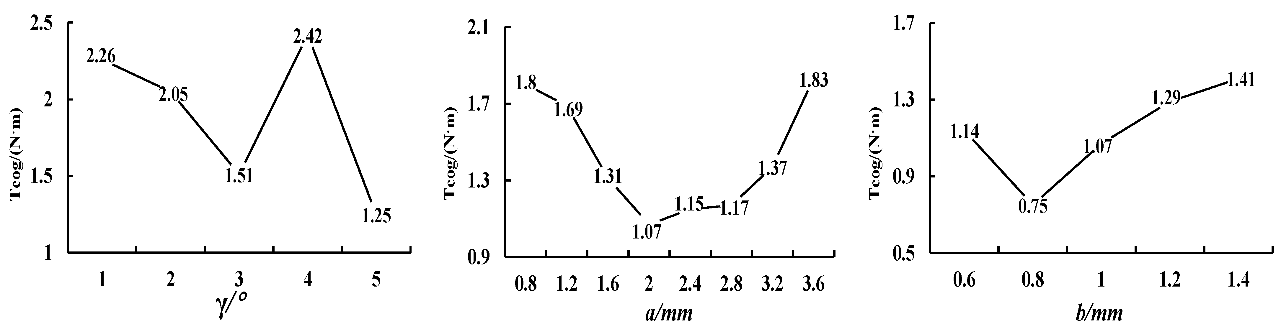
By building finite element models of motors with different slot depths, widths, and locations and solving them, the optimal structural parameters of the auxiliary slots can be found. First, the positions of the two auxiliary slots are studied. The width a of the auxiliary slot is set to 1.4 mm, and the depth b is set to 1 mm. The angle γ between the centerline of the auxiliary slot and the centerline of the stator tooth is defined, and γ is varied in steps of 1° within the range of 1° to 5°. When γ = 5°, the cogging torque reaches its minimum value, but the slot is located at the edge of the stator tooth, which is difficult to machine, and the cogging torque is unstable when optimizing other parameters later. Therefore, γ = 3° is chosen as the slot location. Next, with the depth of the auxiliary slot set to 1 mm and γ set to 3°, the width a of the auxiliary slot is optimized in steps of 0.4 mm within the range of 0.8 mm to 3.6 mm. The minimum value of the cogging torque, 1.07 N·m, is obtained when a = 2 mm. Finally, with γ = 3° and a = 2 mm, the width b of the auxiliary slot is optimized in steps of 0.2 mm within the range of 0.6 mm to 1.4 mm. The minimum value of the cogging torque, 0.75 N·m, is obtained when b = 0.8 mm. The variation in peak cogging torque is shown in Figure 8.
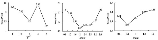
Figure 8.
Line charts of cogging torque variation with different parameters.
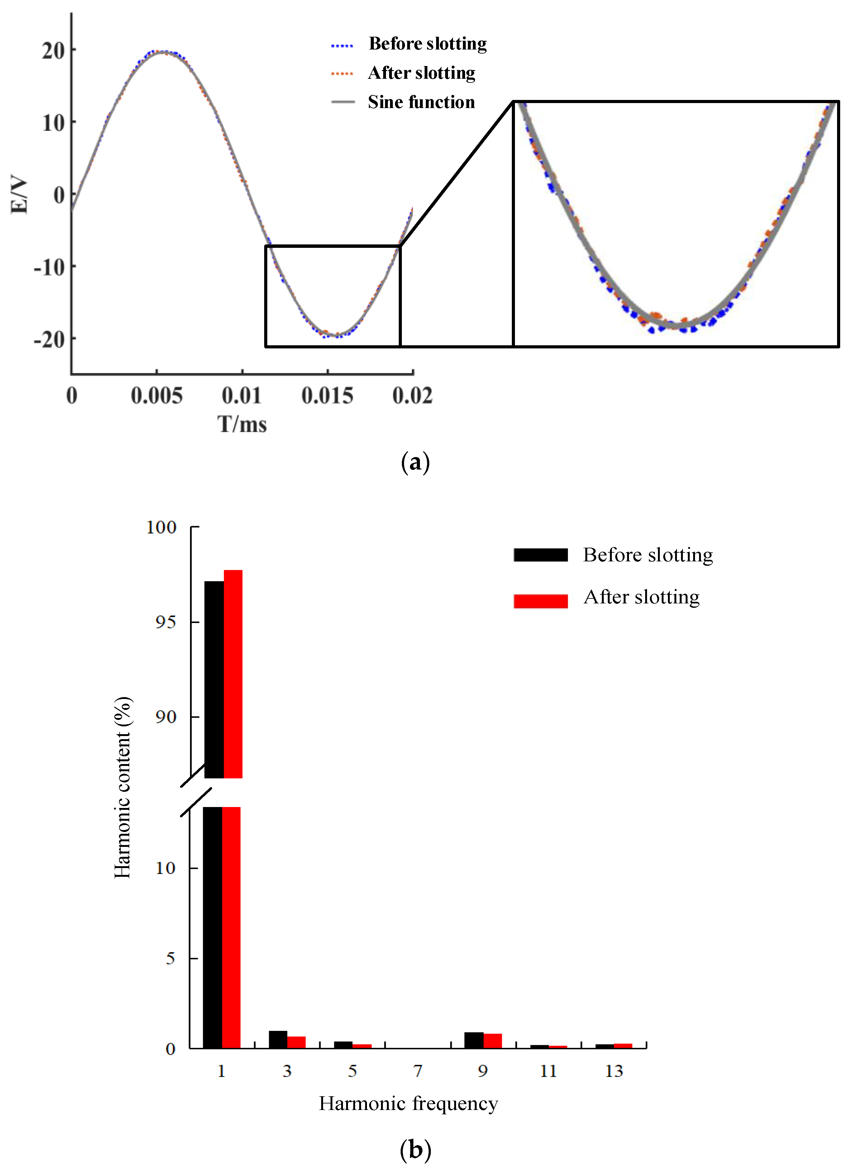
Therefore, when the stator auxiliary slots with γ = 3°, a = 2 mm, and b = 0.8 mm are selected, the minimum peak cogging torque is 0.75 N·m, which is a reduction of 2.05 N·m or approximately 73.2% compared to the cogging torque of 2.8 N·m before slotting, and it is close to the optimal solution. Formula (14) shows that the stator slotting will affect the air-gap flux density function, which in turn affects the waveform of the no-load back electromotive force. Therefore, Figure 9a compares the changes in the no-load back electromotive force waveform before and after slotting, and Figure 9b shows the harmonic changes in the no-load back electromotive force waveform obtained by Fourier analysis. It can be seen that the effect of opening two auxiliary slots in the stator on the waveform of the no-load back electromotive force is small, the content of the third harmonic is reduced from 1% to 0.67%, and is reduced from 1.9% to 1.87%. Therefore, optimizing the stator by opening two auxiliary slots is an effective method for reducing the cogging torque.
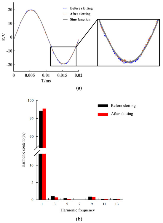
Figure 9.
Performance analysis diagrams of no-load back EMF of the motor before and after opening the auxiliary slot: (a) comparison chart of no-load back EMF waveform before and after slotting and (b) analysis chart of no-load back EMF harmonic content before and after slotting.
3.3. Comparison of Motor Performance before and after Optimization
Based on the above analysis, it is finally determined that the number of pole steps is 2, and the parameters of the stator auxiliary slots are γ = 3°, a = 2 mm, and b = 0.8 mm. A new finite element analysis model is built, and the simulated performance parameters of the motor before and after optimization are shown in Table 2.
Table 2.
Comparison table of motor performance parameters before and after optimization.
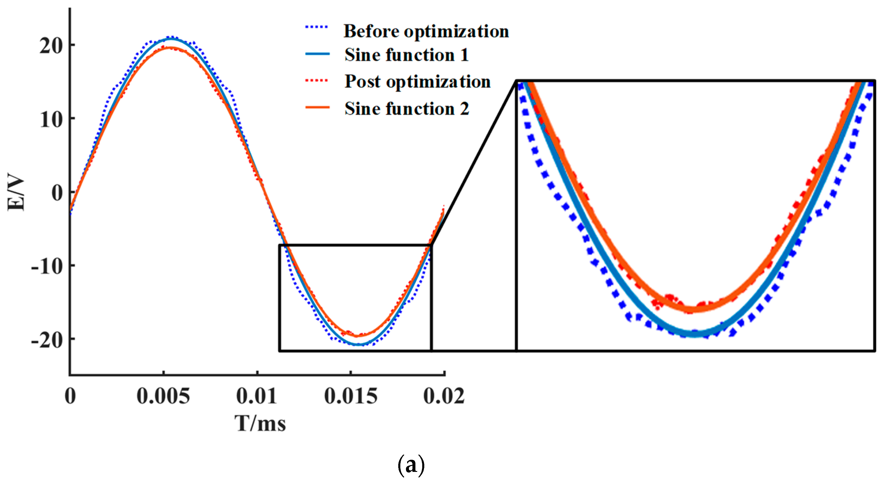
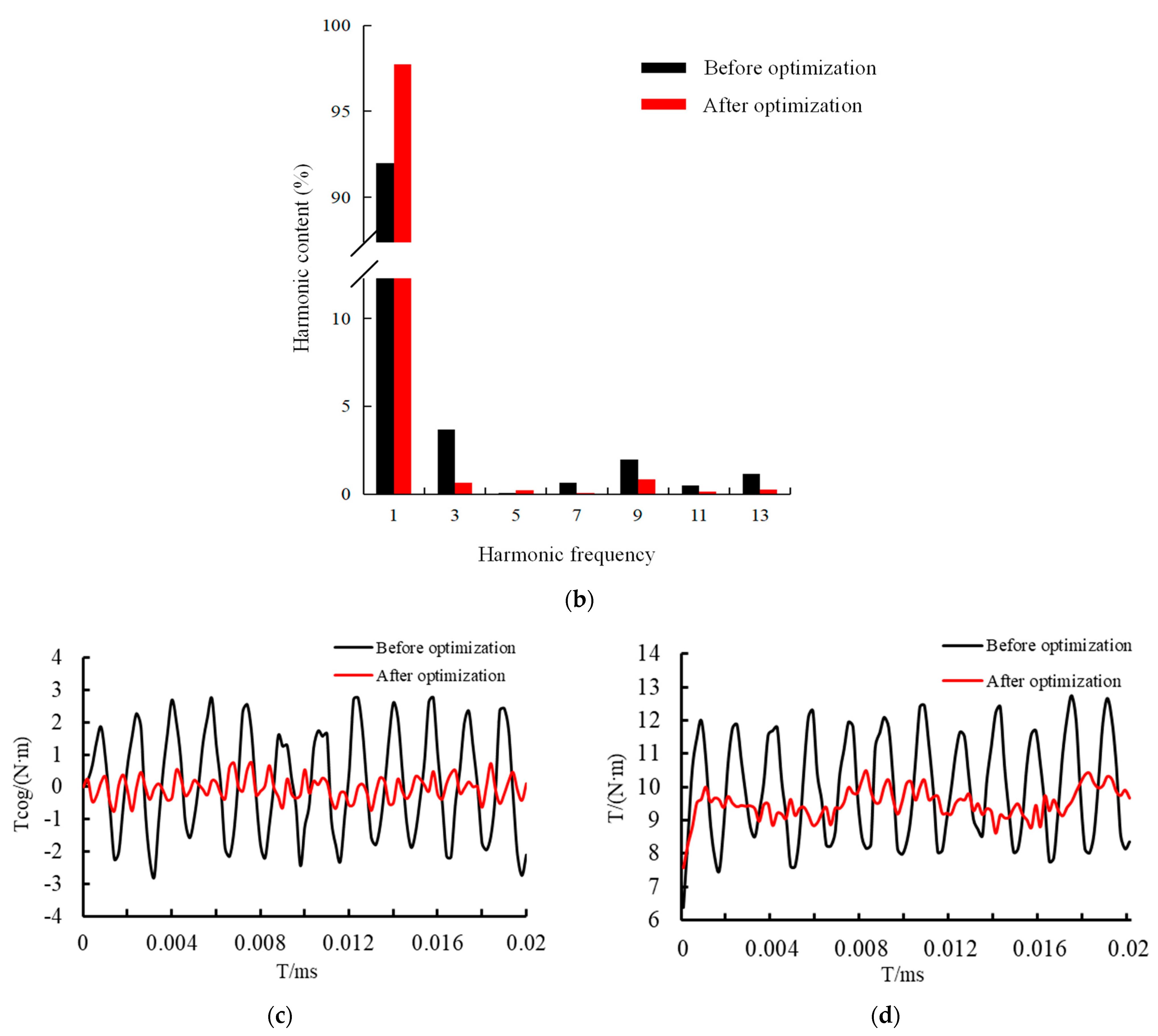
The comparison of the no-load back electromotive force waveforms in Figure 10a shows that the no-load back electromotive force value decreases from 20.4 V to 19.6 V, which is related to the stepped magnetic pole reducing the amount of magnetic pole. However, the fitting degree to the standard sine function waveform is significantly improved. The comparison of the no-load back electromotive force harmonic analysis in Figure 10b shows that the fundamental frequency amplitude of the no-load back electromotive force increases significantly, and all harmonic frequencies are weakened to varying degrees. is reduced from 4.69% to 1.87%, and the distortion rate of the optimized voltage waveform is reduced by 60.13%. The comparison of the cogging torque in Figure 10c shows that the peak cogging torque is reduced from 2.8 N·m to 0.75 N·m after opening the auxiliary slots, and the cogging torque is weakened by 73.2%. The motor output torque changes in Figure 10d show that the output torque fluctuation is large before optimization, with a peak torque of 12.74 N·m and an average output torque of 10 N·m. After optimization, the output torque fluctuation is reduced, with a peak torque of 10.49 N·m and an average torque of 9.50 N·m.
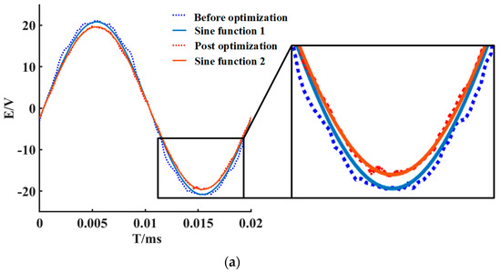

Figure 10.
Comparison of various performances of the motor before and after optimization: (a) comparison chart of no-load back EMF waveform before and after optimization; (b) analysis chart of no-load back EMF harmonic content before and after optimization; (c) comparison of cogging torque before and after optimization; and (d) comparison chart of output torque before and after optimization.
4. Conclusions
In this paper, the disk generator is no longer optimized for a single objective, and a combination method using stepped magnetic poles and stator open auxiliary slots is proposed to improve the performance of the generator. The effects of various different pole-step structures and different auxiliary slot structures on the performance of the generator are comparatively analyzed, and the optimal rotor structure and auxiliary slot parameters are determined based on the distortion rate of the no-load back electromotive force waveform and the magnitude of the cogging torque changes. The following conclusions can be drawn from this study:
- When the permanent magnet is the second-order magnetic pole, the no-load back EMF distortion rate of the motor is minimized from the previous 4.69% to 1.9%.
- Two rectangular auxiliary slots opened by the stator teeth are studied after the improvement in the magnetic pole structure. When the slot width is 2 mm, the slot depth is 0.8 mm, and the angle between the centerline of the auxiliary slots is at an angle of 3° with the centerline of the stator teeth, the peak motor cogging torque is reduced to 0.75 N·m, and the cogging torque is obviously weakened; the is reduced to 1.87%, and the no-load back electromotive force fundamental content rises obviously, and the multiple harmonic content is reduced.
- After the simultaneous improvement in the rotor pole structure and stator tooth structure, the motor output torque pulsation of the motor is reduced, the pulsation coefficient is reduced from 25.27% to 9.79%, and the average value of the torque is reduced from 10 N·m to 9.5 N·m; this is related to the fact that the stepped magnet structure reduces the volume of the permanent magnets on the basis of the original magnets structure.
Overall, the combination of stepped poles and stator auxiliary slots not only improves the sinusoidal waveform of the no-load back electromotive force but also reduces the peak of the cogging torque, which greatly reduces the vibration and noise of the permanent-magnet synchronous dual-rotor statorless magnetically coupled disc motor during operation, and improves its operational stability.
Author Contributions
Conceptualization, Y.C., X.K. and Y.Y.; Methodology, T.G., X.K. and Y.W.; Software, T.G., G.X. and W.Z.; Validation, W.Z.; Investigation, G.X. and Y.Y.; Resources, Z.Q.; Data curation, T.G., X.K. and Y.W.; Writing—original draft, T.G.; Writing—review & editing, Y.C. and Z.Q.; Supervision, T.G., Y.C. and J.X.; Project administration, J.X. and G.W.; Funding acquisition, Y.C. and G.W. All authors have read and agreed to the published version of the manuscript.
Funding
This work was completed under the support of the National Natural Science Foundation of China (grant number 51376096), the “Thirteenth Five-Year Plan” Provincial Key Construction Discipline Project of Jiangsu Province (2016-0802 Mechanical Engineering), and the Jiangsu Engineering Research Center for Wind Energy Application.
Data Availability Statement
Data are contained within the article.
Conflicts of Interest
The authors declare no conflict of interest.
Nomenclature
| Total harmonic distortion | EMF | Electromotive force | |
| The fundamental component of the no-load back electromotive force | The odd-order harmonic components of the no-load back electromotive force | ||
| The magnetic field energy | The position angle | ||
| The distribution function of air-gap magnetic flux density | The magnetic permeability of the air gap | ||
| The mechanical angle of rotation of the motor | The number of pole pairs in the rotor | ||
| The remanent magnetization of the permanent magnet | The pole arc coefficient of the permanent magnet | ||
| The number of stator slots | The Fourier coefficient of the magnetic conductivity function | ||
| The outer radius of the armature | The inner radius of the stator yoke | ||
| The axial length of the armature core | The average diameter of the motor | ||
| The effective length of the armature | The effective air-gap length of the motor | ||
| Number of cycles of the fundamental wave of the cogging torque | Air-gap length distribution function before stator slotting | ||
| The air-gap length between the stator and rotor | The depth of the stator slot | ||
| The width of the stator tooth | The distance between the centerlines of two adjacent stator teeth | ||
| a | The width of the auxiliary slot | b | The depth of the auxiliary slot |
| c | The distance between the outer edge of the auxiliary slot and the corresponding stator tooth edge | d | The distance between the inner edges of the two auxiliary slots |
| The angle between the centerline of the stator tooth and the centerline of one of the auxiliary slots | The number of pole steps |
References
- Huang, Y.K.; Zhou, T.; Dong, J.N.; Guo, B.C.; Zhang, L. A review of axial permanent magnet motor and its research and development. Proc. Chin. Soc. Electr. Eng. 2015, 35, 192–205. [Google Scholar] [CrossRef]
- Li, Y.; Xing, J.; Wang, T.; Lu, Y. Programmable Design of Magnet Shape for Permanent-Magnet Synchronous Motors with Sinusoidal Back EMF Waveforms. IEEE Trans. Magn. 2008, 44, 2163–2167. [Google Scholar] [CrossRef]
- Hua, W.; Cheng, M.; Zhu, Z.Q.; Howe, D. Analysis and Optimization of Back EMF Waveform of a Flux-Switching Permanent Magnet Motor. IEEE Trans. Energy Convers. 2008, 23, 727–733. [Google Scholar] [CrossRef]
- Shokri, M.; Rostami, N.; Behjat, V.; Pyrhonen, J.; Rostami, M. Comparison of Performance Characteristics of Axial-Flux Permanent-Magnet Synchronous Machine with Different Magnet Shapes. IEEE Trans. Magn. 2015, 51, 8115206. [Google Scholar] [CrossRef]
- Liu, J.; Cai, W. Reverse potential harmonic weakening method for automotive built-in permanent magnet drive motor. Micromotor 2018, 51, 7–10. [Google Scholar]
- Wu, J.; Zhao, Q.; Zhuang, B.; Yang, C. A pole shape optimization method for weakening the reverse potential harmonics of permanent magnet synchronous motors. Micromotor 2017, 50, 24–26. [Google Scholar]
- Ding, J.L.; Yu, S.B.; Zhao, H.N.; Xia, P.P. A pole shape optimization method for surface-mounted permanent magnet synchronous motor. Micromotor 2020, 48, 18–21. [Google Scholar]
- Qi, X.D.; Gao, F.Y.; Li, X.F.; Li, Z.J.; Yang, Q.L.; Yuan, C. Optimized design of new eccentric poles for surface-mounted permanent magnet synchronous motors. J. Electron. Meas. Instrum. 2020, 34, 93–100. [Google Scholar] [CrossRef]
- Liu, Y.; Yu, H.; Wang, Y. Establishment of a New Dual Rotor Flux Switching Motor Magnetic Circuit Model and Optimization of No-Load Back EMF. IEEE Trans. Magn. 2019, 55, 7503005. [Google Scholar] [CrossRef]
- Cheng, B.; Pan, G.; Mao, Z. Analytical Calculation and Optimization of the Segmented-Stator Dual-Rotor Axial Flux Permanent Magnet Motors. IEEE Trans. Magn. 2020, 56, 8101709. [Google Scholar] [CrossRef]
- Zhang, X.; Zhang, C.; Yu, J.; Du, P.; Li, L. Analytical Model of Magnetic Field of a Permanent Magnet Synchronous Motor with a Trapezoidal Halbach Permanent Magnet Array. IEEE Trans. Magn. 2019, 55, 8105205. [Google Scholar] [CrossRef]
- Taravat, S.; Kiyoumarsi, A.; Bracikowski, N. Mitigation of cogging torque in transverse-flux permanent-magnet machines with flux concentrators by step skewing of stator pole. IET Electr. Power Appl. 2020, 14, 2378–2388. [Google Scholar] [CrossRef]
- Ma, C.; Xu, Y.; Sun, M.; Zhang, Z. Weakening the Cogging Torque of Permanent Magnet Motor Based on Magnetic Pole Segmentation and Rotor Slotting. Micro Mot. 2022, 55, 42–45. [Google Scholar] [CrossRef]
- Güleç, M.; Yolaçan, E.; Demir, Y.; Ocak, O.; Aydin, M. Modeling based on 3D finite element analysis and experimental study of a 24-slot 8-pole axial-flux permanent-magnet synchronous motor for no cogging torque and sinusoidal back-EMF. Turk. J. Electr. Eng. Comput. Sci. 2016, 24, 262–275. [Google Scholar] [CrossRef]
- Aydin, M.; Gulec, M. A New Coreless Axial Flux Interior Permanent Magnet Synchronous Motor with Sinusoidal Rotor Segments. IEEE Trans. Magn. 2016, 52, 8105204. [Google Scholar] [CrossRef]
- Huang, K.; Li, H.; Zhou, Y. Research on the method of weakening cogging force by using auxiliary slots. J. Electr. Mach. Control 2014, 18, 54–59+66. [Google Scholar] [CrossRef]
- Xu, L.; Xu, Y.; Gong, J. Analysis and Optimization of Cogging Torque in Yokeless and Segmented Armature Axial-Flux Permanent-Magnet Machine with Soft Magnetic Composite Core. IEEE Trans. Magn. 2018, 54, 8106005. [Google Scholar] [CrossRef]
- Xiao, L.; Li, J.; Qu, R.; Lu, Y.; Zhang, R.; Li, D. Cogging Torque Analysis and Minimization of Axial Flux PM Machines with Combined Rectangle-Shaped Magnet. IEEE Trans. Ind. Appl. 2017, 53, 1018–1027. [Google Scholar] [CrossRef]
- Zhao, B.; Gong, J.; Tong, T.; Xu, Y.; Semail, E.; Nguyen, N.-K.; Gillon, F. A Novel Five-Phase Fractional Slot Concentrated Winding with Low Space Harmonic Contents. IEEE Trans. Magn. 2021, 57, 8104605. [Google Scholar] [CrossRef]
- Sun, K.; Tian, S. Multiobjective Optimization of IPMSM with FSCW Applying Rotor Notch Design for Torque Performance Improvement. IEEE Trans. Magn. 2022, 58, 8104909. [Google Scholar] [CrossRef]
- Mohammadpour, A. Winding factor calculation for analysis of back EMF wave form in air-core permanent magnet linear synchronous motors. Electr. Power Appl. 2012, 6, 253–259. [Google Scholar] [CrossRef]
- Wang, X. Permanent Magnet Motor; Chian Electric Power Press: Beijing, China, 2011. (In Chinese) [Google Scholar]
- Wanjiku, J.; Khan, M.A.; Barendse, P.S.; Pillay, P. Influence of Slot Openings and Tooth Profile on Cogging Torque in Axial-Flux PM Machines. IEEE Trans. Ind. Electron. 2015, 62, 7578–7589. [Google Scholar] [CrossRef]
- Wang, Y.; Tang, C.; Yan, G. Suppression of cogging torque of permanent magnet motor by opening auxiliary notches in stator tooth crown. Micromotor 2014, 47, 20–23. [Google Scholar] [CrossRef]


Disclaimer/Publisher’s Note: The statements, opinions and data contained in all publications are solely those of the individual author(s) and contributor(s) and not of MDPI and/or the editor(s). MDPI and/or the editor(s) disclaim responsibility for any injury to people or property resulting from any ideas, methods, instructions or products referred to in the content. |
© 2023 by the authors. Licensee MDPI, Basel, Switzerland. This article is an open access article distributed under the terms and conditions of the Creative Commons Attribution (CC BY) license (https://creativecommons.org/licenses/by/4.0/).