Abstract
To solve the optimization issues of interior permanent magnet synchronous motors (IPMSMs) and ensure a large output torque while minimizing torque ripple and core loss, the multi-objective optimization strategy should be employed. In this study, we took an 8-pole, 48-slot IPMSM as a specimen. First, the width and thickness of the permanent magnet (PM) and the rotor bridge structures were pre-selected as optimization parameters, while torque ripple and core loss were taken as optimization targets. Then, the Taguchi method to perform orthogonal experiments was employed to select the multi-parameter combinations that make the experimental results stable and with little fluctuation. To ensure the optimal results, the function equations were obtained by multivariate nonlinear fitting, while the parameters were optimized by particle swarm optimization (PSO). Finally, the optimal results were verified by the Finite Element Method (FEM). The results show that our proposed hybrid method can provide an optimal design strategy with better performance such as smaller torque ripple and core loss while maintaining a larger output torque.
1. Introduction
With the further improvement of rural roads in China, small agricultural electric passenger and freight vehicles are in high demand. The IPMSM has the characteristics of small size, simple control, large torque, high power density and high efficiency; therefore, it can be used in small agricultural electric passenger and cargo vehicles [1]. Due to the rugged rural roads and as no breakthrough has been made on the lack of battery power density, the requirement of this type of vehicle is to ensure that the vibration is small and the maximum torque and minimum energy consumption are guaranteed at the same time. However, the impacts of vibration and core loss of IPMSM, leading to low efficiency and high loss of the motor, are not comprehensively studied [2]. The motor vibration mainly comes from electromagnetic vibration, which is caused by torque ripple and unbalanced magnetic pull (UMP) of the IPMSM. To achieve multiple objectives such as low torque ripple, high output torque and low power consumption, the stator and rotor parameters of the IPMSM should be optimized. Therefore, the research on motor parameter optimization is of great significance for vibration suppression and reduced energy consumption.
The traditional optimization method is single-objective optimization, which only considers the individual performance of a motor. Many researchers have proposed various methods for motor optimization, including optimization of the stator slot, optimization of the PM and rotor core, optimization of the PM magnetic bridge structure, optimization of the pole arc coefficient and optimization of slot pole coordination [3,4,5]. With optimal thickness of the PM, the amplitude of the fundamental wave of the radial magnetic density is increased and the harmonic order of the radial magnetic density is reduced [6]. Therefore, the vibration of the optimized motor is reduced and the torque is increased. Moreover, the purpose of saving the volume of PMs is achieved. However, it is difficult to obtain the perfect sine of the back EMF by adopting this approach. To obtain the sine degree of no-load back EMF of a surface-mounted PM motor, the uneven air gap structure can be used to optimize the magnetic pole structure of the motor to improve the air gap magnetic density waveform [7], but this method increases the difficulty in machining the rotor structure. Adequate sinusoidal wave air gap magnetic density can be achieved by adopting the eccentric pole cutting technology [8]. Using this method, the torque ripple can be suppressed. However, it cannot ensure the maximum output torque. Another effective way to suppress the motor torque ripple is to use low-magnetic-energy product PM material, which improves the utilization rate of PM and thus reduces the cost of the motor [9,10]. The main drawback is that the output torque of the motor is reduced. Although this single-objective optimization method can greatly improve a certain performance index of the motor, it is always on the premise of sacrificing another aspect of motor performance, which is not conducive to the overall performance improvement of PMSM.
Current PMSM optimization research mainly focuses on multi-objective optimization methods, and the most commonly used multi-objective optimization methods include response surface method [11], intelligent optimization algorithm [12], the Taguchi method [13], etc. In the literature [14], the response surface method was used to obtain the nonlinear relationship between variables and targets, and after comprehensive analysis, the optimal combination of design variables for motor performance was obtained. Intelligent optimization algorithms commonly used in optimization problems of PM motors include genetic algorithm [15], particle swarm optimization [16], etc. The literature [17] proposes a deep learning-based optimization method for PM motor structure. This method trains the model by inputting cross-section images of motor rotor structure and corresponding output performance data, and then selects the optimal combination of design variables based on the trained model. However, this method requires too large data samples, which are time-consuming. In the literature [18], particle swarm optimization (PSO) algorithm based on machine learning was adopted to optimize the motor with permanent magnet structure and air gap length as parameters and motor torque ripple, air gap magnetic density sinusoidal and core loss as optimization objectives. However, machine learning methods usually require many learning samples to achieve the desired optimization accuracy. In view of this, in recent years, some researchers have built a proxy model and then combined the optimization algorithm to find the variable combination that meets the requirements [19]. The literature [20] established a variety of different proxy models to simulate the approximate relationship between design variables and optimization objectives, selected the random forest (RF) proxy model with the best effect and combined with NSGA-II to optimize multiple performance indicators of the motor. Although the agent model combined with intelligent optimization algorithm can effectively find the optimal combination of design variables in the optimal design of a permanent magnet motor, with the increase in the number of design variables, the accurate establishment of the agent model will become more difficult, and the convergence of the optimization algorithm will also make it more difficult to find the optimal value. Considering the excessive design variables, the sensitivity analysis method was used to divide the design variables into sensitive and insensitive layers and then optimize them twice [21]. The results showed that this method could effectively solve the optimization problem of excessive design variables, but only the torque performance of the motor was considered in the optimization process. The literature [12] proposes a three-level optimization structure, which assigns different optimization parameters and objectives to different levels. The results show that the proposed method can provide an optimal design scheme with smaller torque ripple and lower power loss for the IPMSM studied, while significantly reducing the required calculation cost. In order to reduce the calculation time, the classic optimization method is the Taguchi method, which is based on orthogonal experimental design and analysis to find out the optimal combination of design variables. It requires less test time to effectively optimize the motor performance, and has high optimization efficiency. Therefore, the Taguchi method is often applied by designers in the optimization design of mechanical structures. This method is used to optimize the stator groove structure, magnetization direction and hysteresis [22]. By using this method, a set of parameter combinations with minimum groove torque can be obtained. The disadvantage is that the optimal combination of parameters cannot be obtained. Although the gear groove torque of V-type PMSM is reduced by optimizing rotor parameters, the selection and combination of design optimization parameters are limited, and the optimal solution cannot be obtained [23].
In this paper, a hybrid multi-objective optimization scheme based on the Taguchi method and PSO algorithm is proposed to solve the problem that the Taguchi method cannot obtain the optimal parameter combination due to the large horizontal span of adjacent values of the design space. This method makes use of the characteristics of the Taguchi method, such as less computation time, high optimization efficiency and strong optimization ability of particle swarm optimization algorithm, which make up for the shortcomings of the method. The hybrid multi-objective optimization algorithm was used to optimize the rotor structure of the motor and the output torque, torque ripple and electromagnetic loss of the motor. The rest of this paper is structured as follows. Section 2 introduces the optimization method. Section 3 details the finite element simulation experiment. In Section 4, the finite element simulation results are discussed. Section 5 provides a comprehensive summary of the article.
2. Methodology
2.1. Finite Element Model of IPMSM
In this study, an 8-pole, 48-slot IPMSM was taken as a specimen for optimization analysis. The relevant parameters of the motor are shown in Table 1. According to the parameters in Table 1, the PMSM finite element model is established, which is shown in Figure 1.

Table 1.
Main parameters of PMSM.
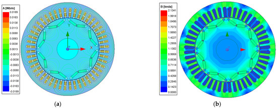
Figure 1.
IPMSM FEM model. (a) Magnetic flux of IPMSM. (b) Magnetic field density of IPMSM.
2.2. Optimization Parameter Pre-Selection
Contemporary design optimization research on IPMSM mainly focuses on the rotor magnetic bridge structure and the amount of PM (PM thickness and width). Therefore, we selected the PM thickness Tmag, PM width Wmag, magnetic bridge width Rib, magnetic bridge radial length HRib, PM radius D1, magnetic bridge width B1, magnetic bridge spacing O1 and the distance O2 between the PM slot and the axial plane as multi-optimal variables. The specific parameters are shown in Figure 2.
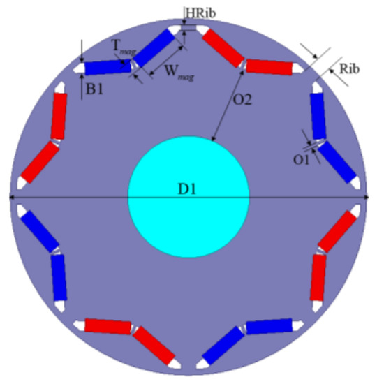
Figure 2.
PMSM optimization parameters.
To understand the influence of each optimization parameter on the motor torque ripple and core loss, we changed each parameter in turn within the preselected range of parameters, conducted simulation analysis and observed the variation law of motor torque ripple and core loss. The effects of each parameter on the motor output torque, torque ripple and core loss are shown in Figure 3a–h.
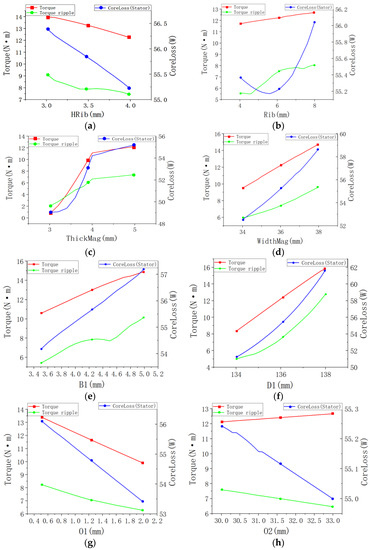
Figure 3.
(a–h) Effects of optimized parameters on output torque (torque ripple) and core loss.
According to the results in Figure 3 (red and green are the output torque and torque ripple, respectively), with the increase in the amount of PM, the output torque and torque ripple of the motor will increase. When the thickness of the PM is less than 3.5 mm, the torque ripple of the motor is too large and exceeds the output torque. At this time, the motor may not work normally. When the thickness of the motor is between 3.5 mm and 4 mm, the output torque of the motor rises rapidly. With the increase in the thickness, the torque ripple increases slowly. With the increase in magnetic bridge width Rib, PM fixed circle radius D1 and magnetic bridge width B1, the motor output torque and torque ripple generally show an upward trend. On the contrary, with the increase in magnetic bridge radial length HRib and magnetic bridge spacing O1, the motor output torque and torque ripple both show a downward trend. When the distance between the PM slot and the shaft surface increases, the motor output torque shows an upward trend and torque ripple shows a downward trend. Therefore, when designing the built-in PM synchronous motor, the distance between the PM and the shaft should be increased as much as possible.
According to the analysis of the results in Figure 3, with the increase in the amount of PM (PM thickness Tmag and width Wmag), PM radius D1 and magnetic bridge width B1, the motor core loss increases. With the increase in the width of the magnetic bridge Rib, the core loss of the motor decreases first and then increases, so selecting a suitable width of the magnetic bridge can reduce the core loss and temperature rise loss of the motor. As the radial length of the magnetic bridge HRib, the magnetic bridge spacing O1 and the distance between the PM slot and the axial surface O2 increase, the motor core loss decreases. Therefore, when we design the IPMSM, larger values should be selected, except for HRib and Rib.
2.3. Taguchi Method Optimization
As a local optimization methodology, the Taguchi method can optimize multiple motor performance parameters at the same time, with fewer tests, lower costs and a shorter design cycle. By using the designed orthogonal test, design time and cost can be saved, and the optimal parameter combination can be found at the fastest speed [24]. Moreover, it can reduce the influence of various noise factors.
Preliminary selection of these parameters should be carried out in advance to ensure that there is no interference in all parts of the motor within this range. The value range of this parameter is shown in Table 2.
Table 2.
Value range of parameters to be optimized.
An orthogonal experiment can optimize the level of multiple factors, with the important characteristics of uniformity and unity, which can greatly reduce the number of experiments and lower the cost of experiments. An orthogonal table is the key to an orthogonal experiment.
An orthogonal table can usually be expressed as Ls(Ak), where L represents the orthogonal table, S represents the number of experiments, A is the number of levels and K represents the number of optimization parameters. The preliminary simulation of these parameters in advance shows that the thickness of PM Tmag, the width of PM Wmag, the width of magnetic bridge B1 and the radius of PM circle D1 have close positive effects on the motor’s output torque (Tavg), torque ripple (Tr) and core loss (Ls), so the above four parameters can be integrated into a combined parameter WTBD. The radial length of the magnetic bridge HRib and the distance between the magnetic bridges O1 have a negative impact on the motor output torque, torque ripple and core loss. Therefore, the above two parameters are integrated into a combined parameter H0, which can greatly reduce the number of orthogonal experiments and save simulation time. It not only reduces the cycle of optimization design, but also improves the efficiency of motor optimization. Therefore, four optimization parameters (Rib, O2, WTBD, H0) are selected for the orthogonal experiment.
2.4. Particle Swarm Optimization (PSO)
The combination of PSO algorithm and selection operator is realized by selecting the optimal value Pg of the original particle swarm. Each particle is given a probability of being selected according to the fitness of all particles, and then these particles are selected according to the probability. The selected particles are taken as Pg to ensure the diversity of the particle swarm.
Combination of PSO algorithm and crossover operator: Particles can be crossed in pairs according to the fitness during the operation of the algorithm, so that the algorithm can introduce new particles during the operation of the algorithm. The position of the new individual is calculated by the following formula:
where x1(t) and x2(t) are the particles selected for hybridization, and rand(0, 1) is the random vector obtained in the interval [0, 1].
The speed formula of the next generation is:
where a new velocity is generated by the hybrid operation and finally replaces the original velocity vector. In general, the hybridization operation not only enables the valuable information of the previous generation to be fully inherited by the offspring, but also greatly improves the population diversity and convergence speed.
The global optimum Pg attracts all particles, making them gather, and the loss of diversity of the population is inevitable. Therefore, a mutation operator is introduced to test the distance between all particles and the current optimum. When the distance is less than a certain value, a certain percentage of particles can be randomly selected for random initialization, and one or more dimensions of particles can be re-initialized according to the mutation probability. The procedure of PSO is that these particles can find the optimum value one more time and the population can achieve the goal of constantly improving the diversity of characteristics. Therefore, it can prevent premature convergence of the algorithm due to local deadlock.
3. Finite Element Simulation Experiment
3.1. Implementation of Taguchi Method
The Taguchi orthogonal experiment was implemented based on the level of parameter optimization in Table 3, and the results are shown in Table 4.
Table 3.
Optimization level of different parameters.
Table 4.
orthogonal experiment.
3.2. Implementation of Objective Function Fitting
Since the Taguchi method has a large horizontal span for adjacent values of the design space, the optimal parameter combination cannot be obtained. Therefore, we further optimized the optimization results of the Taguchi method. Using the experimental data in Table 4 as samples, the functions Tavg, Tr and Ls are fitted by multivariate nonlinear fitting. The fitting results are as follows:
3.3. Implementation of PSO
For the main parameters of PSO, we set the number of particles to 100, the number of iterations to 200, the knowledge learning factor to 1.49 and the particle social cognitive learning factor to 1.49. We set ωmax = 0.9, ωmin = 0.4 and other parameters to keep the default values, and performed multi-objective optimization for the functions of Tavg, Tr and Ls. The iterative convergence process is shown in Figure 4. The optimization goal is to make the parameters as large and as small as possible.
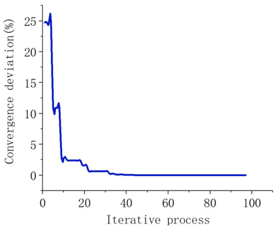
Figure 4.
Particle swarm iteration process.
4. Results and Discussions
Table 5 shows the parameter combination before and after optimization, and the finite element software is used for simulation verification. In Figure 5a,b are the FEM flux and flux density map of the final motors. In addition, the motor’s initial FEM and the optimized Taguchi method and PSO algorithm FEM were simulated and analyzed, and the results of motor torque ripple, iron core loss and copper loss were compared, as shown in Figure 5.
Table 5.
Comparison of optimization parameters.
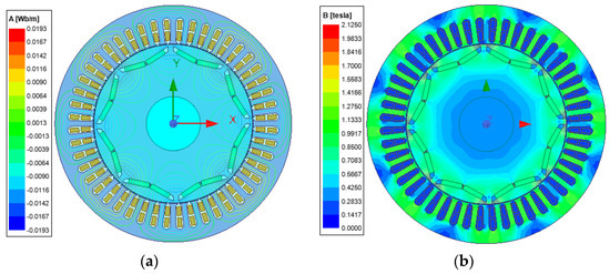
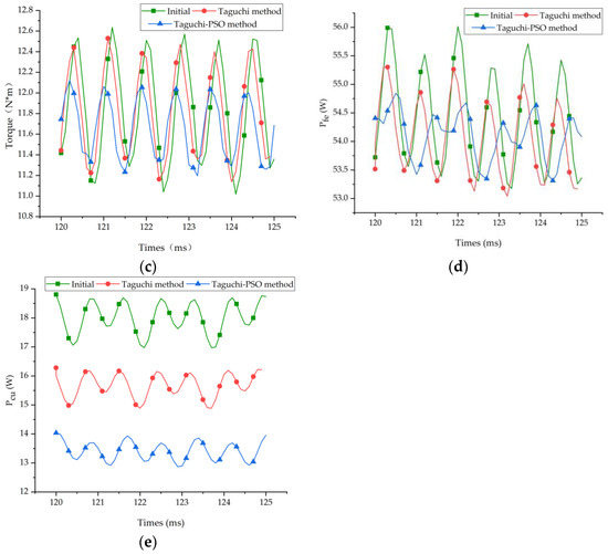
Figure 5.
Performance comparison of the initial motor and the optimized motor: (a) magnetic flux of IPMSM; (b) magnetic field density of IPMSM; (c) comparison of torque ripple; (d) comparison of core loss; (e) comparison of copper loss.
As can be seen from Table 6, after optimization with the Taguchi method, the motor torque ripple is reduced to 1.41 (N * m), the optimization rate is 14%, the core loss is reduced by 0.68% and the motor winding copper loss is reduced by 12.17%. The PSO algorithm is used to optimize the optimization results of the Taguchi method. The results are as follows: the PM consumption of the motor is reduced by 11.7%, the torque ripple of the motor is reduced by 45.7%, the core loss and winding copper loss are reduced by 0.44% and 24.9%, respectively, and the motor efficiency is increased by 0.31%. From the comparison of results, it can be seen that the hybrid multi-objective optimization scheme based on the combination of the Taguchi method and the PSO algorithm effectively reduces the torque ripple and PM consumption of the motor, and also improves the motor loss and efficiency. Therefore, it is feasible to optimize IPMSM motor parameters using the Taguchi method and the particle swarm optimization algorithm.
Table 6.
Optimization results.
5. Conclusions
This paper presents a hybrid multi-objective optimization scheme combining the Taguchi method and PSO algorithm. First, the eight selected parameters were preliminarily simulated, and the parameters with the same influence were recombined to form four parameter combinations. Using the designed orthogonal test can save a lot of test time. Second, the Taguchi method was used for the orthogonal test to screen out the stable and low volatility parameter combinations. In order to obtain the optimal result, the function equation was obtained by multivariate nonlinear fitting. Then, the PSO algorithm was used to optimize the parameters to obtain the optimal parameter combination to make up for the shortcomings of the Taguchi method. Finally, the Finite Element Method was used to verify the optimization results. The results show that the hybrid multi-objective optimization scheme based on the combination of the Taguchi method and PSO algorithm effectively improves the shortcomings of the Taguchi method and has high optimization efficiency. In future work, a prototype will be made according to the optimized parameters and experiments will be carried out to further verify the accuracy and effectiveness of the proposed hybrid method.
Author Contributions
Conceptualization, Y.Y. and P.Z.; methodology, Y.Y.; software, P.Z.; writing—original draft, Y.Y. and P.Z. writing—review and editing, Y.Y., Y.H. (Yong Hao), D.Z., Y.H. (Yiming Hu), B.Z. and H.Y. All authors have read and agreed to the published version of the manuscript.
Funding
This research was supported in part by the National Natural Science Foundation of China (grant no. 52067006, 52162044), in part by the foreign expert Bureau of the Ministry of Science and Technology of China (grant no. G2021022002L), in part by the Long-Term Project of Innovative Leading Talents in the “Double Thousand Plan” of Jiangxi Province (jxsq2019101027) and by the Key Research Program of Jiangxi Province (grant no. 20212BBE51014).
Data Availability Statement
Not applicable.
Conflicts of Interest
The authors declare no conflict of interest.
References
- Chang, L.-K.; Wang, S.-H.; Tsai, M.-C. Demagnetization Fault Diagnosis of a PMSM Using Auto-Encoder and K-Means Clustering. Energies 2020, 13, 4467. [Google Scholar] [CrossRef]
- Ullah, Z.; Lodhi, B.A.; Hur, J. Detection and Identification of Demagnetization and Bearing Faults in PMSM Using Transfer Learning-Based VGG. Energies 2020, 13, 3834. [Google Scholar] [CrossRef]
- Shen, Y.; Zhu, Z.Q. Analysis of electromagnetic performance of Halbach PM brushless machines having mixed grade and unequal height of magnets. IEEE Trans. Magn. 2013, 49, 1461–1469. [Google Scholar] [CrossRef]
- Duan, S.; Zhou, L.; Wang, J. Flux weakening mechanism of interior permanent magnet synchronous machines with segmented permanent magnets. IEEE Trans. Appl. Supercond. 2014, 24, 5001053. [Google Scholar] [CrossRef]
- Zhou, Y.; Li, H.; Meng, G.; Shou, S.; Cao, Q. Analytical calculation of magnetic field and cogging torque in surface-mounted permanent-magnet machines accounting for any eccentric rotor shape. IEEE Trans. Ind. Electron. 2015, 62, 3438–3447. [Google Scholar] [CrossRef]
- Ni, Y.-Y.; Cui, Z.-S. Magnetic field analysis and optimization of slotless permanent magnet machines with combined magnetization. Electr. Mach. Control 2020, 24, 79–87. [Google Scholar]
- Zhang, B.-Y.; Jia, Y.-Q.; Li, K.; Feng, G.-H. Study on magnetic pole structure of surface mounted PMSM. Electr. Mach. Control. 2014, 18, 43–48. [Google Scholar]
- Qi, X.; Wu, X. Optimization Method of Eccentricity Cutting Technology for Surface-mounted Permanent Magnet Motor. Large Electr. Mach. Hydraul. Turbine 2019, 6, 25–29. [Google Scholar]
- Kim, H.J.; Kim, D.Y.; Hong, J.P. Structure of concentrated flux-type interior permanent-magnet synchronous motors using ferrite permanent magnets. IEEE Trans. Magn. 2014, 50, 8206704. [Google Scholar] [CrossRef]
- Onsal, M.; Cumhur, B.; Demir, Y.; Yolacan, E.; Aydin, M. Rotor design optimization of a new flux-assisted consequent pole spoke-type permanent magnet torque motor for low-speed applications. IEEE Trans. Magn. 2018, 54, 8206005. [Google Scholar] [CrossRef]
- Zhu, H.; Shen, S.; Wang, X. Multiobjective Optimization Design of Outer Rotor Coreless Bearingless Permanent Magnet Synchronous Motor. IEEE J. Emerg. Sel. Top. Power Electron. 2021, 9, 5489–5498. [Google Scholar] [CrossRef]
- Sun, X.; Shi, Z.; Lei, G.; Guo, Y.; Zhu, J. Multi-objective design optimization of an IPMSM based on multilevel strategy. IEEE Trans. Ind. Electron. 2021, 68, 139–148. [Google Scholar] [CrossRef]
- Karimpour, S.R.; Besmi, M.R.; Mirimani, S.M. Optimal design and verification of interior permanent magnet synchronous generator based on FEA and Taguchi method. Int. Trans. Electr. Energy Syst. 2020, 30, e12597. [Google Scholar] [CrossRef]
- Chen, Y.; Zhu, X.; Quan, L.; Han, X.; He, X. Parameter Sensitivity Optimization Design and Performance Analysis of Double-Salient Permanent-Magnet Double-Stator Machine. Trans. China Electrotech. Soc. 2017, 32, 160–168. [Google Scholar]
- Hasanien, H.M.; Abd-Rabou, A.S.; Sakr, S.M. Design optimization of transverse flux linear motor for weight reduction and performance improvement using response surface methodology and genetic algorithms. IEEE Trans. Energy Convers. 2010, 25, 598–605. [Google Scholar] [CrossRef]
- Lee, J.H.; Kim, J.W.; Song, J.Y.; Kim, D.W.; Kim, Y.J.; Jung, S.Y. Distance-based intelligent particle swarm optimization for optimal design of permanent magnet synchronous machine. IEEE Trans. Magn. 2017, 53, 7206804. [Google Scholar] [CrossRef]
- Sasaki, H.; Igarashi, H. Topology optimization of IPM motor with aid of deep learning. Int. J. Appl. Electromagn. Mech. 2019, 59, 87–96. [Google Scholar] [CrossRef]
- Guo, X.; Zhang, B.-Y.; Feng, G.-H. Multi-objective optimization of low speed high torque direct drive PMSM based on hybrid particle swarm optimization. J. Mech. Electr. Eng. 2018, 35, 1214–1219. [Google Scholar]
- Duan, Y.; Ionel, D.M. A review of recent developments in electrical machine design optimization methods with a permanent-magnet synchronous motor benchmark study. IEEE Trans. Ind. Appl. 2013, 49, 1268–1275. [Google Scholar] [CrossRef]
- Pan, Z.; Fang, S. Combined random forest and NSGA-II for optimal design of permanent magnet arc motor. IEEE J. Emerg. Sel. Top. Power Electron. 2021, 10, 1800–1812. [Google Scholar] [CrossRef]
- Zhu, X.; Shu, Z.; Quan, L.; Xiang, Z.; Pan, X. Multi-objective optimization of an outer-rotor V-shaped permanent magnet flux switching motor based on multi-level design method. IEEE Trans. Magn. 2016, 52, 8205508. [Google Scholar] [CrossRef]
- Xia, J.; Yu, B.; Huang, W. Optimization of the Structure to Reduce the Cogging Torque in PM Motors. Electr. Eng. 2009, 12, 23–25. [Google Scholar]
- Wang, Q.-J.; Zhou, J.; Qian, Z.; Li, G.-L.; Chen, X.; Jiang, H.; Cheng, Y. Optimizing symmetry to reduce the cogging torque of the V-type interior permanent magnet machines. Electr. Mach. Control. 2020, 24, 55–62. [Google Scholar]
- Guo, H.; Qian, H. Robust Design for Reducing Torque Ripple in Permanent Magnet Synchronous Motor. CSEE 2012, 32, 88–95. [Google Scholar]
Disclaimer/Publisher’s Note: The statements, opinions and data contained in all publications are solely those of the individual author(s) and contributor(s) and not of MDPI and/or the editor(s). MDPI and/or the editor(s) disclaim responsibility for any injury to people or property resulting from any ideas, methods, instructions or products referred to in the content. |
© 2022 by the authors. Licensee MDPI, Basel, Switzerland. This article is an open access article distributed under the terms and conditions of the Creative Commons Attribution (CC BY) license (https://creativecommons.org/licenses/by/4.0/).