1. Introduction
Environmental degradation, climate change, and significant dependence on energy imports pose a threat to the sustainable development of Europe and the world [
1]. To overcome these challenges, it is necessary to create new energy-efficient equipment for energy production from biomass [
2]. This is stated in the European Union Deal. According to the European Green Deal, it is necessary to reduce greenhouse gas emissions by 55% (from 1990 to 2023) and ensure sustainable economic growth without increasing the use of fossil fuel resources [
3]. Reducing greenhouse gas emissions requires an increase in the share of renewable sources in energy production [
4] and the development of new types of relevant equipment [
5].
Strict regulations about the pollution of traditional hydrocarbon fuels are the reason for the rapid growth of investigations in bioenergetics, particularly in energy produced from biomass [
6]. Solar–biomass integrated energy systems for clean electricity and liquid hydrogen production have been deeply researched for the last 10 years [
7]. Technologies for hydrogen production through the thermochemical conversion of biomass are also gaining relevance [
8]. Biomass makes up 10% of the general volume of the primary resources in the world and is the fourth most significant type of fuel [
9]. The wood and waste products of its mechanical (shavings and chips) and technical (lignin) processing, peat, and agro wastes (corn stalks, sunflower stems and receptacles, husk, nut shells, wheat straw) are promising types of biomass for energy. Although world agriculture is characterized by significant stocks of biomass and its wastes, biomass energy production is minor (in some countries, it does not exceed 4%) [
10].
If we look at methods of biomass conversion into energy, we will see that energy production by the thermochemical conversion of biomass, particularly by gasification, is receiving intensive development [
11]. This also fully applies to green hydrogen production through the gasification of decarbonized biomass [
12]. The main advantages of gasification are the simplicity of the process management, high ecology indicators (low CO and NO
x content in the combustion products), the low sensitivity to the moisture content in raw materials, and the minimal efforts needed for their pre-treatment [
13]. Also, modern gasification plants are characterized by a high coefficient of performance (CoP) (over 80%) [
14].
Nevertheless, the existing availability of relatively cheap fossil fuels motivates scientists to look for ways of reducing the cost of combustible gas production and the energy created from it [
15]. One of the ways is filtration burning in a superadiabatic mode, which makes it possible to gasify wet biomass more effectively, producing energetic gas and liquid hydrocarbons [
16].
Filtration burning in a superadiabatic mode is made by supporting combustion inside a porous medium, which intensifies heat circulation in a reaction zone [
17]. The mentioned process is a promising non-catalytic partial thermal fuel oxidation method for combustible gas production, particularly syngas [
18]. The heat transfer and convection combustion regimes of porous systems with the filtration of the heat carrier is one of the complex problems in modern combustion process’ chemical thermodynamics [
19]. Dorofeenko et al. [
20] and San José et al. [
21] reported that the porous medium could be in the form of a pseudoliquified layer. Salganskii et al. [
22] noted that the porous medium could be in the form of a solid layer.
The spouted-bed combustor is the best example of an installation with a pseudoliquified layer, which is characterized by a high velocity of the incoming blowing gases, which excites the fuel particles, providing the needed pseudoliquification [
21].
Combustion in a fixed bed gasifier is conducted inside the voids of a porous matrix either by filtration combustion or by stationary flame combustion [
23]. At the same time, the heat exchange between the porous medium and combustible gases keeps the heat inside the solid matrix, and for that reason, the flame temperature is higher than the adiabatic temperature. In this case, the energetic CoP could be higher than 90% [
24].
Hybrid filtration combustion combines the properties of the solid fuel (biomass, coal, peat) gasification process and filtration combustion in an inert porous medium (the propagation of the exothermal waves of reactions in a porous medium) [
25] when the inert solid medium is partially substituted by fuel [
26].
The fundamentals of porous medium combustion, its applications, and research progress are presented in [
27,
28,
29].
Particularly, the influence of the type and properties of a solid inert material (hollow spheres) on the heat effect during filtration combustion is presented in [
27]. The study explores how the incorporation of hollow spheres affects heat transfer, combustion efficiency, and emissions in the combustion system. The findings shed light on the potential benefits and drawbacks of employing such a type of inert material in filtration combustion, providing valuable insights for optimizing combustion systems and enhancing energy efficiency.
The numerical simulation of hybrid filtration combustion is presented in [
28,
29]. In particular, the simulation of filtration combustion of gas in a porous burner has been carried out within the framework of the two-temperature thermal diffusion model presented in [
28]. The research advances the understanding of combustion dynamics in radiation burners and opens up new possibilities for energy-efficient and environmentally friendly heating processes. Hybrid filtration combustion waves in a porous media have been numerically analysed for biomass and methane–air mixtures in [
29]. The research investigates the effect of various parameters, such as particle size, gas velocity, and temperature, on combustion efficiency and emissions during the hybrid process. The results provide valuable insights into the thermal behaviour and pollutant formation during biomass combustion, thus contributing to the development of sustainable and clean energy solutions.
Hybrid filtration combustion has been studied for such types of gasification: coal gasification [
20], plant biomass gasification [
25], wood gasification [
30], and gasification of mixtures of polyethylene and wood [
31]. The description of this process by mass and energy equations is given in [
32].
There are a number of scientific works in which the authors have investigated the gasification conditions that provide the highest H2 and CO contents in the gas. They studied the influence of porous medium, blowing mode (composition, humidity, velocity of blowing gases), type of bed (inert or hybrid), and equivalence ratios on the temperature in the reaction zone of the gasifier and the efficiency of the gasification process, hydrogen conversion, etc.
Dorofeenko et al. [
20] investigated the influence of various parameters on gasification efficiency and reactor performance during the gasification of pulverised coal in a counterflow moving bed filtration combustion reactor. The study provides valuable insights into improving coal gasification processes and optimising reactor design for a cleaner and more efficient energy production. However, the results of the article should be evaluated in the context of the rapidly evolving field of energy technologies and ongoing research into gasification processes.
Hongchao et al. [
33] studied the process of wood pellet filtration combustion in an inert porous medium with a modified structure. The dependence of the combustion temperature on the air velocity is shown in the paper. Increasing the blowing air velocity and reducing the pellet diameter caused the growth of the temperature in a reaction zone that led to more hydrogen in syngas. Hydrogen’s maximum growth rate was 142%.
The natural gas-supported gasification of polyethylene–wood mixtures in a porous bed reactor designed for semi-continuous operation is studied in [
31]. Gasification conditions were optimized with a natural gas-to-air ratio of 0.8. The maximum syngas production is achieved with 100% polyethylene. The maximum syngas concentration measured in this case was 23.86 ± 0.23 vol%, followed by 22.30 ± 0.35 vol% in the case of 40/60 polyethylene and wood mixtures (PWM). The lowest syngas production was recorded for 60/40 PWM (11.76 ± 0.10 vol%). In addition, the highest energy return on investment of 49% was achieved with the highest proportion of biomass in the mixture. The semi-continuous operation design was validated by thermal behaviour and combustion wave displacement, demonstrating promising results for the continuous gasification of solid wastes.
The results of an experimental study of solid fuel gasification for H
2 and syngas production are presented in [
30]. The investigation involved the combustion of lean natural gas–air mixtures in a hybrid bed consisting of aleatory alumina spheres and wood pellets (with a 50 vol% wood content). The recorded data encompassed velocity, temperature, and gas composition (H
2, CO content, etc.) of the combustion waves, with equivalence ratios varying from 0.3 to 1.0 and a constant filtration velocity of 15 cm/s. The results demonstrate that the lean hybrid filtration process achieves a remarkable H
2 conversion rate of over 99% at an equivalence ratio of 0.3, demonstrating its potential for converting solid fuels into H
2 and syngas, particularly under high-temperature conditions (1188 K) with available oxygen.
The results of hybrid filtration combustion using pellets from wheat straw, oat straw, shining gum, and insignis pine, which are common residual biomass sources in Chile, are studied in [
25]. The experiments were carried out in a porous medium reactor filled with equal volumes of alumina spheres and biomass pellets. The blowing agents were a natural gas–air mixture (equivalence ratio 1:1) and an air–steam flow (steam content changing from 20% to 40% of the initial air flow), resulting in filtration velocities of 26.1 to 31.3 and 36.5 cm/s, respectively. When natural gas was used, only the insignis pine increased the temperature, while cereal crop residues significantly increased syngas production. Wheat cane exhibited the highest syngas production, with 50% more H
2 and 97% more CO than the baseline. When steam was used, the combustion temperature was minimally affected by the presence of steam, and H
2 production was only increased with insignis pine and wheat straw, while CO production decreased compared to the baseline in all cases. Shining gum in the baseline configuration showed the maximum H
2 and CO production, indicating that the presence of steam generally inhibits syngas production.
The paper of Toledo et al. [
16] provides a comprehensive overview of the development and current status of hybrid filtration combustion (HFC) technology for H
2 and syngas production. It highlights the potential of HFC in advancing clean energy solutions and addressing greenhouse gas emissions and explores the hurdles, such as the need for improved catalysts and reactor design, that need to be overcome to make the technology economically viable and scalable for industrial applications.
Overall, these studies indicated that the problems related to syngas production from biomass, with high H2 and CO content, are caused by the violation of the temperature field in the reaction zone of a gasifier.
Therefore, the aim of the work is to find the dependence of the temperature in a reaction zone of a downdraft gasifier (using hybrid filtration combustion) on the air–steam blowing rate, the porous medium specific heat capacity, and the volume content of the porous medium in the gasifier’s reactor.
2. Materials and Methods
2.1. Preparation of Biomass and Characterization
Winter wheat straw (variety Polis’ka 90) was used as the raw material. The chemical analysis of the straw was made in the measuring Laboratory of the Scientific and Educational Centre of Ecology and Environmental Protection (Polissia National University, Zhytomyr, Ukraine). The chemical composition of the straw was as follows: 45.6% C; 5.9% H; 42.8% O; 0.48% N; 1.01% K; 0.31%Ca; 0.1% Mg; 0.1% P; 0.082% S; 0.19% Cl; other 3.43%. To reduce the excess moisture content, the straw was pre-dried in the sun. Then, the dried straw was chopped in a chopper (make: Schutte-Buffalo), reducing its length to 25 mm, and dried again in a drum at 300°C until the moisture content became 12%. The next operations were further fragmentation with a hammer mill until the length of the particulars became 2,5…4 mm and separation of particles with sieves. Fuel pellets were produced using the OGM-0.8 pelletizing machine after the optimum moisture content and fraction size had been achieved.
The parameters of the granules (6.0 mm × 6.0 mm, diameter × length) are as follows: HHV 14.18 MJ/kg; moisture content up to 10%; density 1.14 kg/dm3; dust up to 2.3%; ash: <0.5%.
All granule parameters (HHV, ash and moisture content, etc.) were obtained experimentally in the Laboratory.
2.2. Experimental Setup
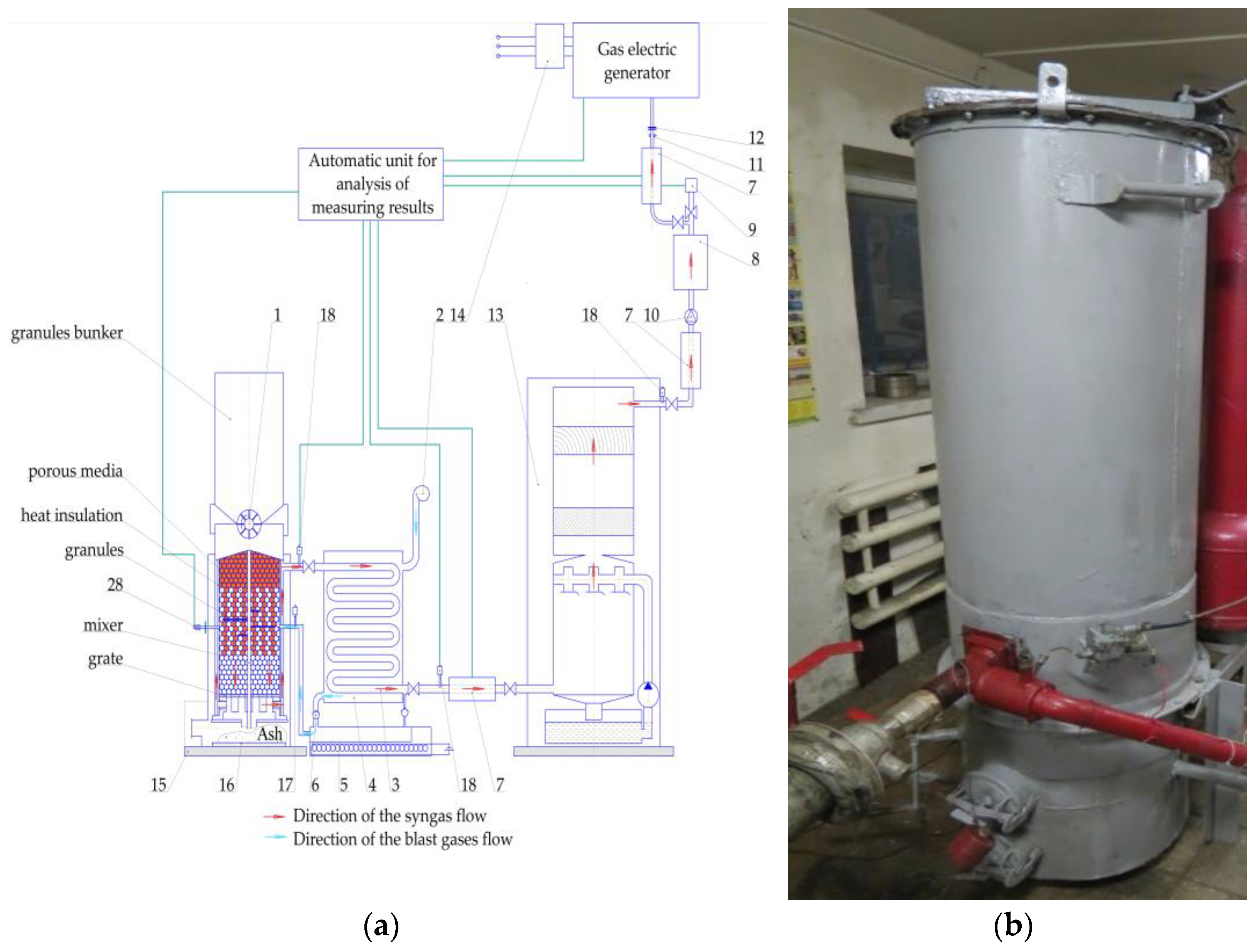
The experiments were held on a pilot plant equipped with a downdraft gasifier. The gasifier capacity was 60–68 m
3/h. Gasifier [
14] was used as the basic design, but the chamber was changed to cylindrical type 350 × 200 × 208 mm (length, ID, and OD, respectively). The material of the gasification chamber was H25N20S2 steel. The block chart (a) and a general view (b) of a pilot gasifier plant are shown in
Figure 1.
All kinds of experiments were carried out in the same reactor.
The hybrid zone (solid fuel and inert porous material) was 300 mm, the inert zone (porous medium) was 250 mm, and the fuel zone (granules) was 480 mm. The height of the hybrid zone is equal to the height of the reaction zone.
The external and internal surfaces of the gasifier were covered with thermal insulation to minimise heat losses. A fibreglass polymer composite (24 mm) was used for the outer side, and a basalt fibre-based material (Paros Fireplace Slab 90 AL1, 4 mm thick) was used for the inner side.
Three different types of inert material were chosen for the experiments: experiment 1—crushed LECA (heat capacity c = 800 J/(kg·°C)); experiment 2—red clay and granite dust mixture composite (heat capacity c = 1000 J/(kg·°C)); experiment 3—grog (chamotte) spheres (heat capacity c = 1200 J/(kg·°C)). The inert material and wheat straw pellets were placed chaotically in a hybrid reaction zone, creating the mixture in the given proportions.
An air–steam flow with a steam content of 40% was used as the gasification agent. The blowing rate varied between 30 and 50 m3/h. The steam-to-biomass ratio ranged from 1.38 to 2.34. A two-stage blower (GHBH 004 34 2R5 3KW) was used for air supply. Steam was formed in an evaporator chamber 5. Air was supplied through the recuperator 4, which was heated to 550 °C and simultaneously cooling the gas to ≈100 °C. The heated air was supplied to the evaporator 5 through the one-way valve 6, where it mixed with the steam. The operation of a two-stage blower and evaporator chamber was coordinated. This makes it possible to control the composition of the air–steam mixture. The recuperator is equipped with gas pipe 3, a one-way valve, and a pipe to drain the condensate from the working zone.
An S-type thermocouple 17 was placed in the reaction zone of the gasification chamber at a point in the tuyere zone. It was used to record the temperature. The temperature was automatically recorded by a PC through the converter. A temperature data error of 50 K is estimated for this type of measurement.
In order to analyse the composition and quality of the syngas at each stage of production, the experimental plant had three gas sampling units, seven installed after the air–gas recuperator (unit 1), the combined purifier (unit 2) and the receiver (unit 3). These samplings were used to determine the CO and H
2 content in the gas, moisture, and mechanical impurities. An Agilent’s 6890N chromatograph was used to determine the H
2 and CO content in the syngas. The requirements of DSTU 3985-1:2001 [
34] were used. The calorific value of the syngas was measured and recorded using a CM6G calorimeter 9. A gas-electric generator was used to utilise the syngas.
Scales 15 were used to weigh the gasifier filled with fuel and inert material. Scales 16 were used to weigh the ash. The stage of pellet burnout was defined by the difference between the scale indications as well as the time of the next pellet reloading to prevent gasifier shutdown (periodic reloading).
The experimental sampling error was estimated to be 10%.
2.3. Experimental Procedure
The research was conducted by a multifactorial experiment. The dependence of the temperature in a reaction zone of a downdraft gasifier (using hybrid filtration combustion) on the air–steam blowing rate, the specific heat capacity of the porous medium, and the volume content of the porous medium in the gasifier reactor were investigated.
This approach differs from classical investigations, where the focus is on the combustion wave and associated temperature profiles.
The investigation of the dependence of the temperature in the reaction zone on the changing factors consisted of such stages. First, the bunker of the gasifier was loaded with a mixture of inert material and pellets. Then, the gasifier was kindled and brought to a stable operating mode. As the pellets burned out, the porous material settled on the grates and filled the space from the grates to the lower boundary of the reaction zone. The reaction zone contained a mixture of inert material and pellets. A mixer was used for the homogeneous distribution of the mixture inside the gasification chamber. The pellets were located in a bunker, a hopper above the gasification chamber, and slowly descended into the reaction zone, mixed with the inert material, and gasified.
Initially, crushed LECA was used as an inert material. Then, a blower was tuned to the appropriate mode, the parameters of a hybrid layer were determined, the temperature in the reaction zone was recorded, and the gas was sampled for chemical analysis. This was then repeated for the red clay and granite dust composites and for the grog spheres.
During the experiments, the air–steam blowing rate, the type of the inert layer, and its characteristics were changed.
The gas sampling unit consisted of a 500 mL glass bulb with two valves. Sampling was made by the free-flow method. The glass bulb was connected to the gas sampling unit 7 and disconnected at the moment when the bulb was filled, not less than 70%. Then, the bulb was connected to the chromatograph. The chemical composition of the gas was determined with a laboratory unit consisting of a two-channel chromatograph “Agilent 6890 N”, a bulb with the carrier gas (argon), a manometer, and a PC for logging. The gas composition was calculated by chromatography according to DSTU 3985-1:2001 [
35].
Factor variation intervals are as follows:
- -
Volume percentage of the inert material in overall volume of the gasification chamber ϕ, vol%;
- -
Heat capacity of the inert material c, J/(kg·°C);
- -
Air–steam supply for gasifying process Vair, m3/h.
Factors encoding: ϕ = X1, Vair = X2, c = X3.
Variation levels of abovementioned factors are given in
Table 1.
According to
Table 1, the lower level of the vol% is 0. The absence of the porous medium is a relative concept, as an insignificant amount of the inert material is always present in the reaction zone. Also, a long period without mixing leads to gravitational settling of the inert material on the grates as the pellets burn out. In some period of time, a clear layering of fuel and inert material is observed. At the same time, remnants of ash and unburned fuel are observed within the inert material, and fuel, in turn, holds some inert material. As the experiment was practical and conducted under real conditions, such deviations are acceptable and do not affect the main course of the experiment.
To reduce the number of experiments and obtain the regression equation, the mathematical method of experiment planning based on the Box–Behnken quadratic plan was used. The planning stage included the following steps: factor encoding, scheduling, randomisation tests, experimental design, testing the reproducibility of the experiments, calculation of the regression coefficients, and assessing the significance of the regression coefficients and the adequacy of the test model. The experiment consisted of 15 tests, each of which was repeated three times [
36].
In order to check the correctness of the research, experiments No. 2, 8, and 14 were carried out under the same conditions. According to the plan of the multifactor experiment, the values of the relative error of the model are lower than 3.24%. This is the case for all experiments. The mean relative error values are lower than 2.78%. Thus, the relative error value is less than 10 %. Such a relative error value is considered acceptable in modelling.
2.4. Gas Mechanical Impurities Analysis
Studies were conducted to determine the level of syngas contamination. The dispersed composition of the dust before and after the combined purifier was determined by the aspiration method using the AFA-VP-20 filter. Prior to analysis, the dust samples were treated with acetone to remove resinous materials and then dried at room temperature (18–22 °C). Dispersity was determined by the method of force analysis and mechanical sieving of fine fractions in the pneumo-classifier. The sieve analysis method was used to determine the dispersity of fractions with a particle size of 43 µm and above.
3. Results and Discussion
As a result of laboratory experiments and statistical calculations, a temperature data array was obtained, which is shown in
Table 2. In
Table 2, the parameter T
med is an arithmetic average temperature value according to the experiment (the experiment was carried out with repetitions). T
med.
com was calculated according to the model and was necessary for its comparison with T
med and for checking the l adequacy of the model.
Regression coefficients: b0 = 1240.34; b1 = 91.5; b2 = 22.83; b3 = −17.73; b12 = −22.33; b13 = 2.57; b23 = 10.31; b11 = −170.26; b22 = −175.79; b33 = −76.42.
The Student test was used to determine the confidence intervals for the regression coefficients. The tabulated value of the Student test was t = 4.3 (number of degrees of freedom of the reproducibility of the experimental variance f1 = 2; significance level—5%).
The Cochrane criterion was used to test the homogeneity of variances. The procedure is reproducible because Gcom = 0.244 < Gtabl (0.05; 15; 2) = 0.4.
The adequacy test of hypotheses of the obtained regression equation was performed by the Fisher criterion. The tabular value of Fisher’s exact test was Ftabl (0.05; f1; f2) = 19.38 (f1 = 2—variance experiment reproducibility degrees of freedom; f2 = 8 variance inadequacy degrees of freedom). The estimated value of this criterion was Fcom = 5.63 (dispersion was Sy2 = 0.5). The hypothesis of the adequacy of the regression equation is confirmed since Fcom = 0.5 < Ftabl = 19.38. The coefficient of determination corrected for the multifactor experiment is R2 = 0.968.
As a result, the regression equation acquired the form:
where
T—the temperature of the reaction zone, °C;
ϕ—volume percentage of inert material in the overall volume of the gasification chamber ϕ, vol%;
c—heat capacity of inert material, J/(kg·°C);
Vair—air–steam supply for gasifying process, m3/h.
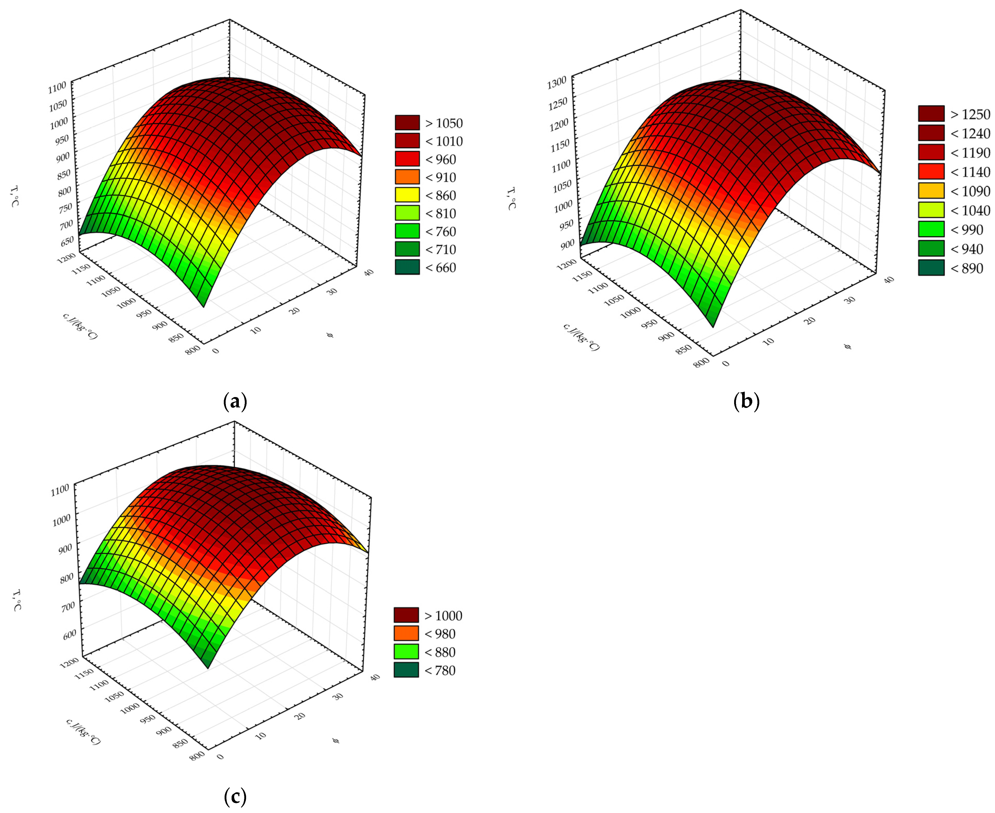
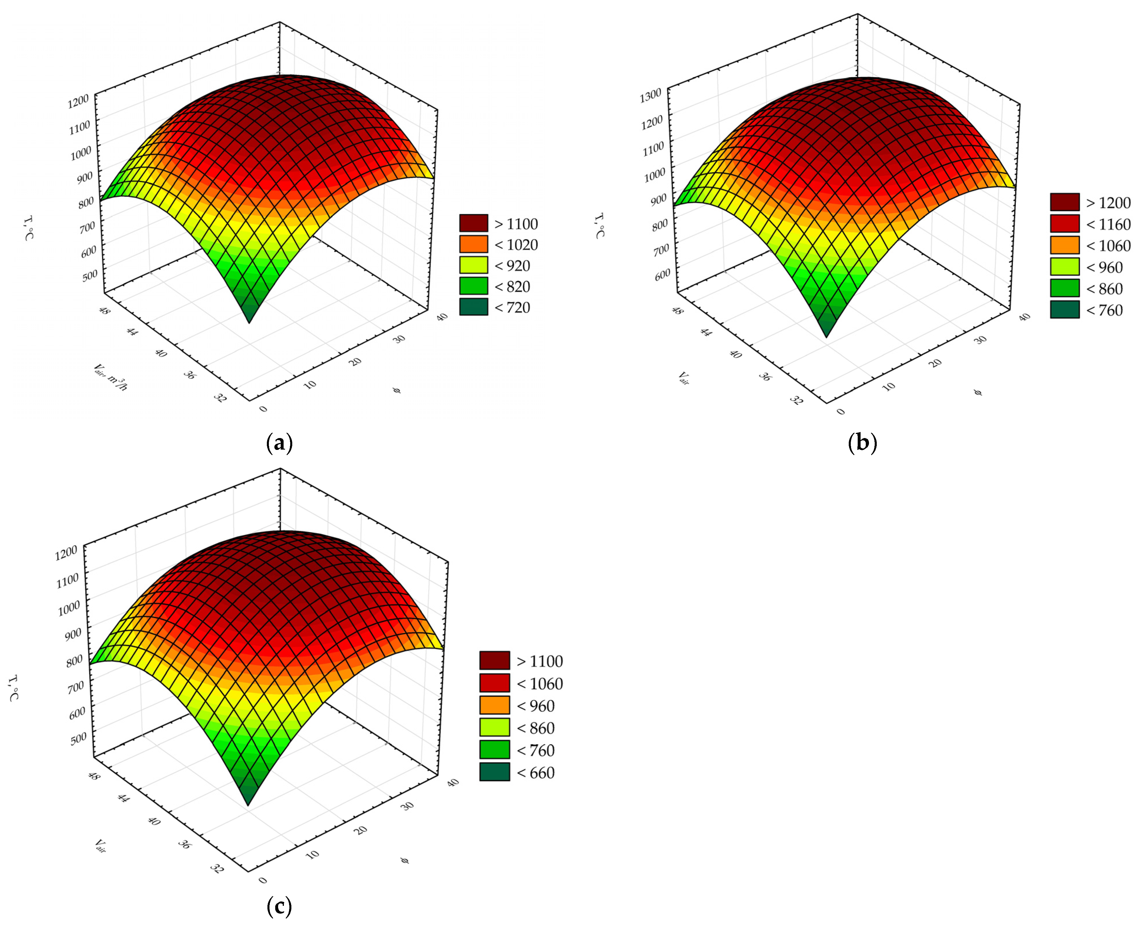
After processing the experimental data in Statistica, graphical dependencies for the optimisation criteria were constructed from the factor variation levels in the form of the second-order response surfaces. Graphical representations of the abovementioned equation are shown in
Figure 2,
Figure 3 and
Figure 4.
According to
Figure 2, the graphical dependence for all vol% (ϕ = 0 vol%, ϕ = 20 vol%, ϕ = 40 vol%) has an accentuated maximum. This maximum defines rational ranges of air–steam blowing and heat capacity variation to achieve maximum reaction zone temperature. The heat capacity is changed by selecting one or another inert material or by mixing them. For blowing rates lower than 35 m
3/h, a characteristic low temperature is observed in the reaction zone due to low oxidant concentration. At this point, the maximum temperature is 750 °C. Raising the blowing rate to 38–45 m
3/h, the temperature in the reaction zone grows to 978–1245 °C (
Figure 2). Further raising of the blowing rate above 45 m
3/h results in blowing out the fuel particles that have not fully reacted, and also, the reaction zone is cooled by the intensive air-stream flow. The highest temperature, ≈1245 °C, was reached at a blowing rate of 42 m
3/h, vol% around 28 vol%, and heat capacity of the inert material 1000 J/(kg·°C). According to the received model, describing the experimental results, in the absence of inert material, the highest possible temperature, 980 °C, could be obtained at a blowing rate of 42 m
3/h. From the obtained data, it was also noted that for the wheat pellets and this particular type of gasifier, a rational range of blowing rate is within 38–45 m
3/h (when there is no inert material). As the content of the inert material in the reaction zone is increased, the blowing rate range shifts to higher values and becomes narrower. At 0 vol%, the blowing rate is 39–45 m
3/h, and at 40 vol%, it is 40–42 m
3/h. Therefore, the use of hybrid filtration combustion requires precise blowing rate control depending on the fuel type and porous medium content to provide high-quality syngas.
As mentioned above, periodic mechanical mixing was used to achieve a homogenous distribution of pellets and inert material in the reaction zone. A drop in temperature within the reaction zone served as a signal to activate the mixing process.
Figure 3 and
Figure 4 show that the highest temperature was reached when the inert material content was 28 vol%. Further increases in the inert material content resulted in less fuel and, consequently, less heat generated from combustion. As a result, the temperature in the reaction zone decreased.
According to
Figure 2,
Figure 3 and
Figure 4, the highest temperatures were observed between 38 and 42 m
3/h when the air–steam blowing rate was increased. Thus, at V = 30 m
3/h, the highest temperatures correspond to an inert material content of 31–32 vol%; at V = 40 m
3/h, it was 29–30 vol%; and at V = 50 m
3/h, it was approximately 23–24 vol%. This could be a result of intensified combustion due to excessive air–steam blowing. Conversely, there is a phenomenon of temperature drop due to heat removal by excessive blowing. Taking into account the amount of heat evacuated from the gasifier with the syngas, the total heat transferred to the inert material decreases. The existence of an optimal temperature range allows us to assume that the fuel consumption in the filtration combustion process is also lower than in the traditional gasification process. In other words, there is an optimum range of blowing rate and porous medium content in the gasification zone where fuel consumption is minimised.
Thus, as proven by numerous investigations [
15,
16,
17,
18,
19,
30,
32], the presence of a porous medium provides a high-temperature mode in the gasifier reaction zone by accumulating heat and preventing it from being evacuated with the syngas. This, in turn, promotes higher CO and H
2 contents in the syngas and reduces its contamination.
The dependence of the H
2 and CO content in the syngas on the blowing rate for different porous medium contents, as obtained from experiments, is shown in
Figure 5.
As expected, the concentration of H
2 in the gas increased as the blowing rate increased (
Figure 5). This occurred because there was more hydrogen available in the reactants due to the higher blowing rates. The growth in H
2 concentration continued until the blowing rate reached 42–44 m
3/h; beyond this point, the H
2 content began to decrease. The rate of decrease in H
2 concentration was lower than the rate of decrease in reaction zone temperature e (
Figure 2,
Figure 3 and
Figure 4). The decrease in hydrogen concentration was attributed to the intensive evacuation of unreacted fuel from the reaction zone, together with its cooling due to excessive blowing.
When using porous medium combustion, the temperature, as well as the concentrations of H
2 and CO, increase due to the higher filtration velocity. This increase is due to the reduced residence time of the filtered reactants. Such behavior is typical for all values of the volume percentage of an inert porous medium in the reaction zone (ϕ = 0; 20 and 40 vol%). In works [
16,
24], it has been demonstrated that the addition of steam and the increase of the filtration velocity are accompanied by a growth of the H
2 concentration.
Comparing the data in
Figure 5, the highest hydrogen content corresponds to the inert material content of 40 vol%, which is close to the results presented in [
26]. When considering the concentration growth during the gasification of wheat pellets without inert material, the dependence on the blowing rate exhibits a similar pattern to the dependencies shown in [
14].
The addition of steam (
Figure 5) also promoted the growth of CO production. The highest CO concentration was achieved when the volume of inert material was 20 vol%, in contrast to hydrogen, which was highest when the inert material accounted for 40 vol%. The presence of a minimal amount of inert material at a blowing rate of 44 m
3/h enhances the intensification of CO generation reactions and reduces the content of CO
2 and H
2.
The results presented here are partly consistent with the findings of Toledo et al. [
29], who investigated hybrid filtration combustion of biomass. In their study of hybrid filtration combustion with wheat straw, maximum H
2 production occurred at a lower temperature compared to ours (around 700 °C, however, at the same biomass-to-inert material ratio).
The calorific value of the syngas was measured, as well as the level of gas contamination. During the air–steam gasification of wheat pellets without the porous medium, the calorific value of the gas was 10.2 MJ/m3 at a blowing rate of 42–44 m3/h. Under the same conditions, but with a porous medium content of 20 vol% and a heat capacity of 1000 J/(kg·°C), the calorific value increased to 11.3 MJ/m3, and with a porous medium content of 40 vol%, it reached 12.6 MJ/m3.
In our case, the use of 40% vol of the porous medium allowed for a 33% increase in the H2 content in the syngas compared to normal air–steam gasification of wheat pellets. The s calorific value of the gas increased by almost 22%.
One promising wheat-based fuel gasification technology is the development of slagless gasification. Compared to the traditional gasification of wheat-based fuels in a downdraft gasifier, the presence of air–steam blowing and an inert porous medium minimises the negative phenomenon of ash agglomeration.
Glass-like deposits were observed on inert materials and on the grates but in much smaller quantities. However, when the laboratory results are scaled up to an industrial scale, the advantages and disadvantages of this technology could also be scaled up accordingly. The positive influence of using air–steam gasification to prevent the phenomenon of slag agglomeration has also been demonstrated in previous works [
37,
38].
In the experiment, a zero level of inert medium content was introduced for comparison with classical gasification. The surfaces in
Figure 2,
Figure 3 and
Figure 4 illustrate that the temperature in the reaction zone in the case of filtration combustion is significantly higher than in the case of classical gasification under the same technical and technological conditions. This higher temperature leads to a higher content of combustible components in the syngas.
The gas exiting the gasifier had a dust contamination level of 21 mg/m3. This was primarily due to the contribution of the agglomeration phenomenon resulting from mechanically incomplete fuel combustion and the entrainment of fuel particles with the syngas. It is impossible to completely remove the dust from the gas by technological means.
The percentage composition of the dust dispersion i was as follows: 48% at particle size of 45–50 µm; 16% at 35–45 µm; 9% at 25–35 µm; 8% at 18–25 µm; 4% at 8–18 µm; 9% at 4–8 µm; 6% below 4 µm. The dust was 93% carbonaceous particles.
Based on the results of this work, it can be concluded that the technology of biomass filtration combustion in a downdraft gasifier is a promising method for the production of high calorific value syngas with a high content of H2 and CO. Compared to classical gasification, filtration combustion offers several significant advantages, including uniform heat distribution throughout the gasifier volume, higher temperatures in the reaction zone due to inert porous media, shorter biomass residence time in the reactor, a wider power range for gas production compared to air and steam–air gasification, and high carbon conversion. The resulting syngas has a high calorific value in the range of 12 to 14 MJ/m3, with low mechanical impurity content.
However, the technology of biomass filtration combustion has some drawbacks that limit its widespread application, including the need for a more complex gasifier design, accurate calculation of the percentage of inert material in the reaction zone, control of the gasification agent rate, and the need for consistent management of the required filtration rate.
The results of this study suggest that the use of agricultural plant biomass in hybrid filtration combustion with the air–steam agent has the potential to enhance H2 and CO production, but further research is needed to optimise syngas production conditions. This includes the development of a mathematical model that can generalise the experimental results. In addition, studies aimed at identifying the locally produced products in the reaction zone, their volumetric content, and conversion rates could provide a more comprehensive understanding of the phenomena.


 ,
, 


