Article

Polymorphic Virtual Synchronous Generator: An Advanced Controller for Smart Inverters

1
Univ. Grenoble Alpes, Grenoble INP, CNRS, G2ELab, 38000 Grenoble, France
2
Univ. Grenoble Alpes, Grenoble INP, CNRS, GIPSA-Lab, 38000 Grenoble, France
3
Power Conversion Department, Schneider Electric Industries, 38000 Grenoble, France
*
Author to whom correspondence should be addressed.
Energies 2023, 16(20), 7075; https://doi.org/10.3390/en16207075
Submission received: 10 August 2023 / Revised: 23 September 2023 / Accepted: 10 October 2023 / Published: 13 October 2023
(This article belongs to the Special Issue Progress in Design and Control of Power Converters)

Abstract

:
Virtual synchronous generators (VSGs) are one of the most relevant solutions to integrate renewable energy in weak grids and microgrids. They indeed provide inverters characteristics of rotating machines (inertia for instance) that are useful for stabilizing the system, notably in the context of the high variability of the production. Thanks to the virtual characteristics of the VSG, the virtual parameters of the emulated synchronous machine can be optimally adapted online as a function of the electric environment of the inverter. We call that inverter’s control a polymorphic VSG. The online adaptation of the critical control parameters of the VSG helps reduce the risk of deterioration of the inverter’s constituents that might be induced by harsh events (frequent in weak grids) but, more importantly, improves the robustness of the system. In this paper, four implementations of a polymorphic VSG controller are compared on a simple microgrid study case to a complete VSG model. For the test, polymorphic VSGs have to minimize frequency and voltage oscillations while withstanding short circuits, which is typically a requirement for units in this context. One of the controls is based on recurrent optimization over a prediction time horizon, and two sub-optimal ones target practical implementation in industrial inverters with limited computational power. Results show a clear reduction in incidents in the microgrid thanks to the controllers. The error reduction with the complete polymorphic VSG is up to 100% for the voltage, 32% for the currents, and 79% for the duty ratio. Those values are decreased by 30 to 50% with the sub-optimal controllers but for a reduction in the computational burden of more than 97%. Recommendations are proposed for the development of an auto-adaptive polymorphic VSG from a high technology-readiness-level perspective, i.e., targeting a compromise between error reduction and computational burden.

1. Introduction

With the necessary transition to resources that emit fewer greenhouse gases, the diesel generator sets (Gensets) based on synchronous machines (SMs), which constitute traditional distributed energy resources (DERs) supplying isolated microgrids, are being gradually supplanted by renewable energy sources (RESs). However, these new power inverter-based generators increase stability issues in microgrids and more generally in weak grids. Indeed, the insertion of RESs decreases grids’ global inertia and their capacity to remain stable after a harsh load impact [1]. One promising solution to tackle the aforementioned issues and also to allow a higher integration of RESs is the use of advanced inverter controls, for instance, based on the virtual synchronous generator (VSG) concept [2]. Those devices (partly) emulate the behavior of SMs, which are well-known components, thus easing their integration.
VSG inverters were initially mostly considered for their advantages when integrated into microgrids [3,4,5]. The virtual parameters of the VSG can be chosen offline, depending on the configuration of the microgrid, or even during operations, when the microgrid faces harsh events, for instance relying on model predictive control [6]. In that case, we are talking about a self-tuning or auto-adaptive VSG controller [7,8,9]. Thanks to a control based on virtual inertia, the self-tuning VSG inverter is used as a grid-forming unit that enables mitigating the risks of voltage or frequency oscillations during harsh events, such as short-circuits or islanding transitions [10,11]. Recently, in addition to the SM inertia, the online adaptation of the damping coefficient, using the swing equation, has also been considered to improve VSG performance [12,13]. The SM virtual parameters are rarely considered in such a self-tuning implementation of VSGs. In [14], for instance, only one parameter of the SM model is controlled.
Self-tuning VSGs, notably able to automatically adapt most if not all of their virtual parameters, are a relevant solution to increase the range of control possibilities [15], notable for improving microgrid stability [16] or other critical parameters, even with relatively simple solutions in mind [17]. This needs to be conducted without deterioration of the inverter’s constituent, which means avoiding excessive changes in the main parameters of the inverter’s control. We consider such a possibility, referred to as polymorphic VSGs in our research. The polymorphic VSG is developed in an industrial context, where standardization constraints have to be fulfilled. As there is no standard for VSGs, requirements for Gensets are considered, notably the capacity to ride through short-circuits.
The main contribution of this research is, using a complete VSG model from previous research, to identify the most important control parameters (five in our case) that ensure a stable operation of the inverter, i.e., minimize frequency or voltage oscillation but also go through a typical set of short-circuits. To that aim, an online optimization process is implemented that will automatically change the selected main parameters as a function of the electric environment of the inverter (with a step every time-step). The polymorphic VSG is tested over a range of typical scenarios that was adapted from GenSets standards, as we cannot find one directly for VSGs installed in microgrids. Results are obtained in a representative simulation environment that shows the technical compromise between a heavy but precise polymorphic controller or a slightly sub-optimal one that will still allow obtaining results that are close enough from an optimal theoretical baseline.
This paper is organized as follows: First, the concept of polymorphic VSGs is described and analytically detailed in Section 2. It proposes a VSG with self-tuning of all the parameters of the virtual SM. In Section 3, advanced solutions are investigated to make the implementation of the polymorphic control possible. Section 4 proposes a comparison between those solutions and discusses their advantages and disadvantages on a standardized test. After discussing results, Section 6 concludes with further work.

2. Analytic Model of the Polymorphic VSG

Regular VSG inverters could increase the risk of instability of the overall system through their control and current and/or voltage limits, in addition to possibly deteriorating the constituents of the inverter directly. As a response, the polymorphic VSG optimizes the virtual SM parameters to limit or, at best, avert the inverter’s deterioration in case of current or voltage overshoot and during the inverter’s duty ratio saturation.

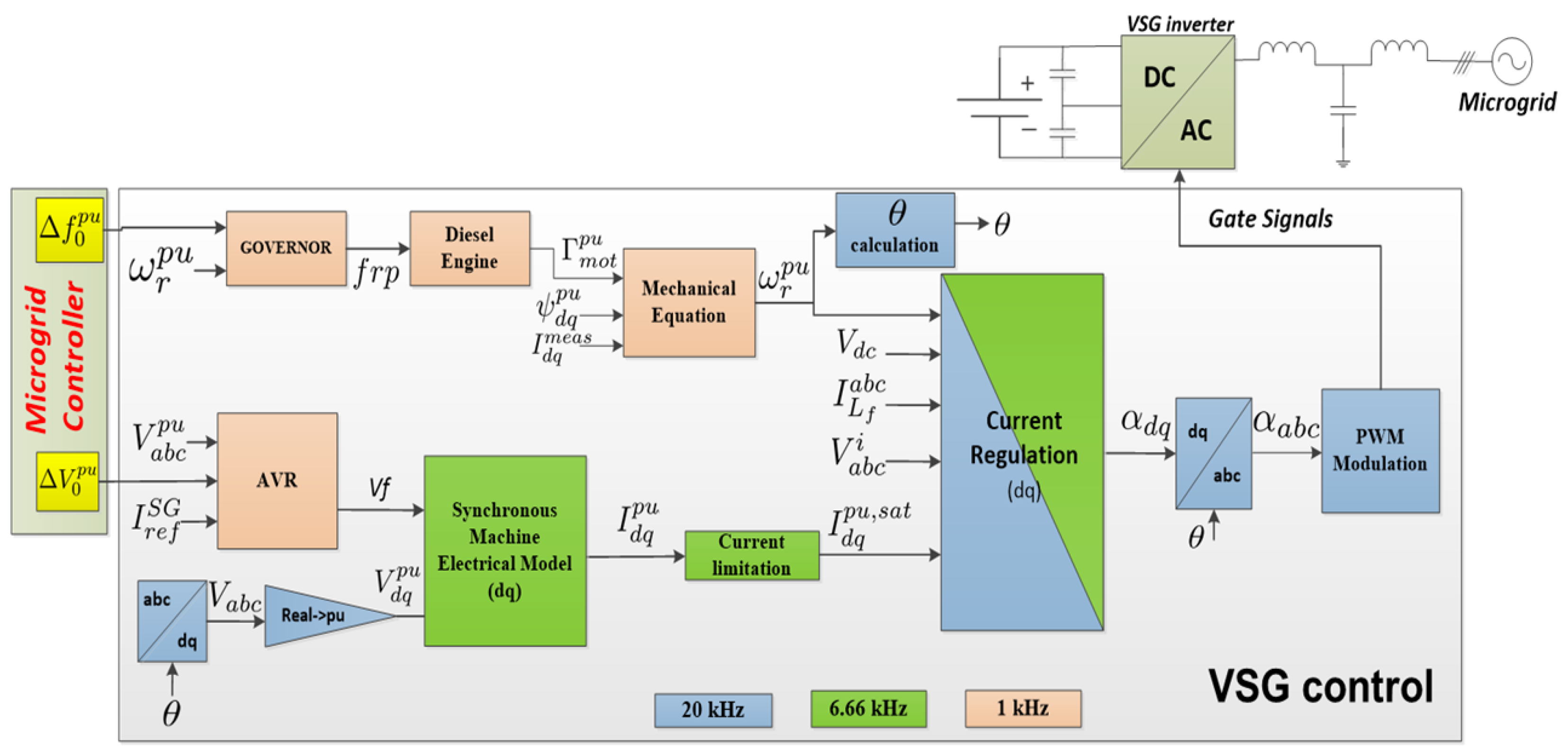
2.1. A Polymorphic VSG

The proposed polymorphic controller is based on a predictive control design [18]. At each decision time, the next steps are followed:
  • Given the current state of the system, an optimal sequence of parameters is obtained by formulating a constrained optimization problem whose cost function and constraint penalties on the satisfaction and quality of the regulation are expressed in Section 2.2;
  • The optimal sequence is found using a nonlinear programming solver since the optimization of the parameters is not linear;
  • The corresponding values of the VSG parameters are assigned to the system over the sampling period;
  • At the beginning of the next sampling period, the new optimization problem is defined given the new value of the state vector. This process continues indefinitely leading to state feedback.
The controlled outputs of the polymorphic VSG are the SM parameters over the next prediction horizon. The polymorphic VSG is based on the “reduced SM model” that is analytically described in [19]. It is a simplified enough SM model that has been shown as the most adapted one for VSG-based inverters requested to pass Genset standards. As the SM model is entirely virtual, it is possible to consider any values for the parameters, notably the L d and L q reactance. The virtual model could then vary from a salient machine to a non-salient one from one time horizon to the other as a function of external conditions and optimization results.
The reference virtual SM parameters set p r e f and the candidate one p k at a decision time k, are expressed in (1), with p r e f M 5 , 1 and p k M 5 , 1 .
p r e f = L r e f d L r e f d L r e f q R s , r e f T d 0 , r e f and p k = L k d L k d L k q R s , k T d 0 , k .

2.2. Analytical Model

To express the optimization problem’s constraints and its cost function, a state-space VSG controller model detailed in [20] is used. It relies on a switched-level model of the inverter. The extended system includes an observer, in which the controlled input is the increment Δ U . Its schematic representation is proposed in Figure 1. The predicted states are used in the complete controller to minimize the impact of monitoring errors.
The current controller is a linear quadratic regulator incorporating an integrator and the state observer. The complete VSG control is presented in Figure 2, which was implemented in a digital signal processor (DSP) quite directly because the controller is discrete. The development and simulation tool is Matlab/Simulink™ using the “Embedded Coder” toolbox of Mathworks™. The “Code Composer Studio” toolkit is used for the implementation in the inverter’s DSP (a TMS320F28335, Texas Instrument™, Dallas, TX, USA).

2.2.1. State-Space Model

The discrete state-space VSG model in dq and p.u. used in the polymorphic VSG control is expressed in (2).
X ^ Δ + = A Δ s ( p k ) × X ^ Δ + B Δ s ( p k ) × Y Y ^ Δ = C Δ s ( p k ) × X ^ Δ + D Δ s ( p k ) × Y with Y m e a s = i d i q ψ d ψ q ψ f d i L d i L q e d e q e f d Δ α d Δ α X Δ = ψ d ψ q ψ f d i L d i L q e d e q i g d i g q ε I n t d ε I n t q α d α q e f d V g d V g q ,
where X Δ is the state vector. The measured outputs Y m e a s and the controller’s reference values ε * are presented as Y = Y m e a s ε * . The system’s matrices are expressed as A Δ s ( p k ) , B Δ s ( p k ) , C Δ s ( p k ) , and D Δ s ( p k ) . The fluxes of the virtual SM model are ψ d , ψ q , and ψ f d . The excitation voltage is e f d d , and the reference currents of the SM model i d and i q are based on the fluxes. The currents and voltage outputs of the inverter, before the LCL filter, are i L d and i L q , e d , and e q , respectively. The currents and voltages of the grid, after the LCL filter of the inverter, are i g d and i g q , V g d and V g q . The inverter duty ratios are α d and α q , and Δ α d and Δ α are additional outputs regulated by the controller. The integration states of the controller ε I n t d and ε I n t d are added to the regulation of the inverter system [20].
Thanks to the state-space model defined in (2), the predicted profiles of the state vector X ^ Δ 0 are calculated in dq and p.u. for each time m [ 0 ; N ] , with N being the prediction time horizon. The optimization problem is defined for a given state vector X ^ Δ 0 in which the profile of the SM virtual parameters is considered to be constant over the prediction time horizon. As the controller model expressed in (2) is discrete, each step of the prediction time horizon is equal to the sampling time of the controller model to ensure its convergence. Hence, N steps of the prediction time horizon correspond to N times the model (2) sampling times regarding the computational burden. The sampling time of the polymorphic control is different from the one defined in (2). To ensure the model’s stability, its sampling time defines two consecutive steps of the prediction horizon. Also, the first values of the parameter vector are applied before the first optimization problem is set and solved.

2.2.2. Optimization

The main objective of the polymorphic control is to minimize over-currents, over-voltages, and/or the saturation of the inverter duty ratio. Hence, the considered predicted profiles are based on the following variables:
  • The inverter output currents, i L d and i L q ;
  • The inverter output voltages, e d and e q ;
  • The inverter duty ratio, α d and α q .
The constraints of the optimal control problem, defined for each sampling time, are the voltage and current overshoots, noted V E and V I , and the saturation of inverter duty ratio, V α . All are functions of m, X ^ Δ 0 , and p k . Hence, considering the state vector input X ^ Δ 0 at a decision time k, for an instant m included in the prediction time horizon [ 0 ; N ] with a set of SM virtual parameters p k , the voltage and current overshoots and the inverter duty ratio saturation are determined as
V E = e d ( m , X ^ Δ 0 , p k ) 2 + e q ( m , X ^ Δ 0 , p k ) 2 e m a x
V I = i L d ( m , X ^ Δ 0 , p k ) 2 + i L q ( m , X ^ Δ 0 , p k ) 2 i m a x
V α = α d ( m , X ^ Δ 0 , p k ) 2 + α q ( m , X ^ Δ 0 , p k ) 2 α m a x .
The maximum admissible magnitude values in voltage, current, and duty ratio at the inverter outputs are noted as e m a x , i m a x , and α m a x , respectively.
Consequently, the voltage and current overshoots and saturation during the prediction time horizon [ 0 ; N ] can be written as follows:
V E ( X ^ Δ 0 , p k ) = V E ( 0 , X ^ Δ 0 , p k ) . . . V E ( m , X ^ Δ 0 , p k ) . . . V E ( N , X ^ Δ 0 , p k )
V I ( X ^ Δ 0 , p k ) = V I ( 0 , X ^ Δ 0 , p k ) . . . V I ( m , X ^ Δ 0 , p k ) . . . V I ( N , X ^ Δ 0 , p k )
V α ( X ^ Δ 0 , p k ) = V α ( 0 , X ^ Δ 0 , p k ) . . . V α ( m , X ^ Δ 0 , p k ) . . . V α ( N , X ^ Δ 0 , p k ) .
The analytic representation of the voltage and current overshoots, as well as the inverter duty ratio saturation, are V E ( X ^ Δ 0 , p k ) M N , 1 , V I ( X ^ Δ 0 , p k ) M N , 1 and V α ( X ^ Δ 0 , p k ) M N , 1 , respectively. Hence, the solution to the optimization problem of the polymorphic control is the new set of SM virtual parameters p k that enables V E ( X ^ Δ 0 , p k ) , V I ( X ^ Δ 0 , p k ) , and V α ( X ^ Δ 0 , p k ) to be lower than zero during the entire prediction time horizon [ 0 ; N ] .
To guarantee a bounded optimal solution, the set of admissible parameters p k is limited to a ranged region of possibilities. More precisely, the domain of possible values of the parameters p k , denoted J , is defined in (9), where V l i m 1 is a design parameter.
p k J = p r e f / V l i m ; p r e f × V l i m .
To avoid improper SM virtual parameter oscillations, the variation between two successive values of SM virtual parameters is also considered in the cost function. Moreover, the distance to the reference values of the parameters is also penalized to restrict the variation of the parameters to only cases where this variation brings sensitive improvement to the system’s behavior. A slack variables vector ϵ is added to implement a soft constraint guaranteeing that the problem always admits a solution. This is mandatory for practical, real-life implementation of the procedure. When optimization is necessary due to a violation of the predicted variable during the prediction horizon, to reduce the number of needed iterations in the optimization step, a warm start initial guess is used. Namely, the value of the parameter at the previous decision time k 1 . This is used as the starting point of the optimization problem at the decision time k.
The optimization problem implemented in the polymorphic control is proposed in (10), where i denotes the index of the SM virtual parameters, and β and μ represent weights that were adjusted so that the optimization problem reaches correctly an acceptable solution. The final value of these parameters is provided in Table 1.
min p k J , ϵ O 3 N , 1 i = 1 5 p r e f ( i ) p k ( i ) p r e f ( i ) 2 + β i = 1 5 p k 1 ( i ) p k ( i ) p r e f ( i ) 2 + μ l = 1 3 N ϵ ( l ) 2 under V E ( X ^ Δ 0 , p k ) V I ( X ^ Δ 0 , p k ) V α ( X ^ Δ 0 , p k ) ϵ O 3 N , 1 .
The optimization problem is solved using the nonlinear programming integrated framework CasADi with the solver option nlpsol/IPOPT [21]. If the optimization problem (10) is infeasible for some scenarios, which should not be the case due to the use of the slack variables vector ϵ , no decision is made on the parameter values. In this case, there is indeed no change compared to the previous time step. The parameter values are refreshed at each decision time k.
Figure 3 summarizes the inputs of the polymorphic control, namely the state-space vector inputs X ^ Δ 0 , the solution applied at the previous time step of the optimization problem (at the decision time k 1 ) p k 1 , and the slack variable ϵ . The outputs of the polymorphic control are the solution of the optimization problem p k that will be applied to the SM model and a new ϵ .
The nominal values of the SM model and the polymorphic VSG control main parameters are proposed in Table 1. In the presented simulations, the polymorphic VSG control is operated at a frequency of 1 kHz with a prediction time horizon of 1 ms, with N = 20 .

2.3. The Behavior of the Polymorphic VSG

In this section, an illustration of the behavior of the polymorphic VSG is presented and compared to a more traditional implementation of a VSG, used as a reference. The reference VSG presents the same SM model as the polymorphic VSG but its SM virtual parameters are fixed to p r e f , i.e., the nominal values presented in Table 1.
For the comparison, both the reference and the polymorphic VSG controls use the same SM model, namely the “reduced SM model” that can be found in [19]. This section examines the behavior of the controlled polymorphic VSG unit during a short-circuit. This test is indeed one of the most demanding stress tests the inverters could have to overcome in standards yet to come.
Figure 4 shows the output voltages during a three-phase short-circuit for both the reference and the polymorphic VSG controllers. The presented results were obtained with a simulation using Matlab/Simulink™, but were also validated with real-time experimentation. The continuous horizontal black lines represent the voltage limits that are considered to avoid the deterioration of the inverter’s constituents, though saturating the inverter’s voltage means that there is a risk of instability for the microgrid. It can be noted that thanks to the polymorphic control, the output voltage limits are not reached by the polymorphic VSG, thus minimizing the risk for the inverter.
The voltage oscillations that are visible for the polymorphic VSG in Figure 4 are due to the modifications of the parameters. This is highlighted in Figure 5, which proposes the evolution of the set of SM virtual parameters, L k d , L k d , and L k q . Those parameters are modified online so that the inverter output voltages avoid reaching the predefined limits. Note that R s , k and T d 0 , k , the two other SM virtual parameters, are not shown in Figure 5 as they remain equal to their reference values during this test.
There is a correspondence between the action on the parameters and the evolution of the electric quantities in the case of the polymorphic VSG, leading to a stable operation (i.e., within limits), which constitutes an advantage compared to the reference VSG. Only a short-circuit test is proposed here, but the polymorphic controller is also tested on 100% variation of resistive, inductive, and capacitive loads as well as black start with success.
It is thus worth creating an industrial version of the polymorphic VSG, even if this version should be sub-optimal, as the DSP of industrial inverters may not be able to provide sufficient computational power to host the polymorphic controller. Therefore, the next section investigates solutions permitting the development of an online polymorphic VSG suitable for more restrictive computational power, based on actual microprocessors available in current commercial inverters.

3. Integrating the Polymorphic VSG Controller in Industrial Inverters

When looking for solutions enabling the integration of the polymorphic VSG in industrial inverters, the problem mainly lies in the computation time and the memory burden. They need to be contained at the price of a drop in performance.

3.1. Regression Models for Optimal Solutions

The first idea is to solve offline a set of open-loop optimization problems that are encountered during an extensive set of closed-loop simulations and to use the resulting data as a training set for a machine-learning regression model [22]. The objective is to spare the computational time spent in the optimization step to reach an optimal solution by providing in advance a predefined set of optimal solutions to the controller. In this approach, the offline optimal values are used as labels while the previously measured outputs are used as vectors of features.
In our case, as it is shown in Table 2, only the parameters L k d , L k d , and L k q have been considered for the regression since the parameters R s , k and T d 0 , k remained constant during the multiples tests scenarios and simulations, notably discussed in Section 4.1. Each of the three parameters, L k d , L k d , and L k q , have a dedicated regression model. Table 2 indeed provides the total number of changes of value of those five key parameters and also the number of iterations in the simulation where the values were different (i.e., there was an automatic change of parameter from one time step to the next). The ratio of both indicators provides a good indication of the importance of the considered parameter regarding the stable operation of the controlled VSG.
The regression models have different input and output vectors than the polymorphic controller considering that only the modified parameters are kept for the regression. So, for each simulation and decision time, the relevant inputs of the polymorphic control have been recovered and accumulated in the same vector X ^ Δ 0 with the previous decision time set of parameters p k 1 . This constitutes a total of 21 inputs. The slack variables ϵ are not considered as inputs of the regression model.
To build and validate the regression model before its implementation in the polymorphic VSG, 50% of the scenario data is used to learn (as a training set) and 50% is dedicated to the model validation.
Different regression methods have been tested (notably kernel ridge, decision tree, and nearest neighbor). The set of values was also quantified so that classification methods can be used (support vector machine in our case). Moreover, for each regression model, two configurations have been applied: a regression on raw data or after a standardization (ST) and a principal component analysis (PCA).
The methodology used to determine the regression model as a function of the data, raw or after an ST and PCA, for each of the three parameters L k d , L k d , and L k q is described below:
  • Recuperation of 50% of the polymorphic VSG data during the stage presented in Section 4.1;
  • Removing the data if the parameter is equal to the reference value;
  • Permutation and mix of the data vector to remove any temporal relationship;
    • Regression model based on the raw data depending on the selected regression algorithm;
    • Or regression model with ST and PCA:
      (a)
      Determination of the ST coefficients: centering means and variances;
      (b)
      Determination of the PCA matrices;
      (c)
      Determination of the regression model based on the ST and PCA inputs depending on the selected regression algorithm;
  • Then, the regression models are validated:
    (a)
    Validation on the other half of the data vector;
    (b)
    Integration on the VSG controller and simulation of the scenarios defined in Section 4.1.

3.2. Finite Set of Admissible Parameters

In addition to the implementation of different regression models, with or without ST and PCA, another solution to implement the polymorphic VSG concept in an industrial inverter is based on the online determination of the best parameter combinations. Those are limited to a finite set of admissible possibilities, which permits avoiding the realization of over-voltage, over-current, or saturation.
The idea is that what does matter is not the fine-tuning of the parameters but whether they decrease, increase, or remain constant. Hence, at each decision time, only a limited and discrete set of parameter combinations is available, and the best solution is selected. More precisely, the following admissible domain K of nine values for the parameter p k is considered:
K = L m i n d L r e f d L m a x d × L d L r e f d L m a x d × L m i n q L r e f q L m a x q × { R s , r e f } × { T d 0 , r e f } .
Hence, the updated version of the optimization problem (10) is expressed in (12).
m i n p k K i = 1 3 p r e f ( i ) p k ( i ) p r e f ( i ) 2 + β i = 1 3 p k 1 ( i ) p k ( i ) p r e f ( i ) 2 with : V E ( m , X ^ Δ 0 , p k ) V I ( m , X ^ Δ 0 , p k ) V α ( m , X ^ Δ 0 , p k ) O 3 N , 1 ,
This is solved by simple enumeration, which needs nine simulations of the system over the prediction time horizon. This presents no problems for the inverter’s controller.

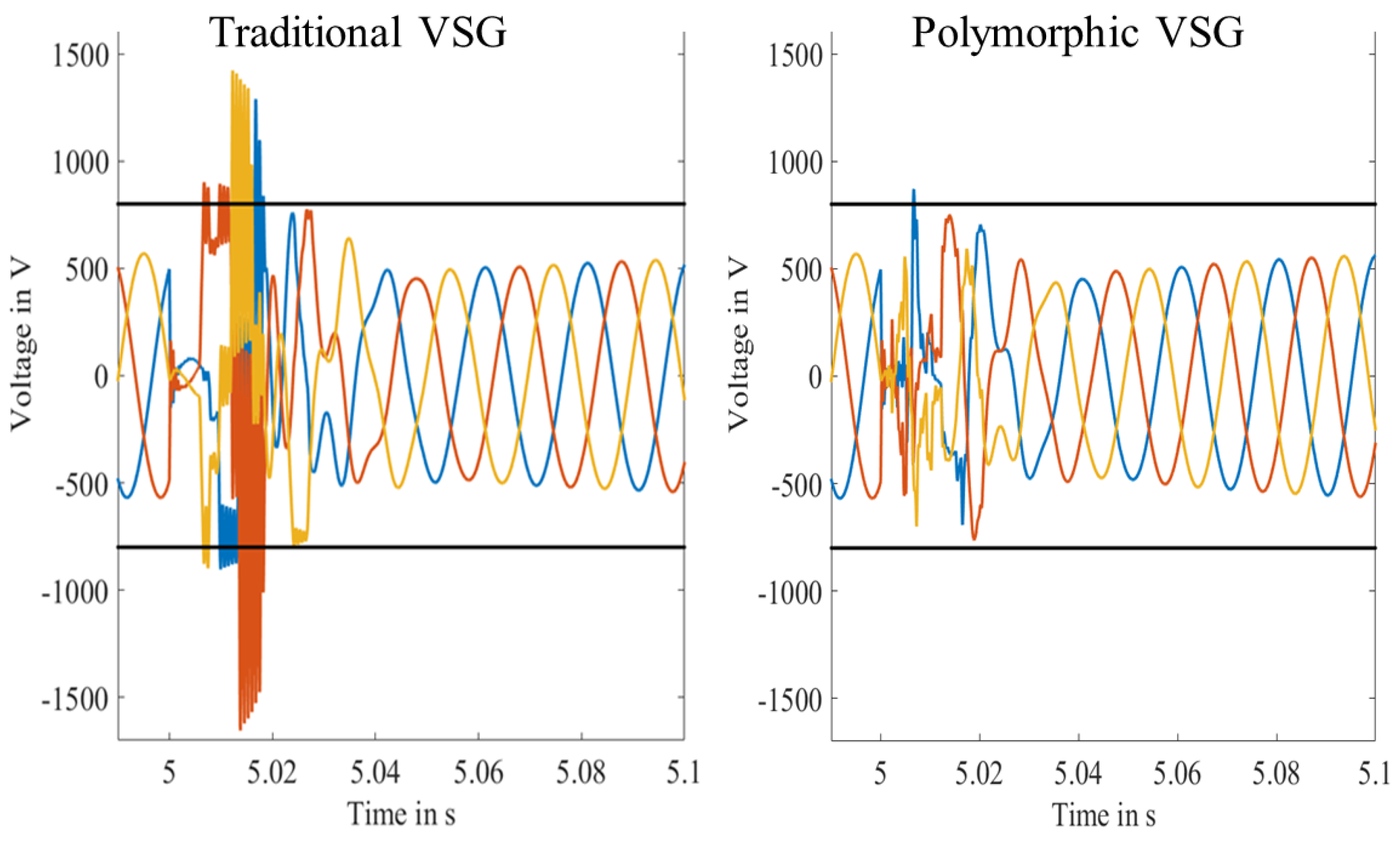
4. Comparison with Reference Solution

This section provides a wider assessment of the ability of the polymorphic VSG and compares four solutions with the reference VSG to avoid or minimize the inverter deterioration due to over-voltage, over-current, or saturation during harsh events that might occur in a real microgrid.
The four solutions are the polymorphic controller with dynamic optimization (presented in Section 2) and the two adapted solutions presented in Section 3, with two flavors of regression methods (with or without ST and PCA). The results of the regression method presented in this paper rely on the kernel ridge model, but other regression models have been tested with similar results.
The inverter used to implement the polymorphic VSG is a Schneider Electric Conext CL 25 of 25 kVA for a voltage of 230 V RMS at a frequency of 50 Hz. The inverter limits on the current, the voltage, and the duty ratio are considered to determine the number of constraint violations for the implementation in the polymorphic VSG control. An incident is triggered each time the magnitude of the studied measure is equal to or exceeds its limit value, thus generating a refresh of the virtual parameters of the SM. The considered limits are:
  • Maximum duty ratio α m a x = 1 p.u.;
  • Maximum voltage magnitude e m a x = 750 V;
  • Maximum current magnitude i m a x = 60 A.

4.1. Scenarios Definition

Two categories of harsh events are conducted for this work:

4.1.1. Short-Circuits

Phase-neutral, phase–phase, and three-phase short-circuits are tested. As short-time short-circuits are more demanding, the duration of the incident is set to 20 ms. In this case, the VSG is the only power source of the considered microgrid, and the short-circuit is applied directly at the output of the inverter.

4.1.2. Harsh Load Variations

An inverter, with the polymorphic or the reference controller, is connected to a load, thus constituting a simple microgrid, and 100% load variations (increase or decrease) are introduced to destabilize the microgrid and affect the VSG-based inverter (resistive, inductive, and capacitive).

4.2. Feasibility

The practical feasibility of the implementation of the polymorphic VSG controller for the proposed solutions, considering the computational limitations of industrial inverters, is evaluated through the execution time on a computer with the following configuration: Intel CoreTM i7-6820HQ, CPU: 2.7 GHz, RAM: 16 Go.
The time necessary to solve a single optimization problem is noted as the block unit time and is based on the sampling frequency of the polymorphic controller, which is 1 kHz. Once it is determined, it is possible to calculate the remaining additional time on the CPU card in comparison with the maximal period. Hence, the additional CPU load on the control card is based on (13), considering the maximal period of the polymorphic controller equal to 1 ms.
C P U a d d = Block unit time Maximal period of the polymorphic controller .

4.3. Results and Comparison

The evolution of the parameters of the SM model implemented in the VSG is proposed in Table 3. The variation in the number of incidents encountered by the polymorphic VSG is compared to the one obtained with the reference VSG. Hence, a negative symbol means that the number of incidents has reduced compared to the reference VSG (with fixed SM parameters).
The polymorphic control addresses the over-voltage risk, which is an advantage for both the inverter and the load connected to the microgrid. The fact that the risk of saturation of the inverter is reduced by more than 70% (for the dynamic optimization) is a major advantage since it means that the risk of instability after saturating the duty ratio is significantly reduced as well.
The polymorphic VSG is less efficient in reducing the risk of reaching the maximal current in the three implementations. Indeed, the output inverter currents are linked to the load characteristics, so as mainly short-circuits have been tested, it is expected that the maximal current is reached even by the polymorphic VSG. In this context, a fault could be detected in real life, possibly with a decrease in selectivity and/or an adaptation of the existing protections. This is unchanged compared to any other inverted-based generator controllers.
Table 4 shows the time simulation of the three investigated solutions, the block unit time, and the additional CPU load remaining on the control card. The regression models are the fastest solutions with only 1% overload compared to the traditional VSG. The enumeration-based solution presents an overhead of about 4%, which makes it also a relevant solution.
The bloc unit time to determine one set of optimal SM virtual parameters for the polymorphic VSG (to solve once in the open-loop optimization problem over the prediction time horizon) is equal to 1880 μ s. It is thus impossible to implement this solution in an actual inverter considering that the polymorphic control is computed at a frequency of 1 kHz. The computation time is too high to expect a resolution of the dynamic optimization problem in this context. Hence, the only models that can be implemented in a real inverter are the regression models and the enumeration-based polymorphic VSG.
However, from Table 3, it comes out that the regression models are not efficient in achieving the goal of the whole approach. Indeed, the use of the regression models increases the number of incidents, thus increasing the potential deterioration of the inverter’s constituents. This phenomenon may come from the extrapolation problem, which seems to give too many errors. Note that, in addition, the regression model needs too much space for implementation in its current state on an industrial control card (3.2 Mo of memory in our case), though this could be optimized.
The best trade-off for implementation in the current industrial inverter of the polymorphic control seems to be the enumeration-based solution. Indeed, it is possible to implement the control in a standard controller card and the results are close enough to the optimal ones to be acceptable.

5. Discussion

The proposed solution of a polymorphic virtual synchronous machine performs well compared to more traditional controllers in the sense that the inverter may automatically adapt its outputs as a function of local measurements of its electrical environment. The main issue remains its implementation in actual industrial inverters, as the controller is supposed to be fully autonomous, i.e., embedded in the inverter controller card. It may be hardly possible to integrate a sophisticated optimization engine into existing controllers, and thus an updated version with acceptable performances but a smaller computational footprint is a relevant solution. All the presented variations can withstand the standard tests requested for Gensets in microgrids.

6. Conclusions

In this article, the concept of the polymorphic VSG is presented. The main objective is to minimize frequency or voltage oscillations (this is a default feature of any VSG controller) but, as a focus, to reduce in addition the risk of the inverter constituent’s deterioration created by harsh events in typical microgrids, such as short-circuits. The stability of the microgrid is de facto improved thanks to this new control because it ensures a constant operation of the inverter, without disconnection even during harsh events, and the problem of over-voltages in the microgrid is mainly solved. The errors are decreased by 100% for the voltage, 32% for the currents, and 79% for the duty ratio in the test scenarios.
After the analytic description of the polymorphic concept, the polymorphic VSG is compared to a reference one (with fixed parameters) integrated into a microgrid and tested on different short-circuits, standalone, or parallel operations with another source in various load configurations. The complete version of the polymorphic VSG, based on the online optimization, showed incompatibility with real-time implementation in a restrictive industrial context (regarding the computational power and the memory). That is the reason why an enumeration-based sub-optimal solution has also been proposed, which showed an acceptable compromise. The error reductions are decreased by 30 to 50% with the sub-optimal controllers but for a reduction in the computational burden of more than 97%.
The next step is to implement the highlighted sub-optimal solution ofa polymorphic VSG in an industrial inverter. Also, a more complete study to select the exact number of parameters (or realistically limit their range) could be conducted to determine the best trade-off between performance with a high number of scenarios and rapidity of execution with a more limited set of variables for its future implementation in an inverter’s controller card.

7. Patents

A patent resulted from the work reported in this manuscript with the title “Adjustment of Parameter Values of a Control Rule of a Generator” with the number 20198843.3-1202.

Author Contributions

Conceptualization, A.M. and L.G.; methodology, A.M. and M.A.; software, A.M.; validation, A.M.; formal analysis, A.M., L.G., V.D. and M.A.; investigation, A.M.; resources, A.M.; data curation, A.M.; writing—original draft preparation, A.M.; writing—reviewing and editing, V.D.; visualization A.M. and V.D.; supervision, L.G., V.D., M.A. and N.H.; project administration, V.D.; funding acquisition, N.H. All authors have read and agreed to the published version of the manuscript.

Funding

The authors would like to acknowledge the Association Nationale Recherche Technologie (ANRT) for the French CIFRE fellowship funding (No. 2016/1512).

Data Availability Statement

To reproduce the work presented in this paper, please refer to the models developped in the work cited in the paper. No additional data is available online.

Conflicts of Interest

The authors declare no conflict of interest.

Abbreviations

The following abbreviations are used in this manuscript:
ψ d and ψ q Machine dq stator flux linkages
ψ f d Machine rotor flux linkage
ω r Machine rotor electrical angular velocity
i d and i q Machine dq stator output current
e f d Machine d-axis excitation voltage
R s Machine stator line (armature) resistance
L d and L q Machine dq stator-rotor inductance
L d Machine d-axis transient
T d 0 Machine d-axis transient open-circuit time
α d and α q dq inverter duty ratio
e d and e q Single-line and dq filter voltage
V g d and V g q dq grid voltage
i L d and i L q dq output inverter current
i g d and i g q dq grid inverter current
O i , j Full zeros matrix of i rows and j colons
M i , j Matrix of i lines and j columns
M Transposed matrix of M
M ^ Observed matrix M
M + Next step state-space value of M
M * Reference of the state vector M

References

  1. Hoke, A.; Butler, R.; Hambrick, J.; Kroposki, B. Steady-State Analysis of Maximum Photovoltaic Penetration Levels on Typical Distribution Feeders. IEEE Trans. Sustain. Energy 2013, 4, 350–357. [Google Scholar] [CrossRef]
  2. Driesen, J.; Visscher, K. Virtual synchronous generators. In Proceedings of the IEEE Power and Energy Society General Meeting (PESGM), Pittsburgh, PA, USA, 20–24 July 2008; pp. 1–3. [Google Scholar] [CrossRef]
  3. D’Arco, S.; Suul, J.A.; Fosso, O.B. A Virtual Synchronous Machine Implementation for Distributed Control of Power Converters in Smartgrids. Electr. Power Syst. Res. 2015, 122, 180–197. [Google Scholar] [CrossRef]
  4. Bevrani, H.; Ise, T.; Miura, Y. Virtual Synchronous Generators: A Survey and New Perspectives. Int. J. Electr. Power Energy Syst. 2014, 54, 244–254. [Google Scholar] [CrossRef]
  5. Wang, Z.; Yi, H.; Wu, J.; Zhuo, F.; Wang, F.; Zeng, Z. Dynamic Performance Analysis of Paralleled Virtual Synchronous Generators under Grid-connected and Islanded Mode. In Proceedings of the IEEE Applied Power Electronics Conference and Exposition (APEC), Tampa, FL, USA, 26–30 March 2017; pp. 1326–1332. [Google Scholar] [CrossRef]
  6. Subramanian, L.; Debusschere, V.; Gooi, H.B.; Hadjsaid, N. A Distributed Model Predictive Control Framework for Grid-friendly Distributed Energy Resources. IEEE Trans. Sustain. Energy 2021, 12, 727–738. [Google Scholar] [CrossRef]
  7. Torres, L.M.A.; Lopes, L.A.C.; Morán T., L.A.; Espinoza, J.R. Self-Tuning Virtual Synchronous Machine: A Control Strategy for Energy Storage Systems to Support Dynamic Frequency Control. IEEE Trans. Energy Convers. 2014, 29, 833–840. [Google Scholar] [CrossRef]
  8. Hu, Y.; Wei, W.; Peng, Y.; Lei, J. Fuzzy Virtual Inertia Control for Virtual Synchronous Generator. In Proceedings of the Chinese Control Conference (CCC), Chengdu, China, 27–29 July 2016; pp. 8523–8527. [Google Scholar] [CrossRef]
  9. Alipoor, J.; Miura, Y.; Ise, T. Power System Stabilization Using Virtual Synchronous Generator with Alternating Moment of Inertia. IEEE J. Emerg. Sel. Top. Power Electron. 2015, 3, 451–458. [Google Scholar] [CrossRef]
  10. Yu, M.; Roscoe, A.J.; Booth, C.D.; Dysko, A.; Ierna, R.; Zhu, J.; Grid, N.; Urdal, H. Use of an Inertia-less Virtual Synchronous Machine within Future Power Networks with High Penetrations of Converters. In Proceedings of the Power Systems Computation Conference (PSCC), Genoa, Italy, 20–24 June 2016; pp. 1–7. [Google Scholar] [CrossRef]
  11. Ackermann, T.; Prevost, T.; Vittal, V.; Roscoe, A.J.; Matevosyan, J.; Miller, N. Paving the Way: A Future without Inertia Is Closer Than You Think. IEEE Power Energy Mag. 2017, 15, 61–69. [Google Scholar] [CrossRef]
  12. Li, D.; Zhu, Q.; Lin, S.; Bian, X.Y. A Self-adaptive Inertia and Damping Combination Control of VSG to Support Frequency Stability. IEEE Trans. Energy Convers. 2017, 32, 397–398. [Google Scholar] [CrossRef]
  13. Kerdphol, T.; Rahman, F.S.; Watanabe, M.; Mitani, Y.; Turschner, D.; Beck, H. Enhanced Virtual Inertia Control Based on Derivative Technique to Emulate Simultaneous Inertia and Damping Properties for Microgrid Frequency Regulation. IEEE Access 2019, 7, 14422–14433. [Google Scholar] [CrossRef]
  14. Liu, J.; Miura, Y.; Bevrani, H.; Ise, T. Enhanced Virtual Synchronous Generator Control for Parallel Inverters in Microgrids. IEEE Trans. Smart Grid 2017, 8, 2268–2277. [Google Scholar] [CrossRef]
  15. Shi, R.; Zhang, X.; Hu, C.; Xu, H.; Gu, J.; Cao, W. Self-tuning Virtual Synchronous Generator Control for Improving Frequency Stability in Autonomous Photovoltaic-Diesel Microgrids. J. Mod. Power Syst. Clean Energy 2018, 6, 482–494. [Google Scholar] [CrossRef]
  16. Wang, X.; Dong, X.; Niu, X.; Zhang, C.; Cui, C.; Huang, J.; Lin, P. Toward Balancing Dynamic Performance and System Stability for DC Microgrids: A New Decentralized Adaptive Control Strategy. IEEE Trans. Smart Grid 2022, 13, 3439–3451. [Google Scholar] [CrossRef]
  17. Rohten, J.A.; Silva, J.J.; Muñoz, J.A.; Villarroel, F.A.; Dewar, D.N.; Rivera, M.E.; Espinoza, J.R. A Simple Self-Tuning Resonant Control Approach for Power Converters Connected to Micro-Grids With Distorted Voltage Conditions. IEEE Access 2020, 8, 216018–216028. [Google Scholar] [CrossRef]
  18. Mayne, D.Q.; Rawlings, J.B.; Rao, C.V.; Scokaert, P.O.M. Constrained Model Predictive Control: Stability and Optimality. Automatica 2000, 36, 789–814. [Google Scholar] [CrossRef]
  19. Moulichon, A.; Garbuio, L.; Debusschere, V.; Rahmani, M.A.; Hadj-Said, N. A Simplified Synchronous Machine Model for Virtual Synchronous Generator Implementation. In Proceedings of the IEEE Power and Energy Society General Meeting (PESGM), Atlanta, GA, USA, 4–8 August 2019; pp. 1–5. [Google Scholar] [CrossRef]
  20. Moulichon, A.; Alamir, M.; Debusschere, V.; Garbuio, L.; Rahmani, M.A.; Wang, M.X.; Hadjsaid, N. Observer-based Current Controller for Virtual Synchronous Generator in Presence of Unknown and Unpredictable Loads. IEEE Trans. Power Electron. 2020, 36, 1708–1716. [Google Scholar] [CrossRef]
  21. Andersson, J.A.E.; Gillis, J.; Horn, G.; Rawlings, J.B.; Diehl, M. CasADi—A Software Framework for Nonlinear Optimization and Optimal Control. Math. Program. Comput. 2019, 11, 1–36. [Google Scholar] [CrossRef]
  22. Issa, H.; Debusschere, V.; Garbuio, L.; Lalanda, P.; Hadjsaid, N. Artificial Intelligence-Based Controller for Grid-Forming Inverter-Based Generators. In Proceedings of the IEEE PES Innovative Smart Grid Technologies Conference (ISGT–Europe), Novi Sad, Serbia, 10–12 October 2022; pp. 1–6. [Google Scholar] [CrossRef]
Figure 1. Controller synoptic.
Energies 16 07075 g001
Figure 2. Complete VSG control diagram.
Energies 16 07075 g002
Figure 3. Inputs and outputs of the polymorphic control.
Energies 16 07075 g003
Figure 4. Inverter output voltages for both the reference and the polymorphic VSG controllers during a three-phase short-circuit.
Energies 16 07075 g004
Figure 5. Parameter evolution for both the reference and the polymorphic VSG controller during a three-phase short-circuit.
Energies 16 07075 g005
Table 1. Main characteristics of the SM model and the polymorphic VSG.
SM ParameterNominal ValuePolymorphic ParameterValue
L r e f d 1.93 p.u.Control frequency1000 Hz
L r e f d 0.154 p.u.Steps of prediction horizon20
L r e f q 1.16 p.u.Prediction horizon time1 ms
R s , r e f 0.11 p.u. V l i m 10
T d 0 , r e f 1000 ms β , μ 1100
Table 2. Number of Changes in the Polymorphic SM Virtual Parameters During the Simulations.
ParameterTotal Number of ValuesNumber of Different ValuesPercentage
L k d 96967701∼79%
L k d 31,66723,610∼75%
L k q 17,59611,290∼64%
R s , k 100%
T d 0 , k 100%
Table 3. Evolution of the number of incidents on the current, voltage, and duty ratio as a function of the polymorphic VSG controller.
QuantityDynamic OptimizationRegressionRegression + ST + PCAEnumeration of a Finite Set
Current−21.1%+1%−2.7%−31.7%
Voltage−100%+3.6%+78.6%−64.4%
Duty ratio−78.9%+43.4%+75.9%−47.9%
Table 4. Computational burden of the polymorphic VSG controlers.
Traditional VSGDynamic OptimizationRegressionRegression + ST + PCAEnumeration of a Finite Set
Simulation7 min4 h 3 min8 min8 min12 min
Block unitN.A.1880 μ s8 μ s8 μ s40 μ s
Add. CPU loadN.A.189%1%1%4%
Disclaimer/Publisher’s Note: The statements, opinions and data contained in all publications are solely those of the individual author(s) and contributor(s) and not of MDPI and/or the editor(s). MDPI and/or the editor(s) disclaim responsibility for any injury to people or property resulting from any ideas, methods, instructions or products referred to in the content.

