Article

Development of the Kinetic Equation of the Groove Corrosion Process for Predicting the Residual Life of Oil-Field Pipelines

Department of Materials Science and Technology of Art Products, St. Petersburg Mining University, 2, 21st Line, 199106 St. Petersburg, Russia
*
Author to whom correspondence should be addressed.
Energies 2023, 16(20), 7067; https://doi.org/10.3390/en16207067
Submission received: 31 March 2023 / Revised: 11 September 2023 / Accepted: 17 September 2023 / Published: 12 October 2023

Abstract

:
One of the main reasons for oil-field pipeline failure is groove corrosion. The residual life of such pipelines is estimated based on defectoscopy corrosion rate—a ratio of the formed «groove» depth to the pipeline operation start time. In this case, it is supposed that, in the future, the «groove» will deepen at the same rate for the remaining period of the pipe’s operation. However, sometimes, oil-field pipeline operation experience shows that the remaining time of safe operation is much less than the calculated one. In this article, such a discrepancy is explained via the acceleration of the groove corrosion rate in the process of «groove» deepening due to the increasing level of mechanical stresses in the surrounding metal, which intensifies the corrosion process as a result of the mechanochemical effect. Based on a literature analysis and calculated data, the kinetic equation of the groove corrosion rate for an oil-field pipeline is proposed, which accounts for the acceleration of the process rate as the pipeline is operated and allows the more accurate estimation of its remaining service life.

1. Introduction

Metal corrosion is the cause of accidents in many industries. This issue is especially urgent for the oil and gas industry. According to existing estimations, more than 80 thousand accidents related to pipeline operation occur in Russia annually, and the majority of them are caused by corrosion processes [1,2]. In addition to field pipelines, hydrocarbon storage tanks [3], as well as main pipelines [4,5], are subject to corrosion. Corrosion failures are a subject of particular importance when considering the reliability of gas and oil pipelines, since even a single through defect leads to pipeline failure and, accordingly, an emergency situation, accompanied by a product spill or outflow, pollution of the environment, and large economic losses.
The analysis of oil pipeline failures shows that the largest number of failures occur in the field pipelines pumping watered oil containing solid abrasive particles [6]. The main cause of these accidents is the internal corrosion of the lower forming line of the pipe surface, which is called «groove» corrosion due to this particular type of corrosion damage resembling a «groove» (Figure 1).
Known methods of corrosion prevention, such as application of corrosion inhibitors, application internal metallic or polymeric coatings, magnetic treatment of pumped media, use of nonmetallic pipelines, use of preliminary water discharge units, do not ensure fully safe operation of pipelines, which is why these technical solutions have not found wide application. This is why the use of steel pipelines subject to groove corrosion is still a suitable technical solution. Thus, it is necessary to develop corrosion monitoring systems to check the condition of the pipeline, as well as improve the methods of predicting the residual life, to run timely diagnostics and repair activities.
There are a number of hypotheses that describe the causes and possible mechanisms of such a specific corrosion failure. According to authors [7,8], the accelerated destruction of pipelines at a rate of more than 1.0–1.5 mm/year due to groove corrosion is caused by the erosive destruction of protective films on corrosion products caused by the high-speed flow of a liquid containing mechanical impurities. As a result, pure metal is constantly in contact with a corrosive environment. The following can cause the accelerated growth of the groove:
-
An impact from a galvanic couple (bare metal-metal) coated with iron sulfide or, at low flow rates, promoting the deposition of mechanical impurities in pipelines, corrosion due to the operation of concentration cells in which surface areas with deposits are anodes;
-
An increased stress state in the area of the initial metal thinning, which initiates the mechanism of brittle destruction due to general and localized mechanochemical corrosion.
Other authors [9] agree with this point of view. The reason for the appearance of rivulet wear in field pipelines, according to these authors, is the constant mechanical removal of the iron–carbonate film from the lower part of the forming pipe, as a result of which the surface metal becomes susceptible to electrochemical corrosion. A galvanic pair is formed between the section of the pipe cleaned of the iron–carbonate layer, which in this case is the anode, and the rest of the pipe, which is the cathode [9]. The difference in the areas of the anode and cathode leads to a rapid metal loss from the anode part and, therefore, to groove corrosion.
The authors of a study [10] found that a galvanic couple is formed due to hydroabrasive wear, which destroys dense process deposits and exposes the pipeline metal in a small area. The greatest likelihood of sludge failure can be observed in upstream sections of the pipeline, where the stratified water–oil stream containing mechanical impurities is in reciprocating motion as a result of back blows from accumulating and periodically passing gas. This process is confirmed by the absence of a film of iron sulfide at the bottom of the groove and the narrow area of the pipe metal adjacent to it, which remains on the rest of the surface.
An analysis of the literature [10,11,12] show that the groove corrosion of oilfield pipelines is most characteristic of long-term-operated fields in western Siberia, whose oil is characterized by an increased water content (more than 80%) due to a decrease in its production volumes and is pumped at reduced speeds (up to 1 m/s). This leads to product inversion, i.e., transition from reverse emulsion (water as a polar liquid, in nonpolar oil) to direct (oil in water), which creates the possibility of its stratification into three phases (reservoir water, oil, and petroleum gas) and is accompanied by an abrupt increase in corrosion activity.
Authors [7,8], associated the appearance of pitting up to 50 mm in diameter and grooves with different geometrical parameters with different mechanisms of the corrosion process. This assumption is based on a comparison of the corrosion rates of both types of damage. Pitting corrosion occurs at a rate of up to 1.5 mm/year, and the rate of groove corrosion can reach 11 mm/year. The findings of these authors indicate that the presence of abrasives in the pumped products can affect the corrosion process according to three different schemes:
  • According to the first scheme, the abrasives destroy the diffusion layer at the “pumped medium–steel” boundary;
  • According to the second scheme, the passivating films formed as a result of corrosion processes are destroyed;
  • The third scheme is a plasticizing effect due to the mechanical deformation of metal with subsequent depolarization.
Thus, at critical water content (about 70%), the gas–liquid mixture is stratified into three phases, and the water component is accumulated at the bottom of the pipe. The dependence of the rate and mechanism of corrosion on the flow rate of the gas–liquid is complex. At low flow rates, corrosion most likely occurs under a layer of bottom sediments and practically does not depend on the velocity of the mixture movement. The emulsion structure of the gas–liquid mixture is ensured during the change in the flow mode from laminar to turbulent, and water does not accumulate along the lower generating line. Then, the concentration of abrasive particles becomes the main factor affecting the corrosion rate, which the critical flow velocity depends on, exceeding this causes erosive wear of the pipeline [7,8].
An author [13], using Ansys PC with carbon steel as an example, showed that equivalent stresses in a deepening groove of varying shapes increase under the influence of internal pressure. The calculation of the stress state of a pipeline when considered as a shell with a defect in the form of groove corrosion showed that with increasing depth of the groove, the maximum equivalent stresses in the shell in the groove area increase by more than five times depending on the shape of the defect [13]. When the internal pressure increases (modeling was carried out for P = 2; 4; 6 MPa), the maximum equivalent stresses increase for all groove types.
Moreover, one of the most important factors determining the high rate of groove corrosion is the impact of the so-called mechanochemical effect, which results in the increased corrosion rate of the metal in the walls and bottom part of the groove being in a stress–strain state [14,15,16]. Still, the question of the significance of the contribution of the mechanochemical effect to the groove corrosion rate of various oil pipelines remains understudied. The analysis of the main models describing the kinetics of corrosion damage under conditions of a stress–strain state on the pipeline wall has shown that they do not provide an answer to a number of questions arising when considering the regularities characteristic of the course of groove corrosion. Thus, for instance, there is no explanation why this type of corrosion leaves traces of corrosion damage with such a characteristic appearance (groove), characterized by a noticeable excess of the depth of the damage over its width. It remains unexplained why, under the conditions of an electrochemical corrosion reaction of the pipe metal, when the total reaction rate is limited by the rate of the slowest anode or cathode stage, the stressed state of the metal accelerates the rate of corrosion failure. This can be accepted only on the condition that the electrochemical corrosion reaction of the groove bottom takes place with anode control, which is not considered in existing models. The question also remains as to whether the assumption, accepted in the theories under consideration, is valid: that the stress–strain state of the pipeline wall with traces of groove corrosion deepening with time remains constant during the entire lifetime of the pipeline.
After considering the main existing hypotheses of the occurrence and course of groove corrosion, we may conclude that the main factors influencing the process of groove corrosion are as follows: the flow mode of the gas–liquid mixture; aggressiveness of the medium; acidity of the water phase; mineralization of the water phase; presence of aggressive gases; presence of mechanical impurities; presence of mechanical stresses in the pipeline wall; presence of zones with plastic deformation of metal in the pipe walls.
In spite of numerous works devoted to «groove» corrosion, e.g., Refs. [7,9,13], and the developed methods of protection (ensuring a turbulent mode when pumping water–oil emulsions, using pipes with internal coating, use of preliminary water discharge units, etc.), the problem of «groove» corrosion, both in Russia and abroad, is far from being finally solved. The relevance of the problem is confirmed by the frequent repair works on in-field operating pipelines, where tubing spools are cut out and replaced by new ones as a result of «groove» corrosion. Predicting the residual life for pipes already having traces of groove corrosion of a certain depth, as well as determining the necessary replacement period of such pipes, is very important. Such prediction is impossible without the kinetic equation of the corrosion process, which accounts for the specific factors determining the rate of «groove» corrosion. It should be noted that the proposed equation does not take into account the mechanisms of hydrogen sulfide cracking [17,18,19], stress–corrosion processes [20,21,22], and destruction of pipelines due to stress corrosion cracking [23,24,25].
During diagnostics of operating pipelines, namely, after in-line inspection, the residual life of the pipe is usually estimated using an average corrosion rate, which, according to regulatory documentation, e.g., OST 153-39.4-010-2002, is determined as a quotient of the division of a set corrosion damage depth by the pipeline operation start time. It is supposed that, in the future, the «groove» will deepen at the same rate for the whole remaining allowable period of pipeline operation. At the same time, as the experience with oil-field pipelines operation shows, the remaining time of safe operation of such affected pipelines in a number of cases turns out to be much less than the calculated one. In our opinion, such a difference is explained by the acceleration of the groove corrosion rate in the process of the deepening of the groove due to the increase in the mechanical stresses levels in the surrounding metal, which intensify the corrosion process due to mechanochemical effects. Based on a literature analysis and calculated data, the kinetic equation of the groove corrosion rate of an oil-field pipeline is proposed, which accounts for the acceleration of the process rate as the pipeline is operated and allows estimating its remaining service life more accurately.
After a literature analysis [7,12,13] and our own experimental research [14], we formulated a hypothesis about the mechanism of the groove corrosion process of oil-field pipelines. According to the hypothesis, the reason for the outrunning corrosion of the groove bottom is the presence of increased levels of equivalent stresses σ0 in the surrounding metal that intensifies the corrosion rate. Moreover, the value of σ0 increases with the increasing depth of the groove. The latter conclusion is in accordance with the data reported by authors [9,13,26] who found that the mechanical stresses in the surrounding metal increase when corrosion traces appear in the pipeline. Therefore, when deriving the kinetic equation of the corrosion destruction process of the groove bottom, it seemed logical to relate its growth rate to the mechanical stresses in the surrounding metal, which increase as the depth of the groove increases and, accordingly, increase the corrosion rate.

2. Materials and Methods

To fulfill the task, it was necessary to consider the main dependencies proposed by different authors to describe the influence of mechanical stresses on the corrosion rate of metallic pipeline materials. During the manufacturing of oil-field pipelines, as well as after welding, the metal of a pipe is exposed to a certain degree of plastic deformation [27,28,29], so it was necessary to analyze the influence of this factor.
The main research in the field of influence of stress and strain state of steel pipelines on the rate of corrosion failure belongs to R.K. Ren [30], X. Wang [31], E.M. Gutman [15], R.S. Zajnullin [11,16], I.G. Abdullin [10], A.P. Medvedev [7,8], P.V. Burkov [9], and others. For instance, Ref. [32] dealt with various models of corrosion damage in the form of the dependence of corrosion damage depth on the value of stress in the structure and their assessment (Table 1).
In accordance with the models presented above, an increase in the mechanical stresses in the structure leads to an increase in the corrosion rate of its metal, which is confirmed by the results of the experiments.
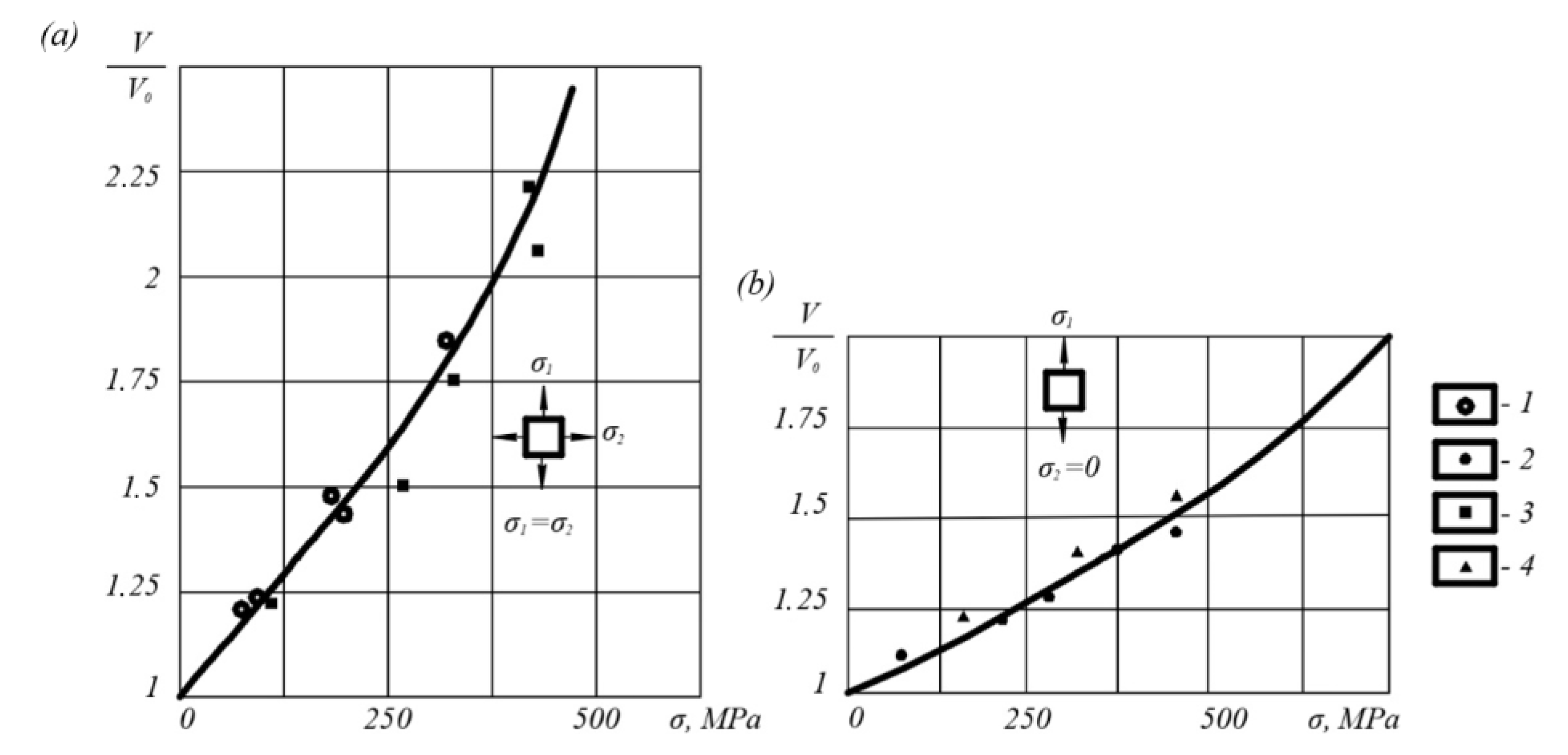
Thus, in a study [15] dependencies were obtained (Figure 2), from which it can be seen that the influence of the level of the stress state on the corrosion rate is manifested for a wide range of steels under different loading methods. The dependence of relative corrosion rate νσ/ν0 on stress intensity σi in the test specimen is close to the form
v σ v 0 = 1 + k σ σ i ,
where νσ and ν0 are corrosion rates in the presence and absence of mechanical stress, mm/year; kσ is the mechanochemical stress coefficient that depends on the type of loading, for example, as can be concluded from the curves (Figure 2): 0.0025 MPa−1 for biaxial bending and 0.0011 MPa−1 for uniaxial bending.
According to [11], the kσ value for steel pipelines can be determined using Formula (2):
k σ = V 1 + σ l o n σ h 3 R T 1 σ l o n σ h + σ l o n σ h 2 ,
where V = M/ρ—molar volume of steel (for carbon steel 7.22·10−6 m3); R—universal gas constant (8.314 J/(K·mol); T—standard temperature (293 K); σh—hoop stresses in the pipeline, MPa; σlon—longitudinal stresses, MPa.
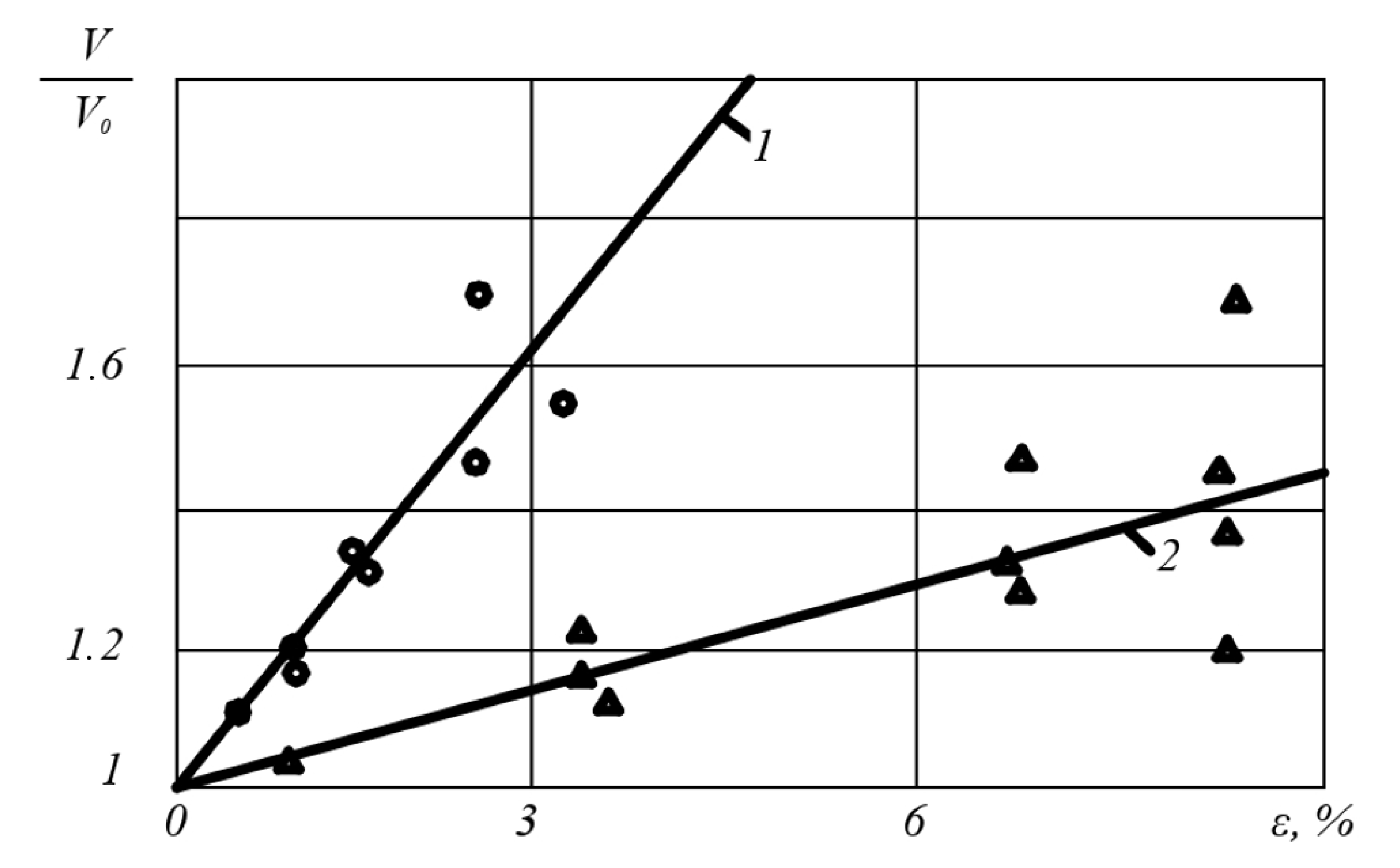
Similarly, the corrosion process is intensified by the preplastic deformation of the metal (Figure 3) [7].
In this case, the dependence of the relative corrosion rate νε/ν0 on the relative strain ε, which the metal of the specimen received in the process of preplastic deformation, is close to the form (3):
ν ε ν 0 = 1 + k ε ε ,
where Vε and V0 are corrosion rates of the specimen with plastically deformed and undeformed metal, mm/year; kε is a coefficient that depends on the steel grade and the type of heat treatment, for example, as can be concluded from the type of curves in Figure 2: ~0.2 for steel 16 GS after hardening and high tempering and ~0.06 for the same steel after complete annealing with air cooling. (In accordance with [15], the kε values for pipeline steels are in the range of 5–24.)
For welded straight-seam pipes formed by bending a sheet billet around a cylindrical mandrel, the degree of achieved relative strain ε can be estimated by the well-known formula:
ε = δ d + δ ,
where δ is the pipe thickness, mm; d is the diameter of the mandrel (inner diameter of the tube), mm.
Authors [7,11] proposed to represent the total effect of the mechanochemical effect in the following form:
ν ν 0 = K m h Σ = K m h σ K m h ε = 1 + k σ i 1 + k ε ε i ,
where ν is the corrosion rate of a steel structure made of plastic -deformed metal under the action of mechanical stresses, mm/year; ν0 is the corrosion rate of an unstressed structure with metal not subject to plastic deformation, mm/year; Kmh(∑) is the coefficient of mechanochemical damageability; Kmh(σ) = (1 + kσ∙σi) is the index of influence of the stress state of the structure; σi is the stress intensity, MPa; Kmh(ε) = (1 + kε∙εi) is the index of influence of metal preliminary plastic deformation; εi is strain intensity.
In the corrosion models presented in Table 1, it is assumed that the stress–strain state of the corroded pipeline wall remains constant over time. At the same time, as shown in the works of P.V. Burkov [9], D.V. Popodko [13], M.R. Shaimukhometov [33], and W. Wang [34], in the presence of a longitudinal notch of a shape close to the groove corrosion trace, the stresses arising in the metal around the notch significantly exceed those occurring in the pipe body. Moreover, as the depth of the notch increases, the stresses arising around it increases. This last circumstance, in our opinion, is the reason for such an intensive deepening of the groove observed on the lower forming line of the oil pipeline during the course of groove corrosion. Below, a kinetic equation is offered on the basis of known dependencies (1)—(5), as well as the results of own computer modeling of the pipeline stress–strain state with a longitudinal notch. It shows a dependence of the groove corrosion rate on the equivalent stresses σ0 in the pipeline during operation and plastic deformation ε, which the pipe material received during its manufacture, allowing calculating the groove depth at every moment of pipeline operation.
Mild steel (~0.2% C, σt = 280 MPa, without special heat treatment) was chosen as the pipe material, with a corrosion rate (v0 = 0.9 mm/year) in formation water with abrasive particles, as was established in [7].

3. Results and Discussion

In the process of computer modeling, first of all, it seemed necessary to analyze the allocation of equivalent stresses arising in the pipe wall metal around the groove and their change as it deepens.
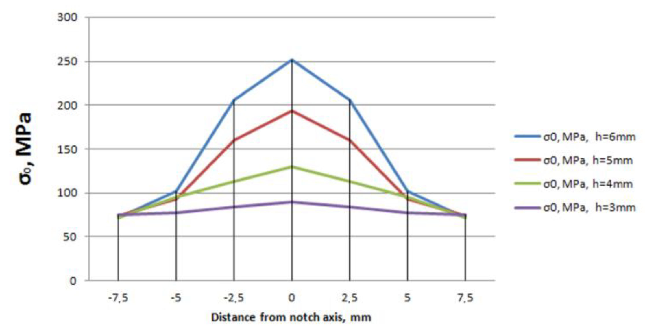
The subjects of the computational analysis were a 10 m long pipeline with segments of four standard sizes (114 × 4, 219 × 6, 325 × 9 and 426 × 10 mm), being the most commonly used as oil-field pipelines. Pipelines were under maximum working pressure PW = 2.0; 2.5; 3.0; and 4.0 MPa for each size. The pipe material was steel typically used for these pipelines with yield point σy = 272 MPa. A longitudinal notch, simulating the most typical groove corrosion trace, was modeled on the inside pipe section along its entire length. This notch had a hemispherical shape with a width of up to 15 mm and a variable depth of 1−6 mm. Longitudinal σlon, hoop σh, and equivalent stresses σ0 were evaluated with different depths of corrosion damage. The calculation was performed via the finite element method based on the model built in the software product ANSYS 2019 R1 with a linear element size of 0.005 m, which provided sufficient accuracy for the calculations (±1 MPa).
The calculated analysis showed that the presence of an elongated defect of certain geometric parameters leads to the indentation of the lower forming section of the pipe into the inner cavity, due to which additional tensile stresses arise in the metal surrounding the notch, the values of which depend on the depth of the groove. A similar effect has been described by a number of authors [13,25,33]. Thus, we can conclude [35] that the maximum values of equivalent stresses σmax are observed at the bottom of the notch (Figure 4).
As the processing of the obtained calculated data showed, the dependence of the stress value in the notch bottom metal σmax on its depth h for all the analyzed pipeline sizes (Figure 5) can be satisfactorily approximated by an exponential function of the form (6):
σ max = σ 0 exp b h ,
where σ0 is the equivalent stress in the pipe walls in the absence of the notch, MPa; b is the dimensional coefficient, which depends on the pipeline parameters and is equal for the analyzed standard sizes to 0.60; 0.49; 0.39; 0.32 mm−1.
By substituting the parameter “stress intensity” σi in Formula (5) for the maximum stress σmax, expressed according to (6) through the equivalent stress in the pipe body σ0, pipe parameter b, and notch depth h, as well as the parameter “strain intensity” εi for the degree of plastic deformation ε of the metal achieved during pipe manufacturing, we obtain the following expression:
ν = ν 0 1 + k σ 0 exp b h 1 + k ε ε i .
After representation of the groove corrosion rate v in the form of the derivative dh/dt and taking the deformation component Kmh(ε) = (1 + kεε) as constant, expression (7) can be represented in the form of the differential Equation (8), integration of which over time from 0 to t allowed us to obtain the dependence of the “groove “ depth on operating time t (9):
d h d t = ν 0 K m h ε 1 + k σ 0 exp b h .
h Σ = h ε + h σ = ν 0 K m h ε t i + k σ 0 b exp b ν 0 K m h ε t i 1 .
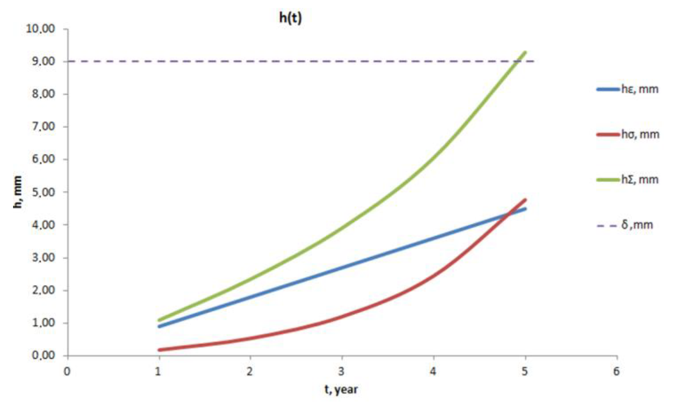
In the derived expression (9), hΣ is the depth of the defect in a pipe made of plastic-deformed material and under the impact of mechanical stresses. In this case, hε is the contribution of the metal-plastic deformation to the value of hΣ, and hσ is the contribution of the pipe stress state to the defect, which changes during operation.
The evaluation of the applicability of Equation (9) for actual oil-field pipelines was carried out using a computational method with the following comparison of defect depths, obtained using in-line diagnostics. The ascending section of 325 × 9 mm oil pipeline (P W = 3 MPa) was chosen as a calculation object, as the section with the highest values of the equivalent stresses [36,37] and the most probable place of groove corrosion. Pipeline carbon steel 20 was selected as the pipe material, with a corrosion rate (ν0 = 0.9 mm/year) in formation water with abrasive particles, as was established in a prior work [7].
As the calculation results showed, under the given operating conditions, equivalent stresses up to 150 MPa arise in the oil pipeline wall. The other values for the proposed kinetic Equation (9) were b = 0.39 m−1, Kmh(ε) = 1.15, and k = 0.0021 MPa−1. The calculated deepening of the corrosion groove hΣ with the mechanochemical components hε and hσ for the operation time is presented in Figure 6.
As it can be seen from Figure 6, the rate of groove deepening v increases with the increase in the pipeline operation time: if during the first year its value is ~1 mm/year (hΣ ~1 mm), then, during five years, its average value is ~2 mm/year (hΣ ~ 10 mm), which, for the given pipe wall thickness (9 mm), corresponds to its through corrosion. This is preceded by the mechanical destruction of the pipe after 4 years of operation due to the metal reaching the bottom of the groove and the yield strength of the material. It is worth noting that the contribution of deformation (hε) and stress (hσ) components to the total damage depth hΣ is approximately equal.
The damage depths (1–10 mm) obtained as a result of the calculation were of the same order as those detected during the inspection of actual pipelines affected by groove corrosion.

4. Conclusions

It was shown that the observed discrepancy in a number of cases in the remaining operating life of the pipelines affected by groove corrosion can be explained by the existing acceleration of the corrosion process rate with a deepening of the groove due to the increasing level of mechanical stresses in the metal surrounding the groove. Mechanical stresses intensify the corrosion process due to the mechanochemical effect. With the use of the literature data and the dependence of the stress in the groove bottom metal on its depth, a kinetic equation was designed. It shows the dependence of the groove corrosion rate on the equivalent stresses in the pipeline during operation and the plastic deformation that the pipe material received during its manufacturing. It allows us to estimate the depth of the groove at every moment of the pipeline’s operation and the residual life of the pipe.

Author Contributions

Conceptualization, G.P.; methodology, G.P. and V.B.; software, G.P. and V.Z.; validation, V.B.; formal analysis, G.P., I.Z. and V.Z.; investigation, G.P.; resources, G.P. and V.B.; data curation, I.Z.; writing—original draft preparation, G.P.; writing—review and editing, V.B., G.P., I.Z. and V.Z.; visualization, G.P.; supervision, V.B.; project administration, V.B. All authors have read and agreed to the published version of the manuscript.

Funding

This research received no external funding.

Data Availability Statement

The data presented in this study are available on request from the corresponding author. The data are not publicly available due to copyright reasons.

Conflicts of Interest

The authors declare no conflict of interest.

References

  1. Goldobina, L.A.; Orlov, P.S. Analysis of the Corrosion Destruction Causes in Underground Pipelines and New Solutions for Increasing Corrosion steel’s Resistance. J. Min. Inst. 2016, 219, 459. [Google Scholar] [CrossRef]
  2. Lyubchik, A.N.; Krapivskii, E.I.; Bolshunova, O.M. Prediction of the technical status of pipeline based on analysis. J. Min. Inst. 2011, 192, 153–156, (In Russian, Abstract in English). [Google Scholar]
  3. Sultanbekov, R.R.; Nazarova, M.N. The influence of total sediment of petroleum products on the corrosiveness of the metal of the tanks during storage. In Proceedings of the E3S Web Conference—I International Conference «Corrosion in the Oil and Gas Industry», Saint Petersburg, Russia, 22–24 May 2019; E3S Web of Conferences: Les Ulis, France, 2019; Volume 121, p. 01015. [Google Scholar] [CrossRef]
  4. Shammazov, I.; Dzhemilev, E.; Sidorkin, D. Improving the Method of Replacing the Defective Sections of Main Oil and Gas Pipelines Using Laser Scanning Data. Appl. Sci. 2023, 13, 48. [Google Scholar] [CrossRef]
  5. Bolobov, V.I.; Latipov, I.U.; Zhukov, V.S.; Popov, G.G. Using the Magnetic Anisotropy Method to Determine Hydrogenated Sections of a Steel Pipeline. Energies 2023, 16, 5585. [Google Scholar] [CrossRef]
  6. Vinogradov, S.N.; Volchihin, V.I.; SHirina, E.V.; Meshcheryakov, A.S. Issledovanie korrozionnoj stojkosti konstrukcionnyh stalej v plastovoj vode [Investigation of corrosion resistance of structural steels in reservoir water]. Izv. Vyss. Uchebnyh Zaved. [News High. Educ. Inst.] 2008, 4, 139–144. (In Russian) [Google Scholar]
  7. Medvedev, A.P. Kompleksnaya Sistema Obespecheniya Bezopasnosti Promyslovyh Truboprovodov Zapadnoj Sibiri [An Integrated Safety System for West Siberian Field Pipelines]. Ph.D. Thesis, Institute of Problems of Transport of Energy Resources of the Republic of Bashkortostan, Ufa, Russia, 2004; p. 44. (In Russian). [Google Scholar]
  8. Medvedev, A.P.; Markin, A.N. Ob usilennoj korrozii truboprovodov sistem sbora nefti NGDU «Belozerneft’» [About increased corrosion of pipelines of oil collection systems NGDU «Belozerneft»]. Neft. Hozyajstvo [Oil Gas Ind.] 1995, 11, 23–24. (In Russian) [Google Scholar]
  9. Burkov, P.V.; Burkov, V.P.; Fat’yanov, D.S.; Timofeev, V.Y. Studying the stress-strain state of oilfield pipelines exposed to rill corrosion. Vestn. Kuzbasskogo Gos. Tekhnicheskogo Univ. [Bull. Kuzbass State Tech. Univ.] 2018, 3, 5–12, (In Russian, Abstract in English). [Google Scholar] [CrossRef]
  10. Abdullin, I.G.; Davydov, S.N.; Hudyakov, M.A. The mechanism of groove destruction of the lower forming pipes of oil collectors. Oil Gas Ind. 1984, 3, 51–53. (In Russian) [Google Scholar]
  11. Zajnullin, R.S. Kinetika mekhanohimicheskogo razrusheniya i resurs truboprovodnyh sistem [Kinetics of mechanochemical destruction and resource of pipeline systems]. Probl. Sbora Podgot. Transp. Neft. Nefteprod. [Probl. Collect. Prep. Transp. Oil Pet. Prod.] 2005, 65, 44–63. (In Russian) [Google Scholar]
  12. Klisenko, L.B.; Lapshin, A.P.; Kudrin, D.V. Probable reasons for the formation of ribbed corrosion in oilfield pipelines detected during technical diagnosis. Mod. Sci. Curr. Probl. Solut. 2015, 9, 58–61. (In Russian) [Google Scholar]
  13. Popod’ko, D.V. Ocenka Bezopasnoj Ekspluatacii Obolochek s «Kanavochnym Iznosom» Metodom Konechnyh Elementov [Evaluation of the Safe Operation of Shells with “Groove Wear” by the Finite Element Method]. Ph.D. Thesis, Ufa State Petroleum Technological University (USPTU), Ufa, Russia, 2004; p. 24. (In Russian). [Google Scholar]
  14. Bolobov, V.I.; Popov, G.G. Methodology for testing pipeline steels for resistance to grooving corrosion. J. Min. Inst. 2021, 252, 854–860. [Google Scholar] [CrossRef]
  15. Gutman, E.M.; Zajnullin, R.S.; Zaripov, R.A. Kinetika mekhanohimicheskogo razrusheniya i dolgovechnost’ rastyanutyh konstruktivnyh elementov pri uprugo-plasticheskih deformaciyah [Kinetics of mechanochemical destruction and durability of stretched structural elements under elastic-plastic deformations]. Fiz.-Him. Mekhanika Mater. [Phys.-Chem. Mech. Mater.] 1984, 2, 14–17. (In Russian) [Google Scholar]
  16. Zajnullin, R.S. K metodike korrozionnyh ispytanij metalla pri dvuhosnom napryazhennom sostoyanii [To the method of corrosion testing of metal in a biaxial stress state]. Fiz.-Him. Mekhanika Mater. [Phys.-Chem. Mech. Mater.] 1983, 9, 683–695. (In Russian) [Google Scholar]
  17. Mansour, M.A.; Alfantazi, A.M.; Elboujdaini, M. Sulfide stress cracking resistance of API-X100 high strength low alloy steel. Mater. Des. 2009, 30, 4088–4094. [Google Scholar] [CrossRef]
  18. Dergach, T.O.; Sukhomlin, G.D. Methods for the Improvement of Corrosion Resistance of Low-Alloy Steel Pipes for the Oil-And-Gas Extraction Industry. Mater. Sci. 2021, 56, 684–690. [Google Scholar] [CrossRef]
  19. Sultanbekov, R.; Islamov, S.; Mardashov, D.; Beloglazov, I.; Hemmingsen, T. Research of the Influence of Marine Residual Fuel Composition on Sedimentation Due to Incompatibility. J. Mar. Sci. Eng. 2021, 9, 1067. [Google Scholar] [CrossRef]
  20. Askari, M.A.; Aliofkhazraei, M.; Afroukhteh, S. Comprehensive review on internal corrosion and cracking of oil and gas pipelines. J. Nat. Gas Sci. Eng. 2019, 71, 102971. [Google Scholar] [CrossRef]
  21. Hasan, F.; Iqbal, J.; Ahmed, F. Stress corrosion failure of high-pressure gas pipeline. Eng. Fail. Anal. 2007, 14, 801–809. [Google Scholar] [CrossRef]
  22. Saleem, B.; Ahmed, F.; Rafiq, M.A.; Ajmal, M.; Ali, L. Stress corrosion failure of an X52 grade gas pipeline. Eng. Fail. Anal. 2014, 46, 157–165. [Google Scholar] [CrossRef]
  23. Abaev, Z.K.; Galachieva, S.V. Mathematical model elaboration in terms of baking time influence on the resistance to stress corrosion cracking under tension. In Proceedings of the International Conference on Industrial Engineering, Applications and Manufacturing (ICIEAM), Chelyabinsk, Russia, 19–20 May 2016; IEEE: Manhattan, NY, USA, 2016; Volume 2, pp. 1–4. [Google Scholar] [CrossRef]
  24. Darowicki, K.; Orlikowski, J.; Arutunow, A. Dynamic electrochemical impedance spectroscopy measurements of passive layer cracking under static tensile stresses. Solid State Electrochem. 2004, 8, 352–359. [Google Scholar] [CrossRef]
  25. Griggs, J.; Gamboa, E.; Lavigne, O. A review of modelling high pH stress corrosion cracking of high-pressure gas pipelines. Mater. Corros. 2015, 67, 251–263. [Google Scholar] [CrossRef]
  26. Kundyanova, U.P. Modelirovanie ruchejkovoj korrozii polosti truboprovoda [Modeling of rivulet corrosion of the pipeline cavity]. In Sovremennye Tekhnika i Tekhnologii: Sbornik Trudov XX Mezhdunarodnoj Nauchno-Prakticheskoj Konferencii Studentov, Aspirantov i Molodyh Uchenyh [Modern Equipment and Technologies: Proceedings of the XX International Scientific and Practical Conference of Students, Postgraduates and Young Scientists], Tomsk, Russia, 14–18 April 2014; The National Research Tomsk Polytechnic University: Tomsk, Russia, 2014; Volume 2, pp. 49–50. (In Russian) [Google Scholar]
  27. Kolikov, A.P.; Leletko, A.S.; Matveev, D.B.; Kulyutin, S.A.; Kadil’nikov, S.V. Investigation of residual stresses in welded pipes. Izv. Ferr. Metall. 2014, 57, 48–53, (In Russian, Abstract in English). [Google Scholar] [CrossRef]
  28. Shinkin, V.N. Residual stresses during expansion of a steel pipe. Molod. Uchenyi [Young Sci.] 2015, 20, 88–93. (In Russian) [Google Scholar]
  29. Shchipachev, A.M.; Gorbachev, S.V. Influence of post-welding processing on continuous corrosion rate and microstructure of welded joints of steel 20 and 30KHGSA. J. Min. Inst. 2018, 231, 307–311. [Google Scholar] [CrossRef]
  30. Ren, R.K.; Zhang, S.; Pang, X.L.; Gao, K.W. A novel observation of the interaction between the macroelastic stress and electrochemical corrosion of low carbon steel in 3.5 wt.% NaCl solution. Electrochim. Acta 2012, 85, 283–294. [Google Scholar] [CrossRef]
  31. Wang, X.; Tang, X.; Wang, L.; Wang, C.; Zhou, W. Synergistic effect of stray current and stress on corrosion of API X65 steel. J. Nat. Gas Sci. Eng. 2014, 21, 474–480. [Google Scholar] [CrossRef]
  32. Ovchinnikov, I.G.; Ovchinnikov, I.I.; Bashirzade, S.R. Prognozirovanie povedeniya truboprovodnyh konstrukcij v slozhnyh gruntovo-geologicheskih usloviyah. CHast’ 1. Obobshchennaya model’ deformirovaniya truboprovoda [Predicting the behavior of pipeline structures in difficult ground-geological conditions. Part 1. Generalized model of pipeline deformation]. Naukoved. [Sci. Stud.] 2016, 8, 99. (In Russian) [Google Scholar]
  33. Shaymuhametov, M.R. Tensions in the Area of Groove Destruction of Pipelines. Oil Gas Bus. 2009, 2, 115–120, (In Russian, Abstract in English). [Google Scholar]
  34. Chen, Z.F.; Wang, W.; Yang, H.; Yan, S.T.; Jin, Z.J. On the effect of long corrosion defect and axial tension on the burst pressure of subsea pipelines. Appl. Ocean Res. 2021, 111, 102637. [Google Scholar] [CrossRef]
  35. Zlotin, V.A.; Popov, G.G.; Bolobov, V.I. Raschyotnyj analiz raspredeleniya napryazhenij v stenke truboprovoda pri nalichii na eyo poverhnosti nadreza razlichnoj glubiny [Computational analysis of the stress distribution in the pipeline wall in the presence of an incision of various depths on its surface]. In Sovremennye Obrazovatel’nye Tekhnologii v Podgotovke Specialistov Dlya Mine-Ral’no-Syr’evogo Kompleksa [Modern Educational Technologies in the Training of Specialists for the Mineral Resource Complex], Saint-Petersburg, Russia, 5–6 March 2020; Saint Petersburg Mining University: Saint-Petersburg, Russia, 2020; pp. 1324–1329. (In Russian) [Google Scholar]
  36. Firstov, A.A.; Kapachinskih, Z.Y.; Seredenok, V.A. Obosnovanie vozmozhnosti ocenki urovnya izgibnyh napryazhenij v stenkah trub magistral’nyh gazonefteprovodov opredeleniem ego prostranstvennogo polozheniya s poverhnosti grunta [Substantiation of the possibility of assessing the level of bending stresses in the walls of pipes of main gas and oil pipelines by determining its spatial position from the ground surface]. Nauka Tekhnika Gazov. Promyshlennosti [Sci. Technol. Gas Ind.] 2020, 2, 89–98. (In Russian) [Google Scholar]
  37. Aginey, R.V.; Firstov, A.A.; Kapachinskikh, Z.Y. To the question of determining bending stress of a buried pipeline from the ground surface. In Proceedings of the International Conference on Innovations, Physical Studies and Digitalization in Mining Engineering (IPDME 2020), Saint-Petersburg, Russia, 23–24 April 2020; IOP: Bristol, UK, 2020; Volume 1753, p. 012068. [Google Scholar] [CrossRef]
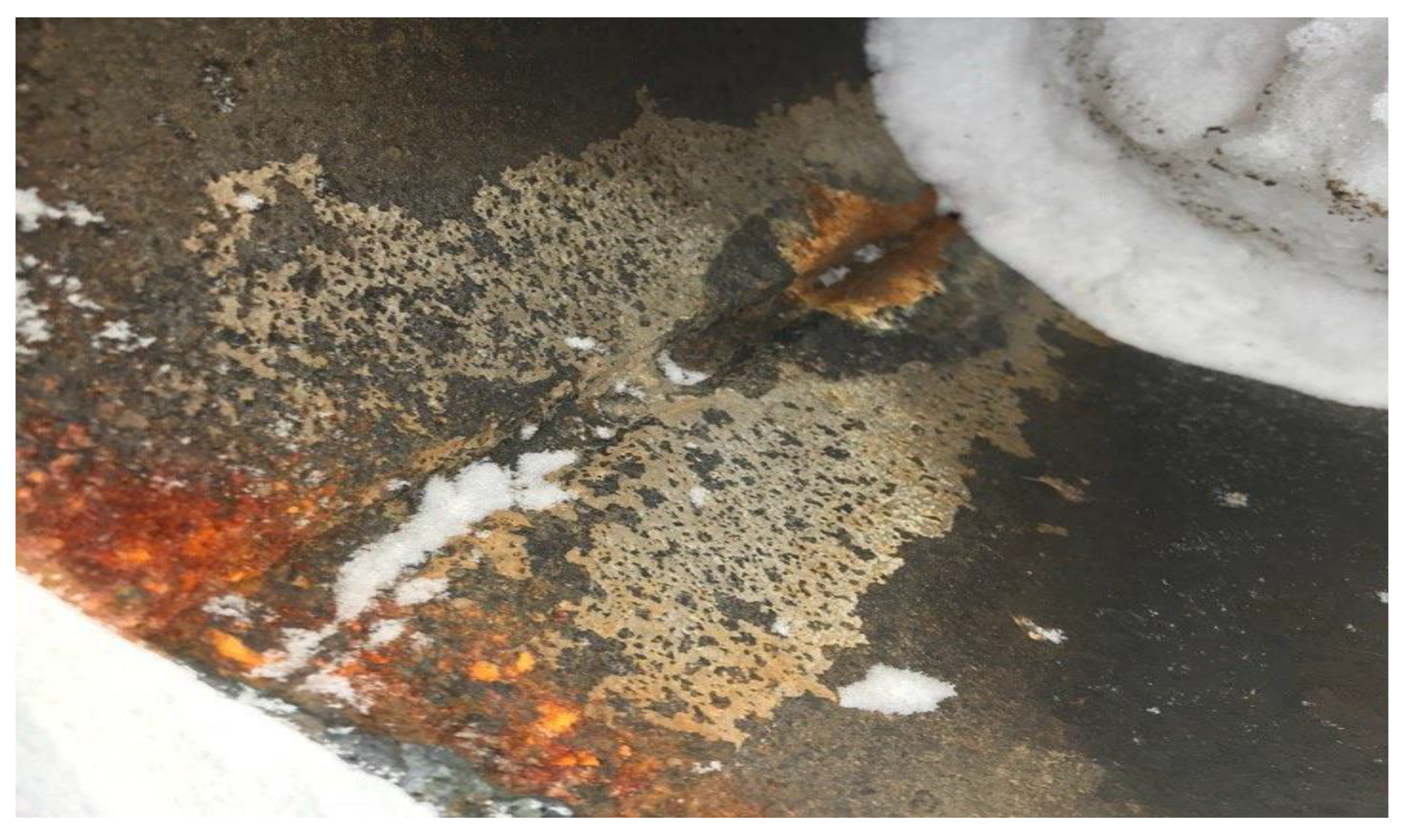
Figure 1. Oil pipeline section with groove corrosion damage.
Energies 16 07067 g001
Figure 2. Dependence of relative corrosion rate of steels St3 (~0.3% C) (1), 20 (~0.2% C) (2), 45 (~0.37−0.45% C) (3), and U8 (~0.75−0.84% C) (4) on stress value in the test specimen at its biaxial (a) and uniaxial (b) bending (medium—water solution of HCl) [15].
Energies 16 07067 g002
Figure 3. Relative corrosion rate of 16GS (~0.12–0.18% C; 0.40–0.70% Si; 0.90–1.20% Mn) steel after quenching with tempering (1) and normalization (2) depending on the degree of plastic deformation of the test sample (medium—aqueous solution of HCl) [7].
Energies 16 07067 g003
Figure 4. Allocation of equivalent stresses at the pipe section 325 × 9 mm at different notch depths h.
Energies 16 07067 g004
Figure 5. Dependence of maximum equivalent stresses σmax in the metal surrounding the bottom of the groove, depending on the depth h for different pipe sizes.
Energies 16 07067 g005
Figure 6. Dependence of groove depth on operating time for a pipeline of 325 × 9 mm size with internal pressure of 3 MPa (dashed line—original pipe wall thickness; tp—time to reach through wall damage).
Energies 16 07067 g006
Table 1. Different models of corrosion damage [32].
Deterministic (Phenomenological)Stochastic (Probabilistic)Unclear (Linguistic)
d δ d t = ν 0 + k σ δ ˜ t = k ˜ t k t ˜ i n c n ν 0 = i 2 N α 1 μ ν 0 i ν 0 i , ν 0 i ν 0 ; ν 0 + , μ ν 0 i = 0 , ν 0 i ν 0 ; ν 0 + cos π ν c p ν 0 i ν 0 + ν 0 , ν 0 i ν 0 ; ν 0 + .
d δ d t = ν 0 1 + k Э
d δ d t = ν 0 ψ t 1 + k σ
d δ d t = ν 0 exp V σ R T
In this table δ—depth of corrosion damage, mm; t—reaction time, s; σ—mechanical stress, MPa; T—temperature, K; Э—specific energy, J; v0—corrosion rate of unstressed metal, mm/year; k—the coefficient that takes into account the influence of the stress state on the corrosion rate, μ—identity function, ∑ is a discrete fuzzy set, and the remaining values are defined by the experimental data coefficients or functions.
Disclaimer/Publisher’s Note: The statements, opinions and data contained in all publications are solely those of the individual author(s) and contributor(s) and not of MDPI and/or the editor(s). MDPI and/or the editor(s) disclaim responsibility for any injury to people or property resulting from any ideas, methods, instructions or products referred to in the content.