1. Introduction
In recent years, the use of Inductive Power Transfer (IPT) has increased in many applications where cables are not desired or cannot be used, such as medical implants [
1], wireless sensor nodes [
2], smart textile wearable devices [
3], electrical vehicles [
4], and robots [
5]. Typically, IPT systems are based on coupled-mode theory in an oscillating electromagnetic field with a transmitter coil (TX) and a receiver coil (RX), respectively.
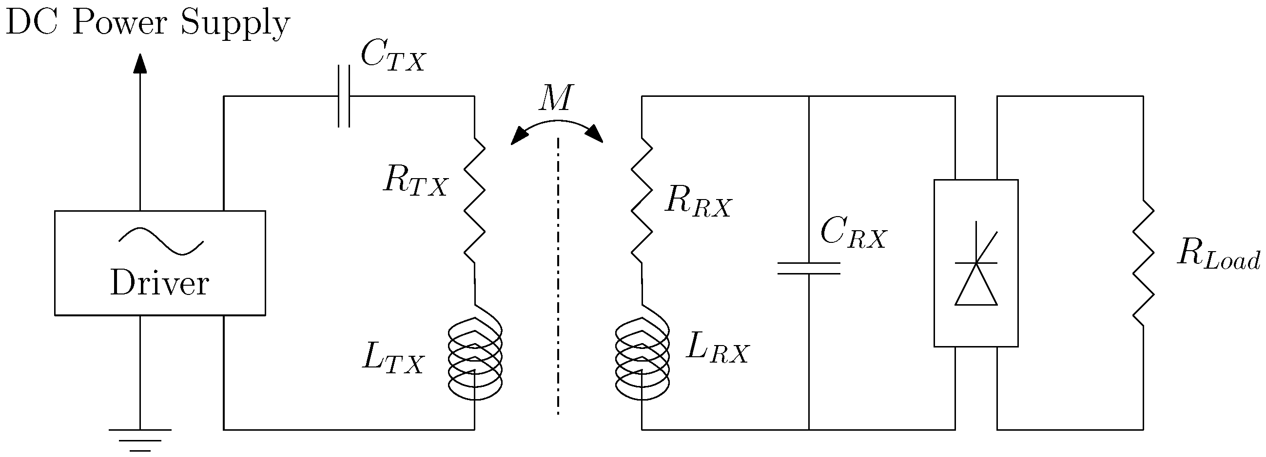
Figure 1 shows the TX and RX coils that are represented by inductors
and
, with their equivalent series resistances represented by
and
, respectively [
6]. The resonant capacitor
is connected in series with
, and the resonant capacitor
is connected in parallel with
. Both coils are connected to a compensation capacitor to reach the resonance at the same operating frequency
, where the transmitted power and the system’s efficiency increase. These capacitors can be connected in various arrangements: serial–serial (SS), serial–parallel (SP), parallel–parallel (PP), and parallel–serial (PS). For textile applications, the SP arrangement is the most advantageous since it ensures a higher power transfer efficiency (PTE) compared to other topologies [
7]. The load, represented by the resistance
, is powered by the rectified DC voltage from the receiver circuit. The resistances (
and
) introduced by the coupled coils waste power when the alternating currents pass through the coil, thereby reducing the system’s efficiency. These losses due to the resistances decrease the power transfer efficiency. Consequently, these resistances should be as small as possible.
IPT allows for power transfer between two or more circuits without a physical connection thanks to mutual inductance (
M). The design of an IPT system is based on electronic circuits [
8], the remote control circuits [
9], and the coils’ design [
10]. The coils’ form factor and design parameters can affect the system’s ability to be integrated into various applications, the system’s power transfer efficiency, and the fabrication cost. Consequently, the investigation of the coils’ efficiency is increasingly recommended considering their geometric specifications. Effectively, these geometric parameter values in terms of the number of turns (
n), the trace width (
w), the spacing between wires (
s), and the inner and outer diameters (
,
, respectively) have a strong effect on the coils’ performance. Coils can be fabricated using different materials such as copper [
11], silver [
12], coated yarn [
13], nanocomposites [
14], etc. The materials and fabrication techniques used for the coils in a wireless power transfer system can significantly impact its efficiency. Consider the following crucial elements:
- -
Conductivity: coil materials with high electrical conductivity such as copper or silver can minimize resistive losses and improve system efficiency. Higher conductivity allows a higher current to pass through the coil, resulting in less energy loss as heat.
- -
Resistance: Lower resistance in coil materials minimizes power losses caused by Joule heating. When the resistance of a coil is high, more electrical energy is converted to heat, resulting in lower efficiency. As a result, low-resistance materials such as copper or silver are widely used in high-efficiency systems.
- -
Fabrication process: The fabrication method used to create the coil can have an impact on its efficiency. Precision winding techniques, for example, automated fabrication operations, can improve coil performance and efficiency by decreasing manufacturing mistakes and assuring uniformity. Furthermore, contemporary techniques like laser cutting and additive manufacturing can enhance design flexibility and allow for the production of more efficient coil shapes [
15,
16,
17].
In the literature, various WPT systems have been proposed; however, they still suffer from low power transfer efficiency. Coils designed with 100 % PTE remain a challenge. In the next section, we illustrate some previous work related to this application.
The design of coils with a high PTE and a small coil are conflicting goals. The main objective behind the coils’ optimization is to increase the coil quality factor (
) as much as possible. This specific parameter increases the mutual inductance (M). It has a great impact on the power transfer efficiency. To shed light on the relation between the coil quality factor, power transfer efficiency, and mutual inductance between two coils we can refer to the following equation [
17]:
Here,
and
represent the coil quality factors of the two coils involved, whereas
K denotes the coupling factor that reflects the mutual inductance between the coils. The mutual inductance, represented by the coupling factor (
K), captures the degree of magnetic coupling between two coils. It indicates how strong the magnetic field produced by one coil can induce a voltage in the other coil. This concept is fundamental in wireless power transfer systems, as it determines the efficiency of transferring power from the transmitter coil to the receiver coil. The mutual inductance between two coils is calculated as follows [
18]:
where
M is the mutual inductance between the coils,
is the self-inductance of the first coil,
is the self-inductance of the second coil, and
K is the coupling coefficient between the coils.
To address the problem of the coil’s power losses in the form of heat (high resistivity, in this work), we used the spiral coil shape while calculating its length and resistance. Then, we proposed to approximate the spiral model to a circular model. Later, we compared the two coil length calculation methods with different IPT system properties. The main contribution is related to validating the circular shape approximation in a certain domain of the geometry parameters. This allows the coil designer to choose the appropriate coil parameters to adopt in his application.
The rest of this paper is organized as follows.
Section 2 presents previous research works related to improving WPT efficiency in the RIC WPT system.
Section 3 develops the calculation of the quality factor
of the spiral shape and the approximated circular coil shape.
Section 4 presents a comparison of the two models and a FEM validation using COMSOL software.
Section 5 provides a discussion of the obtained results. Finally, the conclusions are presented in
Section 6.
2. Related Works
In the literature, extensive research has been conducted to investigate various optimization strategies that can successfully increase the power transfer efficiency (PTE) in a WPT system. Several researches have focused on the geometries of the used coils [
19], as well as the materials used [
20], which have a strong impact on the coil’s internal resistance and self-inductance, as we explained in the previous section. The obtained results have shown that spiral coils are the most appropriate for resonant inductive coupling applications [
21]. In terms of materials, silver represents a great choice for constructing coils due to its superior conductivity compared to other materials. It has a very high conductivity, making it an excellent choice for establishing effective electrical conduction in coils [
22]. Furthermore, the technology of the coil fabrication has a higher impact on their performance [
23]. Let us consider the textile coil example. In [
24], the authors presented a comparison of different fabrication techniques for textile applications, such as sewn, embroidered, laser cut, and printed induction coils for wireless power transfer. The results showed that the embroidered technique is the most precise and efficient for textile applications. Each fabrication method may be suitable for a precise WPT application (WPT for medical implants, robots, etc.).
Certainly, the material used and the coil fabrication method are important criteria for reaching a high PTE but it is not enough. Ensuring a high PTE still requires further optimization. Subsequently, various optimization methods have been suggested. These methods are based on the finite element method (FEM) [
25], modification of the coil model (addition of a magnet for shielding) [
26,
27], or coil analytic models [
28,
29]. The investigation of the optimal coil parameters through FEM simulation shows a higher execution time and the requirement for specific modern tools that are not always available. The addition of a magnet for shielding the coil is not suitable for all WPT applications. Let us always take the example of WPT for textile applications: the addition of a magnet for shielding the coil makes the system uncomfortable for users. For this reason, this optimization method is unsuitable for such an application. Optimization through analytical methods is garnering increasing interest, where the main challenge is the coil model that may show a higher deviation compared to reality [
28]. Therefore, FEM validation is highly recommended. The coil resistance depends in particular on the coil length that may be presented in a simplified model (circular shape) or a complex model (spiral shape). The higher precision models are sometimes avoided due to their complexity from the use of assumptions. However, the selection of the proper model and optimization procedure of the system is still challenging for certain applications that require different design constraints (frequency, coil size, etc.).
After conducting extensive research on wireless power transfer systems through a literature review, it was found that there is currently no existing model of a coil that has a PTE of 100%. The authors of [
30] proposed a numerical and analytical analysis of the wireless power transfer (WPT) system using spiral coils. They achieved 75% efficiency. Another research work was carried out by Zuolni Li and his research team [
6] with the aim of increasing the power transfer efficiency using spiral coils. They proposed a WPT system with one transmitter coil and eight receiver coils for textile applications. The system can achieve an efficiency of 25.1%.
While there are many innovative and effective WPT systems, they still suffer from power losses, resulting in a low power transfer efficiency. This indicates that there is still room for further research and development in this field to achieve higher efficiency rates and improve WPT technology.
Park et al. [
31] have realized experiments on printed circular coils to ensure the maximum quality factor validating theoretical results.
The PTE efficiency is very important in WPY systems since it ensures to power efficiently the target load for various applications such as smart wearable devices and biomedical implants. One method used to improve this parameter is coil geometry optimization. As we explained in the introduction, the objective of this work is to propose a simple calculation method to determine the optimal coil parameters that increase the coil quality factor. Consequently, we improve the PTE, as explained in Equation (
1). In the following section, we explain the theoretical framework of the coil models and the optimized expression of the coil quality factor
based on a circular model.
3. Theoretical Framework of the Coil Models
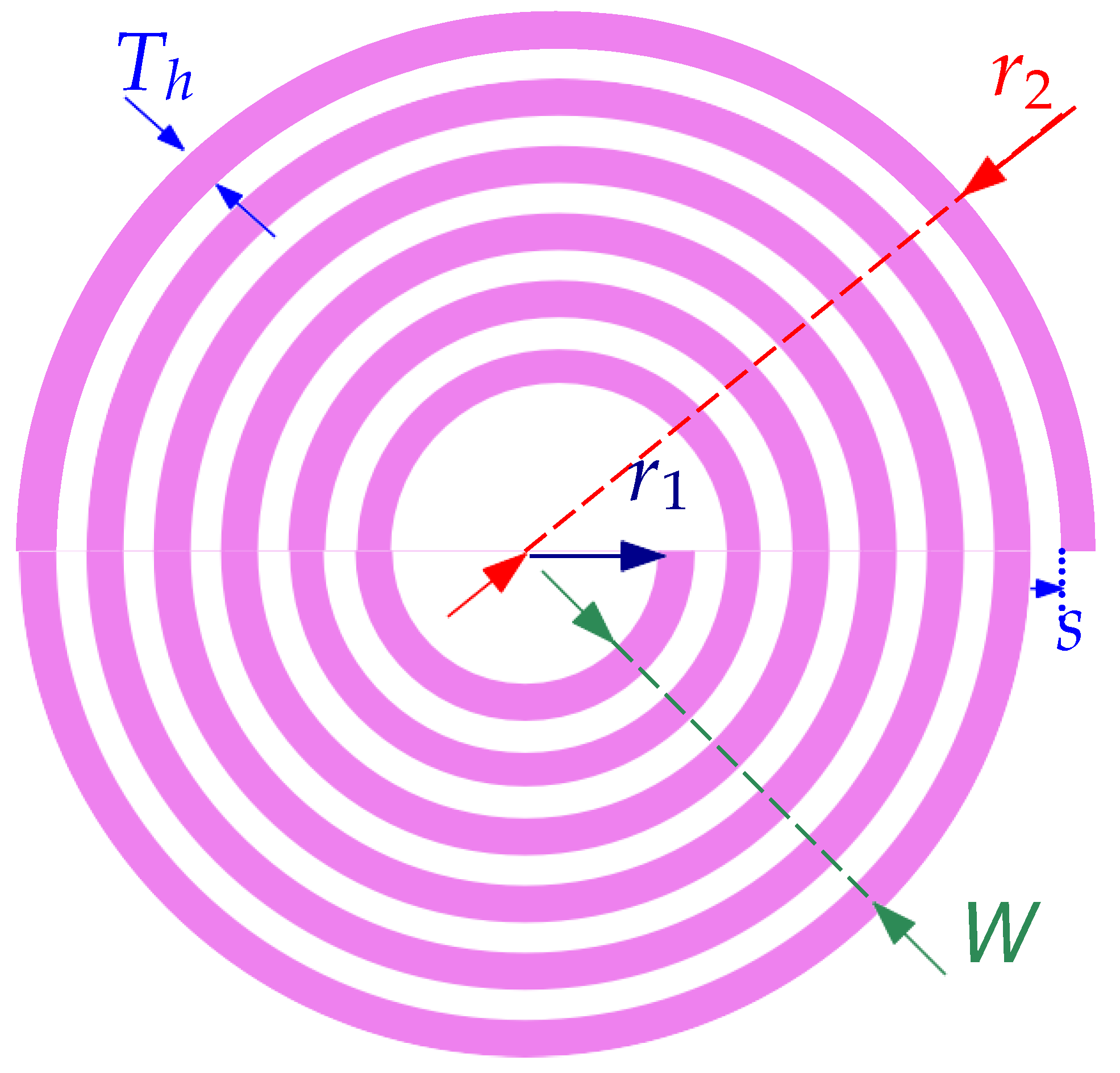
The spiral planar coil illustrated in
Figure 2 presents the geometric specifications that have a strong relationship with the equivalent coil components defined in
Figure 1. These spiral coils are generally characterized by their number of turns (
N), internal radius (
), external radius (
), spacing between coil lines (
s), and coil line width (
W). Additionally, the planar coils present a specific wire width
(its thickness), which is related mainly to the fabrication technology and materials used [
32].
The coil quality factor at the operating frequency
is determined, as shown in Equation (
3), as the ratio between the coil self-inductance
and the coil internal resistance
. The coil self-inductance and internal resistance depend on the coil geometry and materials used.
For a spiral coil shape, the coil self-inductance [
33] is illustrated in Equation (
4). It depends on the average coil diameter (
R), the number of turns (
N), and the coil’s line width (
W), which are expressed in Equations (
5)–(
7), respectively [
33].
with:
The self-inductance of the coil is represented in Equation (
8) by substituting the average coil diameter
R and the coil’s line width
W with their expressions presented in Equations (
5) and (
7), respectively.
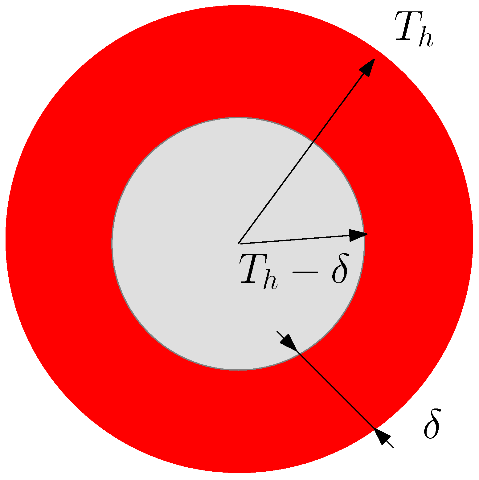
On the other hand, the coil internal resistance
of the planar spiral coil is expressed as shown in Equation (
9), where
is the resistivity of the wire,
is the wire length, and
A is the wire section through which the current flows. In fact, for a high-current AC signal, a skin effect can appear where the current flows in the extremity of the conductor wire, as shown in
Figure 3. In this case, the skin depth (
) is the surface where the current flow is given by Equation (
10), and the wire section within becomes expressed by Equation (
11)
where
H/m is the magnetic permeability,
is the relative permeability of the conductor,
f is the current frequency, and
is the conductor resistivity.
3.1. Modeling of Spiral Coil Length
The spiral coil geometry is defined as a curve that traces the path of a point rotating about a fixed point while continuously increasing its distance from that point. The difference between circular and spiral coils lies in their lengths. A spiral coil is longer in comparison to its diameter, and the distance between its two loops is greater. On the other hand, a circular coil has a larger diameter, and the distance between its two loops is shorter relative to its diameter. The exact length of a spiral coil is defined by its spiral shape. We consider a point
P belonging to the coil’s axis. The coordinates of
P can be expressed as follows:
where
The variation of the position of the point
P with respect to
can be represented by the speed vector:
The total length
of the coil can be expressed as:
with
.
3.2. Modeling of Circular Coil
In the case where the coil spacing (
s) and the wire width (
) are too small compared to the coil radius (
), the coil shape can be approximated by circular turns. In this condition, the one-turn coil length is expressed as
. Then, the expression of the coil length becomes:
In the approximation of the coil to
N circular turns, the radius and length of these turns are
for
, and
and
are the radius and length of a turn
. Thus, the expression of the coil length
becomes
3.3. Quality Factor Optimization Based on Circular Coil
The investigation of the quality factor for the spiral and circular coil shapes can be expressed in different forms according to the coil length. In fact, the spiral coil length expressed previously in Equation (
16), shows a complicated formula that needs to be implemented. However, for the circular coil shape, a reformulation of the quality factor model can be easily expressed as:
To maximize the value of the quality factor according to the coil radius, the derivative of
with respect to
is expressed as:
Then, the maximum of
requires the following condition:
This equation presents two solutions, as presented in Equations (
23) and (
24). The first solution, given in Equation (
23), delivers a condition of the inner radius
, which is about 4 times higher than the outer coil radius
. This solution is not possible due to the fact that the inner radius must be smaller than the outer radius. The second solution, shown in Equation (
24), represents the optimal solution.
4. Comparison between Spiral and Circular Coil Models
The described models for the coil length and internal resistance were investigated for an IPT for wearable applications through the development of the model in MATLAB, as well as an FEM simulation based on COMSOL 5.3a software.
The proposed system is intended to work within Qi standards based on the commercial transmitter side with a frequency of 100 kHz and a commercial transmitter coil. For that, a design of the receiver coil with a higher quality factor is recommended. The design coil parameter constraints of the proposed coil are given in
Table 1.
4.1. Investigation of the Coil Length and Quality Factor of Circular and Spiral Coils
To define the optimal spacing (
s) value that provides the highest coil quality factor in this case,
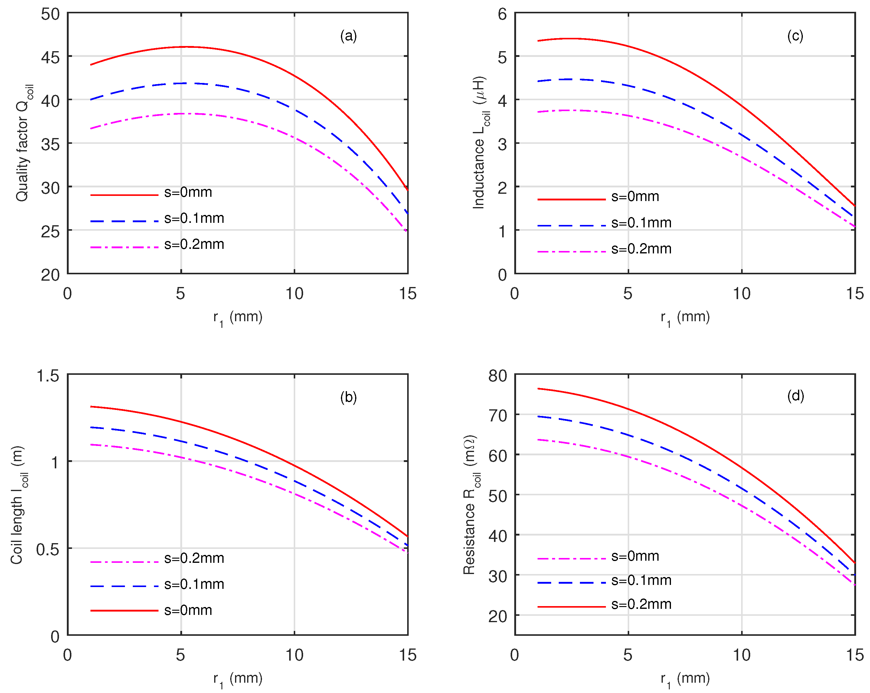
Figure 4 presents the evolution of the coil quality factor
in terms of the internal radius
for different values of
s (
mm) and for the wire width
1 mm. According to this figure, the highest coil quality factor (
) corresponds to the lowest spacing (
) and an internal radius of
mm. However, the case where
mm cannot be applied during the fabrication process; therefore,
mm can be defined as the optimal spacing between wires.
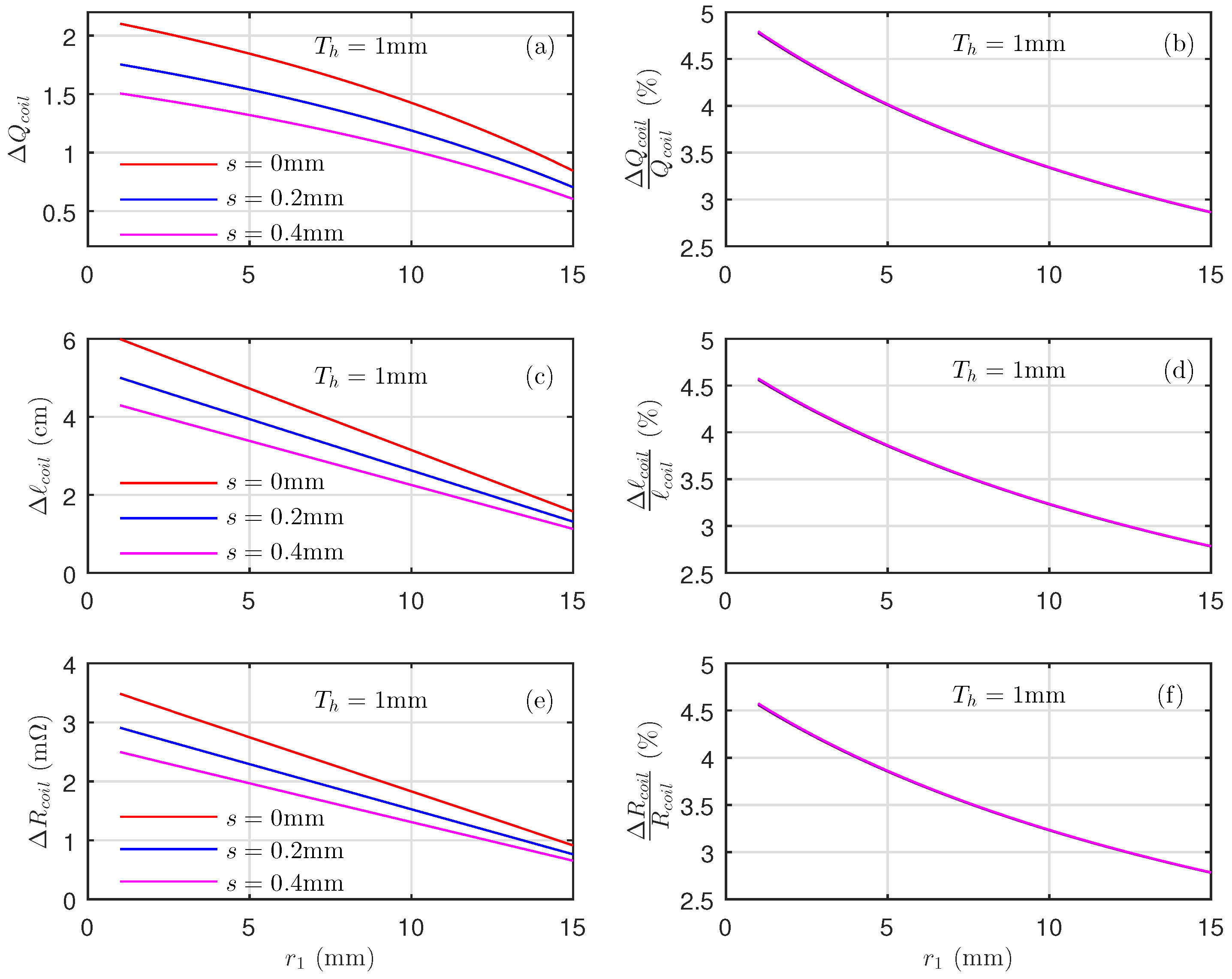
Figure 5 presents the absolute values of the deviations between the spiral shape and the circular shape during the computation of (a) the coil quality factor deviation
, (c) the coil length deviation
, and (e) the coil resistance deviation
in terms of spacing (
mm) between the coil lines for the internal radius
mm and wire width
1mm. This figure also presents the evolution of (b) the quality factor relative deviation
, (d) the wire length relative deviation
, and (f) the evolution of its resistance relative deviation
with respect to the internal radius
, spacing
mm, and wire width
mm.
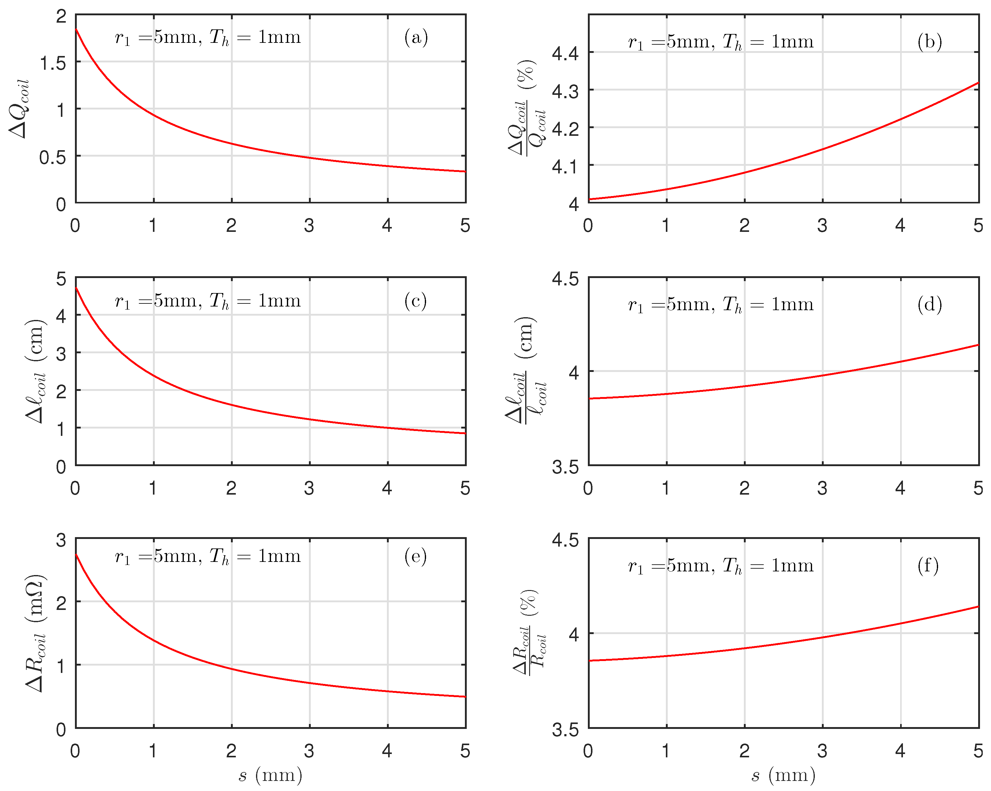
Figure 6 presents the deviation between the spiral shape and the circular shape during the computation of (a) the coil quality factor deviation
, (c) the coil length
, (e) and the coil resistance
in terms of the spacing (
mm) between the coil lines for the internal radius
mm and wire width
mm. This figure also presents the evolution of (b) the quality factor relative deviation
, (d) the evolution of its wire length relative deviations
, and (f) and its resistance relative deviation
.
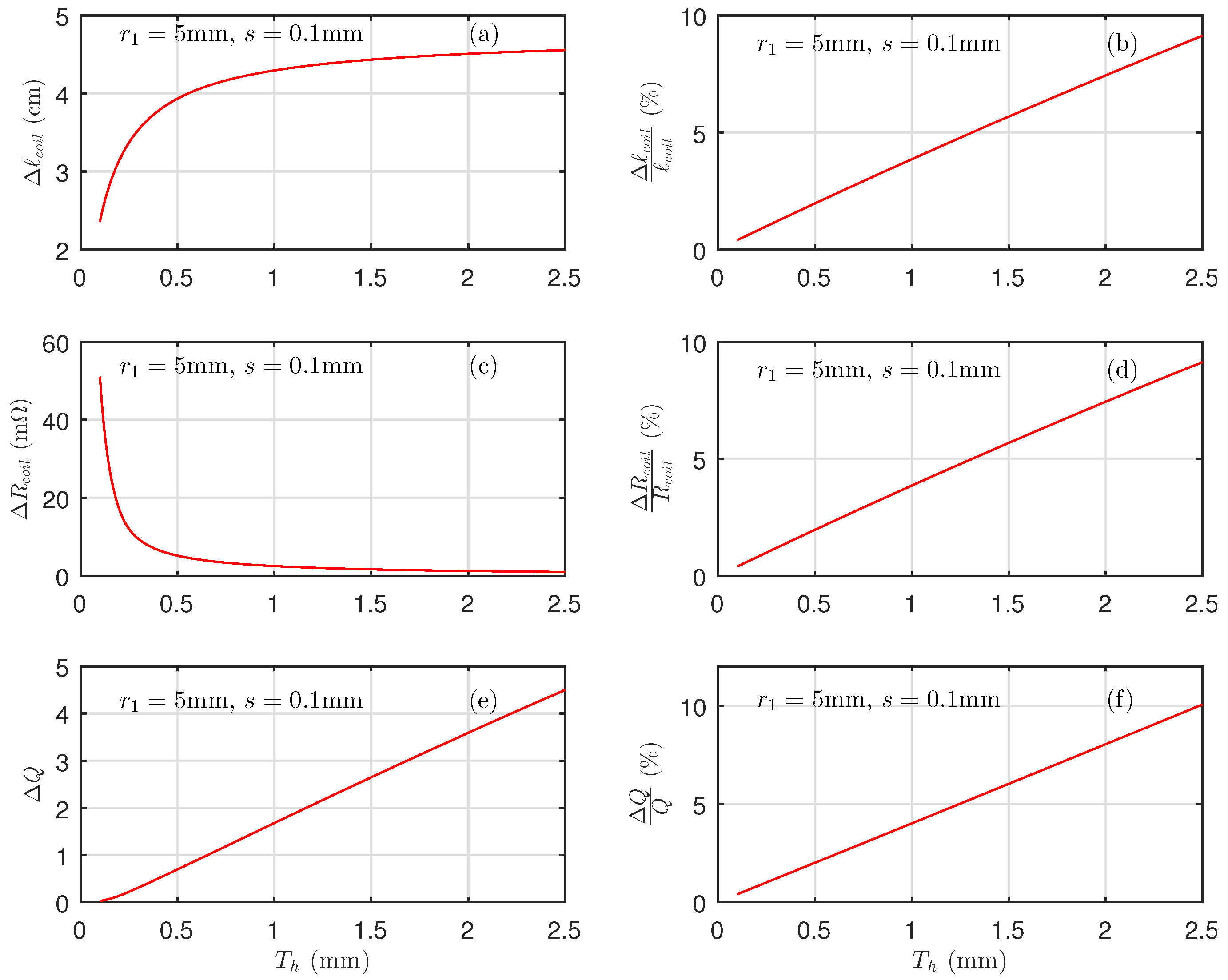
Figure 7 presents the deviation between the spiral shape and the circular shape during the computation of (a) the coil quality factor absolute deviation
, (c) the coil length absolute deviation
, and (f) the coil resistance absolute deviation in terms of the spacing
mm between the coil lines for the internal radius
mm and wire width
mm. This figure also presents the evolution of (b) the quality factor relative deviation
, (d) the evolution of its wire length relative deviation
, and (f) its resistance relative deviation
.
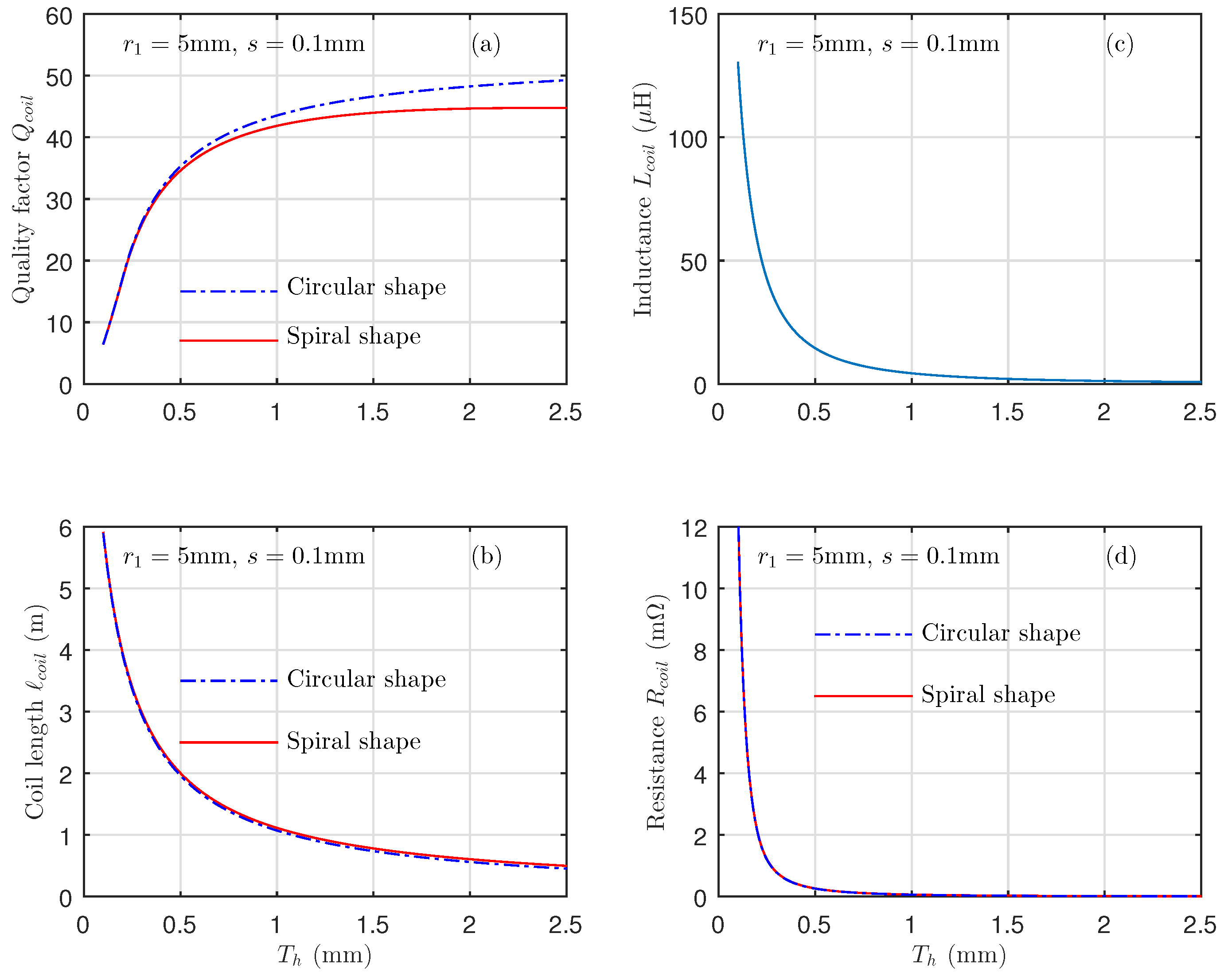
Figure 8 presents the evolution of the coil quality factor
, its wire length (
), the coil inductance (
), and the coil internal radius (
) with the wire width
mm for the internal radius
mm and spacing
mm. These results are for the exact model (spiral shape) and the approximated model (circular shape) using the same coil design constraints. The results show that the approximation is valid for
mm.
Table 2 presents the quality factor’s absolute and relative deviation values
and
, its resistance absolute and relative deviation values
and
, and its wire length absolute and relative deviation values
and
for the internal radius
mm, spacing
mm, and wire width
mm. The absolute deviations of
,
, and
are 1.68, 4.3 cm, and 2.5 m
, respectively.
The relative deviations defined by , , and are around 4%.
These results show that the approximation of the circular windings instead of the spiral shape yields adequate results. This is why we can adopt the approximation of circular winding in the computation of the wire length.
4.2. Simulation Validation Using COMSOL Software
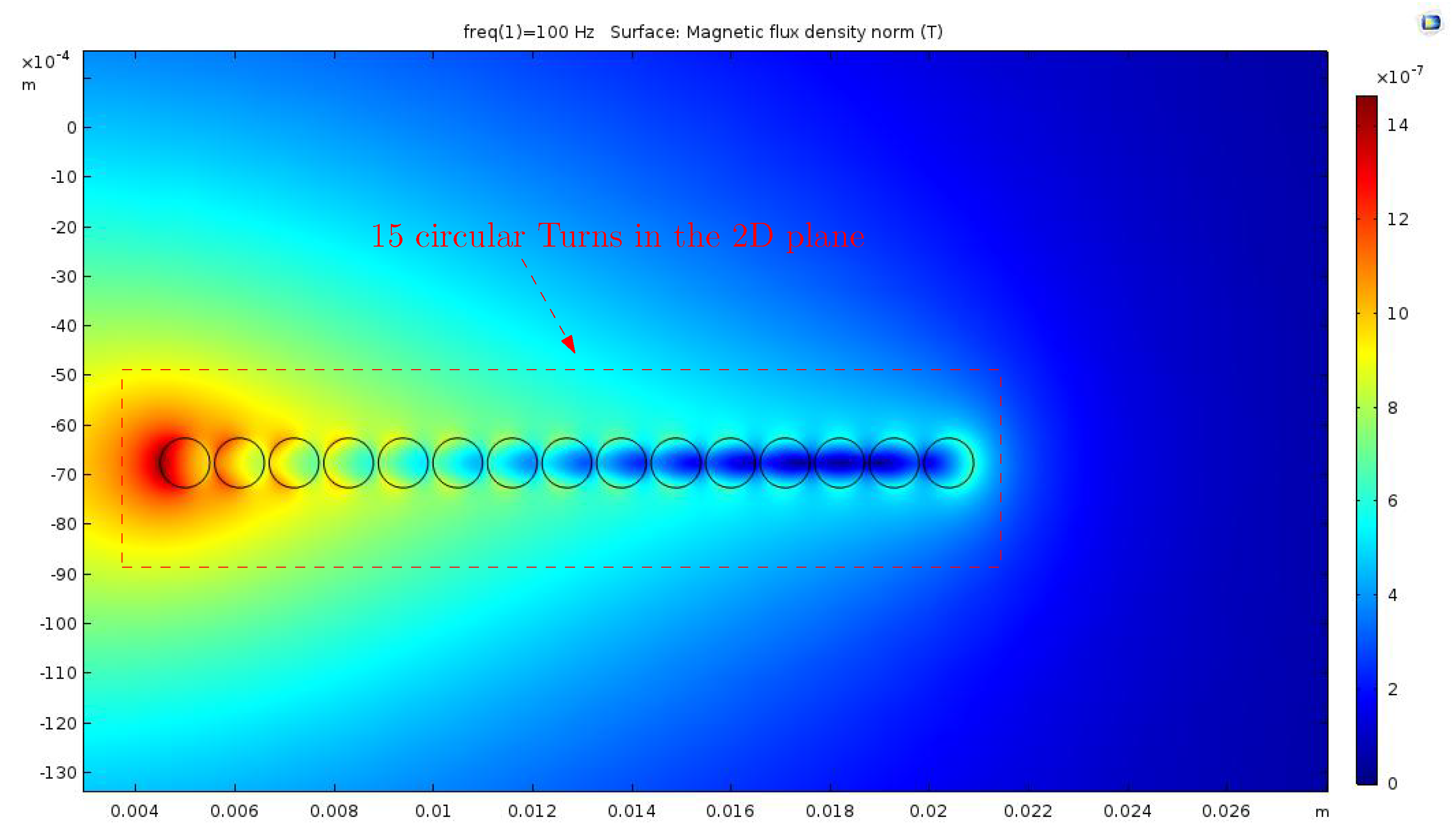
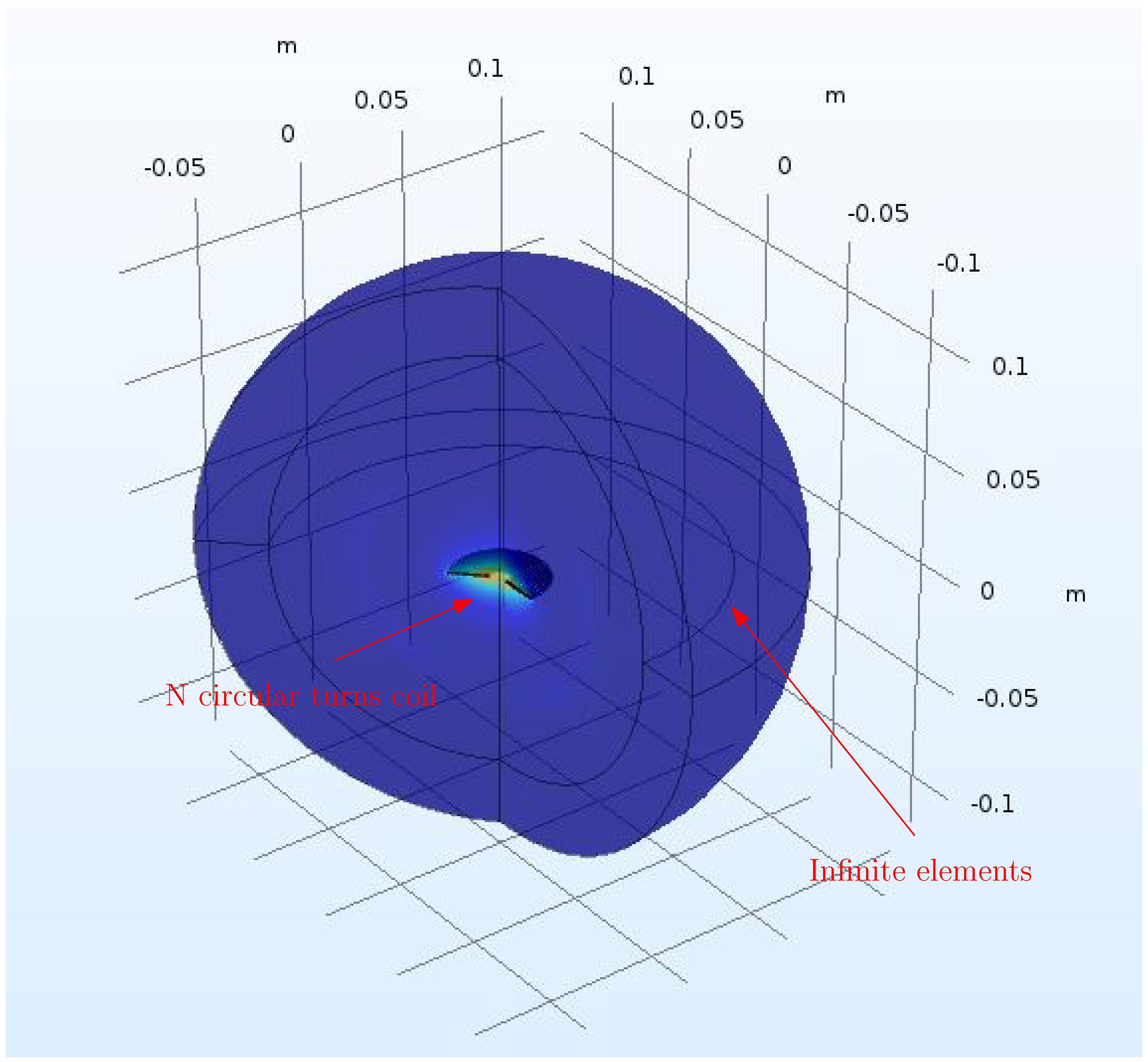
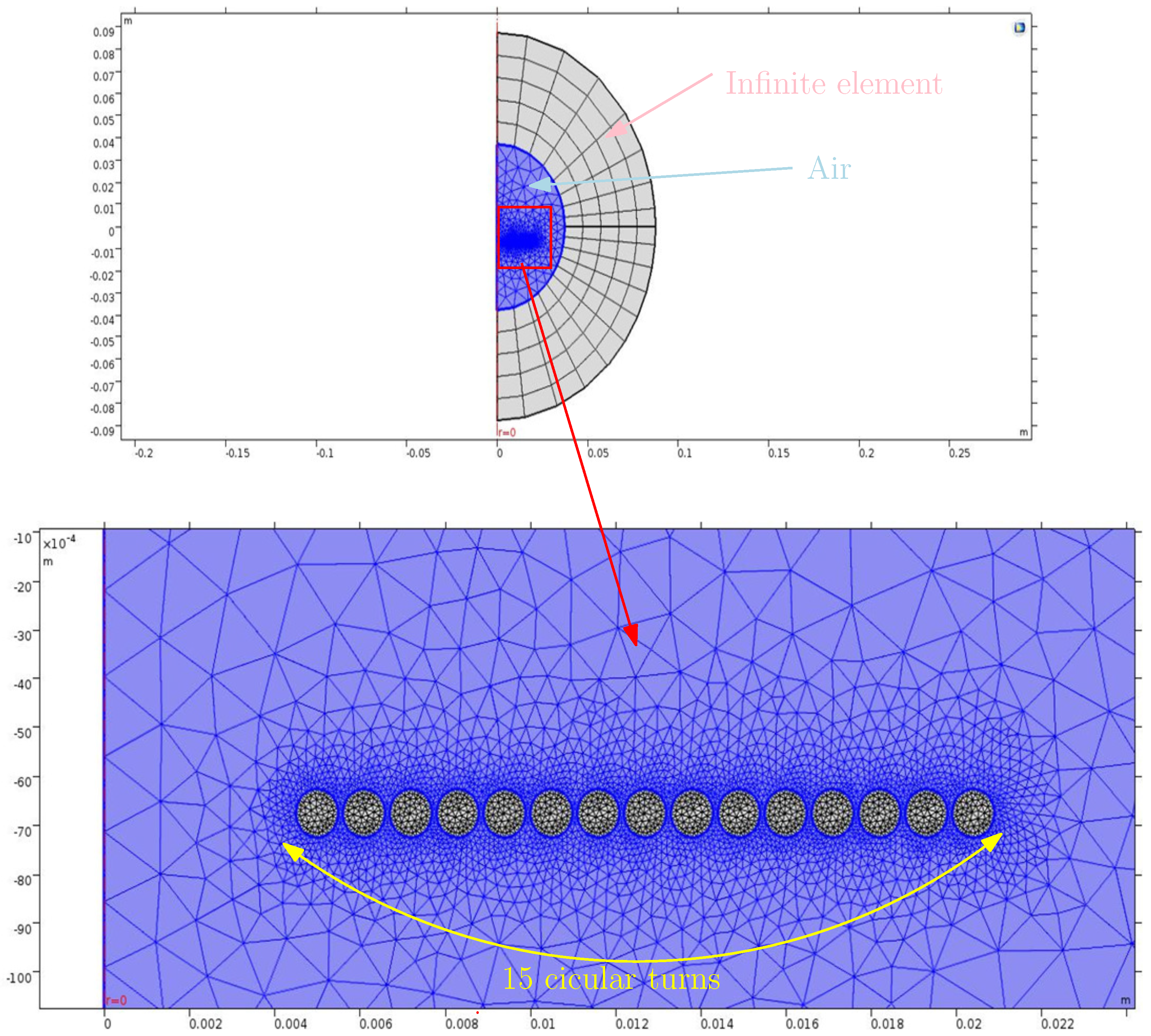
The objective of this work is to optimize the spiral coil quality factor , and we have considered a smart wearable textile as an example of an application. For that, we proposed to approximate the spiral coil shape to N circular turns, as we explained in the previous section. To determine the correctness of the above-mentioned theoretical analysis, this paper adopted the COMSOL software to design the approximated spiral coil to N circular turns. For the designed coil, it yields a skin depth of 0.2 mm. Comparing this to the wire width of 1 mm of the coil shows that we have to model our coil with a single conductor coil model. However, to do this, we need to create a boundary layer mesh, which in 3D, yields a high number of mesh elements. Since we only want to compute the quality factor of the coil, the most effective approach is to create a 2D axis-symmetric model of the coil and approximate it only using its cross-section surfaces. By doing so, we can neglect the influence of the spiral spacing, which is negligible anyway in this case.
Using COMSOL software, we developed an inverse process. We computed the coil inductance
and the coil resistance
. We introduced the results of the spiral coil approximation to the circular coil (the internal radius and the number of turns). In addition, the design constraints, including the frequency, external radius, and material used, were used as inputs. During the design process, we first modeled the coil in the 2D plane, as shown in
Figure 9.
The 15 small circles represent the 15 turns of the coil in the 2D plane. Then, we created the mesh elements, as shown in
Figure 10. Later, we transformed the 2D model into a 3D model, as illustrated in
Figure 11.
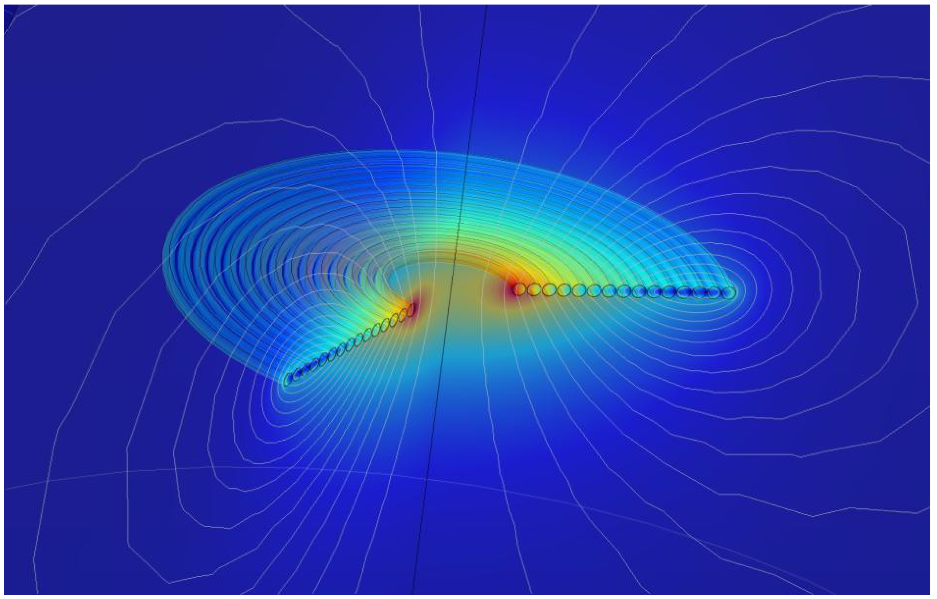
Figure 12 illustrates the
representation of the optimized coil with the magnetic flux lines. The simulation results from COMSOL yielded a coil self-inductance
of
H and a coil internal resistance
equal to
m
. These results were similar to those obtained for the approximated coil without considering the skin effect. In fact, in this case, the COMSOL software neglected the skin effect, which was equal to 0.2 mm.
5. Discussion
A conventional WPT system contains a transmitter coil and a receiver coil. The higher their coil’s quality factor, the higher the mutual inductance; consequently, the PTE is important. In textile applications, the receiver coil design is challenging because it must ensure a compromise between a high coil quality factor, a small form factor, and a comfortable shape.
The purpose of this paper was to optimize the coil geometry in a WPT system, with the aim of improving the coil quality factor (
), which improves the power transfer efficiency. We considered smart textile wearable devices as the application. In wearable applications, the receiver coil should be comfortable and flexible for users. For this important reason, the commercial Litz coil (high performance (low resistivity) compared to PCB coils) could not be utilized on the receiver side. A textile coil appears to be a convenient alternative in such systems. The coil shape selected in this paper is a flat spiral coil since it exhibits better tolerance to the coil’s misalignment. The material used is also an important parameter in the coil design. Considering that we are aiming to increase coil efficiency, we opted for silver as the material because it has low resistivity (it is a good conductor).
Table 3 shows a comparison of the spiral (exact model) and circular (optimized) coil shapes, considering the skin depth.
Using preformed coils is mandatory for reaching a high PTE in a WPT system. In this work, we validated the approximation of the spiral coil shape to
N circular turns instead of the exact model. For better precision and to verify this method, we modeled the approximated coil using the COMSOL software. The overall results are presented in
Table 3. The exact model achieved a coil quality factor of
, and the approximated model achieved a coil quality factor of
, with a relative deviation of around 4.4%. The coil modeled using COMSOL achieved a coil quality factor of
. Based on the research carried out on the spiral coil approximation to
N circular turns, it is possible to conclude that this method makes the coil design simpler and better for the coil designer without modifying the coil inductance (
), which determines the magnetic field between coils. Based on the simulation results in COMSOL, it can be concluded that the proposed model has been validated.
6. Conclusions
Ensuring a high wireless PTE strongly depends on the quality factor of the coils used. This parameter (the coil quality factor) is very sensitive to the coil geometric parameters, such as the number of turns (N), the spacing between lines (s), the wire width (), the frequency, the internal radius, the external radius, and the material used. To reach the highest Q, the aforementioned parameters must be at their optimum values.
In this work, we first used a mathematical model for the spiral coil shape to calculate its length and resistance in terms of the internal radius, external radius, spacing, number of turns, wire width, and conductivity. Next, we approximated the spiral model with a circular model to simplify the computation of the wire length and its resistance. Then, we compared the two coil length calculation methods for different IPT system properties. Later, we validated the model using COMSOL software. The main objective of this comparison was to validate the circular shape approximation within certain geometric parameters. This allows coil designers to choose the appropriate parameters to achieve the highest possible coil quality factor for their application. In this work, we used a smart textile device as a specific application, operating at a frequency of 1 kHz to adhere to Qi guidelines (Chinese organization). The results obtained showed a deviation of around 4% in terms of the coil quality factor within a predetermined range of coil parameters. The developed approximation is valid for wire widths smaller than 1 mm. This flexible coil provides a convenient and comfortable option for integrating resonant inductive wireless power transfer and smart technologies into clothing, which is more comfortable compared to rigid technologies. It is important to mention that the COMSOL simulation was not 100% accurate. Consequently, further development of this work will consist of implementing a complete wireless power transfer system for a textile application according to the Qi guidelines (frequency 1 kHz).


