Abstract
This paper presents results from a physical and numerical study of a new type of axial hydraulic turbine with oscillating blades, which is used to utilize wind waves energy. The pilot studies were conducted on a test bench constructed in one of the labs of the “Department of Hydrodynamics and Hydraulic Machines” in the Technical University of Sofia. The numerical computations were performed with the commercial software package Ansys Fluent 2022. The flow has been modeled with the k-ω (SST) turbulence model, whose main advantage is to resolve the viscous sublayer in over refined meshes. A pressure-based solver was used since the fluid is incompressible and the flow velocity is low. The study investigated several different pitch angles of the blades ranging between 0 and 80 deg at prescribed upstream flow velocities from 0.15 m/s to 2.0 m/s. The dependencies of the torque coefficient, power coefficient, and the optimal tip speed ratio on the flow velocity are presented and discussed.
1. Introduction
Sea wind waves are an important renewable energy source, as they show large energy resources in vast geographical areas. According to the current state of the art, it is estimated that ocean waves have the capacity to generate a substantial two terawatt-hours (TWh) of energy annually worldwide [1,2]. The development of wave energy converters (WECs) has been an ongoing endeavor for many years, resulting in a variety of device models and sizes. However, this diversity often translates into expensive and complex processes, especially for larger and more sophisticated WECs.
Interestingly, unlike some other renewable energy sources like wind power, where increasing energy output can be achieved by expanding the swept area, WECs face limitations when it comes to enhancing energy generation. Only a limited number of WECs have demonstrated the capability to effectively improve their energy output, as discussed in [3,4]. This limitation stems from the fact that WECs tend to have an optimal size from the early stages of development, making significant further advancements challenging [1,2,5,6,7].
Coastal power plants more often use water chambers, in which crushing sea waves periodically change the water column level. The energy of the oscillating water column can be harnessed with low head turbines. Axial bi-directional turbines are the most popular. The blade cascade of these turbines works on the principle of the lift force. It has hydrodynamically shaped, symmetrical-profiled blades that can maintain the runner’s rotational direction when the axial flow reverses. A typical example is the Wells turbine, which is one of the most used turbines for utilizing the kinetic energy of reversing axial flows. Wells is a low-pressure air turbine used to absorb the kinetic energy of the incoming airflow, injected into the chamber by the oscillating water column. The main disadvantage of the Wells turbine is the low starting torque. Incoming waves push the airflow into the chamber through the turbine with different intensities and amplitudes. The acceleration and velocity of the incoming flow will differ. Despite its good efficiency, the Wells turbine will not produce sufficient electric power due to the inability to self-start at too-low flow velocities.
The water turbine with oscillating blades (WTOB) is a new type of water turbine invented at the Technical University of Sofia. A characteristic feature of this turbine is that it is subjected to variable axial hydraulic flow. This forces the working blades to oscillate around their longitudinal axis. The hydraulic pressure, as a force, is applied at the static center of the blade. This force creates a variable moment around the longitudinal axis of the blade. This moment is balanced by a moment created by a spring force applied to the oscillating blade. The considered WTOB is still in the process of research, testing, and improvement of the construction. WTOB is designed to harness kinetic energy directly from the motion of the sea waves. It can be utilized in coastal power plants or submerged in the sea. This new type of axial turbine works with higher efficiency due to the movable blades that can occupy an optimal pitch angle in relation to the turbine’s rotational speed and flow velocity. Figure 1 shows the scheme of the turbine’s runner. The oscillating blades (4) are attached to the hub (1) via water-lubricated sliding bearings (2). The blades are positioned at a specific pitch angle (at which they generate high starting torque) and fixed at the upper end by mechanical tension springs (17) to the axis (18) via cranks (6) and bolts (5). A fairing (12) is mounted to the hub via studs (7) and nuts (8 and 9). The lower end of the springs are attached to the plate (11). When the water column rises, the flow passes through the runner and accelerates the turbine. When the water column starts to fall down, the hydrostatic pressure and peripheral forces push the blades against the rotor plane at a specific pitch angle (maintained by the springs) at which the turbine works with maximum efficiency. Thus, the presented scheme combines two different runners that mutually eliminates their disadvantages. The first one has high starting torque and low efficiency; the second one has low starting torque and high efficiency. Moreover, considering the density of the salt water (which is about 875 times bigger than that of the air), the hydraulic turbine with oscillating blades should provide much more electric power than the Wells turbine. A 3D model of the turbine is presented in Figure 2. The design of the blades, which can oscillate around their horizontal axis, allows the conversion of the vertical motion of the seawater relative to the impeller into a unidirectional rotary motion of the vertically located turbine shaft. The expected mechanical efficiency of the turbine is 35%. Although this turbine is intended to operate with a vertical shaft, it is possible, after minor design changes, to operate stably with an inclined and even a horizontal shaft. It can be used as a subsystem for converting sea wave energy into rotary motion in wave energy conversion (WEC) machines that use different concepts [8,9,10]. To utilize the present concept, it is planned to use a buoy on the water surface to which the blade wheel shall be attached with a Cardan shaft or some other type of universal joint.
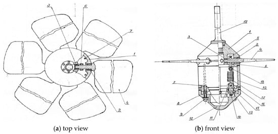
Figure 1.
Scheme of WTOB: 1—hub, 2 and 3—sliding bearings, 4—blades, 5—bolts, 6—cranks, 7—studs, 8 and 9—nuts, 10—cylindrical corpus, 11—plate, 12—fairing, 13—pin, 14—supporting washer, 15—washer, 16—pin, 17—tension springs, 18—axis, 19—shaft.
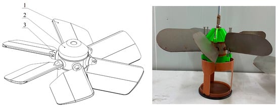
Figure 2.
Three-dimensional model and picture of the hydraulic turbine: 1—blades, 2—fairing, 3—forks.
2. Test Bench
The first pilot physical study of the hydraulic turbine with oscillating blades is conducted on the test bench, shown in Figure 3. The illustrated components are as follows: 1—hydraulic motor, 2—crank (through which the amplitude of the wave is determined), 3—supporting frame, 4—scale for load settings on the turbine, 5—flywheel, 6—RPM sensor, 7 and 9—couplers, 8—torque meter, 10—cardan coupling (which moves the runner smoothly along the three axis), 11—turbine shaft, 12—supporting frame. The driving mechanism of the turbine consists of a hydraulic motor, eccentric pulley, mobile platform, and steel rope. The hydraulic motor rotates the pulley and simulates sea wave motion by moving the turbine’s runner in a vertical direction. To conduct the experiment, it is essential to affix the following measuring devices to the stand. These instruments will measure the specific quantities and parameters required for our research.
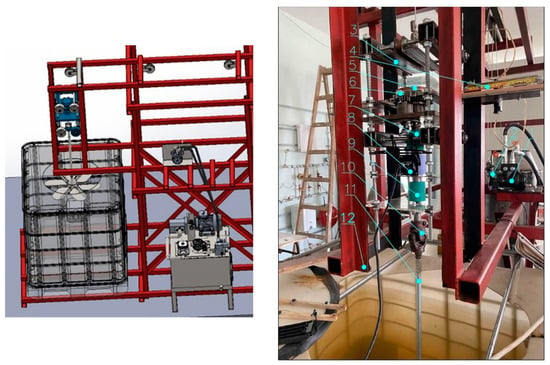
Figure 3.
Three-dimensional model and picture of the test bench: 1—hydraulic motor, 2—crank, 3—supporting frame, 4—scale for loading settings on the turbine, 5—flywheel, 6—RPM sensor, 7 and 9—couplers, 8—torque meter, 10—cardan coupling, 11—turbine shaft, 12—supporting frame.
A shaft speed sensor, often referred to as a wave frequency or amplitude sensor, is installed on the drive shaft of the hydraulic motor. A digital tachometer is connected to the turbine’s shaft to monitor and record its rotational speed or revolutions. The torque of the turbine’s shaft is measured by a digital torque sensor.
The test bench is located in one of the labs of the Department of “Hydroaerodynamics and Hydraulic Machines” at the Technical University of Sofia. The aim of the experiment is to test the functionality of the water turbine runner with oscillating blades and to collect some preliminary data about it. The operational range at various wave levels extends from −90 deg to 90 deg. In order to obtain the influence of the blade’s pitch angle on the turbine’s power, experiments are conducted with fixed pitch angles.
3. Results from the Pilot Physical Study
Results from the conducted physical experiments are presented in Table 1 and Figure 4 in dimensionless form for pitch angles φr = 20, 25, 30, and 35 deg. Every test is conducted following the subsequent procedure: (1) Activate the hydraulic system. (2) Adjust the revolutions of the hydraulic motor to the desired value as per our requirements. (3) Commence measuring the revolutions of the turbine shaft following the adjustment. (4) Display and monitor the torque measurement on the torque meter. (5) The load (brake) applied to the turbine can be modified; for this test, it is configured to a specific load as per our requirements. (6) When needed, the amplitude of the wave can be adjusted using the crank.

Table 1.
Results from the conducted physical study.
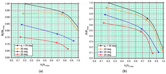
Figure 4.
Performance characteristics of the turbine at different pitch angles of the blades. (a) Mt/Mt max = f(nt/nt max). (b) P/Pmax = f(nt/nt max).
According to the data from the pilot studies, rotational speed, power, and torque increase with the pitch angle of the blades φr. In order to reduce the number of further physical experiments and to obtain a more detailed picture of the efficiency of the turbine, the Department of “Hydroaerodynamics and Hydraulic Machines” has developed a numerical computational model, described in Section 4, based on the finite element method.
4. Details of the Numerical Computational Model
The present numerical model aims to improve the results obtained from previous numerical investigations of WTOB and to provide more information about its efficiency and estimated dependences for the main parameters of such a turbine [11]. The results from the current study will be used for the final design of the WTOB.
To overcome the difficulties related to the computational mesh, these earlier investigations made considerable compromises regarding the geometry of the turbine wheel and the computational domain size. The mesh density around the blades was decided based on the possibilities of the available hardware and the restrictions on the simulation time. Computational fluid dynamics (CFD) can be successfully applied to determine integral performance characteristics for different turbines. This allows for conducting in-depth analysis without physically changing the geometry of the turbine. Figure 5 presents the geometry of the turbine wheel of the studied hydraulic turbine. The goal of the study is to determine the effective power using several operating modes at fixed blade angles (measured between the blade chord and the plane of rotation) of φr = 0, 10, 15, 20, 25, 30, 50, 60, and 80 deg and a constant upstream velocity Cw = 0.15, 0.25, 0.5, 1.0, and 2.0 m/s. The turbine wheel, with an external diameter of D1 = 500 mm, consists of 6 profiled blades (1) with height H = 180 mm [4]. The chord of the airfoil is l = 130 mm and the maximum thickness is δ = 7.5 mm. The blades are attached to a hub (2) with forks (3), which can rotate around their axis.
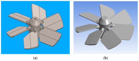
Figure 5.
Three-dimensional model of a hydrokinetic turbine blade wheel. (a) Original design. (b) Simplified design.
The methodology used to mesh the turbine wheel requires removing the openings and fixtures from the construction and filling in the cavities of the blades (Figure 5). To calculate the torque of the turbine, the Multiple Frame of Reference method (MFR) and the sliding mesh technique were used. The K-omega SST [12] turbulence model was chosen due to its better accuracy when resolving boundary layer flow. Several characteristics for different values of the upstream flow velocity Cw in the range 0.1 ÷ 2 m/s are calculated.
The geometry and computational domain, as well as the assigned boundary conditions, are shown in Figure 6. The domain is subdivided into two regions. The first has the shape of a cube and contains the outer flow region. The second, with the shape of a cylinder with a radius of 380 mm and a height of 400 mm, contains the turbine blade wheel. The assigned boundary conditions are velocity at the inlet, outflow from the outlet (which fixes the gradient of flow variables to zero), and smooth walls for the other surfaces of the domain where the viscous friction at the walls is evaluated. The computational data are exchanged between the two regions through a so-called interface, which represents the contact surface along which the rotating together with the turbine wheel cylindrical region slides.
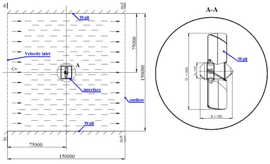
Figure 6.
Overall dimensions of the computational domain and assigned boundary conditions.
The geometrical properties of the meshes, corresponding to the two regions, are shown in Table 2.

Table 2.
Computational grid properties.
Mesh is presented in Figure 7. The influence of the mesh refinement (of the dimensionless wall distance y+ [13]) over the torque is determined by changing the wall distance of the first layer of blade cells in the range 10–2000 μm. Calculations are performed using the iterative procedure of Gauss–Seidel [14] of the discretized partial differential equations of Navier–Stokes [15] closed mathematically with the k-ω turbulence model:
where μt (Pa.s) and υt (m2/s) are the dynamic and kinematic eddy viscosity; u is the time-averaged velocity (m/s); ρ is the density of salty water equal to 1025 kg/m3; K is the turbulent kinetic energy (J/kg); ω is the specific turbulent energy dissipation rate (1/s); µ is the dynamic viscosity of the fluid (Pa.s); t is the time; and xi is the space coordinate (m). Indices “i” and “j” refer to the vectors of the Cartesian coordinate system (X, Y, Z); B1 is a linear function, which converts the k-ϖ SST turbulence model into a k-ε turbulence model outside of the boundary layer region; ξτw, ξβ, ξk, ξω, and ξω2 are constants. The computations were performed on Ansys Fluent 2022 commercial software package. A pressure-based solver was used since the fluid is incompressible and the flow velocity is low.
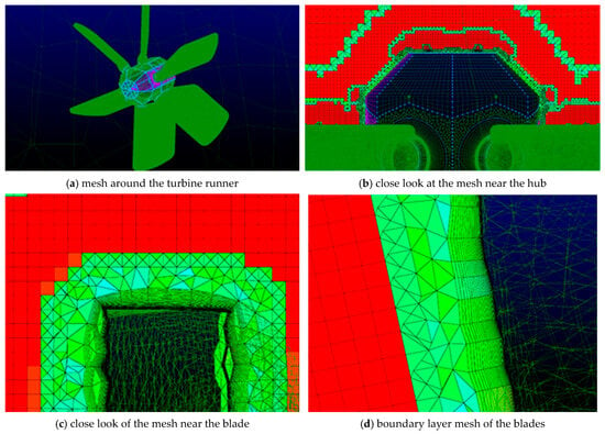
Figure 7.
Computational mesh around the contour of the turbine’s runner.
The numerical setup calculates the detachment of the boundary layer from the turbine blades with better accuracy and removes, to a great extent, the influence of the outer region on the flow parameters through the blade wheel.
5. Results and Discussion
The influence of the mesh on the operational characteristics of the turbine at an upstream velocity of Cw = 2 m/s is presented in Figure 8 and Table 3. According to the data, a decrease in y+ under 9.5 does not significantly affect the results; so, this value can be viewed as a threshold in the grid sensitivity study and, thus, the corresponding mesh is further used for numerical computations. The torque exerted on the blade wheel was calculated at the end of computation by integrating the vector product of force and position vector for all cell faces that constitute the blade wheel surface. The power was then obtained by multiplying the torque by the blade rotational speed. The maximum discrepancy in the torque and power are 3 Nm and 6 W, respectively, at an angular speed of 20 min−1. The increase in y+ to 180 enhances the torque (resp. the power) with the decrease in angular speed n. The maximum discrepancies are 19.5 Nm at 10 min−1 (Figure 5a) and 8.1 W at 30 min−1 (Figure 5b). Further coarsening of the mesh around the blades (y+ = 350) does not lead to a noticeable change in the characteristics.
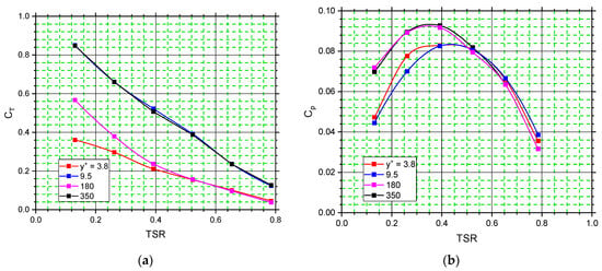
Figure 8.
Performance characteristics of the turbine at different mesh densities. The values refer to blade’s pitch angle φr = 60 deg. (a) CT = f(TSR). (b) CP = f(TSR).

Table 3.
Computed values of power and torque of the turbine wheel at different mesh densities.
Figure 9 and Figure 10 show the distribution of dimensionless velocity and pressure along the blade wheel at an upstream velocity of 2 m/s in two streamwise planes, one of them coincident with the blade leading edge. It is seen that the maximum velocity pertains to the leading edge of the blades. This is because of the local increase in the velocity due to the formation of vortices from flow separation. The flow velocity around the runner is uniform. The velocity matches the far-field velocity because the surrounding walls have no effect on the flow parameters, which would affect the operating characteristics of the turbine.

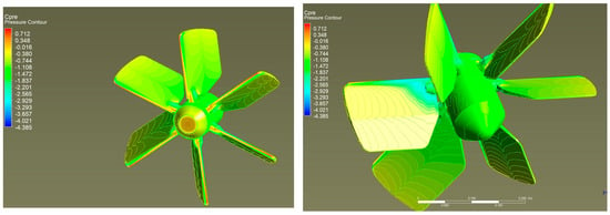
Figure 9.
Velocity magnitude and pressure distribution through the hydrokinetic turbine at pitch blade angle φr = 80 deg.
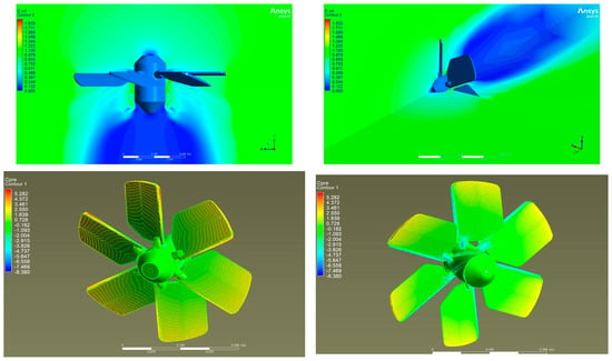
Figure 10.
Velocity magnitude and pressure distribution through the hydrokinetic turbine at pitch blade angle φr = 20 deg.
Figure 11 and Table 4 show the effect of the flow velocity on the torque coefficient, maximal power coefficient, and optimal tip speed ratio at different flow velocities and pitch angles of the blades. The calculations are performed for upstream flow velocities of 0.15 m/s, 0.25 m/s, 0.5 m/s, 1 m/s, and 2 m/s. The relationship resembles a straight line between values:

Figure 11.
The impact of the flow velocity and blade’s pitch angle (a) on the torque, (b) on the power, and (c) at y+ = 9.5.

Table 4.
Computed values of torque, maximum power, and optimal angular velocity at different upstream flow velocities and pitch angles of the blades.
- CT = 0.377 ÷ 0.387 and Cp = 0.074 ÷ 0.083 at φr = 60 deg;
- CT = 0.308 ÷ 0.318 and Cp = 0.231 ÷ 0.239 at φr = 30 deg;
- CT = 0.288 ÷ 0.298 and Cp = 0.250 ÷ 0.268 at φr = 25 deg;
- CT = 0.238 ÷ 0.248 and Cp = 0.272 ÷ 0.280 at φr = 20 deg;
- CT = 0.189 ÷ 0.199 and Cp = 0.260 ÷ 0.272 at φr = 15 deg;
- CT = 0.109 ÷ 0.119 and Cp = 0.231 ÷ 0.239 at φr = 10 deg.
Figure 12 presents the dependence of the maximum power and torque on the blade’s pitch angle at the studied flow velocity interval.
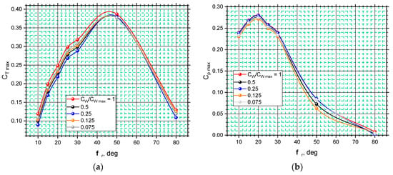
Figure 12.
Dependence of the max torque (a) and power on the blade’s pitch angle (b) at flow velocity. (a) Max torque coefficient. (b) Max power coefficient.
Changing the blade’s pitch angle has a significant effect on the efficiency and self-starting capability of the wheel. At φr = 50 deg, the turbine rotates with lower power and the highest torque, making it easier to operate under alternating flow conditions. This is due to the streamlined surface of the blades, their shape, and the relative flow velocity W. With an increase in φr from 0 to 50 deg, the blades are oriented with their leading edge to the flow, which results in a decrease in the drag force FD (which is collinear to the W), an increase in the lift force vector FL (which is perpendicular to FD and W), and its shift to the peripheral velocity vector of the wheel U. The torque of the turbine increases. At φr > 50 deg, the working frontal area of the blades perpendicular to the flow is reduced, which adversely affects the lifting force and the wheel’s torque. The highest power is achieved at pitch angle φr = 20 deg. The blade cascade works with less peripheral resistance at smaller values of φr, which allows the reaching of higher values of the angular speed. The obtained results can be used for an indicative assessment of the efficiency of the blade cascade.
6. Discussion
The presented results are a sample of the performed calculations. Around 200 calculations for analysis of the blade wheel characteristics at different rotational speeds and upstream flow velocities were performed. Each calculation consumed, on average, 10 h of computational time. A substantial number of computational meshes to study the effect of domain size and the mesh density on the calculated performance of the blade wheel were generated. Grid sensitivity analysis was performed to estimate the necessary dimensionless wall distance. The torque and power as a function of the angular velocity of the blade wheel were determined. In addition, the maximum extractable torque and power as a function of the upstream flow velocity were computed as well. It was demonstrated that turbines of this type could be arranged in staggered formation without affecting each other too much.
The estimated dependencies of the torque, power, and the optimal angular speed on the flow velocity can be used for development of an analytical mathematical model, which can describe the interaction of the sea waves with the blade cascade of the hydrokinetic turbine. The power and the absorbed energy can be approximately calculated by assuming that sea waves change the height of the water level in a given section based on sinusoidal law and the maximum speed of the oscillating water column falls within the studied interval (0 ÷ 2 m/s). In future work, the cyclic nature of the sea surface motion will be acknowledged by unsteady inlet conditions.
Author Contributions
Conceptualization, R.V.; methodology, D.M. and M.P.; software, R.I.; validation, G.P. and T.T.; formal analysis, I.S., writing—original draft preparation, R.V. and R.I.; writing—review and editing, I.S. All authors have read and agreed to the published version of the manuscript.
Funding
This research received no external funding.
Data Availability Statement
The data presented in this study are available upon request from the corresponding author.
Acknowledgments
The author/s would like to thank the Research and Development Sector at the Technical University of Sofia for the financial support. The scientific work is performed under the project KΠ06-H37/30 Sea wave energy harvesting by a hybrid system.
Conflicts of Interest
The authors declare no conflict of interest.
References
- Wen, B.; Huang, X.; Li, Y.; Zhang, Y. Utilization of Wave and Wave Energy. In Vibration Utilization Engineering; Springer: Singapore, 2022. [Google Scholar] [CrossRef]
- Chen, Q.M.; Gao, G.Z.; Yue, X.H.; Geng, D.Z.; Xu, L. Hydropower and new energy opportunities and challenges: Advances in wave energy power technology research. Hydropower New Energy 2020, 34, 1–6. [Google Scholar] [CrossRef]
- Velichkova, R.; Simova, I.; Angelova, R.; Markov, D.; Stankov, P.; Denev, I.; Pushkarov, M. Integrated System for Wave Energy Harvesting. In Proceedings of the 2021 6th International Symposium on Environment-Friendly Energies and Applications (EFEA), Sofia, Bulgaria, 24–26 March 2021; pp. 1–4. [Google Scholar] [CrossRef]
- Velichkova, R.; Markov, D.; Simova, I.; Pushkarov, M.; Denev, I. Wave Energy Utilization; Sofia The Net: Sofia, Bulgaria, 2019; ISBN 978-619-91290-2-9. (In Bulgarian) [Google Scholar]
- Zhao, T.; Xu, M.; Xiao, X.; Ma, Y.; Li, Z.; Wang, Z.L. Recent progress in blue energy harvesting for powering distributed sensors in ocean. Nano Energy 2021, 88, 106199. [Google Scholar] [CrossRef]
- Mustapa, M.A.; Yaakob, O.B.; Ahmed, Y.M.; Rheem, C.K.; Koh, K.K.; Adnan, F.A. Wave energy device and breakwater integration: A review. Renew. Sustain. Energy Rev. 2017, 77, 43–58. [Google Scholar] [CrossRef]
- Cheng, Y.; Fu, L.; Dai, S.; Collu, M.; Cui, L.; Yuan, Z.; Incecik, A. Experimental and numerical analysis of a hybrid WEC-breakwater system combining an oscillating water column and an oscillating buoy. Renew. Sustain. Energy Rev. 2022, 169, 112909. [Google Scholar] [CrossRef]
- Velichkova, R.; Markov, D.; Simova, I.; Pushkarov, M.; Angelova, R.; Denev, I. Determination of Operating Parameters of Hybrid System for Wave Energy Utilization. In Proceedings of the International Conference on Electrical, Computer, Communications and Mechatronics Engineering (ICECCME), Maldives, 16–18 November 2022; pp. 1–5. [Google Scholar] [CrossRef]
- Velichkova, R.; Pushkarov, M.; Angelova, R.; Simova, I.; Markov, D.; Denev, I.; Stankov, P. Hydraulic power take off system for wave energy utilization. IOP Conf. Ser. Mater. Sci. Eng. 2021, 1032, 0120302020. [Google Scholar] [CrossRef]
- Velichkova, R.; Markov, D.; Simova, I.; Stankov, P.; Angelova, R.; Zheng, W.; Chen, G. Simulation of water turbine with oscilating blades. In Proceedings of the 7th International Conference on Energy Efficiency and Agricultural Engineering (EE&AE), Ruse, Bulgaria, 12–14 November 2020. [Google Scholar] [CrossRef]
- Simova, I.; Markov, D.; Velichkova, R.; Chen, G.; Wandong, Z. CFD simulation of the interaction between water turbine with oscillating blades runner and sea water under non-regular conditions. In Proceedings of the Scientific Conference EMF’2018, Sozopol, Bulgaria, 17–20 September 2018; pp. 273–278. [Google Scholar]
- CFD Online. Available online: https://www.cfd-online.com/Wiki/SST_k-omega_model (accessed on 1 June 2023).
- Ansys Fluent Theory Guide, Release 18.2. Available online: https://storage.ansys.com/doc_assets/ril_docs/RIL_182.pdf (accessed on 24 May 2023).
- Byjus. Available online: https://byjus.com/maths/iterative-methods-gauss-seidel-and-jacobi/ (accessed on 5 May 2023).
- NASA. Available online: https://www.grc.nasa.gov/www/k-12/airplane/nseqs.html (accessed on 2 February 2023).
Disclaimer/Publisher’s Note: The statements, opinions and data contained in all publications are solely those of the individual author(s) and contributor(s) and not of MDPI and/or the editor(s). MDPI and/or the editor(s) disclaim responsibility for any injury to people or property resulting from any ideas, methods, instructions or products referred to in the content. |
© 2023 by the authors. Licensee MDPI, Basel, Switzerland. This article is an open access article distributed under the terms and conditions of the Creative Commons Attribution (CC BY) license (https://creativecommons.org/licenses/by/4.0/).