
Improving Efficiency of a Pole-Changing Vernier Machine Considering Residual Magnetic Flux Density


Abstract
:1. Introduction
2. Operating Principle and Pole-Changing Process
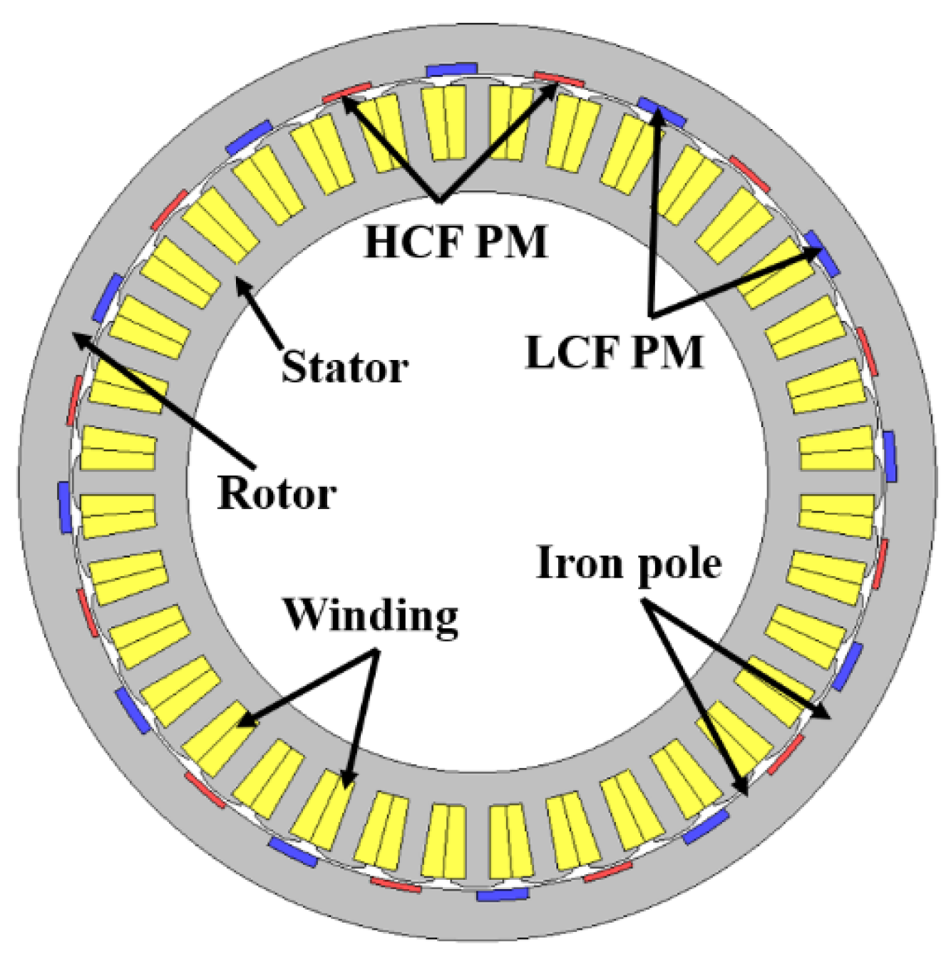
2.1. Structure of PCVM
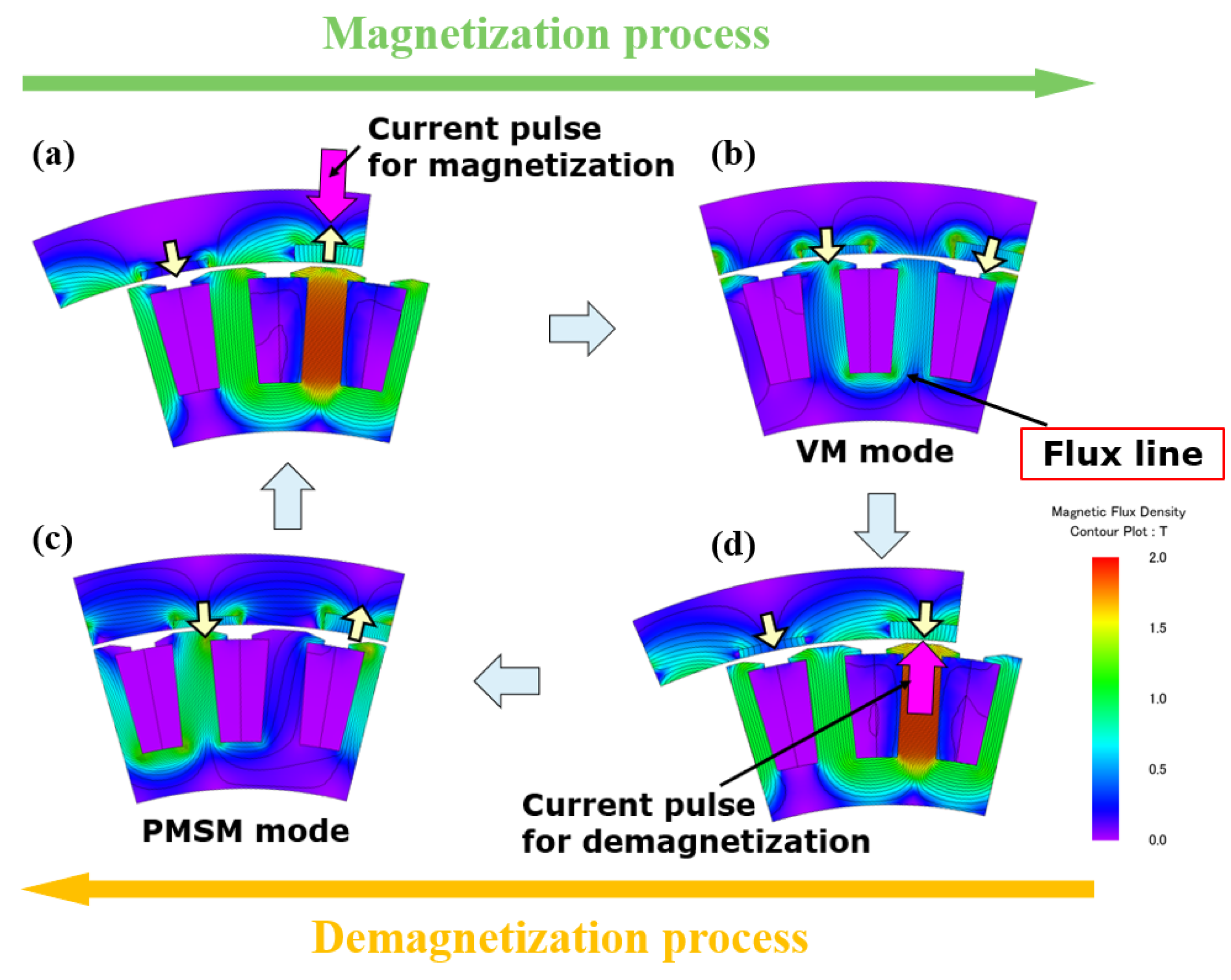
2.2. Operating Principle of Two Modes
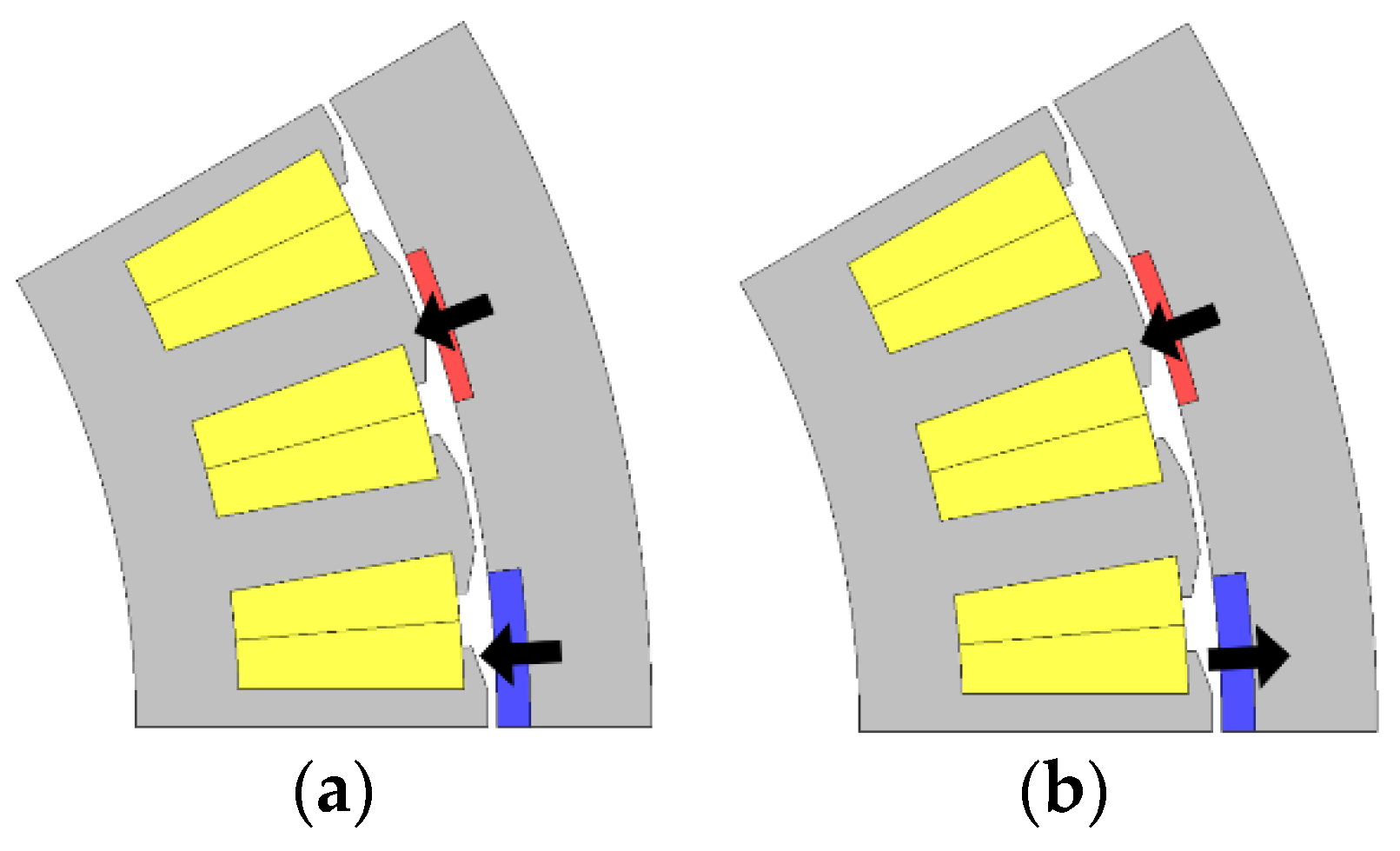
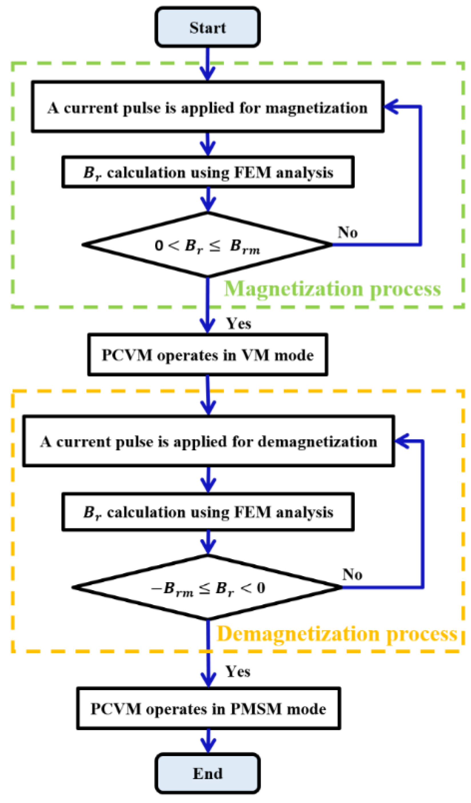
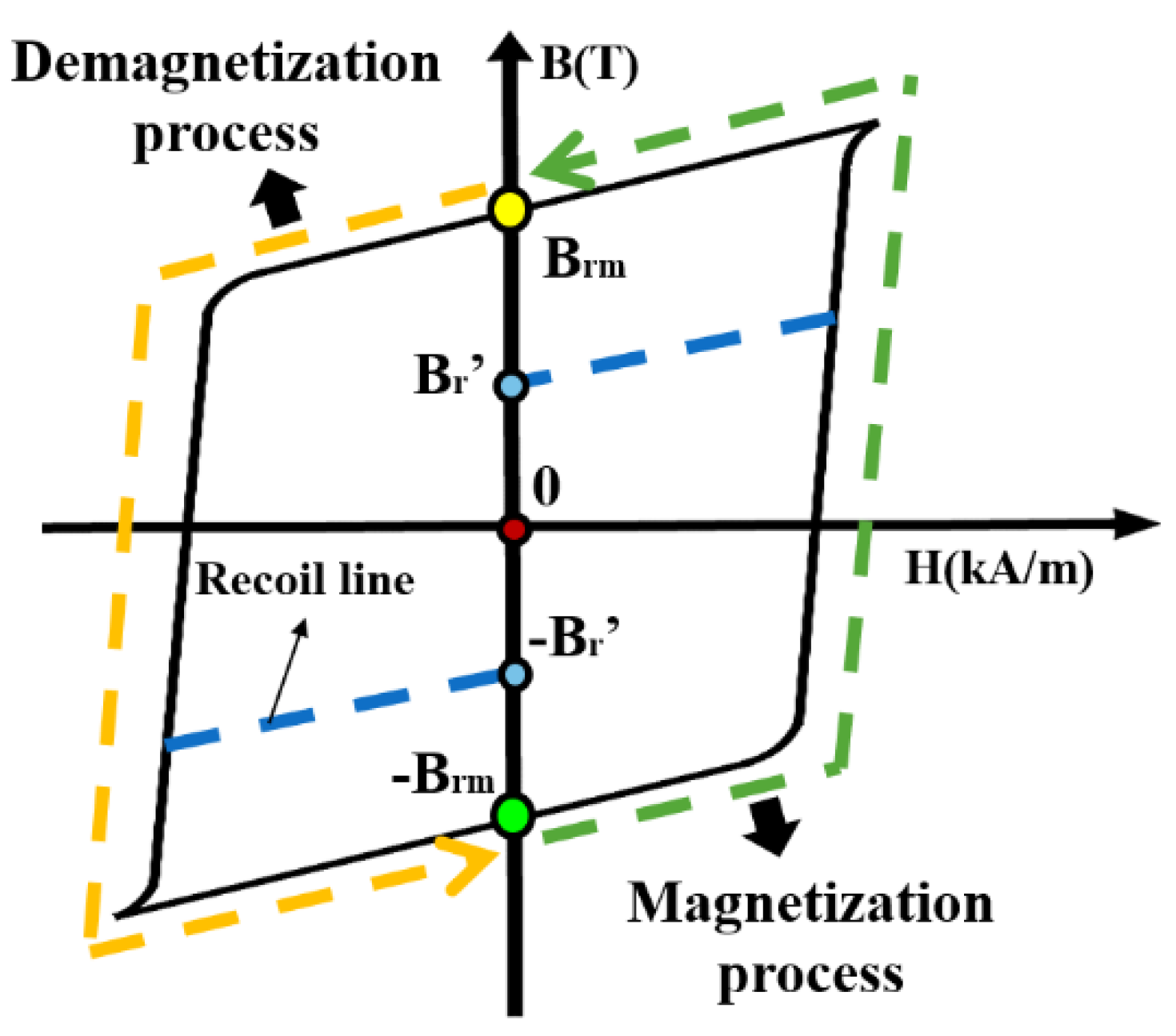
2.3. Pole-Changing Process Using of the LCF PM
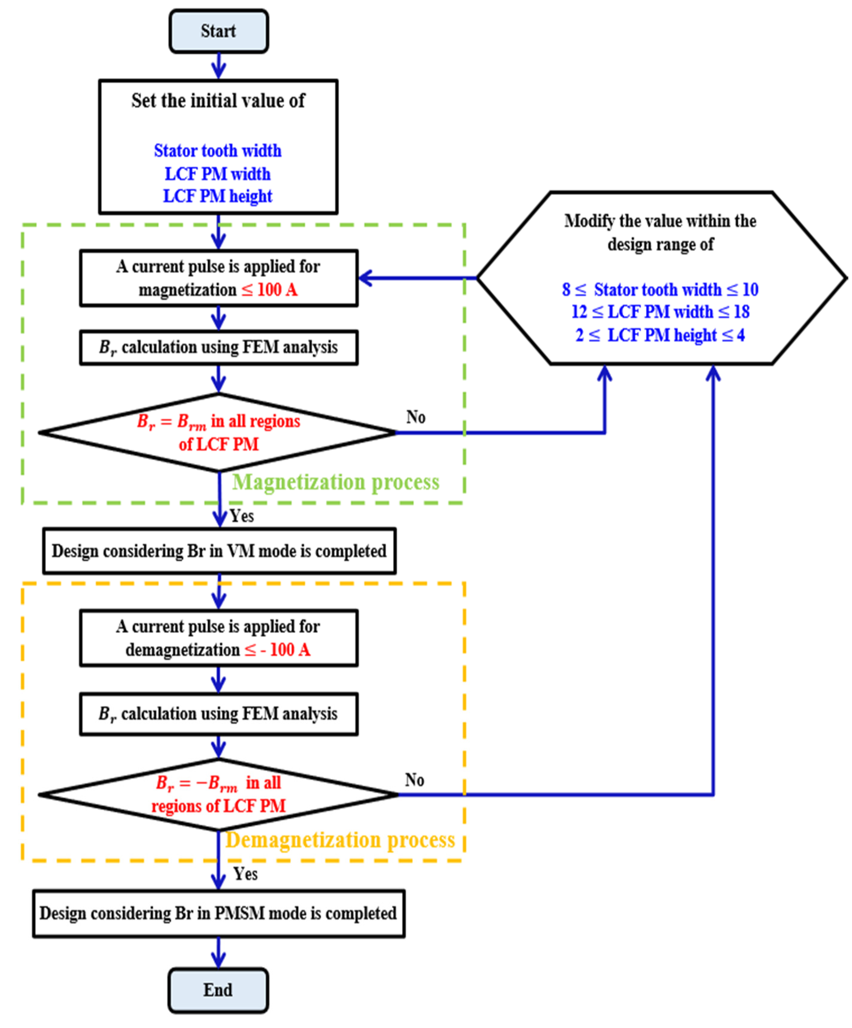
3. Design That Considers of the LCF PM
3.1. Conventional Model without Considering
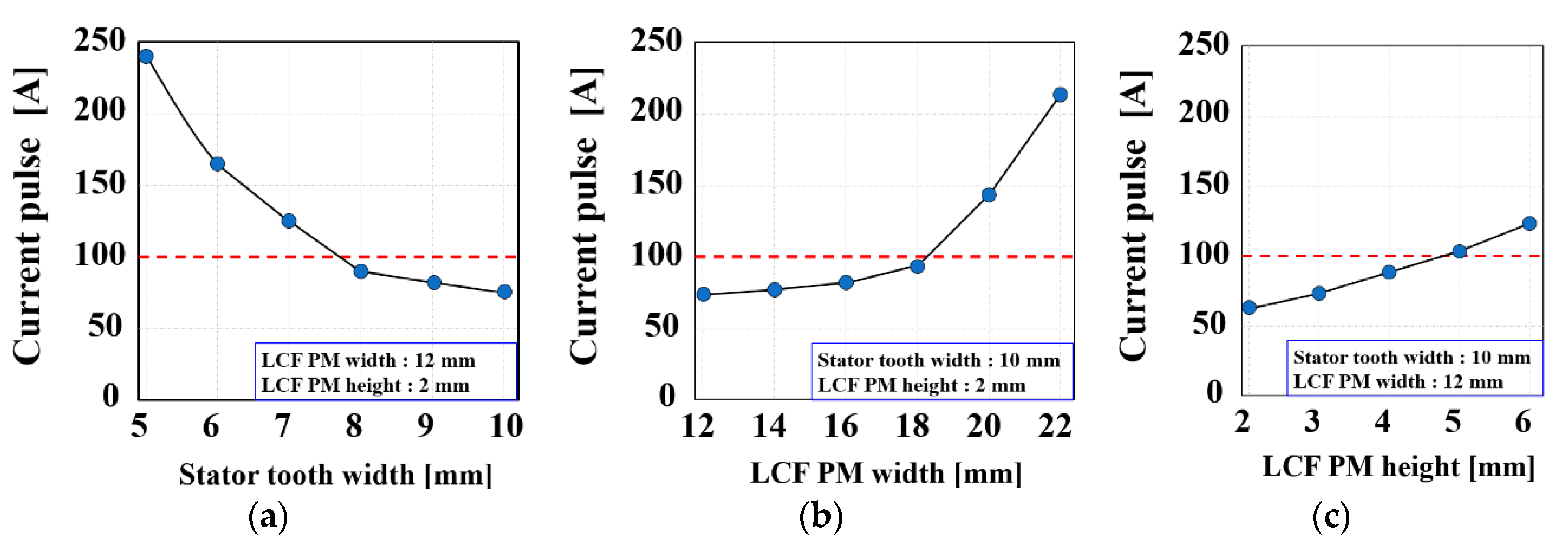
3.2. Selection and Range of Design Parameters
3.3. Determining the Final Values of Design Parameters
4. Performance Evaluation
4.1. Confirmation of with the Pole-Changing Process
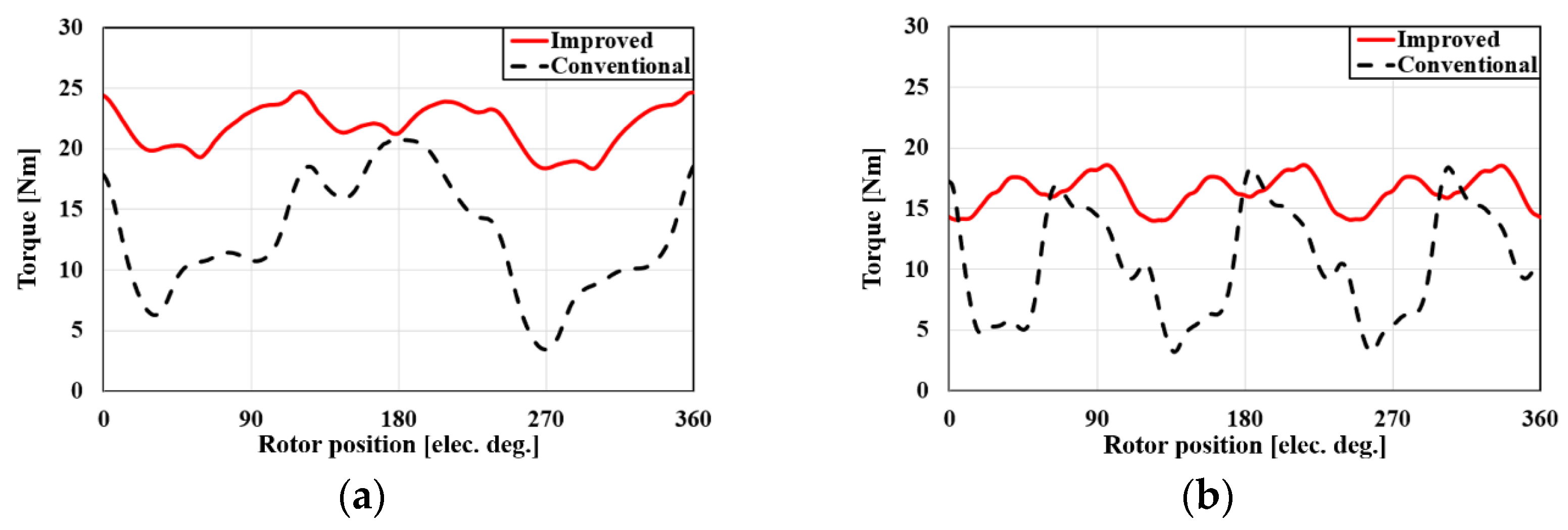
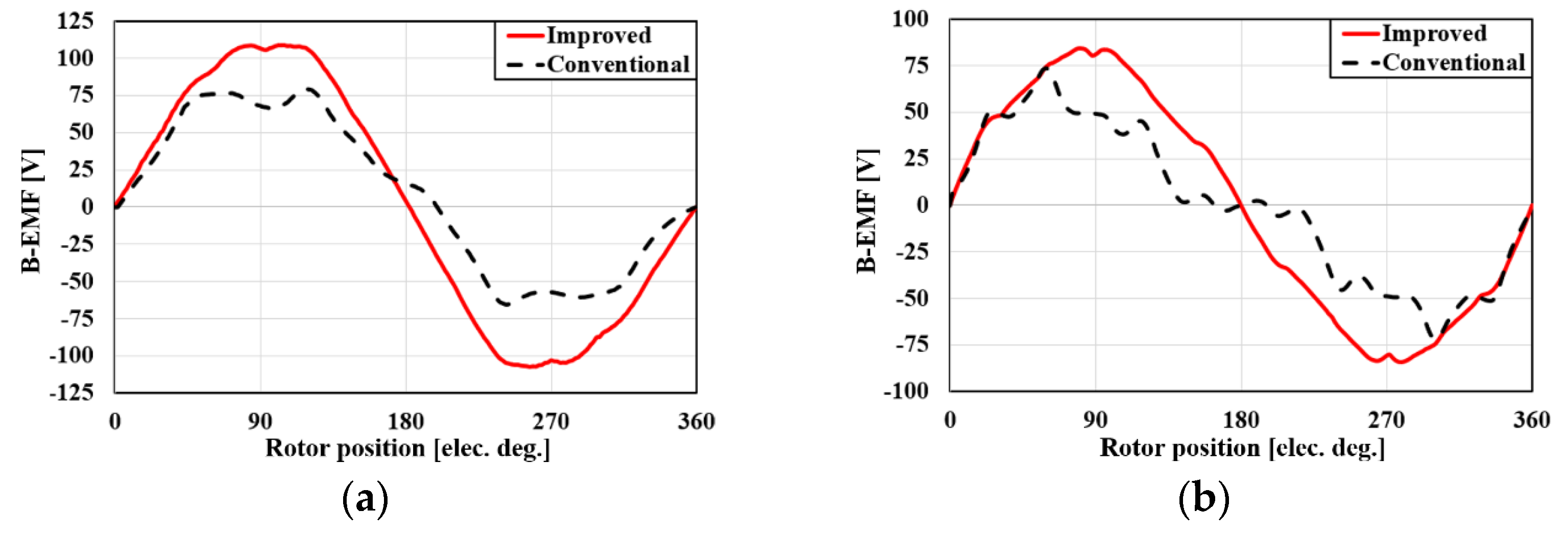
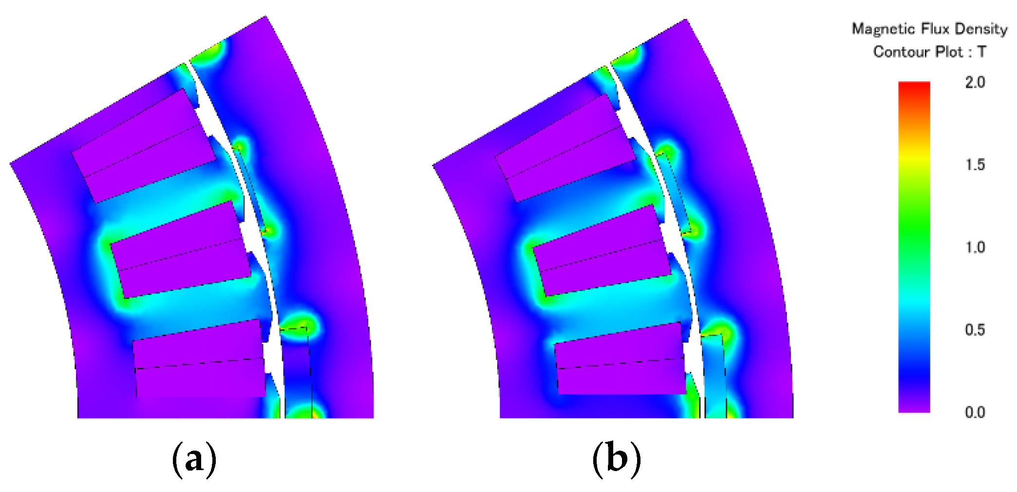
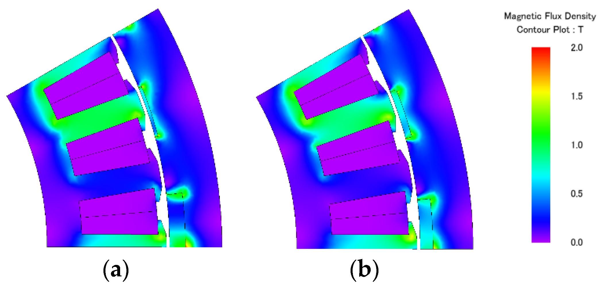
4.2. Comparison of Performances
5. Conclusions
Author Contributions
Funding
Data Availability Statement
Conflicts of Interest
References
- Fang, L.; Jung, J.W.; Hong, J.P.; Lee, J.H. Study on High-Efficiency Performance in Interior Permanent-Magnet Synchronous Motor with Double-Layer PM Design. IEEE Trans. Magn. 2008, 44, 4393–4396. [Google Scholar] [CrossRef]
- Ba, X.; Gong, Z.; Guo, Y.; Zhang, C.; Zhu, J. Development of Equivalent Circuit Models of Permanent Magnet Synchronous Motors Considering Core Loss. Energies 2022, 15, 1995. [Google Scholar] [CrossRef]
- Hou, L.; Ma, J.; Wang, W. Sliding Mode Predictive Current Control of Permanent Magnet Synchronous Motor with Cascaded Variable Rate Sliding Mode Speed Controller. IEEE Access 2022, 10, 33992–34002. [Google Scholar] [CrossRef]
- Tapia, J.; Leonardi, F.; Lipo, T. Consequent-pole permanent-magnet machine with extended field-weakening capability. IEEE Trans. Ind. Appl. 2003, 39, 1704–1709. [Google Scholar] [CrossRef]
- Kwon, J.-W.; Kwon, B.-I. High-Efficiency Dual Output Stator-PM Machine for the Two-Mode Operation of Washing Machines. IEEE Trans. Energy Convers. 2018, 33, 2050–2059. [Google Scholar] [CrossRef]
- Baloch, N.; Kwon, J.-W.; Ayub, M.; Kwon, B.-I. Low-Cost Dual-Mechanical-Port Dual-Excitation Machine for Washing Machine Application. IEEE Access 2019, 7, 87141–87149. [Google Scholar] [CrossRef]
- Toba, A.; Lipo, T.A. Generic torque-maximizing design methodology of surface permanent-magnet vernier machine. IEEE Trans. Ind. Appl. 2000, 36, 1539–1546. [Google Scholar] [CrossRef]
- Kim, B.; Lipo, T.A. Analysis of a PM Vernier Motor with Spoke Structure. IEEE Trans. Ind. Appl. 2015, 52, 217–225. [Google Scholar] [CrossRef]
- Kim, B. Characteristic analysis of a vernier PM motor considering adjustable speed control. In Proceedings of the 2016 IEEE Transportation Electrification Conference and Expo, Asia-Pacific (ITEC Asia-Pacific), Busan, Republic of Korea, 1–4 June 2016; pp. 671–676. [Google Scholar] [CrossRef]
- Zou, T.; Li, D.; Qu, R.; Jiang, D.; Li, J. Advanced High Torque Density PM Vernier Machine with Multiple Working Harmonics. IEEE Trans. Ind. Appl. 2017, 53, 5295–5304. [Google Scholar] [CrossRef]
- Du, K.; Xu, L.; Zhao, W.; Liu, G. Analysis and Design of a Fault-Tolerant Permanent Magnet Vernier Machine with Improved Power Factor. IEEE Trans. Ind. Electron. 2021, 69, 4353–4363. [Google Scholar] [CrossRef]
- Zhao, W.; Sun, X.; Ji, J.; Liu, G. Design and Analysis of New Vernier Permanent-Magnet Machine with Improved Torque Capability. IEEE Trans. Appl. Supercond. 2016, 26, 1–5. [Google Scholar] [CrossRef]
- Xu, L.; Zhao, W.; Liu, G.; Song, C. Design Optimization of a Spoke-Type Permanent-Magnet Vernier Machine for Torque Density and Power Factor Improvement. IEEE Trans. Veh. Technol. 2019, 68, 3446–3456. [Google Scholar] [CrossRef]
- Wang, H.; Fang, S.; Yang, H.; Lin, H.; Li, Y.; Qin, L.; Zhou, Y. Loss Calculation and Temperature Field Analysis of Consequent-Pole Hybrid Excited Vernier Machine. IEEE Trans. Magn. 2017, 53, 1–5. [Google Scholar] [CrossRef]
- Zhao, F.; Kim, M.-S.; Kwon, B.-I.; Baek, J.-H. A Small Axial-Flux Vernier Machine with Ring-Type Magnets for the Auto-Focusing Lens Drive System. IEEE Trans. Magn. 2016, 52, 1–4. [Google Scholar] [CrossRef]
- Ostovic, V. Memory motors-a new class of controllable flux PM machines for a true wide speed operation. In Proceedings of the Conference Record of the 2001 IEEE Industry Applications Conference. 36th IAS Annual Meeting (Cat. No.01CH37248), Chicago, IL, USA, 30 September–4 October 2002; Volume 4, pp. 2577–2584. [Google Scholar] [CrossRef]
- Ostovic, V. Pole-changing permanent-magnet machines. IEEE Trans. Ind. Appl. 2002, 38, 1493–1499. [Google Scholar] [CrossRef]
- Yang, H.; Zhu, Z.Q.; Lin, H.; Wu, D.; Hua, H.; Fang, S.; Huang, Y.-K. Novel High-Performance Switched Flux Hybrid Magnet Memory Machines with Reduced Rare-Earth Magnets. IEEE Trans. Ind. Appl. 2016, 52, 3901–3915. [Google Scholar] [CrossRef]
- Yang, H.; Zheng, H.; Lin, H.; Zhu, Z.-Q.; Fu, W.; Liu, W.; Lei, J.; Lyu, S. Investigation of Hybrid-Magnet-Circuit Variable Flux Memory Machines with Different Hybrid Magnet Configurations. IEEE Trans. Ind. Appl. 2020, 57, 340–351. [Google Scholar] [CrossRef]
- Baloch, N.; Kwon, B.-I. A pole changing vernier machine with consequent pole rotor. Int. J. Appl. Electromagn. Mech. 2019, 59, 931–941. [Google Scholar] [CrossRef]
- Lee, S.-H.; Baloch, N.; Kwon, B.-I. Design and analysis of a double consequent pole changing vernier machine. Int. J. Appl. Electromagn. Mech. 2020, 64, 941–949. [Google Scholar] [CrossRef]
- Baloch, N.; Atiq, S.; Kwon, B.-I. A Wound-Field Pole-Changing Vernier Machine for Electric Vehicles. IEEE Access 2020, 8, 91865–91875. [Google Scholar] [CrossRef]
- Baloch, N.; Kwon, B.-I. A Distributed Winding Wound Field Pole-Changing Vernier Machine for Variable Speed Application. IEEE Trans. Manag. 2019, 55, 1–6. [Google Scholar] [CrossRef]
- Maekawa, S.; Yuki, K.; Matsushita, M.; Nitta, I.; Hasegawa, Y.; Shiga, T.; Hosoito, T.; Nagai, K.; Kubota, H. Study of the Magnetization Method Suitable for Fractional-Slot Concentrated-Winding Variable Magnetomotive-Force Memory Motor. IEEE Trans. Power Electron. 2013, 29, 4877–4887. [Google Scholar] [CrossRef]
- Asgar, M.; Afjei, E.; Behbahani, A.; Siadatan, A. A 12/8 double-stator switched reluctance motor for washing machine application. In Proceedings of the The 6th Power Electronics, Drive Systems & Technologies Conference (PEDSTC2015), Tehran, Iran, 3–4 February 2015; pp. 168–172. [Google Scholar] [CrossRef]
- Li, F.; Chau, K.T.; Liu, C. Pole-Changing Flux-Weakening DC-Excited Dual-Memory Machines for Electric Vehicles. IEEE Trans. Energy Convers. 2015, 31, 27–36. [Google Scholar] [CrossRef]
- Chung, S.-U.; Moon, S.-H.; Kim, D.-J.; Kim, J.-M. Development of a 20-Pole–24-Slot SPMSM with Consequent Pole Rotor for In-Wheel Direct Drive. IEEE Trans. Ind. Electron. 2015, 63, 302–309. [Google Scholar] [CrossRef]
- Ibrahim, M.; Masisi, L.; Pillay, P. Design of Variable Flux Permanent-Magnet Machine for Reduced Inverter Rating. IEEE Trans. Ind. Appl. 2015, 51, 3666–3674. [Google Scholar] [CrossRef]
- Limsuwan, N.; Kato, T.; Akatsu, K.; Lorenz, R.D. Design and Evaluation of a Variable-Flux Flux-Intensifying Interior Permanent-Magnet Machine. IEEE Trans. Ind. Appl. 2014, 50, 1015–1024. [Google Scholar] [CrossRef]
- Hua, H.; Zhu, Z.Q.; Pride, A.; Deodhar, R.P.; Sasaki, T. A Novel Variable Flux Memory Machine with Series Hybrid Magnets. IEEE Trans. Ind. Appl. 2017, 53, 4396–4405. [Google Scholar] [CrossRef]
- Jandaghi, B.; Dinavahi, V. Prototyping of Nonlinear Time-Stepped Finite Element Simulation for Linear Induction Machines on Parallel Reconfigurable Hardware. IEEE Trans. Ind. Electron. 2017, 64, 7711–7720. [Google Scholar] [CrossRef]
- Yang, H.; Lin, H.; Zhu, Z.Q.; Wang, D.; Fang, S.; Huang, Y. A Variable-Flux Hybrid-PM Switched-Flux Memory Machine for EV/HEV Applications. IEEE Trans. Ind. Appl. 2016, 52, 2203–2214. [Google Scholar] [CrossRef]


| Item | Unit | Value |
|---|---|---|
| Rotor outer diameter | mm | 300 |
| Stator outer diameter | mm | 265 |
| Air gap length | mm | 1 |
| Number of slots | -- | 36 |
| Rotor pole pairs (VM mode) | -- | 24 |
| Rotor pole pairs (PMSM mode) | -- | 12 |
| HCF/LCF PM coercivity | kA/m | 650/318 |
| HCF/LCF PM remanence | T | 0.87/0.7 |
| Parameter | Unit | Conventional | Improved |
|---|---|---|---|
| Stator tooth width | mm | 7 | 9 |
| LCF PM width | mm | 17 | 16 |
| LCF PM height | mm | 5 | 4 |
| Item | Unit | Conventional | Improved | ||
|---|---|---|---|---|---|
| Machine mode | -- | VM | PMSM | VM | PMSM |
| Speed | rpm | 300 | |||
| B−EMF | V | 51.6 | 40.8 | 77.5 | 58.3 |
| Terminal voltage | V | 104.2 | 65.6 | 141.4 | 86.8 |
| Average torque | Nm | 12.7 | 10.5 | 21.8 | 16.4 |
| Copper loss | W | 6.9 | 6.9 | 6.9 | 6.9 |
| Iron loss | W | 53.4 | 19.8 | 62.9 | 20.7 |
| Efficiency | % | 86.9 | 92.5 | 90.7 | 94.9 |
Disclaimer/Publisher’s Note: The statements, opinions and data contained in all publications are solely those of the individual author(s) and contributor(s) and not of MDPI and/or the editor(s). MDPI and/or the editor(s) disclaim responsibility for any injury to people or property resulting from any ideas, methods, instructions or products referred to in the content. |
© 2023 by the authors. Licensee MDPI, Basel, Switzerland. This article is an open access article distributed under the terms and conditions of the Creative Commons Attribution (CC BY) license (https://creativecommons.org/licenses/by/4.0/).
Share and Cite
Lee, S.-H.; Kwon, J.-W.; Kwon, B.-I. Improving Efficiency of a Pole-Changing Vernier Machine Considering Residual Magnetic Flux Density. Energies 2023, 16, 6707. https://doi.org/10.3390/en16186707
Lee S-H, Kwon J-W, Kwon B-I. Improving Efficiency of a Pole-Changing Vernier Machine Considering Residual Magnetic Flux Density. Energies. 2023; 16(18):6707. https://doi.org/10.3390/en16186707
Chicago/Turabian StyleLee, Sung-Hyun, Jung-Woo Kwon, and Byung-Il Kwon. 2023. "Improving Efficiency of a Pole-Changing Vernier Machine Considering Residual Magnetic Flux Density" Energies 16, no. 18: 6707. https://doi.org/10.3390/en16186707
APA StyleLee, S.-H., Kwon, J.-W., & Kwon, B.-I. (2023). Improving Efficiency of a Pole-Changing Vernier Machine Considering Residual Magnetic Flux Density. Energies, 16(18), 6707. https://doi.org/10.3390/en16186707