Article

Experimental Comparison of Robust Control Algorithms for Torque Ripple Reduction in Multiphase Induction Generators

Laboratory of Innovative Technologies (LTI, UR 3899), University of Picardie Jules Verne, 80000 Amiens, France
*
Author to whom correspondence should be addressed.
Energies 2023, 16(18), 6702; https://doi.org/10.3390/en16186702
Submission received: 19 July 2023 / Revised: 12 September 2023 / Accepted: 15 September 2023 / Published: 19 September 2023

Abstract

:
This paper introduces robust nonlinear controller strategies for multiphase induction machines, aiming to enhance operational reliability under healthy and faulty conditions, including stator phase and converter leg openings. Due to the induction machine’s inherent nonlinearities and parameter variations, a robust control is required. The study evaluates the effectiveness of the sliding mode control with linear feedback and switched gains, the fuzzy proportional integral control, and their combined application in both healthy and faulty modes. The experimental assessment involves a symmetrical six-phase induction machine in generation mode, with comparisons with a classic proportional integral controller for inner current loop regulations. Experimental results show that the fuzzy proportional integral controller presents the best performance by minimizing torque ripples during both healthy and faulty operations.

1. Introduction

In today’s environment, where renewable energy and electric mobility are continuously expanding, rotating machines endorse a role of great importance. This situation boosts the need for the next generation of electrical machines to design and develop more high-performance rotating machines [1,2,3,4]. In this way, multiphase machines provide various benefits over conventional three-phase arrangements, including enhanced fault tolerance (e.g., loss of phases or converter legs) [5,6], less power per phase [7], and a substantial number of degrees of freedom [8,9].
Unlike classical three-phase machines, multiphase ones offer an interesting alternative due to their enhanced fault tolerance during the open phase circuit (OPC) without any control reconfiguration. However, some additional ripples appear in the delivered torque and power under this degraded condition compared to the healthy mode operation (HMO). Therefore, the use of suitable controllers is required to increase the robustness and reject the disturbances in faulty mode operation (FMO). For this purpose, an adapted proportional integral controller was firstly proposed using indirect rotor field-oriented control (IRFOC) [10], where the controller gains were tuned in the dq reference frame for each OPC occurrence by using a phase fault detection algorithm. Moreover, the vector space decomposition matrix must also be reconfigured each time with the number of remaining phases to keep a better decoupling between the different subspaces. This technique demonstrates a good reduction of the torque ripples on OPC occurrence, but a lower torque value is to be expected in the machine. Furthermore, switching between different controllers requires a fault detection algorithm that can be critical.
In the literature on nonlinear controllers, model predictive control (MPC) has recently been widely used for multiphase machines [11,12,13]. This control technique uses a dynamic model of the system to predict its future behavior and then optimizes the control inputs to achieve a certain desired performance. MPC presents the advantage of considering the constraints and disturbances that we desire to integrate into the control, such as those found in multiphase machines, by trying not only to control the torque and the flux but also to improve the efficiency of the machine [14]. Nevertheless, the success of MPC depends on the quality of the model used; therefore, an accurate representation of the dynamics of the machine is required. In addition, the implementation of MPC requires powerful computing resources because it involves solving real-time optimization problems.
However, sliding mode control (SMC) is among the most robust control techniques [15,16]. Indeed, despite its intrinsic issue, the chattering phenomenon, it has attracted particular interest from scientific researchers over the last two decades due to its low sensitivity to the parameter variations, disturbances, and uncertainties of the realistic model. In this way, a high-order sliding mode, based on a super-twisting algorithm to control the inner current loops in HMO, has been tested and compared to the MPC control. However, it turns out that the choice of gain for the discontinuous SMC function can make the control signals more aggressive. In our laboratory, the sliding mode control with linear feedback and switched gains (SMC–LFSG) has been experimentally tested and compared with a classical proportional integral controller under one OPC [17]. In comparison, by using the SMCLFSG, the system robustness is guaranteed under HMO and FMO. Furthermore, using the SMCLFSG, the chattering effect in the control signals is much less than when using the classical SMC, which retains practically the same performance in HMO and FMO [18]. Otherwise, the combination of SMC with neural networks [19], fuzzy logic systems [20], and backstepping control [21] has been also proposed in the literature to avoid the intrinsic problem of the SMC.
An additional nonlinear strategy is the fuzzy logic control (FLC), often known as “intelligent control.” It is one of the most recently used controllers to regulate or model systems that have non-linear and complex behaviors. Indeed, many processes, notably electrical machines including the induction machine [22,23,24], the stepping motor [25], and the synchronous machine [26], have been controlled using a fuzzy proportional integral controller (FPIC), which is widely employed and especially appreciated by many scientific researchers for its robustness against parameter variations and disturbances.
In this way, the combination of SMC and FLC, known as fuzzy sliding mode control (FSMC), can provide several advantages over using either technique alone. Indeed, by using the classical SMC, discontinuous gain, which stays fixed for the entire control time and has to be large enough to cope with the parametric and external disturbances, can lead to the chattering effect. In this way, the FLC can help to further reduce this problem [27], which is a common issue in sliding mode control, by adjusting the control behavior smoothly [28]. Additionally, this combination can improve the controller’s performance in the presence of uncertainties and disturbances. This strategy will also be presented and then evaluated in this paper to improve the performance of the SMC–LFSG.
In this paper, these three nonlinear controllers (FPIC, SMC–LFSG, and FSMC) are tested under different disturbances caused by the loss of one or two stator phases and compared with a classical proportional integral controller (PIC), for the purpose of evaluating their capabilities in HMO and FMO. The second section will be dedicated to the prototype presentation, its mathematical model, and the IRFOC approach. The third section is dedicated to the SMC–LFSG algorithm based on the Lyapunov stability theory, to the basic FPIC structure with its real time implementation using a lookup table, and then to the FSMC structure applied to the symmetrical six-phase induction machine (S6IM) in generation mode. Experimental results in healthy and faulty conditions are presented in Section 4 and numerical comparisons in Section 5. The last section of this article provides an overview of this article and some future works.

2. Symmetrical Six-Phase Induction Machine

2.1. Prototype

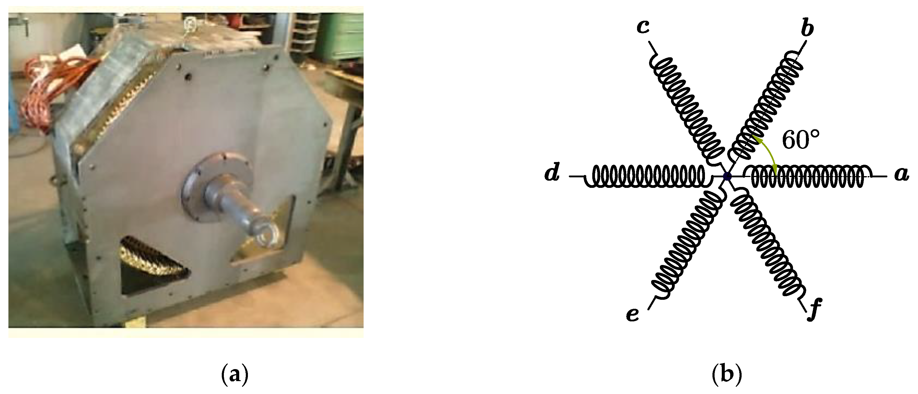
As can be observed in Figure 1, the studied 24 kW induction machine prototype corresponds to a symmetrical six-phase machine (a, b, c, d, e, f) with a single isolated neutral point.
This machine presents a high number of poles (12 pole pairs) to get closer to a real wind speed and to get rid of the gearbox, which usually presents a frequent source of failure in wind turbine systems. The electrical and mechanical parameters of this prototype are given in Appendix A.

2.2. Mathematical Model

In this study, the stator currents of the S6IM (1) are transformed to 2-D orthogonal subspaces by using vector space decomposition T6 with invariant power [29], which is expressed as (2):
[ i α   i β   i x   i y   i 0 +   i 0 ] T = T 6 [ i a   i b   i c   i d   i e   i f ] T
T 6 = 1 3 [ cos ( γ 1 ) cos ( γ 2 ) cos ( γ 3 ) cos ( γ 4 ) cos ( γ 5 ) cos ( γ 6 ) sin ( γ 1 ) sin ( γ 2 ) sin ( γ 3 ) sin ( γ 4 ) sin ( γ 5 ) sin ( γ 6 ) cos ( 2 γ 1 ) cos ( 2 γ 2 ) cos ( 2 γ 3 ) cos ( 2 γ 4 ) cos ( 2 γ 5 ) cos ( 2 γ 6 ) sin ( 2 γ 1 ) sin ( 2 γ 2 ) sin ( 2 γ 3 ) sin ( 2 γ 4 ) sin ( 2 γ 5 ) sin ( 2 γ 6 ) 1 2 1 2 1 2 1 2 1 2 1 2 1 2 1 2 1 2 1 2 1 2 1 2 ]
where [ γ 1 , 2 , 3 , 4 , 5 , 6 ] refers to the phase shift of the stator phase windings.
The subspaces (xy) and (0+0) are relative to the stator copper losses, so that all the electromagnetic conversion is carried out in the (αβ) subspace. Only the fundamental subspace (αβ) will be controlled in this paper because the trade-off involved in producing full torque with minimum losses is a challenging task that requires an optimization solution.
To simplify the control, we move to the synchronous reference frame (dq) (3) using the PARK matrix (4) with the aim of regulating the electromagnetic torque and the rotor flux.
[ i d   i q   ] T = [ P ( θ s ) ] [ i α   i β   ] T
P ( θ s ) = [ cos θ s sin θ s sin θ s cos θ s ]
where θ s is the PARK angle.
The state-space model (5) of the S6IM can now be expressed in the dq reference frame, which is close to that of the three-phase induction machine model:
x ˙ d q = A x d q + B u d q
x d q = [ i s d   i s q   ϕ r d   ϕ r q ] T ;       u d q = [ v s d v s q ] T
A = [ ( R s σ L s + M 2 R r σ L s L r 2 ) ω s R r M σ L s L r 2 M σ L s L r ω r ω s ( R s σ L s + M 2 R r σ L s L r 2 ) M σ L s L r ω r R r M σ L s L r 2 R r M L r 0 R r L r ω s l 0 R r M L r ω s l R r L r ]         ;           B = [ 1 σ L s 0 0 1 σ L s ]
where Rs and Ls are the stator and stator self-inductance, Rr and Lr are the rotor resistance and rotor self-inductance, M is the mutual inductance, p is the number of pole pairs, ωs is the synchronous angular speed, ωsl is the slip angular speed, and ωr is the rotor angular speed.
The leakage coefficient is defined as σ = M 2 / ( L s L r ) and ω r = p Ω , where Ω is the mechanical rotor speed.
The estimated electromagnetic torque of the S6IM is expressed as follows:
T e m = p M L r ( ϕ r d i s q ϕ r q i s d )

2.3. Indirect Rotor Field Oriented Control for S6IM

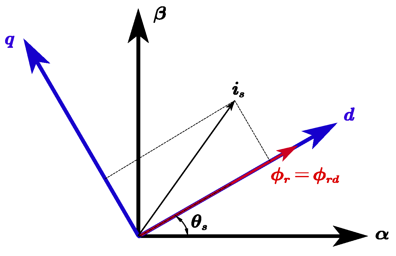
To remove the coupling between the dq stator currents axis present in the electromagnetic torque Equation (8), we will use the IRFOC technique (see Figure 2). The main idea of this strategy is to choose the right PARK position θ s so that the rotor flux position is entirely collinear with the direct axis.
In IRFOC technique, the PARK angle for direct and inverse transformation is determined using:
θ s = ( ω r + ω s l )
When the direct axis is situated collinear with the rotor flux (ϕr = ϕrd), the state model (5) will be simplified for the control, which is described as follows:
{ d i s d d t = ( R s σ L s + M 2 R r σ L s L r 2 ) i s d + 1 σ L s v s d + ω s i s q + R r M σ L s L r 2 ϕ r f e m 1 d i s q d t = ( R s σ L s + M 2 R r σ L s L r 2 ) i s q + 1 σ L s v s q ω s i s d M σ L s L r p Ω ϕ r f e m 2
The rotor flux and slip speed are also computed:
{ ϕ r = M 1 + τ r s i s d ω s l = R r M L r ϕ r i s q
where τ r = L r R r is the rotor time constant.
After the orientation of the rotor flux, the estimated electromagnetic torque will be decoupled and only proportional to the q-axis stator current, in the following manner:
T e m = p M L r ϕ r d i s q

3. Robust Control Strategies for Inner Current Loops of S6IM

3.1. Variable Structure Control

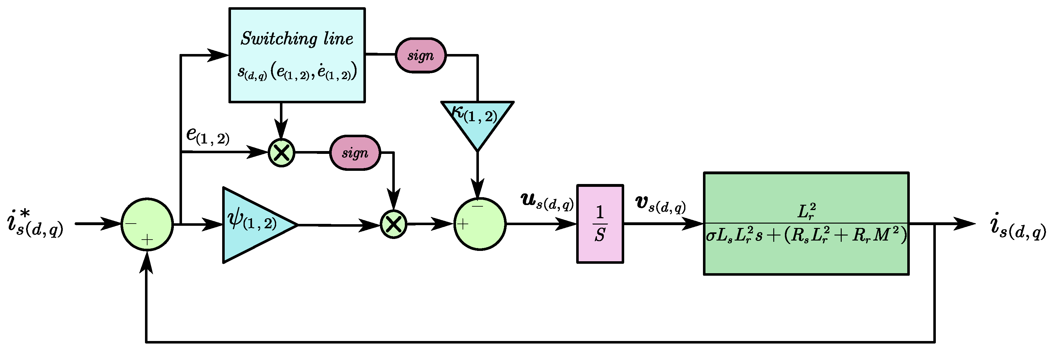
In the literature, SMC is also called variable structure control with different configurations [30]. Nevertheless, they generally present the same evolution in the phase plane, which consists in bringing the state variable trajectory of the system back to a predefined switching line or sliding surface. LFSG will be applied to the inner current loops of the S6IM represented by the dq stator currents.

3.1.1. Design of the SMC with Linear Feedback and Switched Gains for the S6IM

The control law of the SMC with LFSG for the S6IM is described by the following equations for the inner current loops:
{ u s d = v s d = ( ψ 1 e 1 κ 1 s i g n ( s 1 ) ) u s q = v s q = ( ψ 2 e 2 κ 2 s i g n ( s 2 ) )
where
ψ 1 = { k 1                 i f               e 1 s 1 > 0 k 1           i f               e 1 s 1 < 0 ;     ψ 2 = { k 2                 i f               e 2 s 2 > 0 k 2           i f               e 2 s 2 < 0
and ψ1 and ψ2 are the proportional gains of the SMC. According to the evolution of the representative point (RP) in the phase plan, both systems (13) will present two possibilities of feedback, one positive and the other negative (see Figure 3). It should also be noted that the gains (k1; k2; к1; к2) are constants that are defined as positive [18].
The reference tracking errors e1 and e2 for the dq stator currents are firstly defined as follows:
{ e 1 = i s d i s d r e f e 2 = i s q i s q r e f
The integral action in the control law will increase the order of the system to a second order, so the switching lines of each axis will be defined as follows:
{ s 1 e ˙ 1 + λ 1 e 1 = 0 s 2 e ˙ 2 + λ 2 e 2 = 0
where λ1 and λ2 represent the slopes of the switching lines.
Therefore, the new free dynamics of the dq stator currents are described by the switching lines (16), which are developed as the following differential equations:
For the d-axis:
{ e ˙ 1 = x 1 x ˙ 1 = f s d x 1 + b u s d + p 1 ( t )
For the q-axis:
{ e ˙ 2 = x 2 x ˙ 2 = f s q x 2 + b u s q + p 2 ( t )
where, in healthy mode:
f s d = f s q = ( R s σ L s + M 2 R r σ L s L r 2 ) ;         b = 1 σ L s > 0
p1 and p2 are introduced to represent the S6IM disturbances and uncertainties, which are defined by:
{ p 1 ( t ) = f e m 1 + d 1 ( t ) d i s t u r b a n c e s   f o r   d a x i s p 2 ( t ) = f e m 2 + d 2 ( t ) d i s t u r b a n c e s   f o r   q a x i s
d1 and d2 represent the additional unknown disturbances that could affect the state trajectory of d- and q-axis currents.

3.1.2. Stability Proof with Disturbance Rejection

To demonstrate the existence of the sliding phenomenon on the two chosen switching lines (16), the following inequalities [31] have to be proved:
{ lim s 1   0   s ˙ 1 > 0                 a n d               lim s 1 + 0   s ˙ 1 < 0 lim s 2   0   s ˙ 2 > 0                 a n d               lim s 2 + 0   s ˙ 2 < 0
So now, we will determine the expression of the switching lines derivatives, which are expressed as follows:
{ s ˙ 1 = d d t ( e ˙ 1 + λ 1 e 1 ) = f s d e ˙ s d + b u s d + p 1 ( t ) + λ 1 e ˙ s d s ˙ 2 = d d t ( e ˙ 2 + λ 2 e 2 ) = f s q e ˙ s q + b u s q + p 2 ( t ) + λ 2 e ˙ s q
We already know that if the RPs of each current axis (dq) reach the switching lines, we will have e ˙ 1,2 = λ 1,2 e 1,2 . Thus, the final expressions of the switching lines derivatives can be obtained:
{ lim s 1 0 s ˙ 1 = ( f s d e 1 λ 1 2 b ψ 1 ) e s d b u d i s c d + p 1 ( t ) lim s 2 0 s ˙ 2 = ( f s q e 2 λ 2 2 b ψ 2 ) e 2 b u d i s c q + p 2 ( t )
According to the switching law of the SMC–LFSG defined in (13), we obtain:
lim s 1 0 + s ˙ 1 = { ( f s d λ 1 λ 1 2 b k 1 ) e 1 b u d i s c d + p 1 ( t )         i f         e 1 > 0 ( f s d λ 1 λ 1 2 + b k 1 ) e 1 b u d i s c d + p 1 ( t )         i f         e 1 < 0 lim s 1 0 s ˙ 1 = { ( f s d λ 1 λ 1 2 + b k 1 ) e 1 b u d i s c d + p 1 ( t )         i f         e 1 > 0 ( f s d λ 1 λ 1 2 b k 1 ) e 1 b u d i s c d + p 1 ( t )         i f         e 1 < 0 } f o r   d a x i s
lim s 2 0 + s ˙ 2 = { ( f s d λ 2 λ 2 2 b k 2 ) e 2 b u d i s c q + p 2 ( t )         i f         e 2 > 0 ( f s d λ 2 λ 2 2 + b k 2 ) e 2 b u d i s c q + p 2 ( t )         i f         e 2 < 0 lim s 2 0 s ˙ 2 = { ( f s d λ 2 λ 2 2 + b k 2 ) e 2 b u d i s c q + p 2 ( t )         i f         e 2 > 0 ( f s d λ 2 λ 2 2 b k 2 ) e 2 b u d i s c q + p 2 ( t )         i f         e 2 < 0 } f o r   q a x i s
From Equations (23) and (24), the controller parameters can now be chosen to satisfy the condition (20) [32]:
{ k ( 1 ; 2 ) 1 b ( f s d q λ ( 1 ; 2 ) λ ( 1 ; 2 ) 2 )       i f   e ( 1 ; 2 ) > 0 k ( 1 ; 2 ) 1 b ( f s d q λ ( 1 ; 2 ) λ ( 1 ; 2 ) 2 )     i f   e ( 1 ; 2 ) < 0             |   u d i s c d = { 0                                                           i f       s ( 1 ; 2 ) = 0 κ ( 1 ; 2 )   s i g n ( s ( 1 ; 2 ) )           i f       s ( 1 ; 2 ) 0        
Replacing terms (25) in Equations (23) and (24), respectively, we obtain:
{ lim s 1 0 s ˙ 1 = b κ 1 s i g n ( s 1 ) + p 1 ( t ) lim s 2 0 s ˙ 2 = b κ 2 s i g n ( s 2 ) + p 2 ( t )
Multiplying by the switching lines of each axis in both sides of (26), we finally obtain:
{ lim s 1 0 s 1 s ˙ 1 = b κ 1 | s 1 | + s 1 p 1 ( t ) lim s 2 0 s 2 s ˙ 2 = b κ 2 | s 2 | + s 2 p 2 ( t )
To maintain the state trajectory on both sliding surfaces despite the disturbance that can affect the regulation, the following requirement (28) must be satisfied:
{ κ 1 > max t | p 1 ( t ) | κ 2 > max t | p 2 ( t ) |

3.2. Fuzzy Proportional Integral Control Structure

To design a nonlinear controller without any prior knowledge of the model, fuzzy logic control is also a suitable alternative. This approach is based on an expert’s experiences of the process behaviors, which are subsequently combined as inference rules. In most cases, the input variables of the FLC are the error and its variation as shown in Figure 4.

3.2.1. Fuzzification

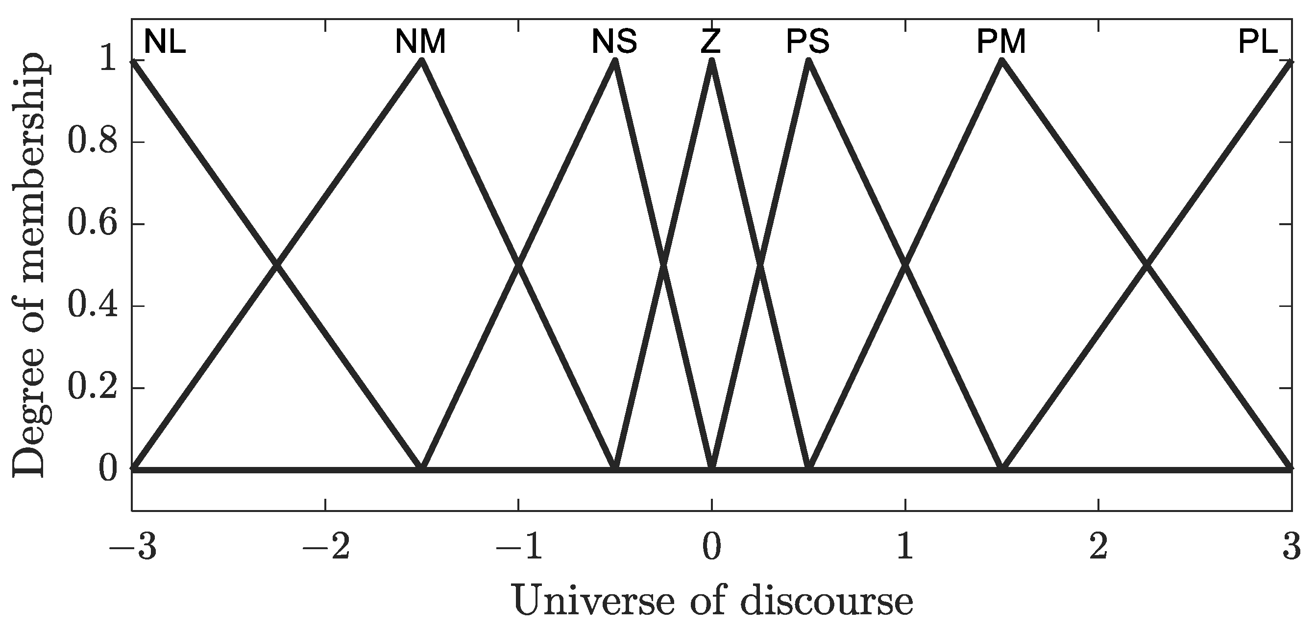
This first step consists in passing from a quantitative quantity to a qualitative one using membership functions for the different input and output variables. For this, seven linguistic sets with a 50% overlap are used, Positive Large (PL), Positive Medium (PM), Positive Small (PS), Zero (Z), Negative Small (NS), Negative Medium (NM), and Negative Large (NL), as shown in Figure 5. We have chosen this well-known configuration with seven symmetrical fuzzy sets because using more than seven linguistic variables increases the computational complexity rather than adding any additional precision [25].
To normalize the input quantities throughout the universe of discourse [−3, 3], the scaling factors k1, k2 are used, reducing the error of the dq currents (ed/eq) and their variations (∆ed/eq). These scaling factors will be determined empirically in such a way that the trajectory of the RP covers the whole universe of discourse. The output scaling factor k3 is determined so that the controller action is weighted to the actuator type.

3.2.2. Inference

The fuzzy controller’s brain is the inference block. In fact, using the fuzzy implication and inference rules specified in Table 1, it may duplicate human decisions and infer fuzzy control actions. The rule base utilized is essentially the same as the one derived using the phase plane technique [33].
For our application, Mamdani’s Max-Min inference technique has been chosen to determine the control decision. In this way, the minimum function realizes the fuzzy implication of the operator (AND), whereas the maximum function realizes the operator (OR).

3.2.3. Defuzzification

In this last stage, the inverse conversion of the fuzzification, i.e., the generation of a numerical value applicable to the process from qualitative quantities obtained by the composition of the rules, is performed. For this, the center of gravity technique is used. This method computes the abscissa of the center of gravity from the associated membership functions in the following way:
Δ v ( s , d ) = i = 1 i = n u i μ ( u i ) i = 1 i = n μ ( u i )
where n is the index of the membership function, ui is the center of the ith fuzzy set, and μ(ui) is the membership degree of ui. This method is well known in the literature for the highly nonlinear nature of the resulting feature.
After the defuzzification of the controller output, the dq control voltages are obtained from the following relationship:
v s ( d , q ) ( k ) = v s ( d , q ) ( k 1 ) + K 3   Δ v s ( d , q )

3.2.4. Real Time Implementation of FPIC Using a Lookup Table

To simplify the control program and therefore reduce the computation time, a fixed decision table using a lookup table (Table 2) is used, as shown in the control loop schema (see Figure 6).
Indeed, Table 2 contains the different values that the output can take for different combinations of input signals ( e d , q ; e d , q ). Additionally, it is crucial to accurately determine the quantity of quantifications in order to prevent the degradation of fuzzy control performance. Indeed, excessively coarse quantification results in a reduction in control precision, while excessively fine quantification requires a substantial memory allocation [34]. Thus, finding the appropriate number of levels becomes imperative to attain a satisfactory compromise. In this way, the number of quantifications in Table 2 is chosen to respect the compromise between precision and memory allocation.

3.3. Fuzzy Sliding Mode Control with Linear Feedback and Switched Gains

The combination of fuzzy logic and sliding mode control offers a powerful approach in control system design [28] by integrating the adaptability and imprecise handling capabilities of fuzzy logic with the robustness and effectiveness of sliding mode control.
Indeed, with its intuitive design, optimization potential, and resemblance to human-like reasoning, the fusion of fuzzy logic and sliding mode control opens up new possibilities for advanced control solutions of complex and dynamic systems. In addition, this combination enlarges the robustness against uncertainties and disturbances while mitigating the undesirable high-frequency ripples associated with chattering, inducing a more stable and efficient control system.
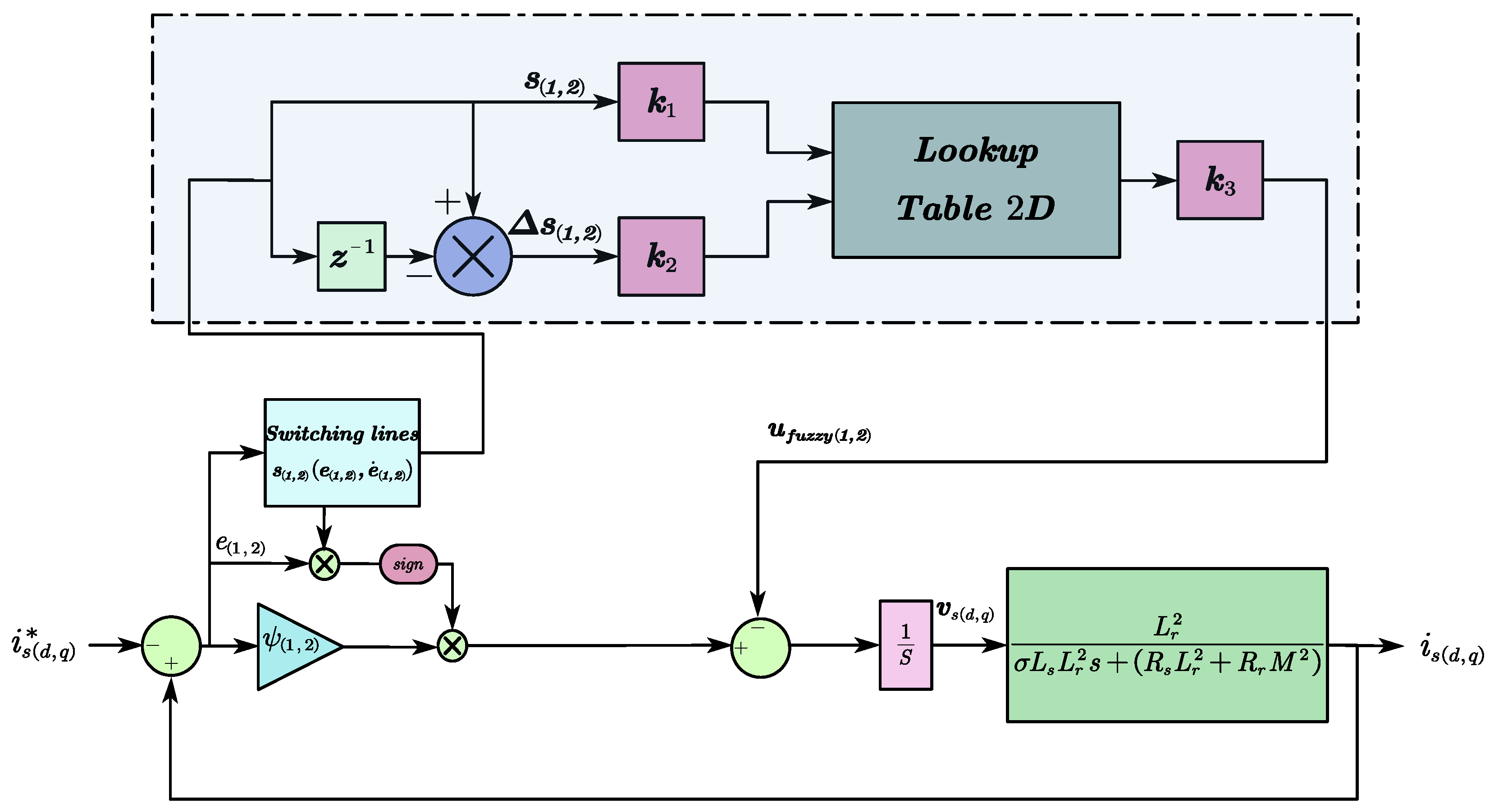
SMC–LFSG itself is prone to the chattering effect due to the nature of its discontinuous control action. However, the fuzzy logic component can add a smoothing or hysteresis effect to the control signal, reducing fast switching between large opposite values and therefore alleviating chattering compared to the signum function. Then, the objective is to substitute the signum function by a fuzzy logic system in the SMC–LFSG law (13).
{ u s d = v s d = ( ψ 1 e 1 u f u z z y 1 ) u s q = v s q = ( ψ 2 e 2 u f u z z y 2 )
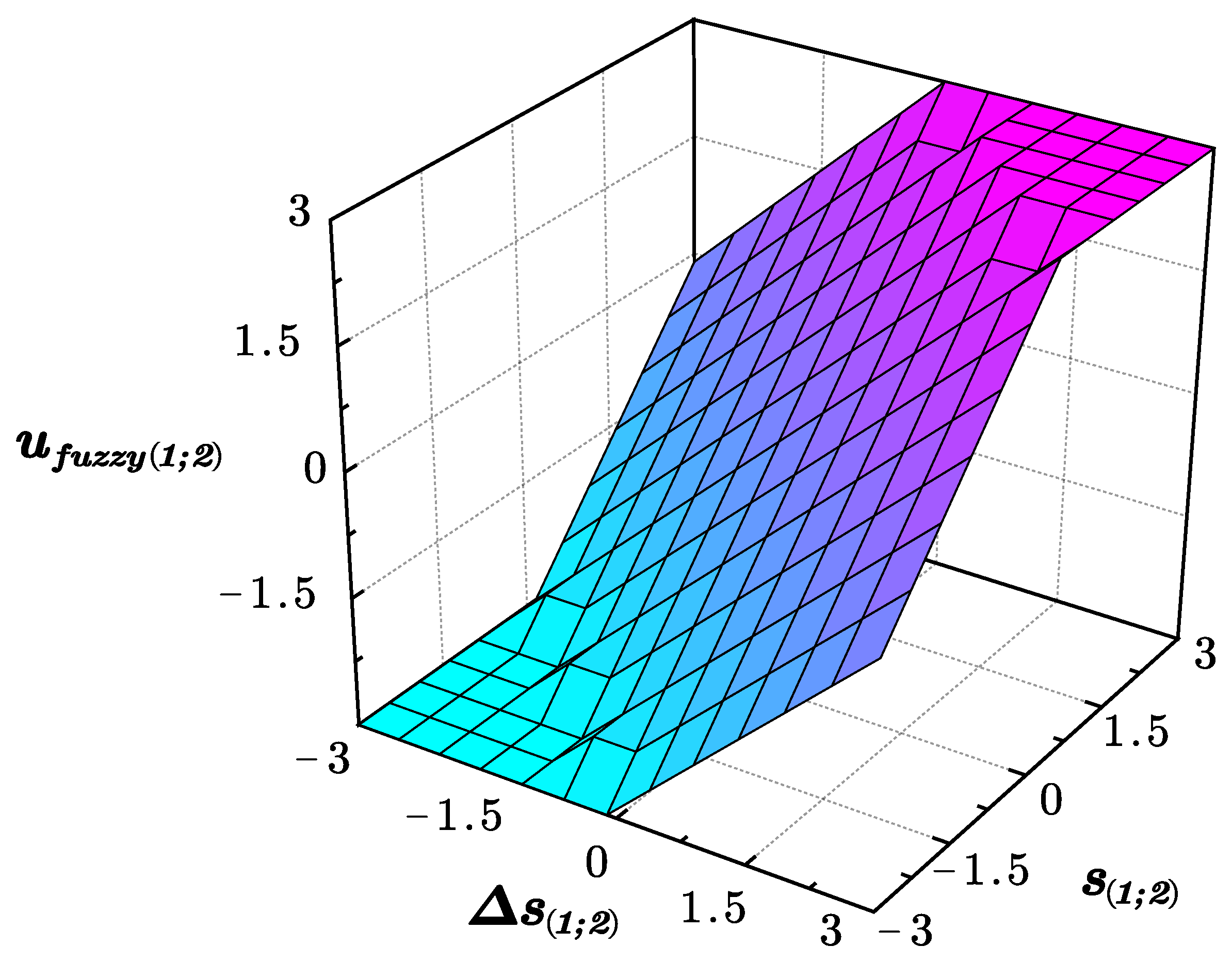
As can be seen in Figure 7, the fuzzy control components for each axis ufuzzy(1;2) will be equivalent to a switching function using the principles of variable structure systems theory [28] and establishing a link between the switching lines and their respective variations, denoted as s(1;2) and s(1;2).
Then, the switching lines and their corresponding variations are used to compute the fuzzy control voltages (see Figure 8), which have been normalized within a universe of discourse ranging from −3 to 3.
The scaling factors are selected to ensure that the trajectory in the phase plane is consistently drawn towards the primary diagonal of the fuzzy matrix (see Table 2), as for the FPIC. This attraction to the diagonal enables the trajectory to smoothly slide along the switching line, as for the SMC–LFSG algorithm [33].

4. Experimental Results in Healthy and Faulty Conditions

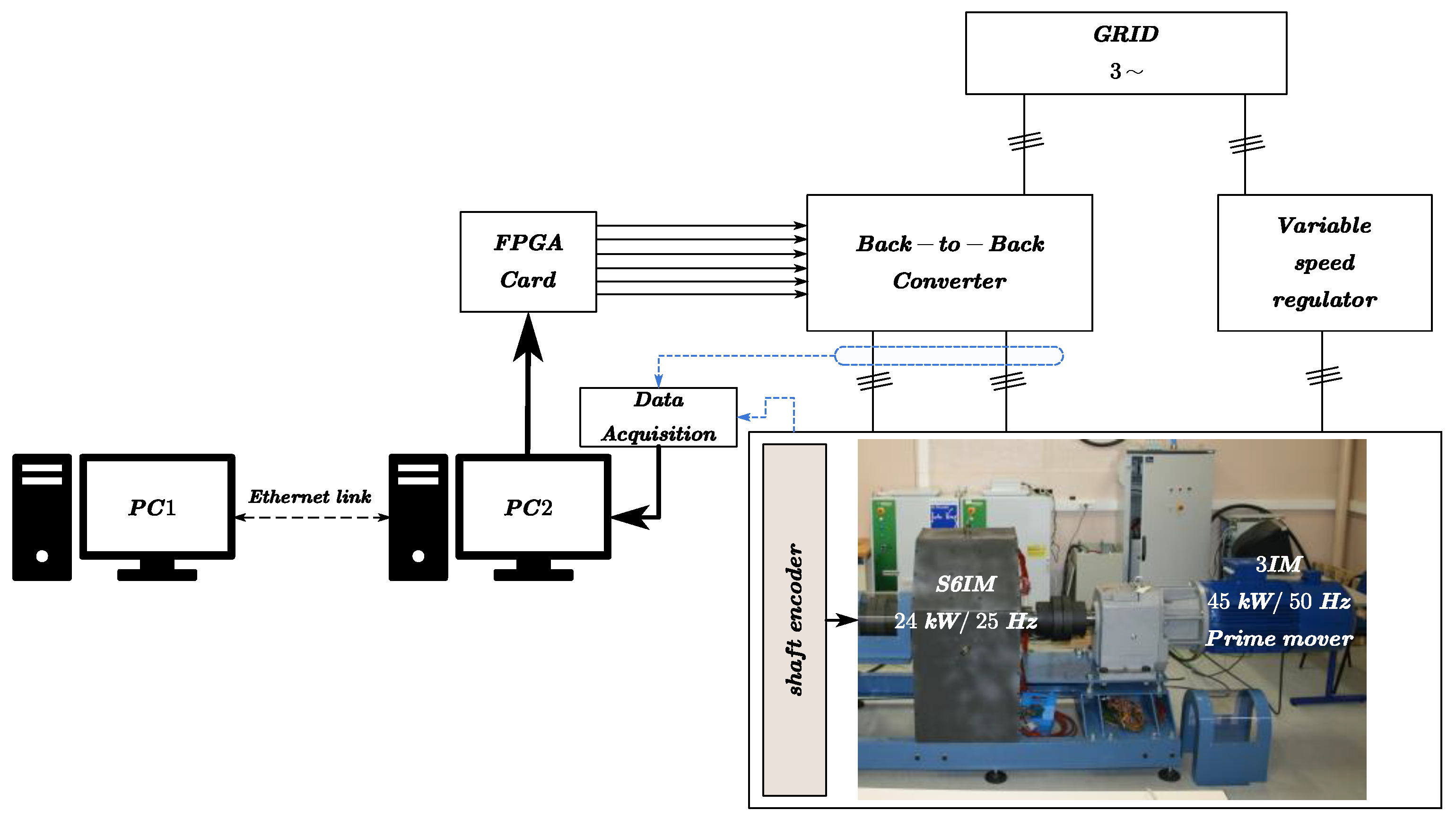
As shown in Figure 9, a geared triphase induction motor (45 kW/1474 rpm) with an output ratio of 1/11 is used to drive the 24 kW S6IM with an industrial variable-speed regulator. In our study, we are interested in the torque control in generator mode. Therefore, the desired electromagnetic torque of the S6IM can be imposed by choosing a negative q-axis stator current reference and the shaft speed is kept constant at 125 rpm.
The generated active power of the S6IM is injected into the grid using back-to-back converters.
The control algorithms are developed using MATLAB/Simulink R2012b software, which are first compiled on the first computer (PC1) and then transferred to the second computer (PC2). The two computers are linked to an ordinary Ethernet network via an IP address. To establish real-time communication between PC1 and PC2, the Secure Shell (SSH) protocol is used, which operates through port TCP/22.
The switching frequency is set to 10 kHz by using the classical Pulse Width Modulation (PWM) generated by a field programmable gate array (FPGA) card. The speed of the shaft is measured by an inductive angle encoder with a resolution of 4096 pulses per revolution.
The parameters of the various controllers (PIC, SMC–LFSG, FSMC–LFSG, and FPIC) are given in Appendix B.
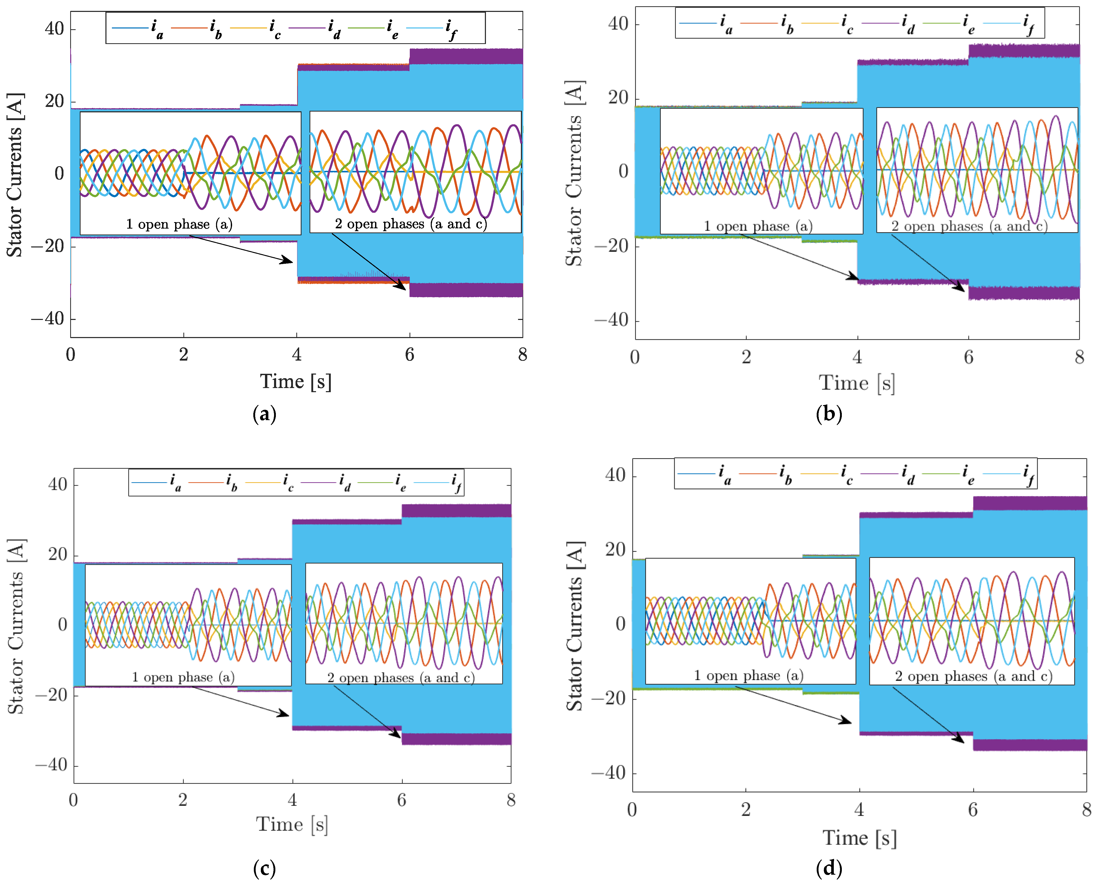
In this section, the capabilities of PIC, SMC-LFSG, FSMC-LFSG, and FPIC applied to the S6IM will be tested experimentally in healthy and faulty conditions. Figure 10 depicts the stator currents of the S6IM controlled by these four different control algorithms.
To ensure that the currents provided by the converters on the machine side do not exceed their maximum values after the loss of one or two phases, the isq current reference has been limited to −10 A at time t = 3 s. As can be seen, the loss of phase “a” has been introduced at time t = 4 s and then phases “a” and “c” at time t = 6 s. We can observe the stator currents’ behaviors on the zooms with each controller under HMO and FMO.
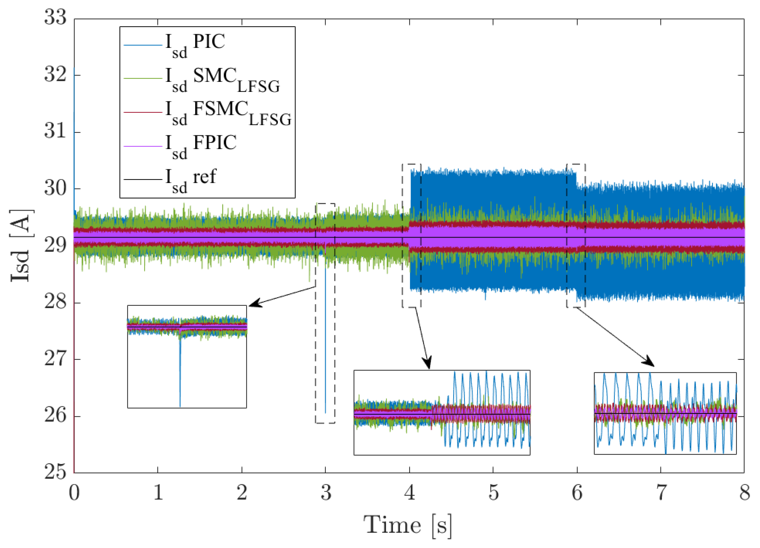
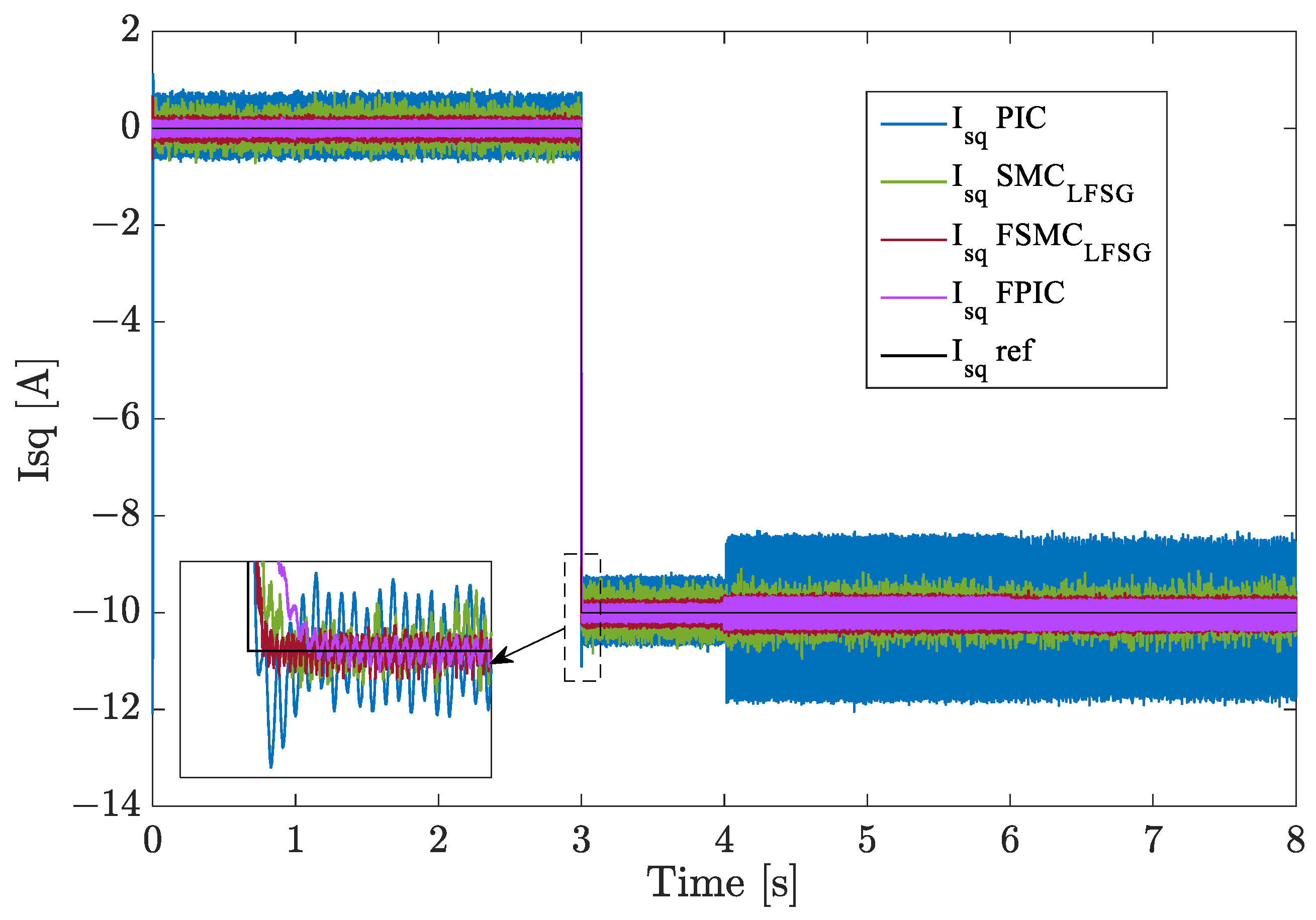
Figure 11 and Figure 12 depict the experimental evolution of the stator currents along the d and q axes, respectively, with the same four controllers (PIC, SMC-LFSG, FPIC, and FSMC–LFSG) tested under the same test conditions. At time 3 s, we can see that the classical controller (PIC) is very sensitive to reference variation, as can be clearly seen during the reference for both dq currents. Moreover, it exhibits significant ripples following the loss of one phase at time 4 s. Otherwise, the use of SMCLFSG results in fewer oscillations compared to the PIC in both d and q stator currents. In the same way, the FPIC and the FSMCLFSG demonstrate consistent performance in both conditions (HMO and FMO). Nevertheless, by comparing all controller results, FPIC presents the best adaptability, with reduced ripples in the dq stator currents and improved accuracy.

5. Comparison of the Controllers under Healthy and Faulty Modes

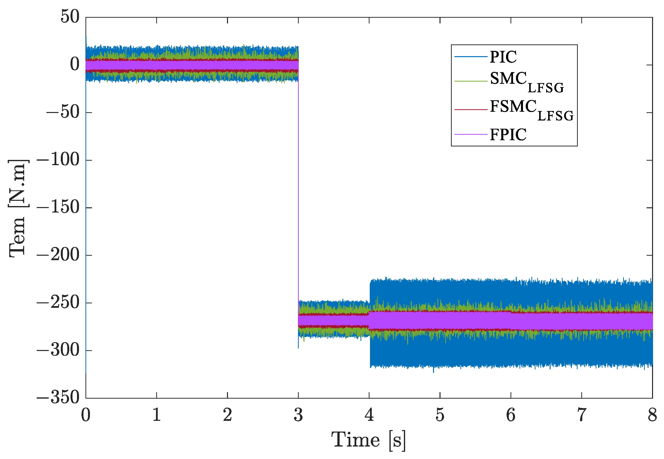
In this section, the estimated electromagnetic torque (see Figure 13) of the S6IM using the four controllers (PIC, SMCLFSG, FSMCLFSG, and FPIC) is depicted in the same conditions as those in Section 4. When the phases (“a” and “c”) are lost (after t = 4 s), it is obvious that the PIC is no longer at all suitable. Additionally, the SMC–LFSG proves to be robust by allowing the compensation of parameter variations and uncertainties related to this type of electrical fault. We also notice that this technique of SMC based on LFSG presents less overshoot compared to the other sliding mode algorithms implemented in [16,35]. With FSMC–LFSG, the torque ripples minimization is improved compared to the SMC–LFSG by integrating the fuzzy logic component, providing better performances in terms of rising time and overshoot (see Table 3). The electromagnetic torque ripples are also reduced compared to the SMC–LFSG, with better tracking of desired trajectories. However, despite the long rise time of the FPIC, it generates the least amount of electromagnetic torque ripples and exhibits improved tolerance after OPCs (“a” and “c”), which justifies its high robustness compared to the other controllers.
Table 4 introduces a synthesis of the mean squared error (MSE) for the dq stator currents in HMO and FMO. We can clearly deduce that the FPIC allows a better reduction of the MSE compared to other controllers (PIC, SMC–LFSG, and FSMC–LFSG) in both operational conditions HMO and FMO.
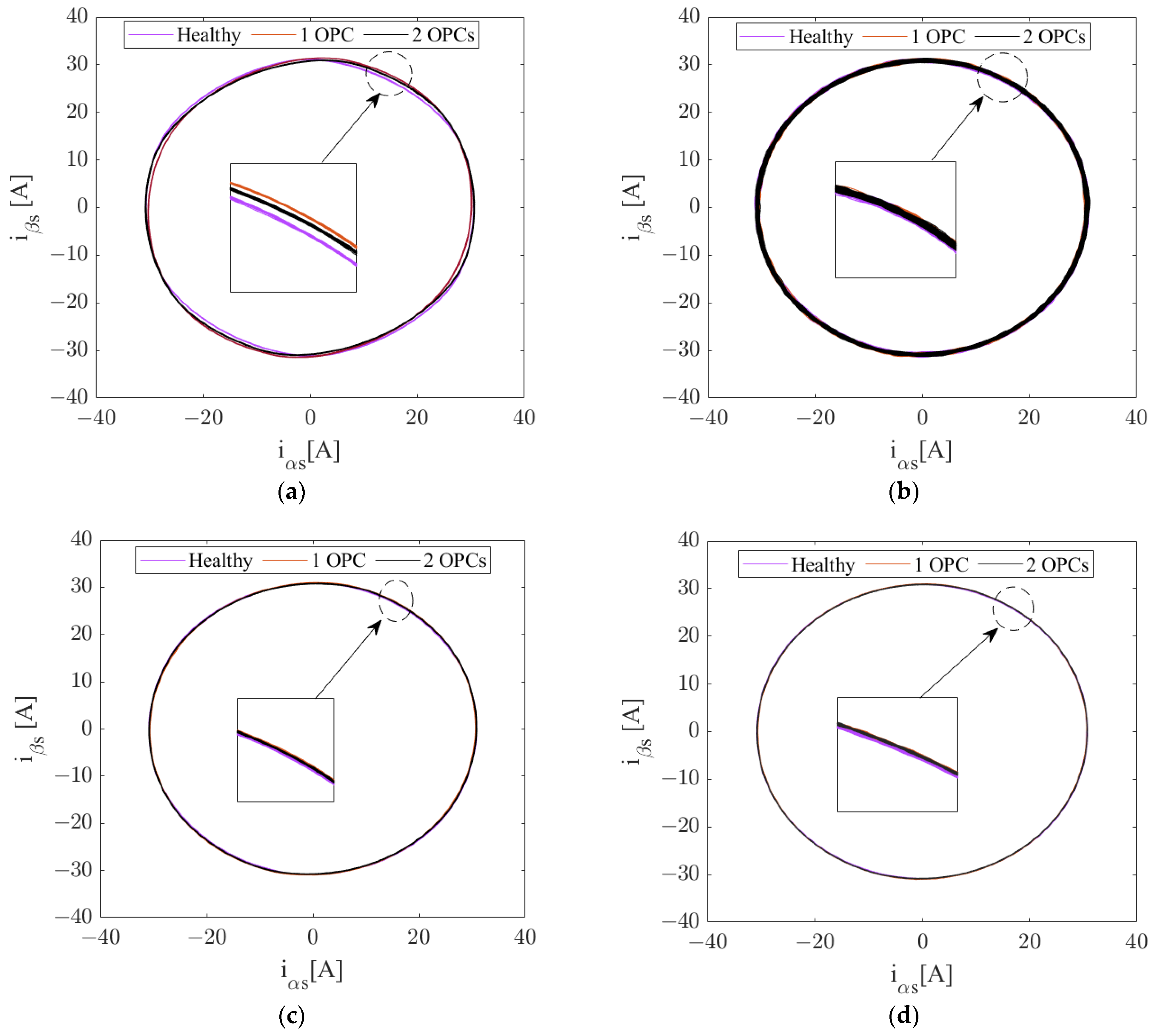
Always in the same conditions, Figure 14 depicts the αβ stator currents with the four proposed controllers in HMO and FMO. For the PIC (see Figure 14a), we can see in the zoom that the trajectories of the αβ stator currents are disturbed after the opening of the phases, which explains the large oscillations in the extracted electromagnetic torque of the S6IM. On the other hand, the other algorithms, SMCLFSG, FPIC and FSMCLSFG, maintain the same circular pattern in HMO and FMO.

6. Conclusions

In this paper, the proposed robust algorithms (SMC–LFSG, FPIC, and FSMC–LFSG) for the inner current loops of the S6IM have been experimentally tested and compared under HMO and FMO of the S6IM in our laboratory.
The stability of the SMC–LFSG has been proved for the S6IM to ensure convergence of the control law. The experimental results with SMC–LFSG show good performance in terms of robustness and accuracy in HMO and FMO for the regulation of inner currents and electromagnetic torque. The only drawback of this control strategy is that the gain of the discontinuous part has to be chosen so that it is large enough to eliminate the upper limit of the model’s uncertainties and parameter variations, which can lead to the undesirable phenomenon of chattering.
This effect can be reduced by introducing fuzzy logic in the determination of the discontinuous part. Indeed, with this association, called FSMC–LFSG, the control signal can be smoothed, alleviating the chattering effect in HMO and FMO.
Finally, with FPIC, the extracted electromagnetic torque presents a higher quality since the ripples are advantageously minimized. Indeed, this control strategy demonstrates a very efficient robustness in comparison with the other controllers. Combining this algorithm with S6IM makes the energy conversion process even more robust to the disturbances and parameter variations.
The next challenge of this study is to increase the machine’s efficiency by minimizing losses and finding the optimum point of operation in faulty mode operation for different possible open-phase scenarios.
Author Contributions

Conceptualization, O.B., F.B. and A.Y.; methodology, O.B., F.B. and A.Y.; software, O.B., F.B. and A.Y.; validation, O.B., F.B. and A.Y.; formal analysis, O.B., F.B. and A.Y.; investigation, O.B., F.B. and A.Y.; resources, O.B., F.B. and A.Y.; data curation, O.B., F.B. and A.Y.; writing—original draft preparation, O.B., F.B. and A.Y.; writing—review and editing, O.B., F.B. and A.Y.; visualization, O.B., F.B. and A.Y.; supervision, F.B. and A.Y.; project administration, F.B. and A.Y.; funding acquisition, F.B. and A.Y. All authors have read and agreed to the published version of the manuscript.

Funding

This research was funded by the «Hauts de France» Region Council, the European Regional Development Fund (ERDF), and Grand-Soissons Agglomeration.

Data Availability Statement

Not applicable.

Acknowledgments

The authors gratefully acknowledge the «Hauts de France» Region Council, the European Regional Development Fund (ERDF), and Grand-Soissons Agglomeration for the financial support provided.

Conflicts of Interest

The authors declare no conflict of interest.

Abbreviations

The following abbreviations are used in this manuscript:
OPCOpen phase circuit
IRFOCIndirect rotor field-oriented control
HMOHealthy mode operation
FMOFaulty mode operation
MPCModel predictive control
SMCSliding mode control
LFSGLinear feedback and switched gains
FLCFuzzy logic control
FSMCFuzzy sliding mode control
FPICFuzzy proportional integral
RPRepresentative point
MSEMean squared error

Appendix A

Table A1. Rated parameters of the S6IM.
ParameterValueUnit
Rated Power24kW
Rated Torque2350Nm
Rated Voltage230V
Rated Speed119rpm
Rated Current 32.2A
Frequency25Hz
Number of pole pairs12-
Stator Resistance Rs0.262
Rotor Resistance Rr0.64
Stator Inductance Ls0.0827H
Rotor Inductance Lr0.0813H
Mutual Inductance M0.0789H
Friction Coefficient21.39Nm/rad/s
Inertia Coefficient704Kg·m2

Appendix B

Table A2. PIC parameters.
ParametersValues
Proportional gains Ki(dq)1383
Integral gains Kp(dq)5.5
Table A3. SMC–LFSG parameters.
ParametersValues
Proportional gains k1; k25000
Discontinuous term gains K1; K220,000
Slope of the sliding surfaces λ1; λ2200
Table A4. FSMC–LFSG parameters.
ParametersValues
Proportional gains k1; k25000
Slope of the sliding surfaces λ1; λ2200
Input scaling factors k11/1000
Input scaling factors k21/10,000,000
Output scaling factors k340,000
Table A5. FPIC parameters.
ParametersValues
Input scaling factors k10.02
Input scaling factors k20.00001
Output scaling factors k370

References

  1. Rezazadeh, G.; Tahami, F.; Capolino, G.-A.; Nasiri-Gheidari, Z.; Henao, H.; Sahebazamani, M. Improved Design of a Six-Phase Squirrel Cage Induction Motor With Pseudo-Concentrated Windings. IEEE J. Emerg. Sel. Top. Ind. Electron. 2021, 3, 1187–1194. [Google Scholar] [CrossRef]
  2. Metwly, M.Y.; Abdel-Khalik, A.S.; Hamad, M.S.; Ahmed, S.; Elmalhy, N.A. Multiphase Stator Winding: New Perspectives, Advanced Topologies, and Futuristic Applications. IEEE Access 2022, 10, 103241–103263. [Google Scholar] [CrossRef]
  3. Barrero, F.; Duran, M.J. Recent advances in the design, modeling, and control of multiphase machines—Part I. IEEE Trans. Ind. Electron. 2015, 63, 449–458. [Google Scholar] [CrossRef]
  4. Duran, M.J.; Barrero, F. Recent advances in the design, modeling, and control of multiphase machines—Part II. IEEE Trans. Ind. Electron. 2015, 63, 459–468. [Google Scholar] [CrossRef]
  5. Yepes, A.G.; Lopez, O.; Gonzalez-Prieto, I.; Duran, M.J.; Doval-Gandoy, J. A comprehensive survey on fault tolerance in multiphase ac drives, Part 1: General overview considering multiple fault types. Machines 2022, 10, 208. [Google Scholar] [CrossRef]
  6. Yepes, A.G.; Gonzalez-Prieto, I.; Lopez, O.; Duran, M.J.; Doval-Gandoy, J. A comprehensive survey on fault tolerance in multiphase ac drives, Part 2: Phase and switch open-circuit faults. Machines 2022, 10, 221. [Google Scholar] [CrossRef]
  7. Levi, E. Multiphase Electric Machines for Variable-Speed Applications. IEEE Trans. Ind. Electron. 2008, 55, 1893–1909. [Google Scholar] [CrossRef]
  8. Che, H.S.; Duran, M.J.; Levi, E.; Jones, M.; Hew, W.-P.; Rahim, N.A. Postfault Operation of an Asymmetrical Six-Phase Induction Machine With Single and Two Isolated Neutral Points. IEEE Trans. Power Electron. 2014, 29, 5406–5416. [Google Scholar] [CrossRef]
  9. Baneira, F.; Doval-Gandoy, J.; Yepes, A.G.; Lopez, O.; Perez-Estevez, D. Control Strategy for Multiphase Drives with Minimum Losses in the Full Torque Operation Range Under Single Open-Phase Fault. IEEE Trans. Power Electron. 2016, 32, 6275–6285. [Google Scholar] [CrossRef]
  10. Pantea, A.; Yazidi, A.; Betin, F.; Carriere, S.; Sivert, A.; Vacossin, B.; Henao, H.; Capolino, G.-A. Fault-Tolerant Control of a Low-Speed Six-Phase Induction Generator for Wind Turbines. IEEE Trans. Ind. Appl. 2019, 55, 426–436. [Google Scholar] [CrossRef]
  11. Gonzalez-Prieto, I.; Duran, M.J.; Aciego, J.J.; Martin, C.; Barrero, F. Model Predictive Control of Six-Phase Induction Motor Drives Using Virtual Voltage Vectors. IEEE Trans. Ind. Electron. 2017, 65, 27–37. [Google Scholar] [CrossRef]
  12. Ayala, M.; Doval-Gandoy, J.; Rodas, J.; Gonzalez, O.; Gregor, R.; Rivera, M. A Novel Modulated Model Predictive Control Applied to Six-Phase Induction Motor Drives. IEEE Trans. Ind. Electron. 2020, 68, 3672–3682. [Google Scholar] [CrossRef]
  13. Gonzalez, O.; Ayala, M.; Romero, C.; Delorme, L.; Rodas, J.; Gregor, R.; Gonzalez-Prieto, I.; Duran, M.J. Model Predictive Current Control of Six-Phase Induction Motor Drives Using Virtual Vectors and Space Vector Modulation. IEEE Trans. Power Electron. 2022, 37, 7617–7628. [Google Scholar] [CrossRef]
  14. Gonzalez-Prieto, A.; Gonzalez-Prieto, I.; Duran, M.J.; Barrero, F. Efficient Model Predictive Control with Natural Fault-Tolerance in Asymmetrical Six-Phase Induction Machines. Energies 2019, 12, 3989. [Google Scholar] [CrossRef]
  15. Kali, Y.; Saad, M.; Doval-Gandoy, J.; Rodas, J. Discrete Terminal Super-Twisting Current Control of a Six-Phase Induction Motor. Energies 2021, 14, 1339. [Google Scholar] [CrossRef]
  16. Kali, Y.; Rodas, J.; Doval-Gandoy, J.; Ayala, M.; Gonzalez, O. Enhanced Reaching-Law-Based Discrete-Time Terminal Sliding Mode Current Control of a Six-Phase Induction Motor. Machines 2023, 11, 107. [Google Scholar] [CrossRef]
  17. Bouyahia, O.; Betin, F.; Yazidi, A. Fault Tolerant Variable Structure Control Of Six-phase Induction Generator For Wind Turbines. IEEE Trans. Energy Convers. 2022, 37, 1579–1588. [Google Scholar] [CrossRef]
  18. Bouyahia, O.; Betin, F.; Yazidi, A. Optimal Sliding Mode Control of a Symmetrical Six-Phase Induction Generator for Wind Turbines. IEEE Trans. Ind. Appl. 2022, 58, 7308–7317. [Google Scholar] [CrossRef]
  19. El-Sousy, F.F.M.; Amin, M.M.; Mohammed, O.A. Robust Adaptive Neural Network Tracking Control With Optimized Super-Twisting Sliding-Mode Technique for Induction Motor Drive System. IEEE Trans. Ind. Appl. 2022, 58, 4134–4157. [Google Scholar] [CrossRef]
  20. Abderazak, S.; Farid, N. Comparative study between Sliding mode controller and Fuzzy Sliding mode controller in a speed control for doubly fed induction motor. In Proceedings of the 2016 4th International Conference on Control Engineering & Information Technology (CEIT), Hammamet, Tunisia, 16–18 December 2016. [Google Scholar] [CrossRef]
  21. Gabbi, T.S.; de Araujo, M.B.; Rocha, L.R.; Scalcon, F.P.; Gründling, H.A.; Vieira, R.P. Discrete-time sliding mode controller based on backstepping disturbance compensation for robust current control of PMSM drives. ISA Trans. 2022, 128, 581–592. [Google Scholar] [CrossRef]
  22. Fnaiech, M.A.; Betin, F.; Capolino, G.-A.; Fnaiech, F. Fuzzy Logic and Sliding-Mode Controls Applied to Six-Phase Induction Machine With Open Phases. IEEE Trans. Ind. Electron. 2009, 57, 354–364. [Google Scholar] [CrossRef]
  23. Elbarbary, Z.; Azeem, M.F.; Azazi, H.Z. Adaptive Fuzzy-Based IRFOC of Speed Sensorless Six-Phase Induction Motor Drive System. J. Circuits, Syst. Comput. 2020, 29, 2050062. [Google Scholar] [CrossRef]
  24. Raja, D.; Ravi, G. Dynamic modeling and control of five phase SVPWM inverter fed induction motor drive with intelligent speed controller. J. Ambient. Intell. Humaniz. Comput. 2020, 1–11. [Google Scholar] [CrossRef]
  25. Betin, F.; Pinchon, D.; Capolino, G.-A. Fuzzy logic applied to speed control of a stepping motor drive. IEEE Trans. Ind. Electron. 2000, 47, 610–622. [Google Scholar] [CrossRef]
  26. Bouyahia, O.; Betin, F.; Yazidi, A. Fault-Tolerant Fuzzy Logic Control of a 6-Phase Axial Flux Permanent-Magnet Synchronous Generator. Energies 2022, 15, 1301. [Google Scholar] [CrossRef]
  27. Barrero, F.; Gonzalez, A.; Torralba, A.; Galvan, E.; Franquelo, L. Speed control of induction motors using a novel fuzzy sliding-mode structure. IEEE Trans. Fuzzy Syst. 2002, 10, 375–383. [Google Scholar] [CrossRef]
  28. Li, H.; Gatland, H.; Green, A. Fuzzy variable structure control. IEEE Trans. Syst. Man Cybern. Part B 1997, 27, 306–312. [Google Scholar] [CrossRef]
  29. Levi, E.; Bojoi, R.; Profumo, F.; Toliyat, H.A.; Williamson, S. Multiphase induction motor drives: A technology status review. Iet Electr. Power Appl. 2007, 1, 489–516. [Google Scholar] [CrossRef]
  30. Mousavi, Y.; Bevan, G.; Kucukdemiral, I.B.; Fekih, A. Sliding mode control of wind energy conversion systems: Trends and applications. Renew. Sustain. Energy Rev. 2022, 167, 112734. [Google Scholar] [CrossRef]
  31. Itkis, U. Control Systems of Variable Structure; Wiley: Hoboken, NJ, USA, 1976. [Google Scholar]
  32. Emelyanov, S.V. Variable Structure Control Systems; Nauka: Moscow, Russia, 1967. [Google Scholar]
  33. Li, H.-X.; Gatland, H. A new methodology for designing a fuzzy logic controller. IEEE Trans. Syst. Man Cybern. 1995, 25, 505–512. [Google Scholar] [CrossRef]
  34. Rutherford, D.; Bloore, G. The implementation of fuzzy algorithms for control. Proc. IEEE 1976, 64, 572–573. [Google Scholar] [CrossRef]
  35. Kali, Y.; Ayala, M.; Rodas, J.; Saad, M.; Doval-Gandoy, J.; Gregor, R.; Benjelloun, K. Current Control of a Six-Phase Induction Machine Drive Based on Discrete-Time Sliding Mode with Time Delay Estimation. Energies 2019, 12, 170. [Google Scholar] [CrossRef]
Figure 1. Symmetrical six-phase induction generator: (a) S6IM Prototype; (b) Stator windings configuration.
Energies 16 06702 g001
Figure 2. IRFOC strategy.
Energies 16 06702 g002
Figure 3. Control scheme of SMC–LFSG law applied to inner current loops of the S6IM.
Energies 16 06702 g003
Figure 4. Basic structure of FPIC.
Energies 16 06702 g004
Figure 5. Fuzzy sets for input and output variables.
Energies 16 06702 g005
Figure 6. FPIC implementation using lookup table.
Energies 16 06702 g006
Figure 7. Switching function based on fuzzy logic.
Energies 16 06702 g007
Figure 8. FSMC–LFSG control scheme.
Energies 16 06702 g008
Figure 9. Test bed configuration.
Energies 16 06702 g009
Figure 10. Stator currents in HMO and FMO: (a) with PIC (b) with SMC–LFSG (c) with FSMC–LFSG; (d) with FPIC.
Energies 16 06702 g010
Figure 11. Direct-axis stator currents for the four controllers at Ω = 125 rpm.
Energies 16 06702 g011
Figure 12. Quadrature-axis stator currents for the four controllers at Ω = 125 rpm.
Energies 16 06702 g012
Figure 13. Estimated electromagnetic torque in dq reference frame of S6IM.
Energies 16 06702 g013
Figure 14. αβ stator currents in HMO and FMO: (a) with PI controller; (b) with SMC–LFSG; (c) with FSMC–LFSG; (d) with FPIC.
Energies 16 06702 g014
Table 1. The Inference Matrix.
e\∆eNLNMNSZPSPMPL
PLZPSPMPLPLPLPL
PMNSZPSPMPLPLPL
PSNMNSZPSPMPLPL
ZNLNMNSZPSPMPL
NSNLNLNMNSZPSPM
NMNLNLNLNMNSZPS
NLNLNLNLNLNMNSZ
Table 2. Lookup table.
∆e\e−3−2.5−2−1.5−1−0.500.511.522.53
−3−3−3−3−3−3−3−3−2.5−2−1.5−1−0.50
−2.5−3−3−3−3−3−2.5−2.5−2−1.5−1−0.500.5
−2−3−3−3−3−3−2.5−2−1.5−1−0.500.51
−1.5−3−3−3−2.5−2.5−2−1.5−1−0.500.511.5
−1−3−3−3−2.5−2−1.5−1−0.500.511.52
−0.5−3−2.5−2.5−2−1.5−1−0.500.511.522.5
0−3−2.5−2−1.5−1−0.500.511.522.53
0.5−2.5−2−1.5−1−0.500.511.522.52.53
1−2−1.5−1−0.500.511.522.5333
1.5−1.5−1−0.500.511.522.52.5333
2−1−0.500.511.522.533333
2.5−0.500.511.522.52.533333
300.511.522.53333333
Table 3. Performance analysis between controllers in HMO.
Mode OperationHealthy
PerformanceRise Time (ms)Overshoot (%)
PIC3.110.7
SMC–LFSG101.1
FSMC–LFSG100.5
FPIC19.60.7
Table 4. Numerical comparison between controllers with a sampling frequency of 10 kHz.
Mode OperationHealthy1 OPC2 OPCs
Time (s)(3–4)(4–6)(6–8)
ApproachMSE(d)MSE(q)MSE(d)MSE(q)MSE(d)MSE(q)
PIC0.04450.14470.52390.90280.28670.8157
SMC–LFSG0.02370.03520.03090.05540.02860.0560
FSMC–LFSG0.00450.00960.01580.01710.01610.0236
FPIC0.00130.00600.00810.02340.00460.0216
Disclaimer/Publisher’s Note: The statements, opinions and data contained in all publications are solely those of the individual author(s) and contributor(s) and not of MDPI and/or the editor(s). MDPI and/or the editor(s) disclaim responsibility for any injury to people or property resulting from any ideas, methods, instructions or products referred to in the content.