Identification of Free Components during Non-Simultaneous Complex Faults in Overhead Lines: A Review


Abstract
:1. Introduction
Historical Review of Research
- ATP-EMTP [16], popular especially among individual scientists.
- EMTP® [17], a very advanced simulation tool with load-flow initialization; here, a very accurate frequency-dependent wide-band line (or cable) model is available.
- MicroTran [18], mainly (but not only) for students of the University of British Columbia, very user-friendly. Applied in over 25 countries.
2. Optimal Model of High-Voltage Transmission Lines in Fault States
2.1. Principles and Conditions
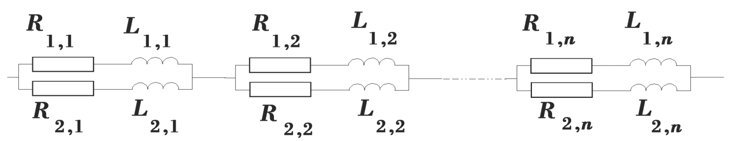
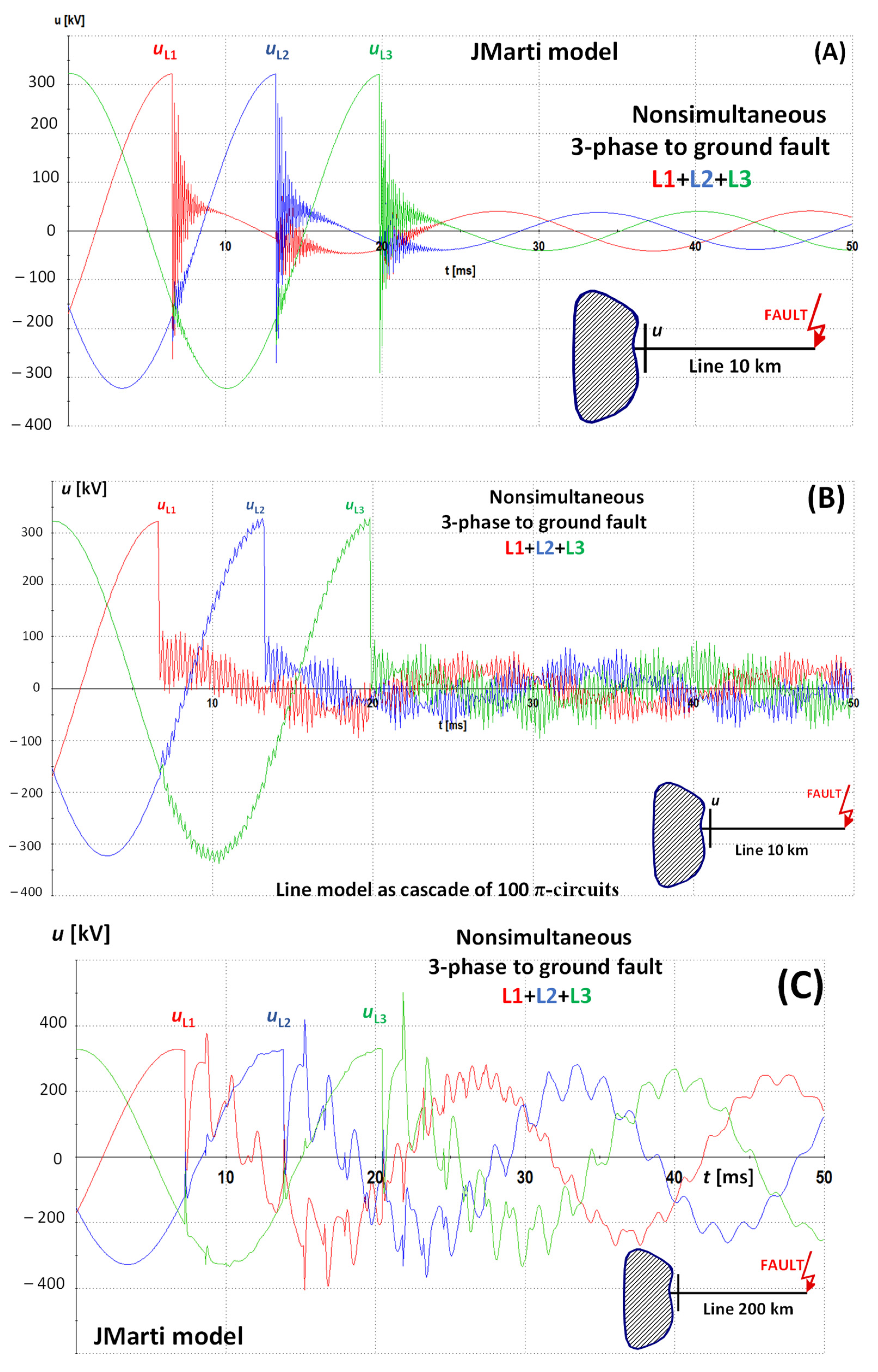
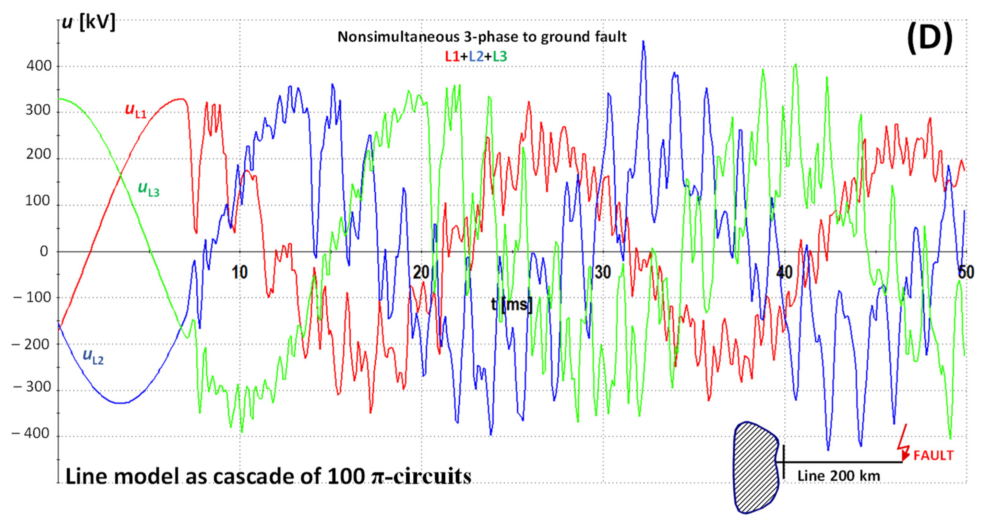
- Lumped-parameter (π-equivalent) circuit model [18], which is accurate only at the frequency at which the parameters are evaluated. One π-circuit can serve as a representation of only one natural resonant frequency of the considered circuit (in most cases: the power system frequency, i.e., 50 or 60 Hz). When consisting of k-sections of π-circuits, k natural frequencies can be represented, although the amplitude is accurate only for the first one. The whole line is divided into n sections, where the parameters of each have a ratio of 1/n in reference to the line constants of the whole line. For steady-state calculations, this representation is reasonably accurate if each π-circuit is not too long. The equivalent transmission line model of the cascaded π-shape required corrections for long transmission lines (approximately 200 to 250 km in length).
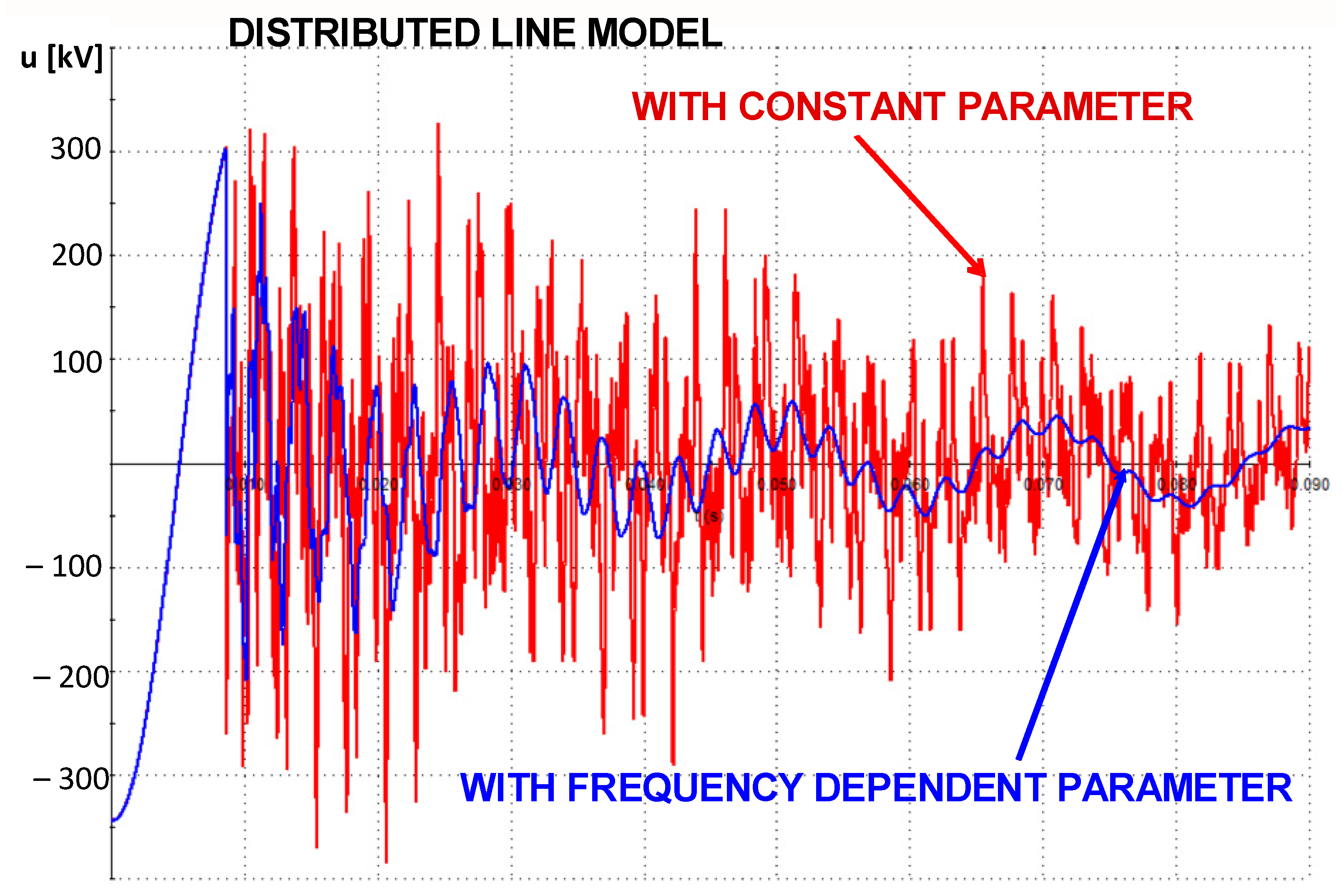
- Lossless distributed line model [18] can represent traveling-wave behavior but is valid only for the frequency at which the parameters are computed. Several natural resonant frequencies are represented approximately for an open-circuited line. The accuracy of this model decreases when considering matching and short-circuited lines in a high-frequency region.
- JMarti model [19] (FD)—in the modal domain—is used in many applications in EMT-like programs (however, in this paper, the frequency-dependent transformation matrix was neglected). Despite this imperfection and any critical remarks, there is a sufficiently good match between the FD model and other models (and a good agreement with measurements).
- Frequency-dependent line model in the phase domain. To avoid the numerical instability by the use of FD [20], a phase-domain line model was established [21,22]. This approach has become the most accurate frequency-dependent wide-band line model in EMTP®. A drawback is that software coding and advanced numerical computations are required.
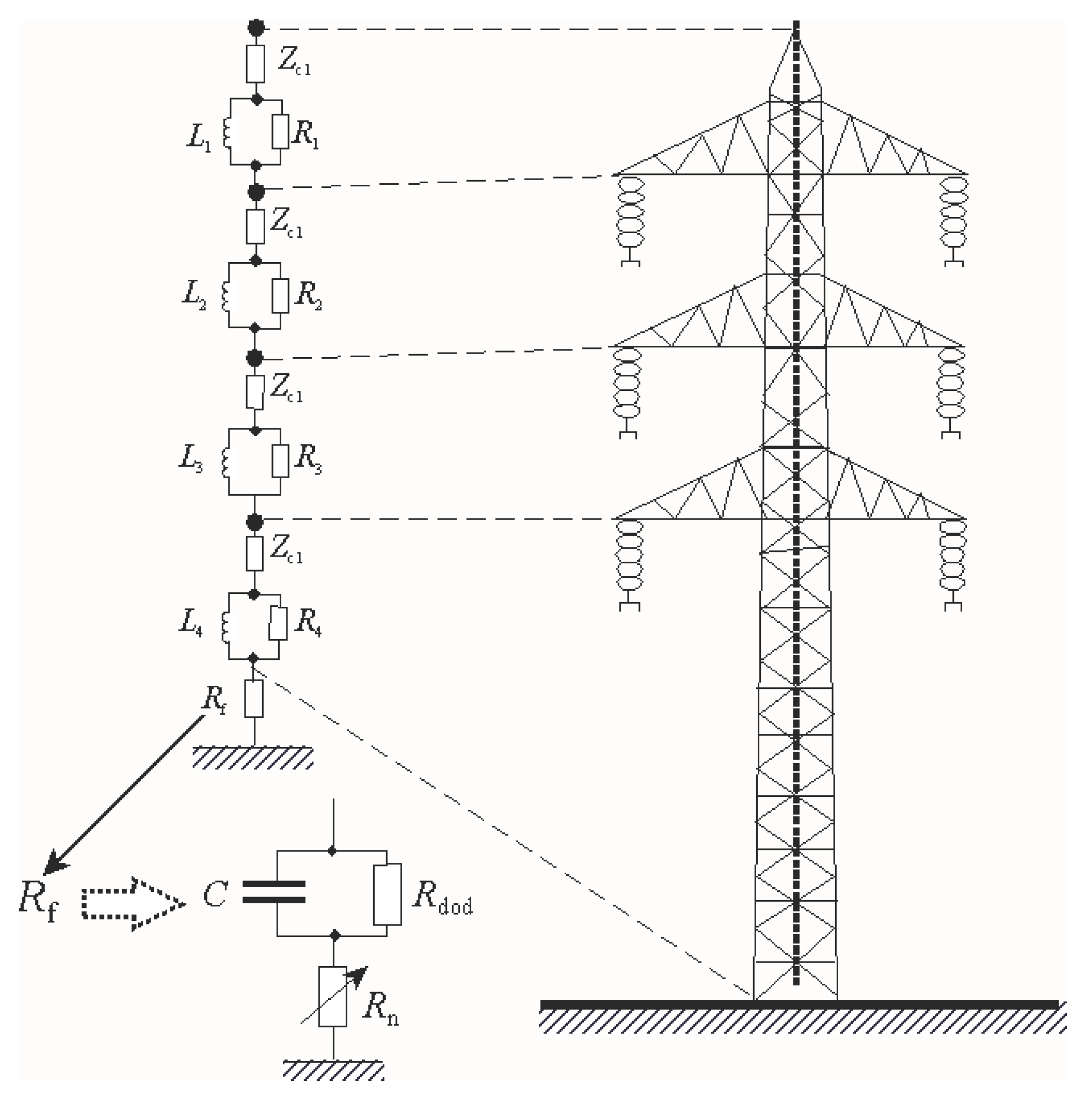
2.2. Line Modeling including the Influence of Higher Frequencies
3. Importance of Free Components during Faults
4. Short-Circuit Currents during Non-Simultaneous Faults
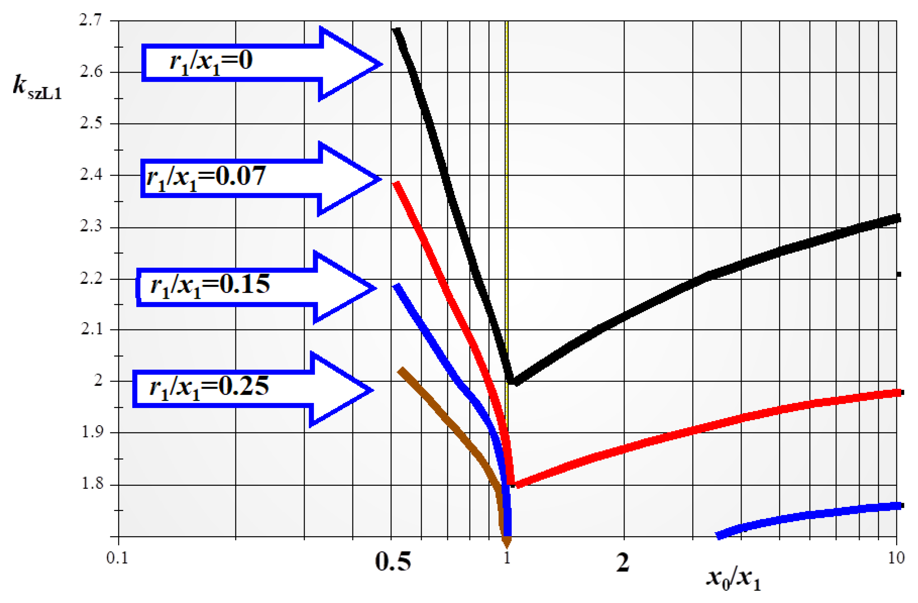
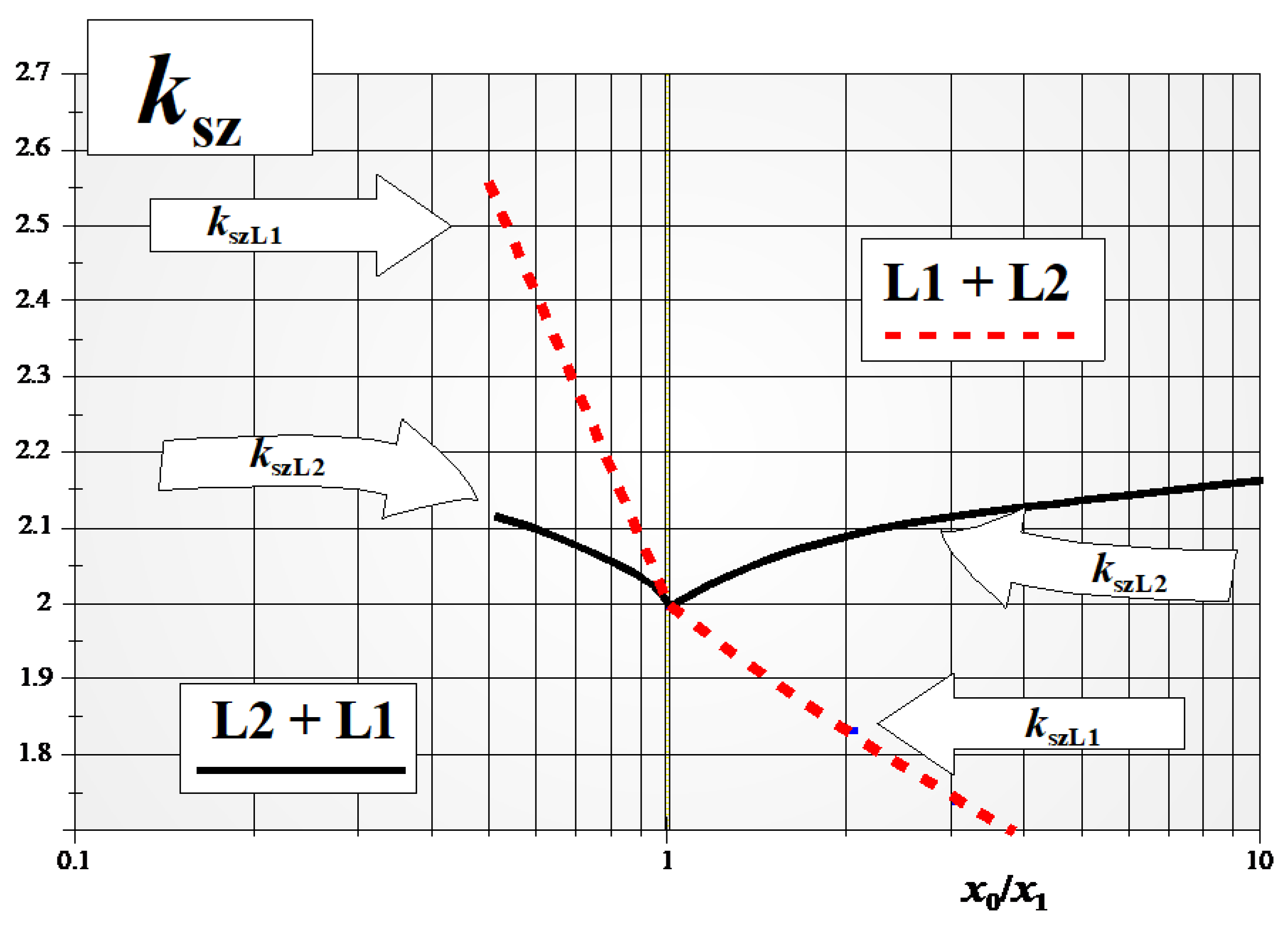
4.1. Peak Current Value Changes
- Single-phase turning into two-phase-to-ground fault.
- Three-phase with earth created in three stages:
- ▪
- Single-phase to two-phase to three-phase-to-ground.
- Three-phase-to-ground fault arising in two stages:
- ▪
- Simultaenous two-phase-to-ground to three-phase-to-ground or single-phase to three-phase-to-ground.
- Three-phase fault arising arising in two stages:
- ▪
- Two-phase simultaneous to three-phase.
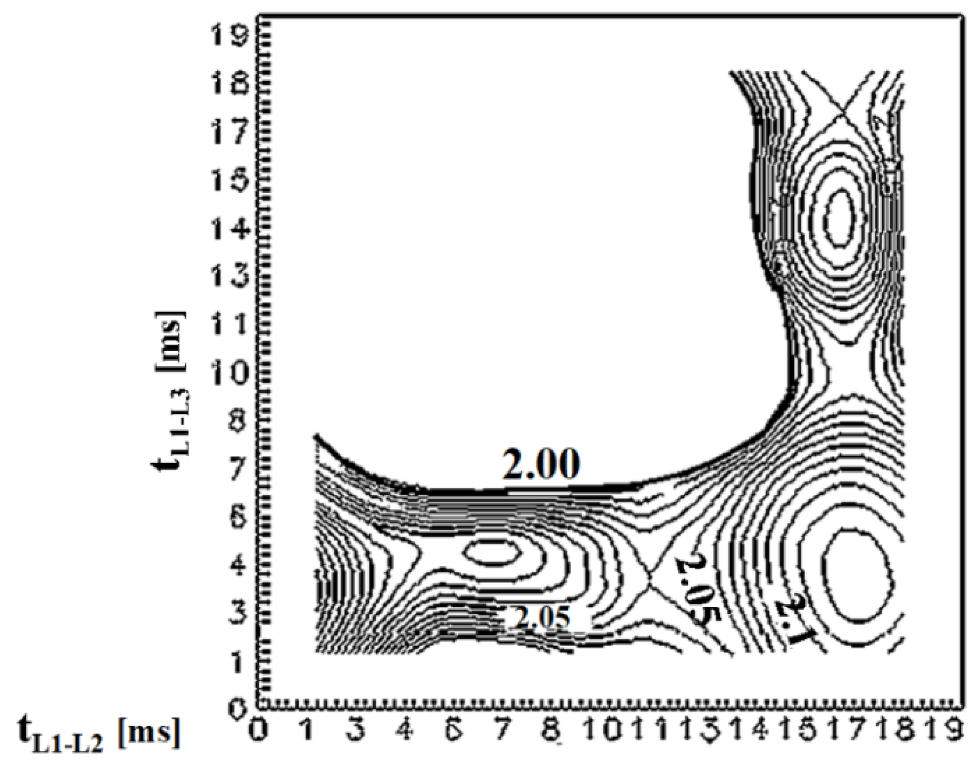
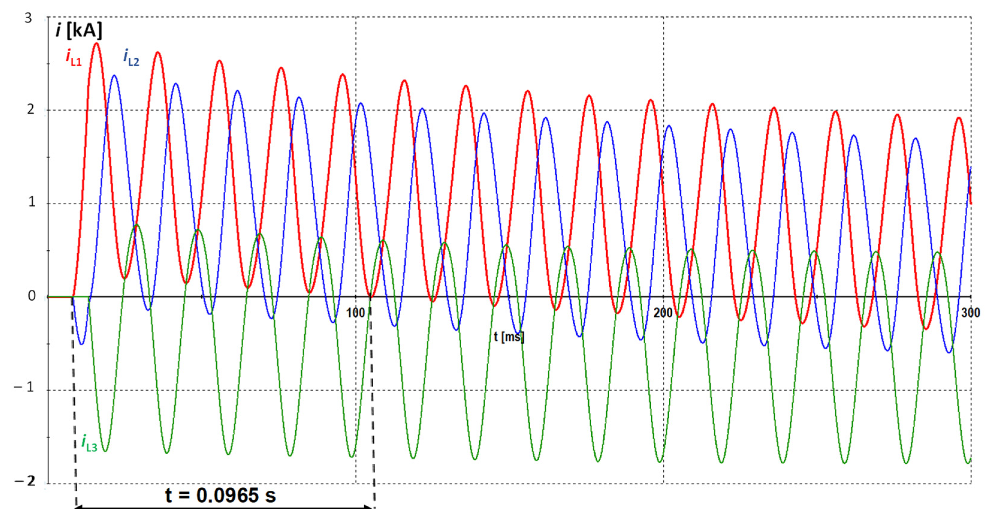
4.2. Delayed Current Zero during Non-Simultaneous Faults
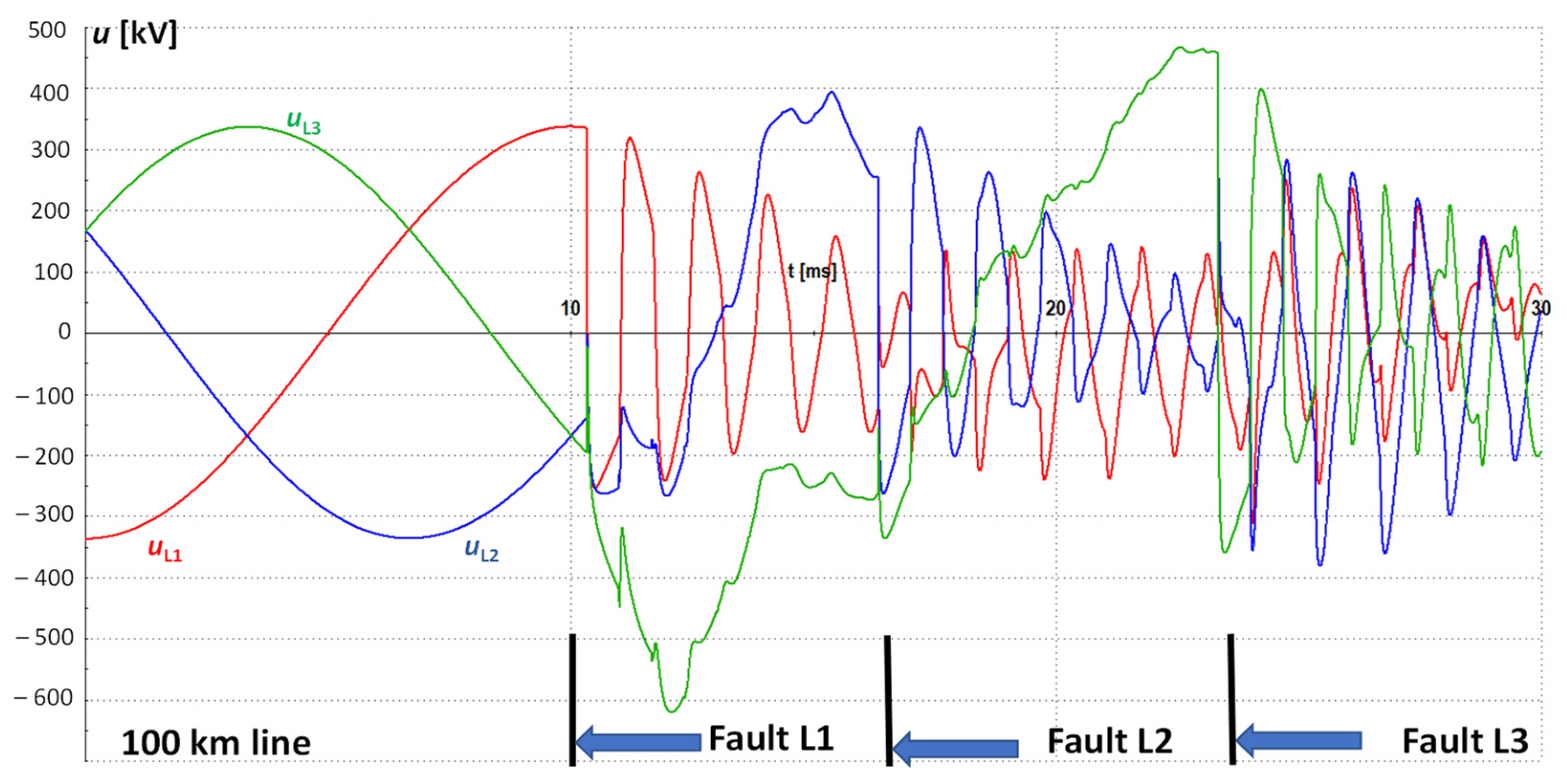
5. Overvoltages during Non-Simultaneous Faults
5.1. Preliminary Remarks
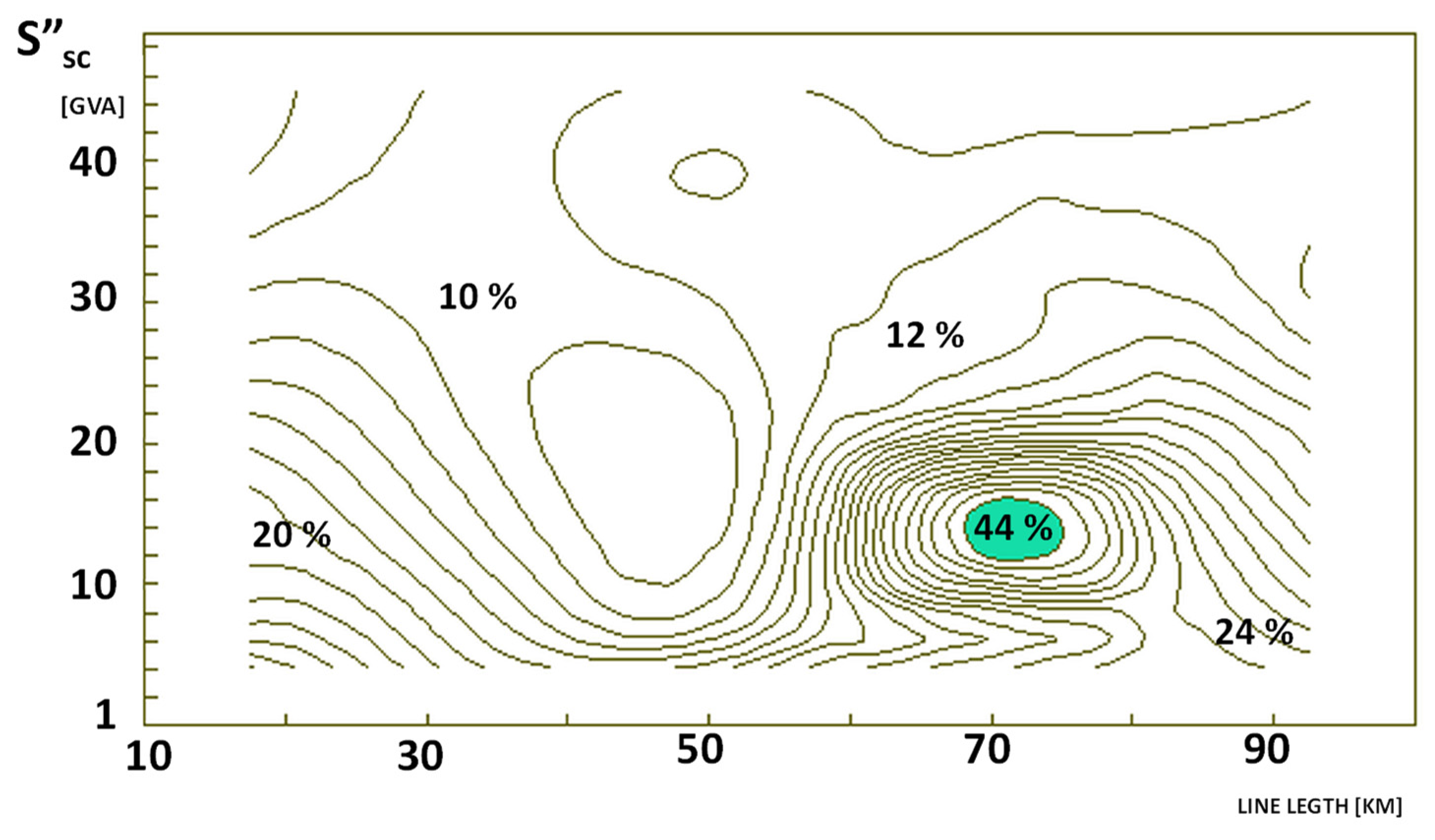
5.2. The Influence of the Non-Simultaneity of Faults
- Non-simultaneous three-phase-to-ground short circuits at the end of the line;
- Three-phase reconnection of the line (non-simultaneous and simultaneous on both sides) after the elimination of the fault;
- Three-phase reconnection of the line (non-simultaneous and simultaneous on both sides) with a permanent single-phase short circuit.
- Parameters and the structure of the system. The parameters of the transmission lines play a fundamental role, but also those of power supply systems, mainly the mutual impedance ratio for a zero and positive sequence as well as the resistance and reactance;
- The influence of the line load and system operating conditions (in a normal state) before the fault is negligible.
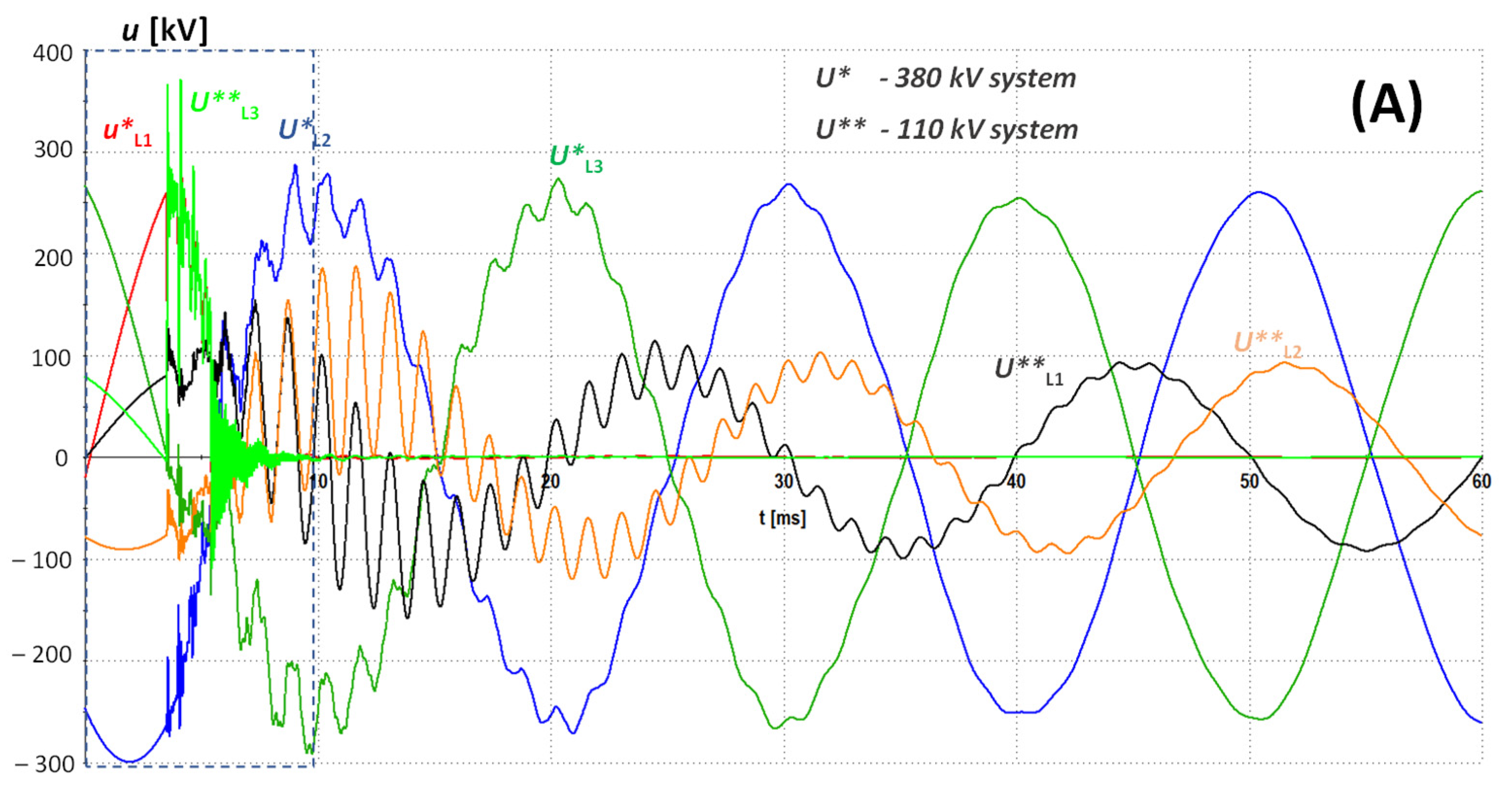
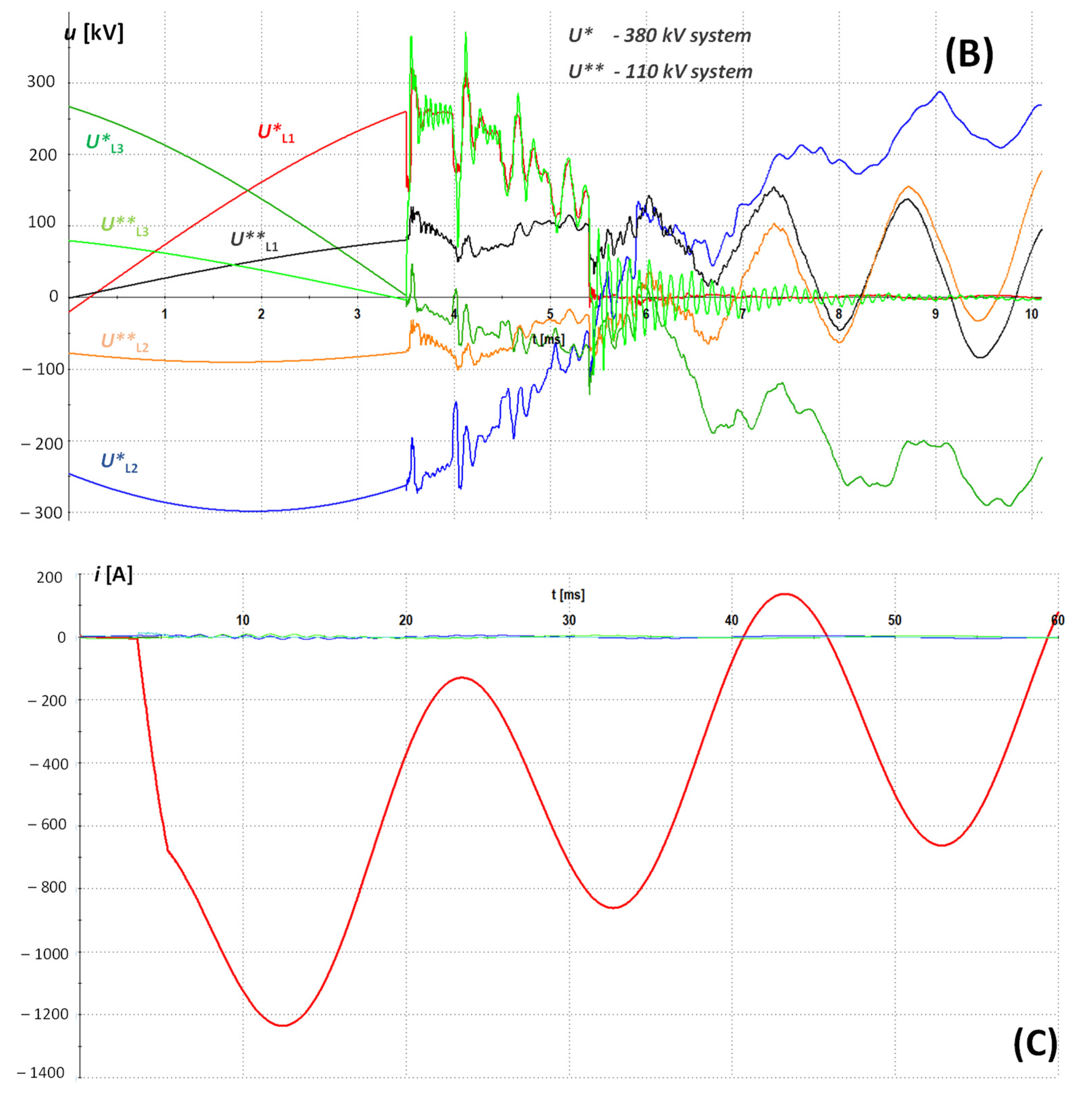
6. Overvoltages in Transmission Lines with Different Voltage Levels Operating on the Same Supporting Structures
7. Concluding Remarks
Author Contributions
Funding
Data Availability Statement
Conflicts of Interest
References
- Oswald, B.; Siegmund, D. Berechnung von Ausgleichsvorgängen in Elektroenergiesystemen; Deutscher Verlag für Grundstoffindustrie: Leipzig, Germany, 1991. [Google Scholar]
- Canay, M.; Werren, L. Interrupting sudden asymmetric short-circuit current without zero transition. Brown Boveri Rev. 1969, 56, 484–493. [Google Scholar]
- Canay, M.; Klein, H. Asymmetric short-circuit currents from generators and the effect of the breaking arc. Brown Boveri Rev. 1974, 61, 199–206. [Google Scholar]
- Owen, R.E.; Lewis, W.A. Asymmetry characteristics of progressive short-circuits on large synchronous generators. IEEE Trans. Power Appar. Syst. 1971, PAS-90, 587–596. [Google Scholar] [CrossRef]
- Kulicke, B.; Schramm, H.H. Clearance of Short-Circuits with Delayed Current Zeros in the ITAIPU 550 kV-Substation. IEEE Trans. Power Appar. Syst. 1980, PAS-99, 1406–1414. [Google Scholar] [CrossRef]
- Lim, L.S.; Smith, I.R. Turbogenerator shirt circuits with delayed current zeros. Proc. Inst. Electr. Eng. 1977, 124, 1163–1169. [Google Scholar] [CrossRef]
- Bogucki, A.; Sowa, P. Transiente Vorgänge während Kurzschlußfolgefehlern in Elektroenergiesystemen. In Proceedings of the 10. Wiss. Konf. der Sektion Elektrotechnik der TU Dresden, Dresden, Germany, 10–12 July 1984; pp. 45–49. [Google Scholar]
- Bogucki, A.; Sowa, P. Ströme und Kräfte bei kurzschlußartigen Folgefehlern. In Proceedings of the 31. Int. Wiss. Kolloquium, Ilmenau, H1, Ilmenau, Germany, 27–31 October 1986; pp. 7–10. [Google Scholar]
- Nordman, H. Current and forces in non-simultaneous three-phase short circuits. Sähkö 1974, 47, 82–86. [Google Scholar]
- Tsanakas, D. Ströme, Kräfte und mechanische Beanspruchung bei nicht gleichzeitig eintretenden Kurzschlüssen. etz-a 1975, 96, 501–505. [Google Scholar]
- Goto, M.; Nohara, H.; Takahashi, I.; Watanabe, A.; Kawai, T. Delayed Current-Zero Phenomena Caused by Transmission Line Faults. Trans. Inst. Electr. Eng. Jpn. B 1986, 106, 701–708. [Google Scholar] [CrossRef]
- Sowa, P.; Zychma, D. Dynamic Equivalents in Power System Studies: A Review. Energies 2022, 15, 1396. [Google Scholar] [CrossRef]
- Kulicke, B. Simulationsprogram Netomac: Differenzen-Leitwertverfahren bei kontinuierlichen und diskontinuierlichen Systemen. Siemens Forsch.-Und Entwickl. Ber Bd. 1981, 10, 299–302. [Google Scholar]
- Mahseredjian, J.; Dinavahi, V.; Martinez, J.A. Simulation Tools for Electromagnetic Transients in Power Systems: Overview and Challenges. IEEE Trans. Power Deliv. 2009, 24, 657–1669. [Google Scholar] [CrossRef]
- Ametani, A. Electromagnetic transients program: History and future. IEEJ Trans. Electr. Electron. Eng. 2021, 16, 1150–1158. [Google Scholar] [CrossRef]
- European EMTP User Group. ATP Rule Book; EEUG: Offenbach, Germany, 2007. [Google Scholar]
- Mahseredjian, J.; Dennetiere, S.; Dube, L.; Khodabakhchian, B.; Gerin-Lajoie, L. On a new approach for the simulation of transients in power systems. Electr. Power Syst. Res. 2007, 77, 1514–1520. [Google Scholar] [CrossRef]
- Dommel, H.W. EMTP Theory Book; Microtran Power System Analysis Corp: Vancouver, BC, Canada, 1992. [Google Scholar]
- Marti, J.R. Accurate modeling of frequency-dependent transmission lines in electromagnetic transient simulations. IEEE Trans. Power Appar. Syst. 1982, 101, 147–155. [Google Scholar] [CrossRef]
- Kocar, I.; Mahseredjian, J.; Olivier, G. Improvement of Numerical Stability for the Computation of Transients in Lines and Cables. IEEE Trans. Power Deliv. 2010, 25, 1104–1111. [Google Scholar] [CrossRef]
- Noda, T.; Nagaoka, H.; Ametani, A. Phase domain modeling of frequency-dependent transmission lines by means of an ARMA model. IEEE Trans. Power Deliv. 1996, 11, 401–411. [Google Scholar] [CrossRef]
- Castellanos, F.; Marti, J.R. Full frequency-dependent phase-domain transmission line model. IEEE Trans. Power Syst. 1997, 12, 1331–1339. [Google Scholar] [CrossRef]
- Carson, J.R. Wave propagation in overhead wires with ground return. Bell Syst. Tech. J. 1926, 5, 539–554. [Google Scholar] [CrossRef]
- Deri, A.; Tevan, G.; Semlyen, A.; Castanheira, A. The complex ground return plane, a simplified model for homogenoeous and multi-layer earth return. IEEE Trans. Power Appar. Syst. 1981, PAS-100, 3686–3693. [Google Scholar] [CrossRef]
- Siegmund, D.; Sowa, P. Zur Modellierung von Elektroenergieübertragungsleitungen mit konzentrierten Parametern―ein Vergleich zwischen digitaler und analoger Simulation. Wiss. Z. Der Tech. Univ. Dresd. 1987, 36, 97–102. [Google Scholar]
- Tavares, M.C.; Pissolato, J.; Portela, C.M. New multiphase mode domain transmission line model. Int. J. Electr. Power Energy Syst. 1999, 21, 585–601. [Google Scholar] [CrossRef]
- Jalali, F. Transmission Line Experiments at Low Cost. In Proceedings of the 1998 ASEE Annual Conference, Seattle, WA, USA, 28 June–1 July 1998. [Google Scholar]
- Portela, C.M.; Tavares, M.C. Six-Phase Transmission Line-Propagation Characteristics and New Three-Phase Representation. IEEE Trans. Power Deliv. 1993, 8, 1470–1482. [Google Scholar] [CrossRef]
- Carneiro, S.; Marti, J.R. Evaluation of corona and line models in electromagnetic transients simulations. IEEE Trans. Power Deliv. 1991, 6, 334–342. [Google Scholar] [CrossRef]
- Ishii, M.; Kawamura, T.; Kouno, T.; Ohsaki, E.; Shiokawa, K.; Murotani, K.; Higuchi, T. Multistory transmission tower model for lightning surge analysis. IEEE Trans. Power Deliv. 1991, 6, 1327–1335. [Google Scholar] [CrossRef]
- Bogucki, A.; Sowa, P. Transient Caused by Non-Simultaneous Arcing Faults. In Proceedings of the Sixth International Symposium on High Voltage Engineering, New Orleans, LA, USA, 28 August–1 September 1989. [Google Scholar]
- Cornick, K.J.; Ko, Y.M.; Pek, B. Power system transients caused by arcing faults. IEE Proc. C 1981, 128, 18–27. [Google Scholar] [CrossRef]
- Johns, T.; Al-Rawi, A.M. Digital Simulation of EHV systems under secondary arcing conditions associated with single-pole autoreclosure. IEE Proc. C 1982, 129, 49–58. [Google Scholar] [CrossRef]
- Hoseman, G. Berechnung der Kurzschlußströme und -kräfte in der Normung. etz-a 1976, 97, 298–303. [Google Scholar]
- IEC 60909-0:2016; Short-Circuit Currents in Three-Phase a.c. Systems–Part 0: Calculation of Currents. International Electrotechnical Commission: Geneva, Switzerland, 2016; ISBN 978-2-8322-3158-6.
- Błaszczyk, A.; Popczyk, J. Auswahl von 110-kV-Schaltern auf der Basis eines probabilistischen Modells. ELEKTRIE 1983, 5, 242–245. [Google Scholar]
- Ciok, Z. Non-simultaneous short-circuits in three-phase networks with special consideration to the effect upon operation of circuit-breakers. In Proceedings of the CIGRE, Paris, France, 16–26 May 1962. [Google Scholar]
- Hernandes, L.; Marques, F.Z.; Vasconcellos, A.S. Delayed current zeros in FPSO offshore units. In Proceedings of the 2014 IEEE Petroleum and Chemical Industry Conference—Brasil (PCIC Brasil), Rio de Janeiro, Brazil, 25–27 August 2014; pp. 147–154. [Google Scholar] [CrossRef]
- Eidinger, A. Interniption of high asymmetric short- circuit currents having long delayed zeros—An acute problem for generator breakers. IEEE Trans. PAS 1972, 91, 1725–1731. [Google Scholar]
- Braun, D.; Köppl, G.S. Transient Recovery Voltages During the Switching Under Out-of-Phase Conditions. In Proceedings of the International Conference on Power Systems Transients—IPST 2003, New Orleans, LA, USA, 28 September–2 October 2003. [Google Scholar]
- Vajnar, V.; Vostracky, Z. Reduced breaking capability of circuit breakers within operations with delayed current zeros. In Proceedings of the 2016 17th International Scientific Conference on Electric Power Engineering (EPE), Prague, Czech Republic, 16–18 May 2016; pp. 1–5. [Google Scholar]
- Ciok, Z. Einschwingspannung nach Abstandskurzschlüssen. ELEKTRIE 1981, 10, 552–553. [Google Scholar]
- Working Group 02 of Study Commitee 33. Guidelines for representation of network elements when calculating transients. CIGRE-Broch. 1990, 39. [Google Scholar]
- Johns, T.; Aggarwal, R.K. Digital simulation of faulted e.h.v. transmission lines with particular reference to very high-speed protection. Proc. Inst. Electr. Eng. 1976, 123, 353–359. [Google Scholar] [CrossRef]
- Boonybol, C. Power Transmission System Fault Simulation Analysis and Location. Ph.D. Thesis, University of Missouri, Columbia, MO, USA, 1968. [Google Scholar]
- Mahseredjian, J. Computation of power system transients: Overview and challenges. In Proceedings of the 2007 IEEE Power Engineering Society General Meeting, Tampa, FL, USA, 24–28 June 2007. [Google Scholar] [CrossRef]
- Cervantes, M.; Ametani, A.; Martin, C.; Kocar, I.; Montenegro, A.; Goldsworthy, D.; Tobin, T.; Mahseredjian, J.; Ramos, R.; Marti, J.R.; et al. Simulation of Switching Overvoltages and Validation with Field Tests. IEEE Trans. Power Deliv. 2018, 33, 2884–2893. [Google Scholar] [CrossRef]


| Parameter | Definition |
|---|---|
| S″sc = √3 UnI″sc | The (IEC standard [35]) short-circuit power |
| ku | Factor for the calculation of the peak short-circuit current by a simultaneous fault |
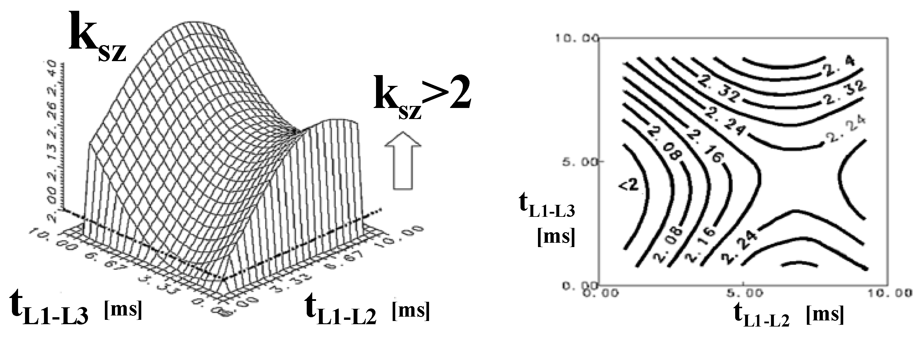
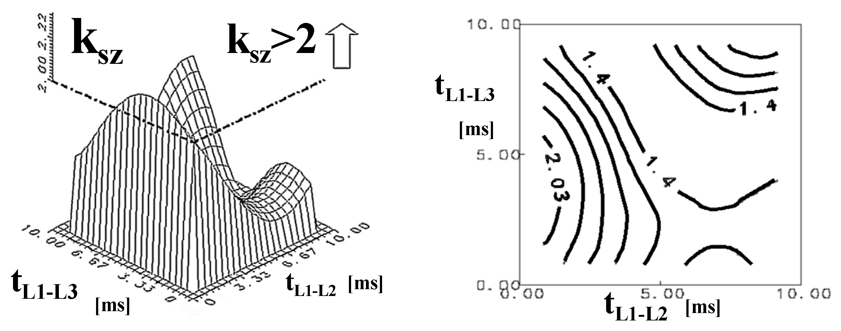
| ksz | The ratio of the peak current occurring in the case of a non-simultaneous fault to the amplitude of the periodic component at the time of the short circuit |
| r0 | Zero-sequence resistance |
| r1 | Positive-sequence resistance |
| x0 | Zero-sequence reactance |
| x1 | Positive-sequence reactance |
| xd″ | Subtransient reactance of a synchronous machine, direct axis |
| xq″ | Subtransient reactance of a synchronous machine, quadrature axis |
| Parameter | Value | Notes |
|---|---|---|
| The phase angle of the voltage at the time of the short circuit | 0 | Applies to all phases affected by the fault during a three-phase three-stage fault or a two-phase-to-ground fault and phases short-circuited separately during a three-phase two-stage fault for values x0/x1 < 1 |
| applies to phase-to-phase voltage during a three-phase two-stage short circuit for phases shorted simultaneously for the value x0/x1 > 1 | ||
| Delay time for short-circuiting subsequent phases during a non-simultaneous two-phase short-circuit to earth | 1.66 ÷ 5 ms | For x0/x1 > 1 and L2 + L1 short-circuit order |
| 5 ÷ 6.6 ms | For x0/x1 < 1 and L1 + L2 short-circuit order | |
| Delay time of successively phased short circuits during a non-simultaneous three-phase-to-ground short circuit | ≤6.6 ms | For x0/x1 < 1 and three-phase two-stage short circuit |
| ≤5 ms | For x0/x1 > 1 and three-phase two-stage short circuit | |
| r/x | 0 | Theoretically; in practice, the smallest value is 0.07 |
| Type of Fault | Three-Phase-to-Ground Short Circuit | Successful 3-Phase Reconnection | Successful 3-Phase Reconnection with a Permanent Single-Phase Short Circuit | |||
|---|---|---|---|---|---|---|
| Line Length (km) | Simultaneous | Non-Simultaneous | Simultaneous | Non-Simultaneous | Simultaneous | Non-Simultaneous |
| 10 | 1.02 | 1.69 | 1.69 | 1.69 | 1.69 | 1.69 |
| 30 | 1.03 | 1.76 | 1.76 | 1.76 | 1.76 | 1.76 |
| 50 | 1.08 | 1.71 | 1.71 | 1.71 | 1.71 | 1.71 |
| 70 | 1.16 | 2.02 | 2.02 | 2.02 | 2.02 | 2.02 |
| 100 | 1.25 | 1.90 | 1.90 | 1.90 | 1.90 | 1.90 |
| 250 | 1.32 | 2.21 | 1.33 | 2.17 | 1.12 | 2.23 |
| Line (kV) | Type of Short Circuit | L1 Phase | L2 Phase | L3 Phase |
|---|---|---|---|---|
| 110 | L1 + g | 2.72 | 1.88 | 1.83 |
| L1 + L2 | 1.81 | 1.67 | 1.91 | |
| L1 + L2 + g | 2.72 | 1.90 | 2.03 | |
| L1 + L2 + L3 (simultaneous) | 1.49 | 1.27 | 1.68 | |
| 380 | L1 + L2 + L3 + g (non-simultaneous) | 2.72 | 1.90 | 2.19 |
| L1 + g | 1.06 | 1.05 | 1.14 | |
| L1 + L2 | 1.34 | 1.44 | 1.09 | |
| L1 + L2 + g | 1.05 | 1.05 | 1.14 |
Disclaimer/Publisher’s Note: The statements, opinions and data contained in all publications are solely those of the individual author(s) and contributor(s) and not of MDPI and/or the editor(s). MDPI and/or the editor(s) disclaim responsibility for any injury to people or property resulting from any ideas, methods, instructions or products referred to in the content. |
© 2023 by the authors. Licensee MDPI, Basel, Switzerland. This article is an open access article distributed under the terms and conditions of the Creative Commons Attribution (CC BY) license (https://creativecommons.org/licenses/by/4.0/).
Share and Cite
Sowa, P.; Zychma, D. Identification of Free Components during Non-Simultaneous Complex Faults in Overhead Lines: A Review. Energies 2023, 16, 6618. https://doi.org/10.3390/en16186618
Sowa P, Zychma D. Identification of Free Components during Non-Simultaneous Complex Faults in Overhead Lines: A Review. Energies. 2023; 16(18):6618. https://doi.org/10.3390/en16186618
Chicago/Turabian StyleSowa, Paweł, and Daria Zychma. 2023. "Identification of Free Components during Non-Simultaneous Complex Faults in Overhead Lines: A Review" Energies 16, no. 18: 6618. https://doi.org/10.3390/en16186618
APA StyleSowa, P., & Zychma, D. (2023). Identification of Free Components during Non-Simultaneous Complex Faults in Overhead Lines: A Review. Energies, 16(18), 6618. https://doi.org/10.3390/en16186618