Article

Performance Validation of Resonant Wave Power Converter with Variable Moment of Inertia

1
Department of Civil Engineering, Kunsan National University, Gunsan 54150, Republic of Korea
2
Division of Mechanical and Automotive Engineering, Hoseo University, Asan 31499, Republic of Korea
*
Author to whom correspondence should be addressed.
Energies 2023, 16(18), 6617; https://doi.org/10.3390/en16186617
Submission received: 21 August 2023 / Revised: 6 September 2023 / Accepted: 13 September 2023 / Published: 14 September 2023
(This article belongs to the Section A3: Wind, Wave and Tidal Energy)

Abstract

:
This study focuses on the performance validation of a wave energy converter (WEC) equipped with resonant frequency adjustment capability. Achieving resonance with the oscillation period of waves is crucial for maximizing the efficiency of wave energy conversion systems. For this purpose, we introduce a variable moment of inertia (VMI) device that allows for tuning of the resonant frequency by adjusting the position of the mass. For validation of the proposed approach, performance verification experiments were conducted using a vibration platform. Through free vibration experiments, we identified the system’s resonant frequency and characteristics. In our forced vibration tests considering the wave frequency band of the coastal area, harmonic vibration experiments were performed over a range of 0.4–0.8 Hz. In these experiments, we considered three separate cases by adjusting the distance from the reel’s center to the mass. As a result, we found that the resonant frequency of the WEC can be adjusted from 0.65 Hz when the mass is furthest away to 0.55 Hz when it is closer. This research confirms the benefits obtained by utilizing VMI to adjust the resonant frequency of WECs without changing the mass or springs. This offers a promising opportunity to enhance the energy conversion efficiency of resonant-type WECs utilizing wave energy.

1. Introduction

Addressing climate change through global efforts and the expansion of renewable energy sources is one of the most critical challenges in modern society. Climate change is causing unstable phenomena such as rising global temperatures, extreme weather patterns, sea-level rise, and ecosystem changes which have significant impacts on the environment, economy, and society.
Countries around the world recognize the severity of climate change and are striving for environmental protection and sustainable development. Through international collaborations such as the Paris Agreement, greenhouse gas reduction targets have been set and ongoing monitoring and reporting track progress. Investments are being made in eco-friendly technologies and energy efficiency, thereby strengthening environmental responsibility.
Renewable energy plays a pivotal role in addressing climate change. Renewable energy resources such as solar, wind, hydro, geothermal, and tidal power enable a reduction in greenhouse gas emissions and promote environmentally friendly energy production. According to Enerdata, a firm specializing in energy and climate analysis and forecasting, the share of renewable energy in the global power mix has increased from 20% in 2010 to 30% in recent years. Among these, wind, solar photovoltaic, and solar thermal power capacities have been steadily increasing, accounting for approximately 12.2% of the world’s power mix in 2022 [1].
Furthermore, there has been significant development in harnessing wave energy, a vast energy source that has the potential to produce approximately 2 terawatts (TW) of electricity annually [2]. However, current wave energy systems are limited to specific locations and have not yet achieved a competitive levelized cost of energy (LCOE) [3]. Therefore, there is a need for more efficient mechanisms to extract energy from waves and produce electricity reliably in order boost its commercial viability.
One of the primary challenges in wave energy conversion research is achieving optimal performance and efficiency. Wave energy conversion devices utilizing resonance systems can produce their most electrical power levels and operate at high efficiency when the frequency of incoming waves matches the system’s resonant frequency. However, in the natural state ocean waves continually change their frequency due to environmental factors such as winds, tides, etc. This frequency variability poses a significant obstacle to achieving and maintaining resonance in practical wave energy conversion systems.
Numerous studies have been conducted on the response and resonance of structures subjected to wave action. Research has been carried out to enhance the safety of vessels by investigating parametric roll motion under resonance conditions, and significant motion has been reported through numerical analysis and experiments [4,5,6]. Additionally, it has been confirmed that nonlinear resonance can occur in wave–structure interaction systems during the presence of large waves [7]. It has been observed that temporary fluid resonance occurs between two structures in close proximity [8,9,10]. While leveraging these resonance phenomena can lead to greater energy harvesting, wave energy converters (WECs) require mechanisms for stable energy extraction even in everyday wave conditions.
WECs are primary used in the form of oscillating bodies or moving bodies designed to respond sensitively to wave action by utilizing buoyancy that allows them to float or submerge in the ocean. Various types of oscillating WEC technologies have been explored to maximize the energy harvested from wave power generation [11,12,13,14,15,16,17,18]. Oscillating body WECs mainly deal with two resonant phenomena: buoy resonance, corresponding to the buoy’s response to wave input, and inner vibrating system resonance. In this study, we specifically focus on the resonance of the vibrating system within the buoy. Several studies have aimed to harness the resonant capabilities of the inner vibrating system in wave power generation systems [19,20,21]. These studies propose mass–spring systems that synchronize the wave period with the resonant frequency of the inner vibrating system to enhance the efficiency and energy harvesting capacity of WECs. The construction of a mass–spring system that resonates with relatively low-frequency waves in wave energy conversion presents many challenges, as it requires either increasing the mass or reducing the stiffness of the spring. Additionally, increased system size is required due to the initial static deflection of the spring.
To overcome these issues, Jang et al. [22] proposed the yo-yo vibrational energy harvesting system, which utilizes helical springs and generators to convert the vertical motion of the mass–spring system into rotational motion of the reel. It has been confirmed that the resonant frequency can be adjusted by varying the radius of the reel. Being able to adjust the resonant frequency without changing the mass or spring is a significant advantage. Additionally, the motion being converted into rotational movement allows for the utilization of relatively optimized power generation systems such as motors without the need to consider the initial static deflection caused by the mass. Recognizing these advantages, subsequent studies have applied this system in wave energy conversion systems considering variable stiffness and using serially-connected multiple springs [23] and oblique springs [24] Similarly, the advantages of yo-yo energy harvesting systems with adjustable resonant frequency are applied in our present research.
In this study, a variable moment of inertia (VMI) device is applied to the WEC. By adjusting the position of the mass inside the converter, the VMI device can change the system’s natural frequency, allowing it to adapt to different wave conditions and maintain resonance in order to maximize energy capture [25]. The proposed device has merit in that it can be easily implemented and applied in real-world applications, as it does not manipulate the constituent values or sizes of the reels in the yo-yo vibrational energy harvester. The period of waves varies under the influence of various environmental factors, ranging from a few seconds to 20 s in deep oceans and from 1 s to less than 5 s in shallow seas [26,27]. In this study, considering the stroke limitation of the experimental setup, the proposed system is designed to have a period under 2 s. We investigate the effect of varying the moment of inertia on the system’s resonant behavior and efficiency. The numerical calculations and free vibration experiments were conducted to analyze the developed system’s resonant frequency; in addition, forced vibration experiments were performed using a shaking table. Increasing the moment of inertia using the VMI may reduce the power performance of the WPC. Based on our investigation of the effect of the VMI, we propose an enhanced power generation system that can compensate for this drawback.
The rest of this paper is organized as follows. In Section 2, the overall concept and theoretical studies of WEC using VMI are presented. Section 3 discusses the tuning and power performance of the proposed device based on the results of free and forced vibration experiments. Finally, our conclusions based on these findings are presented in Section 4.

2. Wave Energy Converter with Variable Moment of Inertia

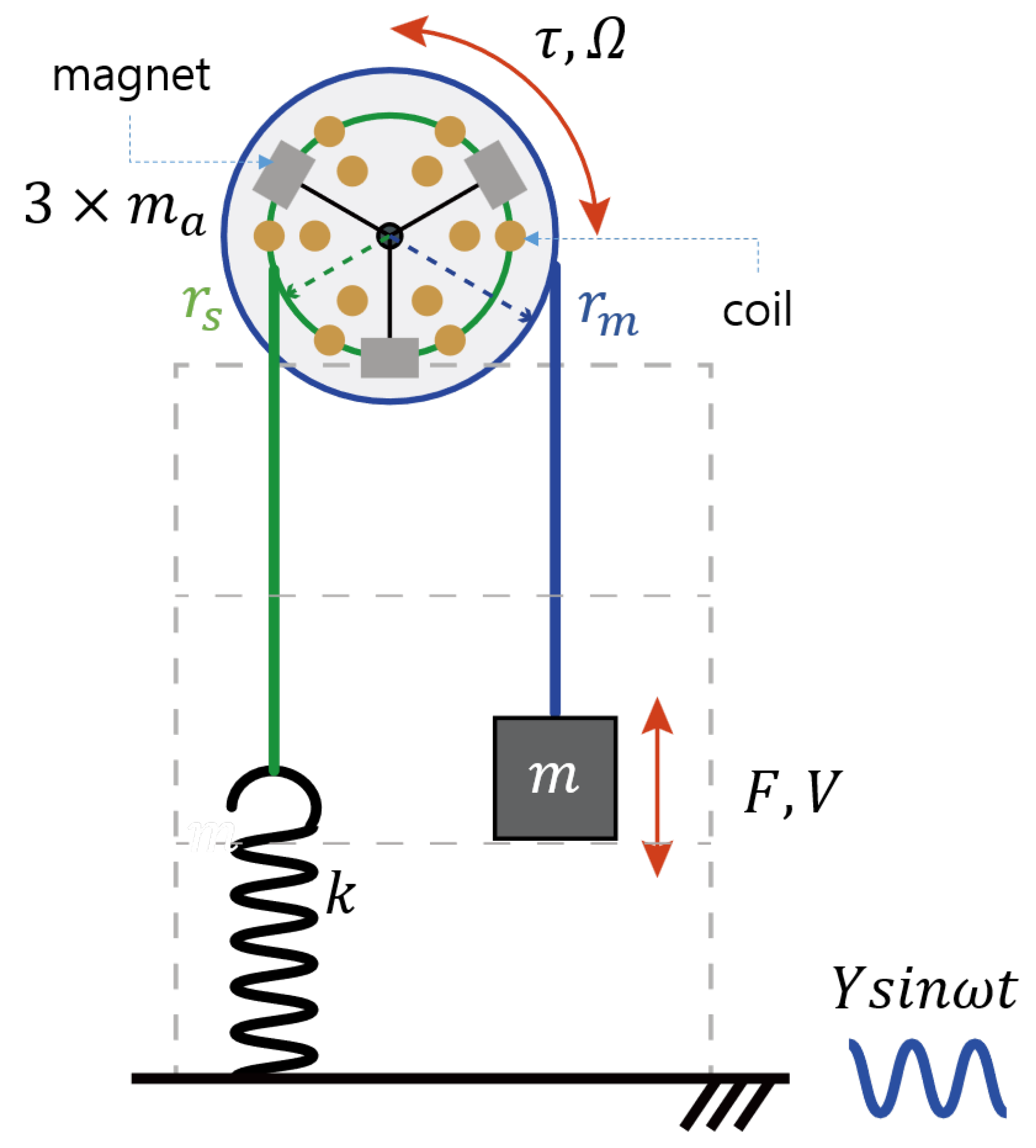
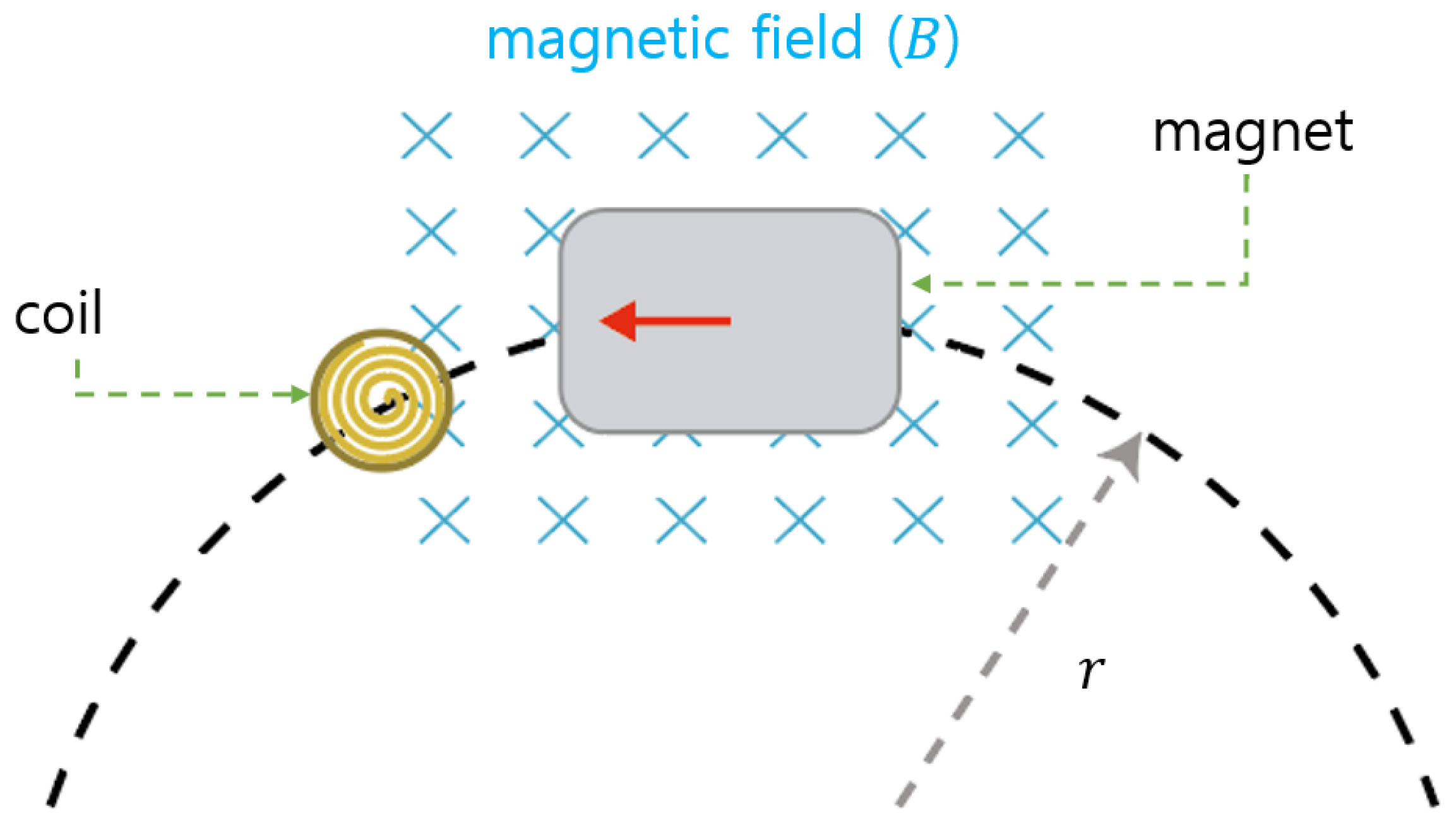
2.1. System Modeling

The schematic diagram of the yo-yo type WEC integrated with VMI to tune the resonant frequency is presented in Figure 1. The system comprises a mass, spring, reels, and a generator. Wires connect the mass and spring to reels of different radii, transforming vertical vibrations into rotational motion. The radii of the reels connected to the mass and the spring are designated as r m and r s , respectively. The spring’s stiffness is denoted by k, and the mass is represented by m. The impedances for the translational and rotational components are as follows [25]:
F V = j ω m
τ Ω = k r s 2 j ω + c + j ω J
where F and V denote the external force acting on the proof mass and its velocity, respectively, τ and Ω signify the torque applied to the reel axis and its rotational velocity, respectively, the coefficient c is the damping coefficient, J represents the integrated moment of inertia of the rotating component, and ω strands for the base excitation frequency. Considering that the torque acting on the reel and the displacement of the mass can be respectively described by r m F and r m Ω , combining the impedances in Equation (2) in parallel results in the total impedance of the system. When the base excitation amplitude is defined as Y and the excitation force at the proof mass is F = m Y ω 2 s i n ω t , the rotating velocity of the reel can be determined as follows:
| Ω | = m r m Y ω 3 ( k r s 2 ω 2 ( m r m 2 + J ) ) 2 + ω 2 c 2 .
The resonant frequency of the proposed device can be modified by the VMI system. The integrated moment of inertia of the rotation system, denoted by J, is redefined by incorporating the auxiliary masses. The resonant frequency of the system when taking the VMI system into account can be described as follows:
f = 1 T = γ s 2 π k m + J 0 r m 2 + i = 1 n m a , i γ a 2
where T denotes the period, n is the total auxiliary mass, J 0 stands for the moment of inertia of the reel component, ρ signifies the distance from the reel’s center to the auxiliary mass γ a = ρ / r m , and γ s represents the ratio between the rotational radius of the spring ( r s ) and the rotational radius of the mass ( r m ). As a result, the resonant frequency of the WEC can be fine-tuned based on the geometric parameters γ s and γ a along with the mass-to-stiffness ratio. Although there are inherent properties in the proposed system, namely, the mass, stiffness, and reel radii, which can alter the resonant frequency, it is more feasible to use the VMI device for adjusting the resonant frequency through γ a . Comprehensive explanations of the equations can be found in the reference materials [25].

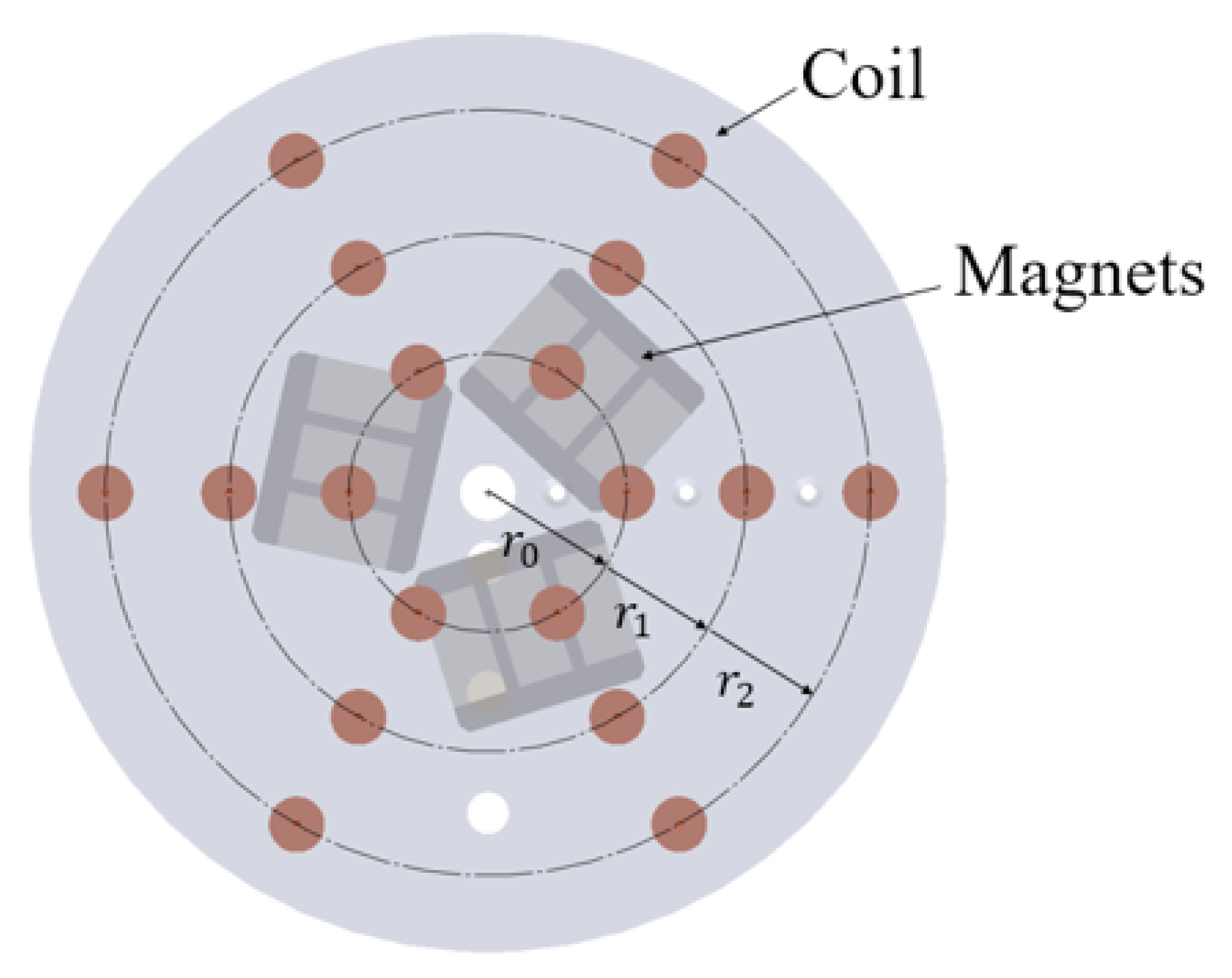
2.2. Design of Power Generation System

In the preceding section, we have explained the schematic and dynamics of the proposed device. Electrical power is extracted from the energy harvester attached to the reel assembly. In this section, we estimate the power produced by the energy harvesters in the yo-yo vibrating system and investigate their characteristics. The generated power can be influenced by VMI. We propose an enhanced power generation system that can compensate for the effects of VMI.
Figure 2 shows a magnet attached to a reel of the WEC and a single circular coil. In this setup, the coil remains stationary and only the magnet rotates. As the coil enters the magnetic field region B of the magnet, the magnitude of the voltage is proportional to the rate of change of the area the coil traverses. Although this magnetic field is not uniform, due to the very short distance between the coil and magnet it can be simplified to the magnitude near the magnet’s surface. The magnet, being attached to the rotating frame of the reel, rotates at a constant angular velocity Ω with a rotational radius r. As a result, the circular coil generates its maximum voltage when the magnet passes through its center, where the rate of area change is at its peak. The maximum voltage produced from a single coil is expressed by the following equation [28,29,30]:
v = N B l r Ω
where N, B, and l represent the number of turns in the coil, the magnitude of the magnetic field, and the diameter of the coil, respectively. The maximum power output can be calculated from Equation (6):
P = v 2 R = N 2 B 2 l 2 r 2 m 2 Y 2 r m 2 ω 6 R ( ( k r s 2 ω 2 ( m r m 2 + J 0 + i = 1 n m a , i ρ 2 ) ) 2 + ω 2 c 2 )
where R is the magnitude of the load resistance. Letting J 0 = 0 and introducing dimensionless variables, Equation (6) can be expressed in simplified form as follows:
P = A ω 2 ω n 4 [ ( 1 ω 2 ω n 2 ( 1 + μ γ a 2 ) ) 2 + ( 2 ζ ω ω n ) 2 ] 1
where A = N 2 B 2 l 2 r 2 a 2 R , a = Y ω 2 , ω n = γ s k m , μ = i = 1 n m a , i m , and ζ = c 2 m r m 2 ω n . Because the magnitude of the acceleration a is constant, the value of A is constant as well, and is manipulated here to find the normalized maximum power output. The parameters used in the numerical model are shown in Table 1, while Figure 3 shows the normalized output power calculated from the numerical analysis.
In the numerical model, the calculated resonant frequencies are found to be 0.671, 0.64, and 0.597 Hz when ρ is 0.05, 0.093, and 0.1375 m, respectively. Therefore, by increasing the size of the auxiliary mass or positioning it farther from the center of the reel, the resonant frequency can be lowered. Figure 3 illustrates the frequency changes of the system according to the variations in ρ . In the figure, the x-axis represents the frequency and the y-axis shows the normalized output magnitude, which is set to 1. In energy harvesting systems, not only is it important to adjust the resonant frequency, the bandwidth is key to the efficiency power generation. The bandwidth of a dynamic system is typically verified at 70% of the output, which is the level of −3 dB from the peak value. In the proposed system, it can be observed that the bandwidth at ρ = 137.5 mm is reduced by 20.7% compared to that at ρ = 50 mm. This can negatively impact the device’s output in constantly changing sea conditions. To address this issue, in this study we propose the enhanced power generation system shown in Figure 4.
The power generating system positions multiple coil arrays at varying distances from the reel’s center. In this study, three rows of coils are placed at distances of 50, 93, and 137.5 mm from the reel’s center, with permanent magnets attached to the auxiliary masses. This configuration enables efficient power production by generating a varying electromagnetic field as the rotation causes interaction with the coils. If the relationship r = ρ is satisfied, the generated voltage, which varies based on the position of the auxiliary masses, can be derived from Equations (3) and (5) as follows:
v = N B l a ( ω ω n 2 ) γ a ( 1 ω 2 ω n 2 ( 1 + μ γ a 2 ) ) 2 + ( 2 ζ ω ω n ) 2 .
From Equation (8), it is evident that the generated voltage is proportional to the ratio γ a of the radius. Thus, as the position of the auxiliary mass increases, the voltage output increases with it. This can compensate for the reduced output power bandwidth resulting from the shift in the position of the auxiliary masses.

3. Experimental Validation

In this section, we describe the experiments used to verify the performance of the WEC with VMI. First, we describe the proposed system and the experimental setup. Next, we discuss the results of the free vibration experiments conducted to understand the characteristics of adjusting the system’s resonant frequency using VMI. Lastly, we discuss the results of the forced vibration experiments carried out using a vibration table. Additionally, in the forced vibration experiments we examine the generation of power through energy harvesting.

3.1. Experimental Setup

The WEC with VMI and the experimental setup are illustrated in Figure 5. Taking into consideration the connection to the shaking table and the movement of the mass, a jig was fabricated. The WEC, including the VMI and power generation components, was installed on the rig. The proof mass and spring were connected to reels with different rotational radii using wires. The power generation unit comprised three rows of coils arranged in a circular pattern, with a set of neodymium permanent magnets affixed to the auxiliary masses. The specifications for the coils and permanent magnets employed in the power generation unit are detailed in Table 2. The proof mass generates power as it oscillates due to the vibrations of the WEC, and the system’s resonant frequency can be modulated by adjusting the positions of the three auxiliary masses. In the experiments, the weights of the proof mass (m) and one auxiliary mass ( m a ) were 15.75 kg and 2.1 kg, respectively. Furthermore, the rotational radii for the mass reel ( r m ) and spring reel ( r s ) were designed to be 0.155 m and 0.050 m, respectively. Lastly, the spring stiffness k was set at 2800 N/m. The system was mounted on a vertical shaking table and received inputs with a predetermined frequency and amplitude through a separate controller. To mitigate the impact of initial vibration shocks during experiments, a tapered sine was considered. For the purpose of validating the performance of the proposed system, an encoder (AUTONICS, E50S8-100-3-T-1, Busan, Republic of Korea) and a data acquisition device (National Instruments, NI PXIe-1071, Austin, TX, USA) were used to obtain angular velocity measurements. A digital power meter (Yokogawa, WT330, Tokyo, Japan) and a load resistor of 10 Ω were connected to the coil to measure the voltage induced by electromagnetic induction.

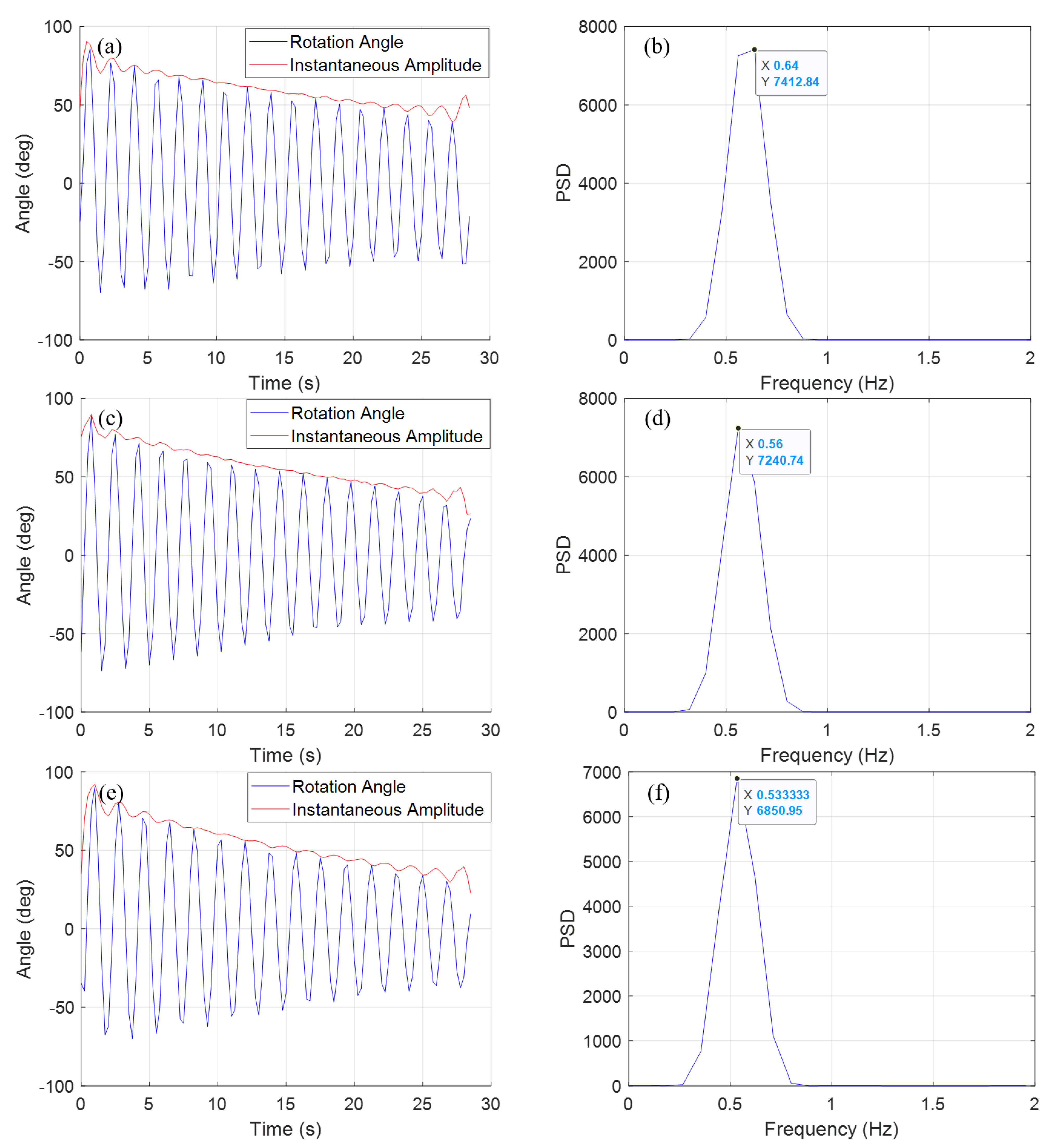
3.2. Free Vibration Test

In the free vibration experiment, the proof mass was first forced to move to a specific displacement, then the load was released. Vibration measurements were taken using the encoder attached to the reel, as shown in Figure 6. Considering the resonant frequency of the system, the sampling frequency of the encoder in the free vibration experiments was set to 4 Hz. From the time history results of the free vibration tests, the Hilbert transform was used to calculate the damping ratio when the value of ρ changed [31,32,33]. The Hilbert transform is a well-known tool in vibration analysis, and is widely used in fields such as mechanical engineering [34] and structural engineering [35,36]. It calculates the instantaneous amplitude and frequency of system responses as a function of time. This information can then be used to compute instantaneous damping coefficients and natural frequencies. Because the Hilbert transform is well-known in terms of its application in damping ratio estimation, we have presented only the instantaneous amplitude obtained alongside the time history results in this paper, excluding the process of deriving equations and calculating parameters. The calculated damping ratios were 0.0066, 0.0102, and 0.0119 for distances ρ of 50 mm, 93 mm, and 137.5 mm, respectively. All of these have low damping ratios, and it was found that the damping ratio falls together with the distance ρ .
Finally, the power spectral density was computed using the pwelch method [37] to observe how the resonant frequency changes with varying ρ . The resonant frequencies of the system corresponding to different values of ρ are shown in Figure 6b,d,f. In the frequency domain, the values were observed to be 0.64 Hz, 0.56 Hz, and 0.53 Hz for ρ of 50 mm, 93 mm, and 137.5 mm, respectively. The observed resonant frequencies had differences of around 10% from the numerical calculations, which can be attributed to the lack of precise measurement data and unconsidered inertia in the numerical calculations. In reality, the frequency change rates were found to be in a similar range to the numerical calculations.

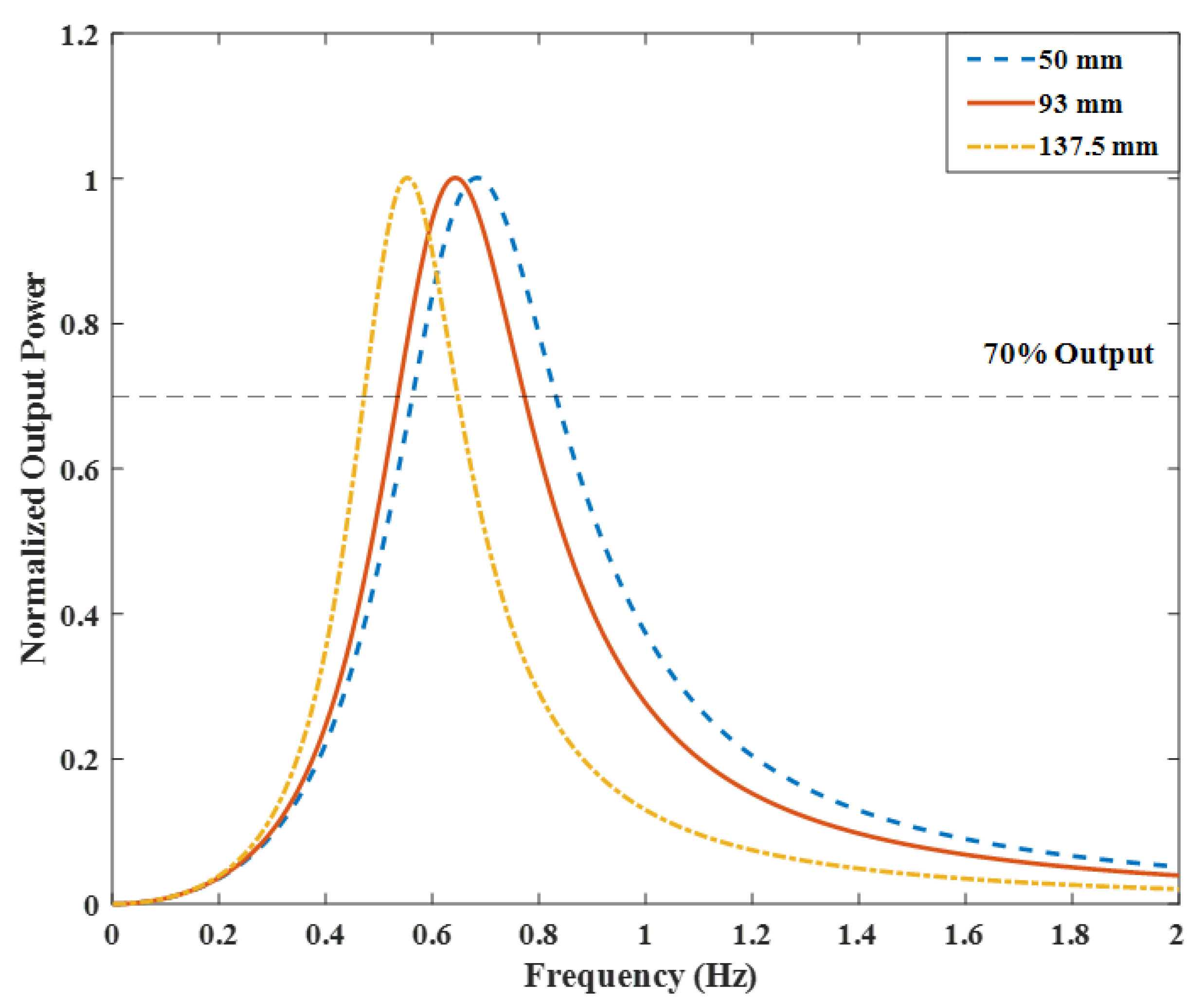
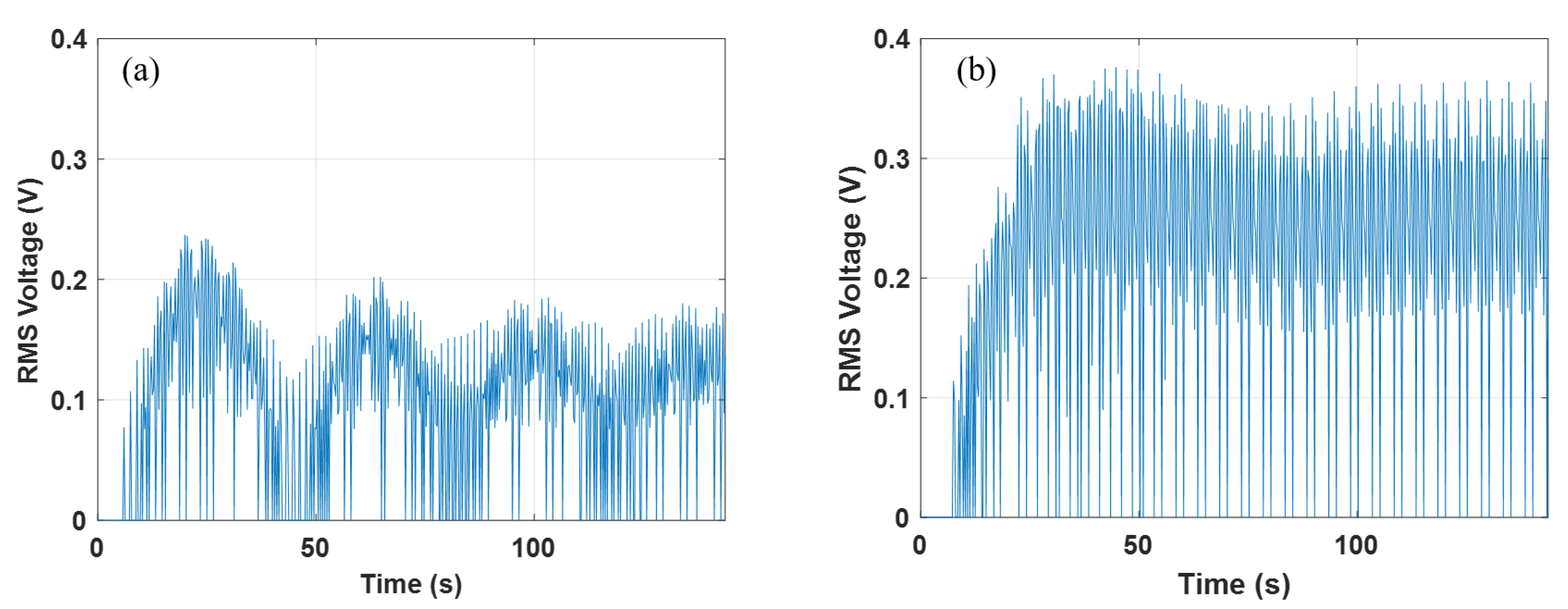
3.3. Forced Vibration Test

The forced vibration experiments used a vertical shake table. To understand the dynamic behavior and validate the performance of the WEC with VMI, we employed sine wave excitation with a constant acceleration of 0.02 g (0.1962 m/s 2 ). Figure 7 illustrates the variation of the system’s resonant frequency when using VMI as measured by an encoder connected to the reel. The markers represent the actual maximum angle measured, while the lines depict the results obtained from 1D linear interpolation of these data.
Forced vibration experiments were carried out in the range of 0.4–0.8 Hz, taking into account the resonant frequencies determined through analysis. The frequency interval was set at 0.05 Hz. The results indicate that the resonant frequencies change with the position of the auxiliary masses, which is consistent with both the numerical calculations and the free vibration test results.
Finally, the voltage generated by the rotational motion of the WEC was measured, as shown in Figure 8. The instrument utilized for voltage measurement was the same power meter outlined in Section 3.1. Of the three measurement modes—RMS, voltage mean, and DC—the RMS mode was selected. This was determined using the following equation after the voltage had been measured [38]:
v r m s = 1 T 0 T f ( t ) 2 d t
where f ( t ) is the originally measured input signal and T represents one period of this signal. The power meter automatically calculated T based on the measured signal and then computed the RMS voltage. Because the equation involves squaring the input voltage and integrating over one period, the resulting RMS voltage always has a positive value. As shown in Equation (8), the generated voltage varies with γ a . In the forced vibration experiment, RMS voltage measurements were conducted for two cases: r ( = ρ ) 50 mm and r ( = ρ ) 93 mm. It should be noted that these data were obtained at their respective resonant frequencies, i.e., 0.65 and 0.6 Hz. The results reveal that a larger RMS voltage was generated when the distance was 93 mm compared to when it was 50 mm. This can be attributed to the principle of electromagnetic induction; a higher inlet speed leads to higher voltage, and in this case the higher tangential speed associated with the magnets, which were at a distance pf 93 mm from the center, resulted in a higher output voltage.

4. Conclusions

In this study, we have explored the application of VMI for resonance frequency control of the WEC and verified its performance. WECs using an internal resonance system achieve optimal power generation efficiency when the system’s resonance frequency aligns with the wave period. Research on yo-yo type WECs, which transform the vertical motion of waves into rotational movement, has been ongoing. Converting vertical movement to rotational movement allows for the application of relatively optimized generators while eliminating the need to enlarge the entire system due to static sagging caused by the proof mass.
The VMI system considered in this study adjusts the resonance frequency by changing the distance between the center of the reel and the auxiliary mass. This method offers the advantage of not having to adjust the size of the mass or the stiffness of the spring for resonance frequency control. Especially for low-frequency ranges such as waves, adjusting the resonance frequency typically requires larger mass and lower stiffness, making production challenging; the VMI system proposed in this paper addresses this issue.
We evaluated the power production of the VMI-equipped WEC using numerical models and verified its performance through both free vibration and forced vibration tests. In the numerical model, we confirmed that VMI effectively adjusts the system’s resonance frequency. However, when tuned to a lower frequency we observed that the power-generating frequency bandwidth at −3 dB decreased. To overcome this, the system’s power generation section was composed of three rows of coils arranged in a circle and a set of neodymium permanent magnets was assembled on the auxiliary mass. In the free vibration tests, we observed changes in the resonance frequency due to VMI, and found that the system’s resonance frequencies for a ρ of 50 mm, 93 mm, and 137.5 mm are 0.64 Hz, 0.56 Hz, and 0.53 Hz, respectively. This represents a discrepancy of about 10% compared to our numerical calculations, presumably due to the inertia not being considered in the calculations. Moreover, the rate of frequency change was found to be in a range similar to that of the numerical calculations. When using the Hilbert transformation in our free vibration tests, we observed that the damping ratio grew as ρ increased. Forced vibration tests were conducted using a jig installed on a vibration table. The test setup applied a sine wave load of constant acceleration in the frequency range of 0.4–0.8 Hz at intervals of 0.05 Hz while considering the resonance frequency obtained from the numerical model, During testing, data were collected using an encoder to measure the angle of the rotating reel and a power meter to measure the voltage. Our test results confirmed that the VMI-equipped WEC can effectively control the resonance frequency even in the case of low-frequency vibrations.
Consequently, the proposed method can be considered validated, and represents a promising technology to enhance the power generation efficiency of WECs. The proposed yo-yo vibration system and VMI device can be installed on any buoy or ship to generate electricity from sea waves. The operation period can be adjusted according to environmental conditions. Future research will focus on enhancing the performance of the generation unit and optimizing the system for field testing.

Author Contributions

Conceptualization, S.-J.J.; methodology, S.-J.J. and I.-H.K.; software, S.-J.J.; validation, B.-R.K., S.-J.J. and I.-H.K.; formal analysis, S.-J.J.; investigation, B.-R.K., S.-J.J. and I.-H.K.; resources, B.-R.K., S.-J.J. and I.-H.K.; data curation, B.-R.K.; writing—original draft preparation, I.-H.K.; writing—review and editing, S.-J.J.; visualization, I.-H.K.; supervision, S.-J.J.; project administration, S.-J.J.; funding acquisition, S.-J.J. All authors have read and agreed to the published version of the manuscript.

Funding

This research is the result support from the University Innovation Support Project, and was supported by RIS through the National Research Foundation of Korea (NRF) funded by the Ministry of Education (MOE) (2021RIS-004) and by the Basic Science Research Program through the National Research Foundation of Korea (NRF) funded by the Ministry of Education (NRF-2021R1A6A1A0304518511).

Data Availability Statement

The data presented in this study are available on request from the corresponding author. The data are not publicly available due to agreements with the funding agency.

Conflicts of Interest

The authors declare no conflict of interest.

References

  1. Share of Wind and Solar in Electricity Production. Available online: https://yearbook.enerdata.net/renewables/wind-solar-share-electricity-production.html (accessed on 4 September 2023).
  2. Wave Power Plant. Available online: https://unfccc.int/technology/wave-power-plants (accessed on 4 September 2023).
  3. Renzi, E.; Michele, S.; Zheng, S.; Jin, S.; Greaves, D. Niche applications and flexible devices for wave energy conversion: A review. Energies 2021, 14, 6537. [Google Scholar] [CrossRef]
  4. Deleanu, D.; Dumitrache, C.L. Controlling the parametric roll of a container ship model by changing the forward velocity. In IOP Conference Series: Materials Science and Engineering; IOP Publishing: Bristol, UK, 2020; Volume 916, p. 012024. [Google Scholar]
  5. Munif, A.; Ikeda, Y.; Fujiwara, T.; Katayama, T. Parametric roll resonance of a large passenger ship in dead ship condition in all heading angles. Contemp. Ideas Ship Stab. Capsizing Waves 2011, 97, 331–345. [Google Scholar]
  6. Galeazzi, R.; Blanke, M.; Poulsen, N.K. Early detection of parametric roll resonance on container ships. IEEE Trans. Control Syst. Technol. 2012, 21, 489–503. [Google Scholar] [CrossRef]
  7. Gudmestad, O.T. Resonant Motions of Dynamic Offshore Structures in Large Waves. Fluids 2021, 6, 352. [Google Scholar] [CrossRef]
  8. Gao, J.; He, Z.; Zang, J.; Chen, Q.; Ding, H.; Wang, G. Numerical investigations of wave loads on fixed box in front of vertical wall with a narrow gap under wave actions. Ocean Eng. 2020, 206, 107323. [Google Scholar] [CrossRef]
  9. Gao, J.; Gong, S.; He, Z.; Shi, H.; Zang, J.; Zou, T.; Bai, X. Study on Wave Loads during Steady-State Gap Resonance with Free Heave Motion of Floating Structure. J. Mar. Sci. Eng. 2023, 11, 448. [Google Scholar] [CrossRef]
  10. Moradi, N.; Zhou, T.; Cheng, L. Effect of inlet configuration on wave resonance in the narrow gap of two fixed bodies in close proximity. Ocean Eng. 2015, 103, 88–102. [Google Scholar] [CrossRef]
  11. Ringwood, J.V.; Bacelli, G.; Fusco, F. Energy-maximzing control of wave-energy converters. IEEE Control Syst. Mag. 2014, 34, 30–55. [Google Scholar]
  12. Aderinto, T.; Li, H. Review on power performance and efficiency of wave energy converters. Energies 2019, 12, 4329. [Google Scholar] [CrossRef]
  13. Maria-Arenas, A.; Garrido, A.J.; Rusu, E.; Garrido, I. Control strategies applied to wave energy converters: State of the art. Energies 2019, 12, 3115. [Google Scholar] [CrossRef]
  14. Guo, B.; Wang, T.; Jin, S.; Duan, S.; Yang, K.; Zhao, Y. A review of point absorber wave energy converters. J. Mar. Sci. Eng. 2022, 10, 1534. [Google Scholar] [CrossRef]
  15. Sakr, A.H.; Anis, Y.H.; Metwalli, S.M. System frequency tuning for heaving buoy wave energy converters. In Proceedings of the IEEE International Conference on Advanced Intelligent Mechatronics, Busan, Republic of Korea, 7–11 July 2015. [Google Scholar]
  16. Cai, Q.; Zhu, S. Applying double-mass pendulum oscillator with tunable ultra-low frequency in wave energy converters. Appl. Energy 2021, 298, 117228. [Google Scholar] [CrossRef]
  17. Garcia-Teruel, A.; Forehand, D.I.M. A review of geometry optimisation of wave energy converters. Renew. Sustain. Energy Rev. 2021, 139, 110593. [Google Scholar] [CrossRef]
  18. Jin, S.; Patton, R.J.; Guo, B. Enhancement of wave energy absorption efficiency via geometry and power take-off damping tuning. Energy 2019, 169, 819–832. [Google Scholar] [CrossRef]
  19. Choi, I.H.; Kweon, H.M. Wave energy converter by using relative heave motion between buoy and inner dynamic system. Ocean. Syst. Eng. 2012, 2, 297–314. [Google Scholar] [CrossRef]
  20. Cho, Y.H.; Lee, C.J.; Hong, D.S. Dynamic design of a mass-spring type translational wave energy converter. Korean Soc. Manuf. Technol. Eng. 2012, 21, 182–189. [Google Scholar]
  21. Han, K.B.; Lee, H.W. The research of wide band vibration energy harvester using ocean wave. J. Korean Soc. Mar. Eng. 2013, 37, 596–602. [Google Scholar]
  22. Jang, S.J.; Kim, I.H.; Jung, H.J.; Lee, Y.P. A tunable rotational energy harvester for low frequency vibration. Appl. Phys. Lett. 2011, 99, 134102. [Google Scholar] [CrossRef]
  23. Kim, I.H.; Jang, S.J.; Park, S.B.; Jung, H.J.; Kim, Y.C. Tunable yo-yo energy harvester with oblique springs. Proc. Inst. Mech. Eng. Part C J. Mech. Eng. Sci. 2020, 234, 3185–3194. [Google Scholar] [CrossRef]
  24. Jang, S.J.; Kim, I.H.; Park, K.; Jung, H.J. An enhanced tunable rotational energy harvester with variable stiffness system for low-frequency vibration. J. Mech. Eng. Sci. 2015, 230, 732–736. [Google Scholar] [CrossRef]
  25. Jang, S.J.; Kim, B.R. Resonant frequency tuning of wave energy converters using variable moment of inertia. J. Adv. Mar. Eng. Technol. 2023, 47, 12–15. [Google Scholar] [CrossRef]
  26. Suh, K.D.; Kwon, H.D.; Lee, D.Y. Some statistical characteristics of large deep water waves around the Korean Peninsula. Coast. Eng. 2010, 57, 375–384. [Google Scholar] [CrossRef]
  27. Ulazia, A.; Saenz-Aguirre, A.; Ibarra-Berastegui, G.; Sáenz, J.; Carreno-Madinabeitia, S.; Esnaola, G. Performance variations of wave energy converters due to global long-term wave period change (1900–2010). Energy 2023, 268, 126632. [Google Scholar] [CrossRef]
  28. Jung, H.J.; Kim, I.H.; Koo, J.H. An energy harvesting system using the wind-induced vibration of a stay cable for powering a wireless sensor node. Smart Mater. Struct. 2011, 20, 075001. [Google Scholar] [CrossRef]
  29. Reitz, J.R.; Milford, F.J.; Christy, R.W. Foundations of Electromagnetic Theory, 4th ed.; Addison-Wesley: Boston, MA, USA, 1993. [Google Scholar]
  30. Miner, G.F. Lines and Electromagnetic Fields for Engineers, 1st ed.; Oxford University Press: Oxford, UK, 1996. [Google Scholar]
  31. Laila, D.S.; Larsson, M.; Pal, B.C.; Korba, P. Nonlinear damping computation and envelop detection using Hilbert transform and its application to power systems wide area monitoring. In Proceedings of the 2009 IEEE Power & Energy society General Meeting, Calgary, AB, Canada, 26–30 July 2009; pp. 1–7. [Google Scholar]
  32. Sumali, H.; Kellogg, R.A. Calculating Damping from Ring-Down Using Hilbert Transform and Curve Fitting; No. SAND2011-1960C; Sandia National Lab: Albuquerque, NM, USA, 2011. [Google Scholar]
  33. Rosenblum, M.; Pikovsky, A.; Kühn, A.A.; Busch, J.L. Real-time estimation of phase and amplitude with application to neural data. Sci. Rep. 2021, 11, 18037. [Google Scholar] [CrossRef] [PubMed]
  34. Fang, X.; Luo, H.; Tang, J. Investigation of granular damping in transient vibrations using Hilbert transform based technique. J. Vib. Acoust. Trans. ASME 2008, 130, 031006. [Google Scholar] [CrossRef]
  35. Duan, Y.F.; Ko, J.M.; Ni, Y.Q.; Chen, Z.Q. Field comparative tests of cable vibration control using magnetorheological (MR) dampers in single-and-twin-damper setups. In Advances in Steel Structures (ICASS’02); Elsevier: Amsterdam, The Netherlands, 2002; pp. 849–856. [Google Scholar]
  36. Tomlinson, G.R.; Ahmed, I. Hilbert transform procedures for detecting and quantifying non-linearity in modal testing. Meccanica 1987, 22, 123–132. [Google Scholar] [CrossRef]
  37. Pwelch. Available online: https://kr.mathworks.com/help/signal/ref/pwelch.html (accessed on 8 August 2023).
  38. Yokogawa Electric. WT310/WT310HC/WT330 Digital Power Meter User’s Manual 2nd Edition. Yokogawa Meters & Instrucments Corporation 2013. Available online: https://cdn.tmi.yokogawa.com/IMWT310-01EN.pdf (accessed on 20 August 2023).
Figure 1. Schematic of wave energy converter with VMI.
Energies 16 06617 g001
Figure 2. Electromagnetic induction.
Energies 16 06617 g002
Figure 3. Changes in resonant frequency and bandwidth with respect to ρ .
Energies 16 06617 g003
Figure 4. Power generation system based on multiple coil arrays.
Energies 16 06617 g004
Figure 5. Experimental setup of wave energy converter with VMI: (a) front view and (b) side view.
Energies 16 06617 g005
Figure 6. Results of the free vibration test: (a) rotation angle ( ρ = 135 mm), (b) frequency response ( ρ = 135 mm), (c) rotation angle ( ρ = 93 mm), (d) frequency response ( ρ = 93 mm), (e) rotation angle ( ρ = 50 mm), (f) frequency response ( ρ = 50 mm).
Energies 16 06617 g006
Figure 7. Frequency response for maximum angles with three different ρ .
Energies 16 06617 g007
Figure 8. RMS voltage Obtained from the power generation system: (a) r = 50 mm and (b) r = 93 mm.
Energies 16 06617 g008
Table 1. Parameters used in numerical simulation.
ParameterValueParameterValue
m15.75 kg r s 0.5 m
c0.5 Ns/m r m 0.155 m
k2800 N/m ρ 0.05, 0.093, 0.1375 m
m a 2.1 kgn3
Table 2. Specifications of the energy harvesting part.
Number of Coil Turns (N)Diameter of the Coil Wire (mm)Magnet Size (mm)Magnetic Flux Density (T)
1821440 × 20 × 100.5
(L × B × H)
Disclaimer/Publisher’s Note: The statements, opinions and data contained in all publications are solely those of the individual author(s) and contributor(s) and not of MDPI and/or the editor(s). MDPI and/or the editor(s) disclaim responsibility for any injury to people or property resulting from any ideas, methods, instructions or products referred to in the content.

