Article

Selection of the Winding Type of Solid-State Transformers in Terms of Transmitting the Greatest Possible Power in the Frequency Range from 500 Hz to 6000 Hz

by
Elzbieta Lesniewska
1,* and
Daniel Roger
2
1
Institute of Mechatronics and Information Systems, Lodz University of Technology, 90-924 Lodz, Poland
2
LSEE ER4025, University of Artois, 62400 Béthune, France
*
Author to whom correspondence should be addressed.
Energies 2023, 16(18), 6528; https://doi.org/10.3390/en16186528
Submission received: 31 July 2023 / Revised: 28 August 2023 / Accepted: 7 September 2023 / Published: 11 September 2023

Abstract

:
Solid-state transformer (SST) is an emerging technology that integrates with transformer power electronics converters and control. The most noticeable advantages of SST are the size and weight reduction compared with low-frequency transformers. Since this device is used in many devices such as smart grids, traction systems, systems with renewable energy sources (RESs) and electric vehicle charging devices, it is important to build a high-efficiency device at a low cost. The article evaluates a medium frequency transformer (SST) operating at a frequency of 500 Hz to 6000 Hz with coils wound with aluminum foil or Litz windings and of a grain-oriented electrical steel (GOES) core. The calculations were made using the 3D field method using the numerical finite element method, and the results were compared with the tests of the real model. The measurement method based on the Fourier analysis of real signals was used for the research.

1. Introduction

Medium Frequency Solid State Transformers (SST) are part of a new technology that integrates transformers with power electronics converters and controls.
The importance of this topic is demonstrated by articles dealing with SST transformers. Examples are article [1] for 166 kW and 20 kHz transformer with copper windings, very high copper losses and cooling, and [2] for material compatibility design, insulation, leakage inductance, and temperature limits for medium frequency transformer with Litz winding and nanocrystalline core rated at 1 kV and 200 kVA, and frequency 10 kHz. In article [3], however, the relevant SST topologies for various voltage levels and with different degrees, their control action, and multiple trends in applications were comprehensively reviewed; this did not apply to foil windings but only to the Litz type.
These are special high-power transformers that operate practically at short circuits.
The idle state for this type of transformer is an emergency state, not an operating state. Therefore, it is tested at a measurement short-circuit, and the parameters of the transverse branch tested in the idling state are unimportant.
The most important parameter that needs to be limited to transmit the greatest power possible is leakage inductance. Because the leakage flux, which does not pass through the secondary windings, partially closes through the core and causes unnecessary power loss.
With high-power Solid-State Transformers (SST) above 500 kVA, losses in electronic components are very high [4,5]. For a long time, efforts have been made to achieve higher power densities in energy conversion units, especially in applications such as wind farms and electric traction [4,6]. Reducing the weight and volume of the device parts is the simplest solution here. The use of higher frequencies allows for higher power densities. A 500 Hz transformer is more than three times lighter than a 50 Hz equivalent [7]. Higher frequencies increase the density of losses in the core and the windings [4,5,6,7,8], but the advantage is the reduced size and weight of the device. Medium high-frequency transformers are the central components of SSTs; they are placed between two electronic converters. The leakage inductances of these transformers must be as small as possible [8].
The article presents a preliminary windings design of a 500 kVA medium frequency transformer with a core made of grain-oriented electrical steel (GOES). Research using GOES wound cores to construct high-power medium-frequency SST transformers began several years ago [9,10,11]. The first step was to define the field of application of such cores before ferrite and nanocrystalline materials were explicitly developed for high-frequency transformers. Initial studies showed that it was interesting to raise the core temperature of GOES, as the magnetic properties of GOES are maintained up to 500 °C. Higher temperatures correspond to lower losses [12]. The analytical study also proves that in GOES cores at medium frequencies, core losses are lower for rectangular voltages than sinusoidal voltages [11]. A special thermal model was also developed to enable a hot core inside the coils at much lower temperatures [13]. Experimental parts of these studies show that with 0.1 mm thick GOES strips, it is not possible to operate above 6000 Hz.
On the other hand, below 500 Hz SST technologies are not attractive. Therefore, the test is carried out between these frequencies. This first step focuses on the hot core of the GOES, not the windings.
The article considered two winding technologies: coils made of Litz wire and coils wound with aluminum foil. Contacts with manufacturers show that implementing large-section Litz wires is very expensive; therefore, it has been decided to study interleaved aluminum foil windings adapted to skin and proximity effects and able to provide very low leakage inductance. A significant article is the article [14] concerning the use of foil windings and related problems. However, the article concerns a power transformer, but these are phenomena occurring usually when using foil windings.
Previously used two-dimensional methods FEM requires thousands of finite element simulations on foil and round wires to account for the edge effect to solve a similar problem [15]. Therefore, 3D simulation was used to calculate the leakage resistance and inductance for the proposed structures.
The first part of the paper is a numerical study that provides a first idea of leakage inductance. The small values obtained allow us to build the interleaved foil coils with a transformer manufacturer’s standard tools. The objective was not to make an ideal winding but a realistic one at a reasonable cost.
The work aimed to investigate the behavior of transformer windings made of thin aluminum foil instead of Litz windings at different power frequencies. A prototype winding made of aluminum foil was built in the second stage. The short-circuit test was carried out at a current of 100 A and a frequency of 500 Hz to 6000 Hz.
The experimental part gives the actual values of the leakage inductances considering the actual shapes of the prototype. Measurements were made at a relatively low current (100 A peak) to limit the temperature increase during tests. On the other hand, the available Tektronix A621 precision AC probe gives maximum accuracy at a peak current of 10 A, 100 A, or 1000 A.
Previously, transformer tests were carried out based on approximate analytical models [4,16,17,18], which did not allow for considering the physical phenomena and dependencies resulting from a three-dimensional system. Many authors currently applied the three-dimensional finite element method for the design of electromagnetic devices [19,20], both power transformers [20,21,22], instrument transformers [23], motors [24], etc. It is used to design magnetic circuits in steady [23] and transient states [25] when supplied with various currents and voltages (also distorted [26]) and insulation of devices [25,27].
The work of a medium-frequency transformer with a GOES wound core and aluminum foil wound coils was assessed in the article. The standard winding technology, based on Litz-type copper wires, is compared with a low-cost solution based on interwoven aluminum foils. The criteria for comparison are the leakage inductances. The calculations were made using the 3D field-circuit method using the numerical finite element method, considering the real three-dimensional phenomena occurring in the core and windings of the foil. This method allows for high modeling accuracy. During the design, it was also checked by the field method whether the use of a nanocrystalline material for the core instead of GOES electrical steel for the core would reduce the leakage induction. Experimental studies on a real model confirmed the results of the method used. The simulation results show much lower leakage inductances for the winding made with interleaved aluminum foils. This result helped the authors build a full-size prototype that applies the principle of interleaved aluminum-foil winding.
The following parts of this article are structured as follows. Section 2 presents a structure of a geometric 3D model of the medium frequency transformer and magnetization characteristics of cores. Section 3 describes the mathematical model of the transformer. Section 4 describes the result of computer simulations of tested transformer construction examples, including various core materials, foil, and Litz windings. Section 5 describes the prototype and results of the measurement method based on the Fourier analysis of real signals. Section 6 compares the simulation and experimental studies results and explains the higher leakage inductances of the prototype by considering the winding building processes. Practical conclusions from the research are presented in Section 7.

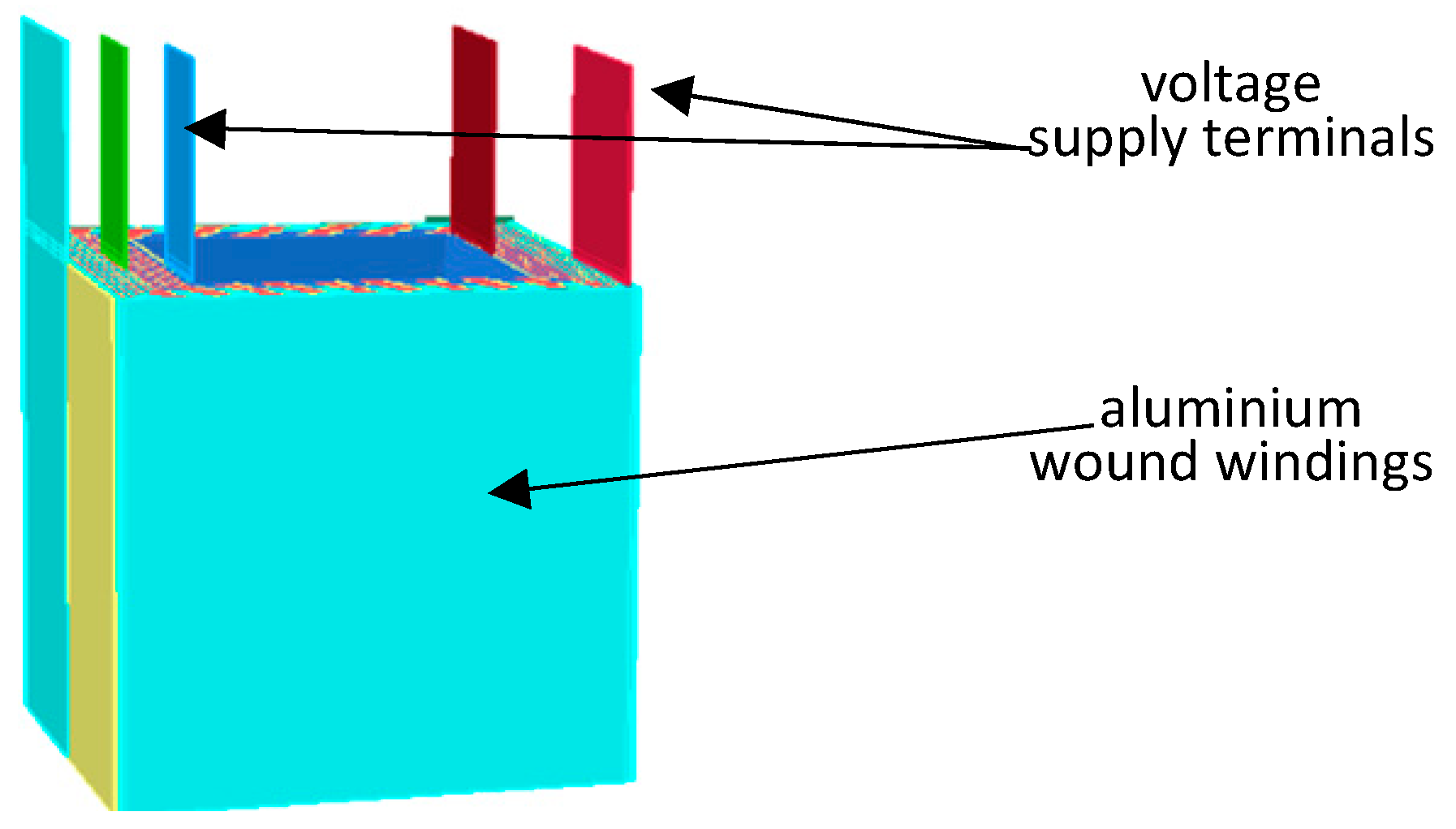
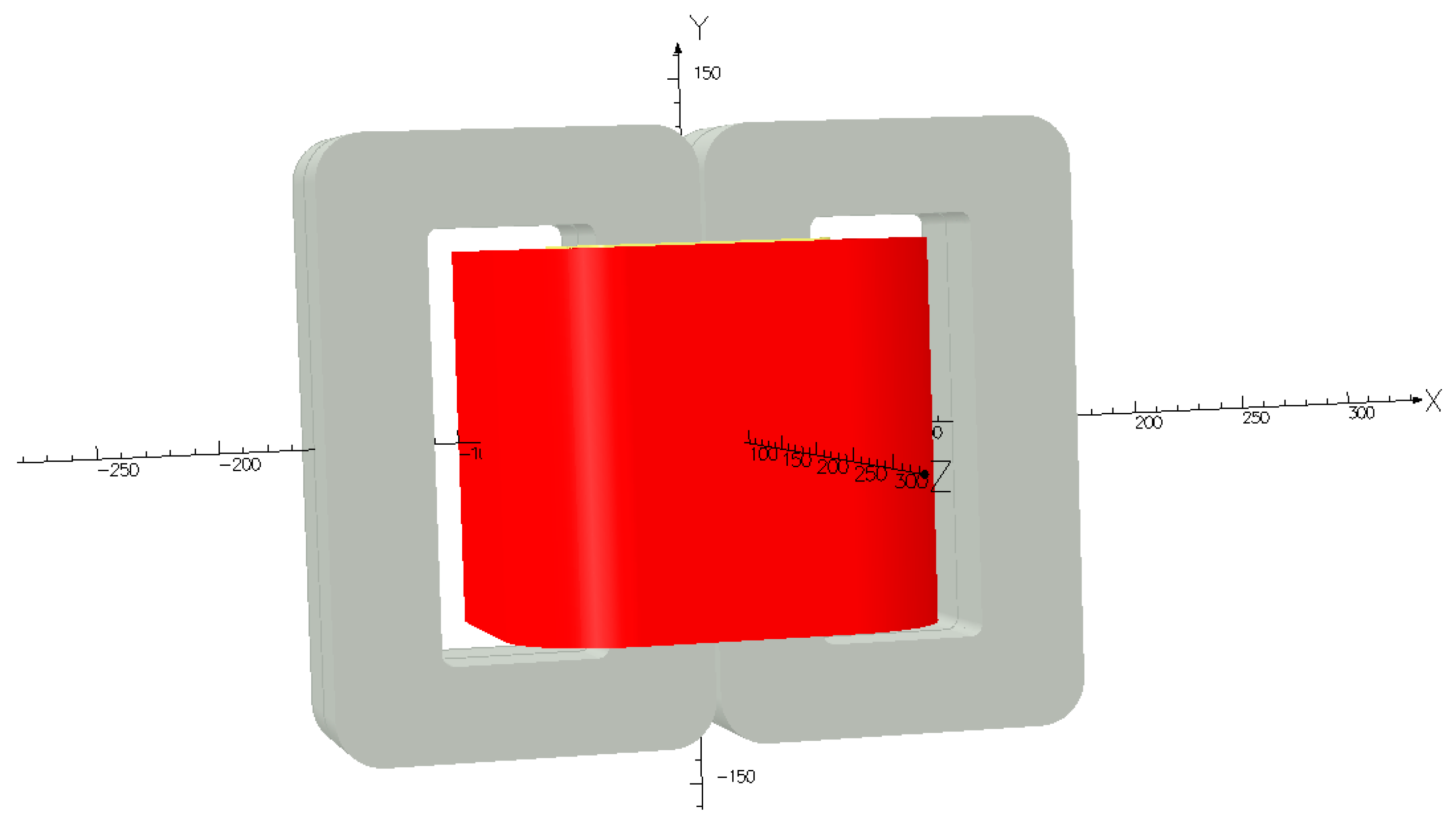
2. Construction of Medium Frequency Transformer

The core of this special transformer differs significantly from the design of power transformer cores. It consists of two parts wound from thin strips of ferromagnetic sheets and is not composed of sheets (like cores from power transformers). The GOES wound cores are made with strips wound on a steel mandrel whose shape defines the internal dimensions of the core. Core losses are acceptable thanks to using a GOES sheet with a thickness of 0.1 mm. After a thermal annealing cycle that eliminates the internal stresses, the mandrel is removed, and the wound core is cut. The cores are cut so that the windings can be put on. The cutting planes are polished with great accuracy with the range of 0.01 to 200 µm. Thus, the value possible for the air gap is from 0.02 to 400 µm. The half-cores are delivered in pairs and must be mounted together in the direction defined by the colored dots affixed by the manufacturer. The two half-cores are held together by a clamp band, which imposes a well-defined mechanical tension (70 kg for the experimental GOES transformer). Figure 1 presents the general shape of such wound cores, and Figure 2 shows the magnetization curves of both materials. Litz wire winding has a standard construction of two concentric coils, without interleaving or with interleaving turns of bundles, which needs no further explanation. The coil structure made of aluminum foil spacers is shown in Figure 3 and Figure 4.
The tested transformer has windings made of aluminum foil, a primary coil of 10 turns, and two secondary coils of 7 turns. Primary and two secondary winding are interleaving together (Figure 3 and Figure 4). The windings are made of 1 mm thick aluminum foil with 0.2 mm insulation.
The work aimed to compare the behavior of transformer windings made of thin aluminum foil or Litz windings. Two variants of the Litz winding were considered without interleaving (sequentially wound primary winding and then two secondary windings) and with interleaving of the primary and two secondary windings (Figure 5).
Calculations were also made for a transformer with the same core of grain-oriented electrical steel but with Litz windings.
Windings type Litz with technical data for frequencies up to 10 kHz were used:
  • wire diameter—0.2 mm
  • number of copper wires in a bundle—100
  • cross-sectional area of copper in a bundle—3.14 mm2
  • bundle outer diameter 2.89 mm.

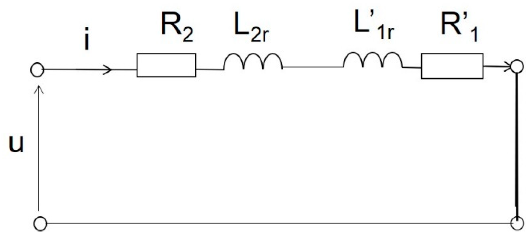
3. Mathematical Model of the Medium Frequency Transformer

The application of the aluminum foil windings forming the medium frequency transformer coils was analyzed using the 3D field method based on Maxwell’s equations. Using this method, it was possible to calculate both the currents and voltages induced in the windings of the transformer and the distribution of the magnetic field. The equation of the Helmholtz type for the harmonic electromagnetic field was used. The complex potential of the magnetic vector A (B = × A) applied in the steady state of the transformer leads to the equation of the Helmholtz-type time-harmonic equation
2 A _ μ 1 μ × × A _ j ω μ σ A _ = μ J w _
where A is the complex magnetic vector potential, B complex magnetic induction, Jw is the complex vector of primary current density, ω is the angular frequency of voltage, μ is the permeability, σ is the conductivity of materials.
At the boundary of the area, i.e., the transformer with the surrounding air, there are the following boundary conditions for the magnetic vector potential A × n = 0, which means that only the tangential part of the vector B exists on the boundary and n is a normal vector to the surface boundary.
This mathematical model (1) was used, with the nonlinear magnetic characteristics B-H of the ferromagnetic materials (nanocrystalline magnetic material and GOES) considered. As in previous research, a method was considered for power losses in laminated cores [30,31].
The commercial software OPERA 3D was used to compute field distributions. For steady state, the ELEKTRA STEADY-STATE module was used. The numbers of subdivision mesh elements for both models were determined by accuracy analyses performed by refining the mesh until the results did not change. The aluminum foil, 1 mm thick, was divided into four elements of 0.25 mm each and the height (where it is not of special importance) into 6 mm. The thickness of the insulation was 0.2 mm. As a result of the accuracy analysis, a mesh of 2,072,724 elements was adopted for all model variants with foil windings and 757,994 elements for variants with Litz windings. In the second case, it was possible to consider 1/4 of the system due to symmetries. Calculations for all variants of 3D models of transformers were made on the same principles.
Due to the possibility of performing tests, both calculations and tests were performed in the short-circuit state of the transformer (Figure 6). In this state, it is possible to measure the leakage inductance of a transformer; this inductance represents a magnetic field that does not connect both primary and secondary windings and is closed by air.
Lz = L1r + L’2r
where Lz short-circuits inductance, L2r, L’1r leakage inductance appropriately of the primary and secondary windings.
The short-circuit inductance is the sum (2) of the leakage inductances of the primary and secondary windings. The value of this inductance should be reduced to a minimum. Therefore, the research concerns this transformer parameter.

4. The Result of the Computation

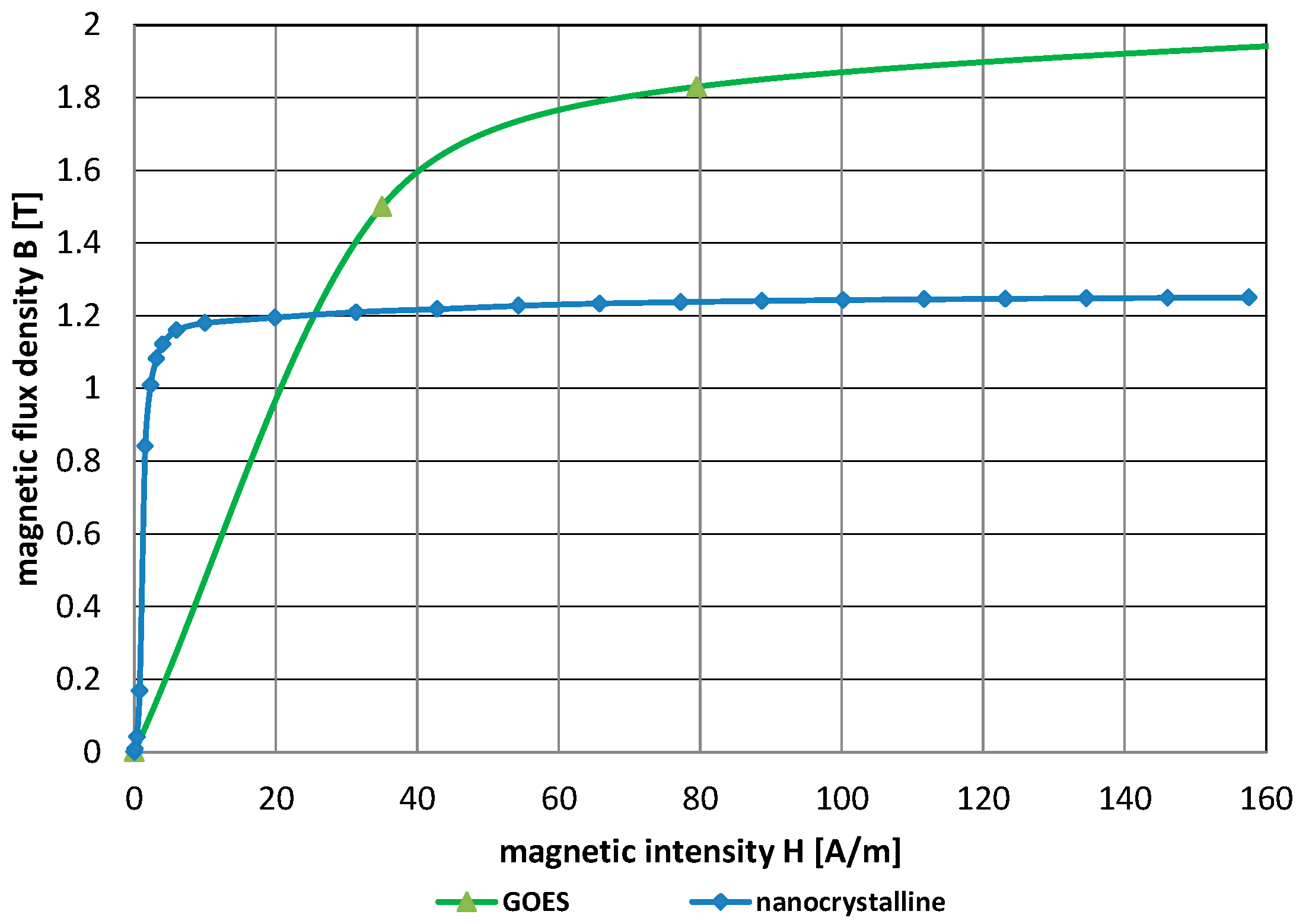
4.1. Comparison of the Materials Used for the Core

The calculations and tests present an assessment of the operation of a medium-frequency transformer with a wound core of grain-oriented electrical steel (GOES) (Figure 2) and coils wound with aluminum foil at a short circuit and frequency of 500 Hz to 6000 Hz.
The computation and tests were carried out in the same state of the transformer. The 10-turn primary coil of the tested transformer was short-circuited, while the 14-turn coil from the connection of two secondary coils of 7 turns was connected to a sinusoidal voltage of different frequencies.
Verification of previous tests using the field method confirmed that the use of nanocrystalline material cores instead of grain-oriented electrical steel (GOES) in the leakage inductance calculations gave practically the same result (Table 1). Differences in the distribution of magnetic induction result only from slight differences in the magnetic permeability of both materials (Figure 2).
During the measuring short circuit, the core is unsaturated (Figure 7). However, significant differences will occur when the transformer is loaded with high power (i.e., high current will flow) because the nanocrystalline material, despite its high magnetic permeability, saturates very quickly (Figure 2). Then, the transformer fails to fulfill its task. Therefore, grain-oriented electrical steel is not only cheaper but also a better material for cores.

4.2. Comparison of the Use of Aluminum Foil Windings or Litz Windings

To obtain the same flow in the Litz winding as in the foil windings, the area occupied by the windings in the core window must be increased (Figure 3d and Figure 5). This is because each interleaving copper wire in a bundle has its own insulation.
During the measurement short-circuit, when using foil windings, the core is very slightly saturated (Figure 7), and when using Litz windings, the core induction decreases even more (Figure 8). In contrast, leakage inductance increases because most of the magnetic flux passes through non-magnetic materials such as air and insulation (Table 2). Also, the use of interlaced Litz windings makes the induction in the core higher than non-interlaced, and the leakage inductance is slightly smaller. However, in relation to the leakage inductance, it is still an order higher (Table 2).
The short-circuit inductance, and thus the leakage inductance, are much higher in the case of Litz windings. This allows us to conclude that the interleaving windings made of aluminum foil are much more advantageous in this respect (Table 2).
In addition, it is not without significance that copper, although it has a higher conductivity of approx. 1.6 times 5600 S/mm than aluminum 3600 S/mm, the winding is much more expensive. The price of copper is about 5.4 times higher than aluminum, and the bundle Litz is more labor-intensive, which also affects its price.

4.3. Influence of Power Frequency on the Short-Circuit Reactance and Inductance of Transformers with GOES Core and Interleaved Foil Coils

The results of resistance and inductance calculations at different voltage frequencies, based on field calculations for transformer with GOES core and interleaved foil coils, are given in Table 3. The leakage reactance decreases with increasing supply frequency.
The change in resistance with increasing frequency is noticeable only at very high frequencies and results from the skin effect and the phenomenon of the proximity of conductors (Figure 9, Table 3).

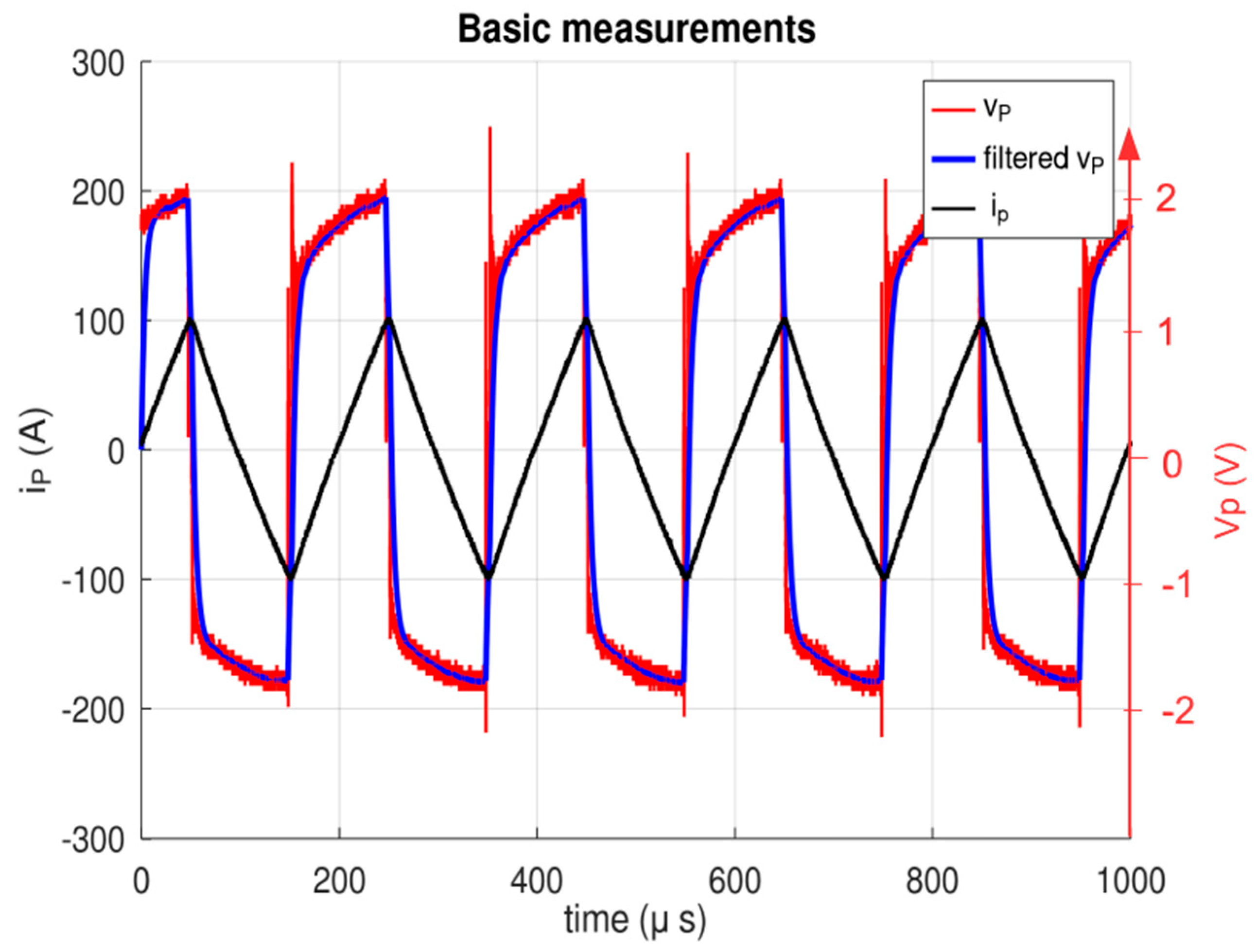
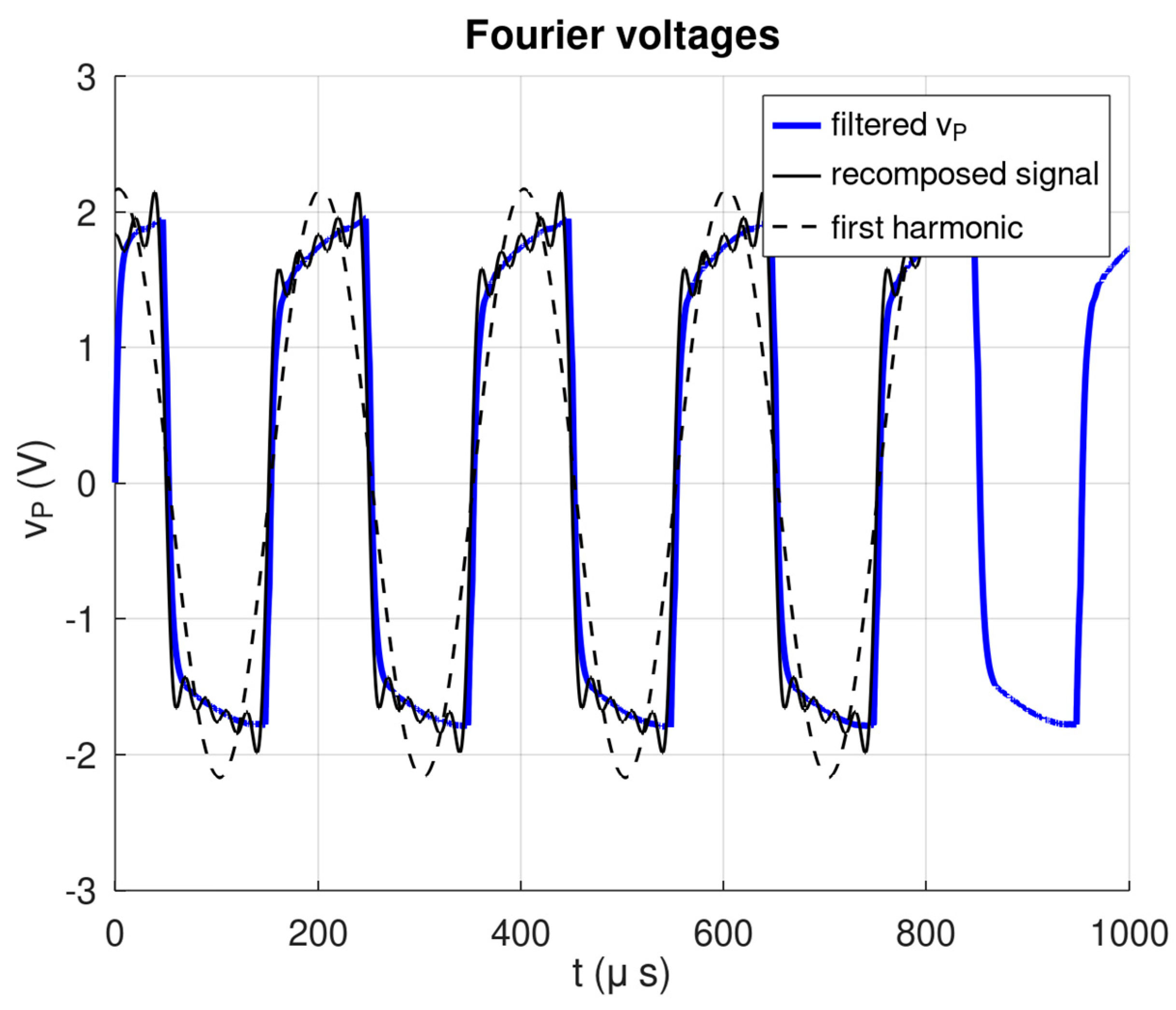
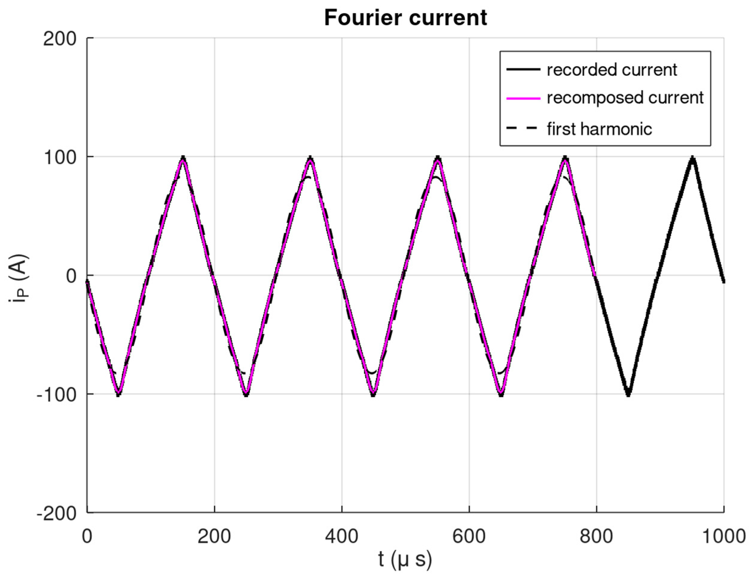
5. Prototype Description and Measurements

The 3D finite element simulation shows that the interleave aluminum foil winding structure yields a lower leakage inductance than the classical Litz one. Therefore, a prototype has been built for performing experimental verifications. Figure 10 presents this winding with 1 mm thick aluminum foils insulated by a 0.2 mm mylar sheet.
Accurate measurements are obtained when the recorded signal levels are significantly above the surrounding noise level. In the case of the short-circuit test of the transformer, the impedances are low; consequently, it is important to make measurements at high currents for obtaining voltages of the order of one volt. Considering the available current probe, the peak current was fixed to 100 A peak. At medium or high frequencies, the skin effect in the conductors is an important element that depends on frequency. Therefore, the measurements must be made with sine waves containing only one frequency. In practice, producing sinusoidal currents of such levels is very difficult. This problem has been solved using the actual voltage produced by an inverter that is not sine and decomposition in Fourier series for computing the resistance and the inductance with the first harmonic. Figure 11 presents the testing circuit; the feeding transformer provides high currents (100 A peak) with a standard inverter that operates up to 6000 Hz. It also provides galvanic insulation that connects the test point directly to the oscilloscope, accurately measuring the instantaneous voltage vp. The Tektronix A621 precision AC probe is used for the current ip. This probe has a bandwidth of 50 kHz. For each command frequency, the oscilloscope records the instantaneous values with 100,000 points on several periods and provides the corresponding data files to a computer.
The phase lag introduced by the limited bandwidth of the current probe is compensated by filtering the recorded data for the voltage: a Butterworth first-order low-pass numeric filter at 50 kHz is used for the voltage data, while the current data are used directly. This filter introduces the same phase lag on voltage as the current probe. It also eliminates the fast transients due to the classical high-frequency perturbations due to the inverter’s fast switching.
Figure 12 presents an example of the recorded and filtered signal measured at 5 kHz. The current y-scale is on the left, and the voltage is on the right. High-frequency perturbations are observed on the recorded signal v P (red curve), while the natural filtering of the current probe cleans the recorded current i P (black curve). The blue curve shows the filtered voltage, and the high-frequency perturbations are eliminated.
A Fourier series of the recorded current and the filtered voltage is computed using an integer number of periods of the signals. The equivalent resistance and inductance are calculated with the first harmonic of the filtered voltage and current. Figure 13 and Figure 14 show the recorded signal and the Fourier composition using ten harmonics. They also show the first harmonic of the voltage and od the current.

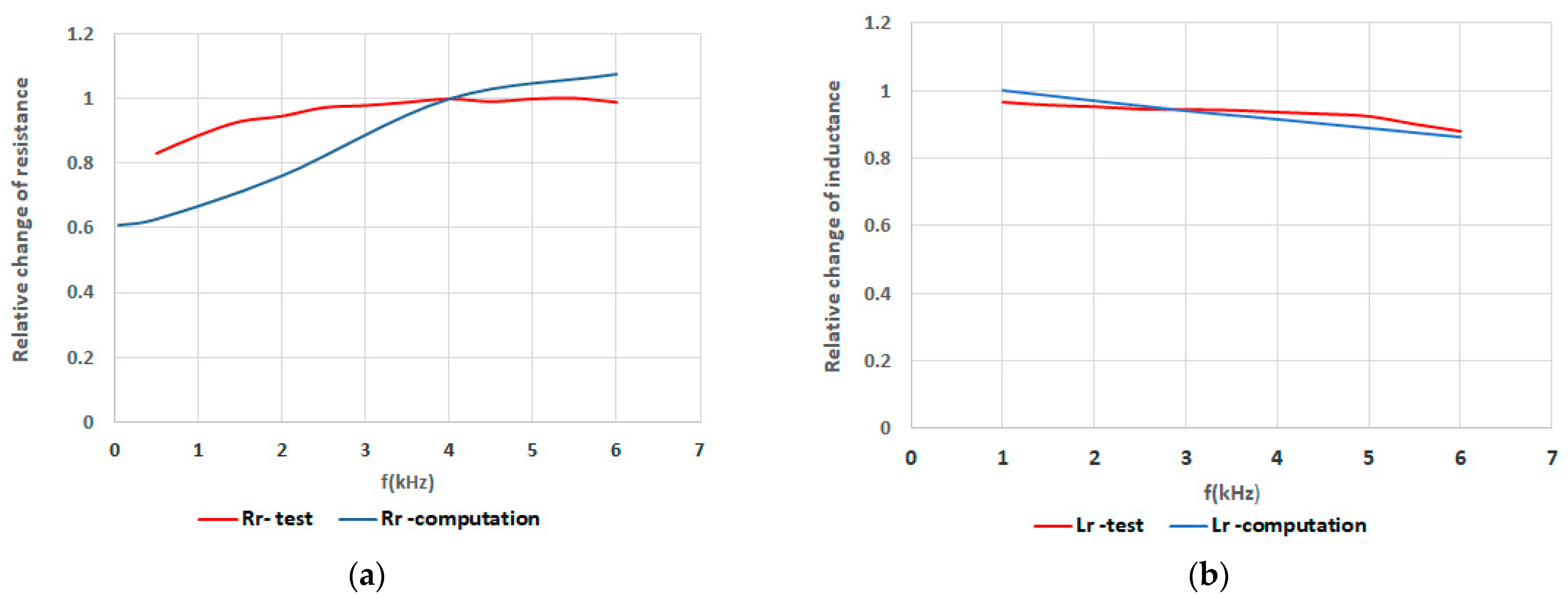
6. Comparison of Simulation and Experimental Results

Measurement errors are estimated considering that the oscilloscope (with the probes) acquires each signal with an error equal to ±1% of the channel’s full range. Therefore, the 100 A probe provides an absolute error of ±1 A on each recorded point, corresponding to a relative error of ±1.21% for the peak value of the first harmonic. The voltage is measured using a 5 V full scale; the absolute error is ±0.05 V on each recorded point, corresponding to a relative error of ±2.31% for the first harmonic peak value. The relative error on the complex impedance is estimated to be ±3.52%, supposing that the numeric process that uses the recorded files is exact.
Results of the relative change of short-circuit resistance and leakage inductance versus frequency are presented in Figure 15a,b.
The results of measurements and calculations of the short-circuit resistance and leakage induction of the transformer differ by about 17%, but the values at 3000–4000 Hz are very similar.
The differences are much more significant for leakage inductance. The greater spacing between the aluminum foils can explain the higher leakage inductance measured on the prototype. During the winding process, the mechanical stresses of the aluminum foils wound on a square mandrel cause close contact with the 0.2 mm thick insulation layer only in the corner. Therefore, the actual shape differs from the theoretical; the distances between the foils are not constant but are much more significant in the middle of each side of the square. The leakage flux is greater due to the greater distance between the foils; therefore, the leakage inductance is higher.
There are considerable differences between simulation and measurement. In the 3D model, according to the design, the insulation between the foils was 0.2 mm, i.e., along the width of the windings along the core window, the insulation cross-section of the windings is 1.2 mm × 24 = 28.8 mm, and the insulation between the turns takes 4.8 mm and the same in the perpendicular direction (Figure 3 and Figure 9).
However, in the prototype (Figure 10) in the same cross-section, it is approx. 38 mm, i.e., 38 mm ÷ 24 = 1.58 mm, and the insulation and air together give 13.98 mm. It should be added that six connection bars 32 × 5 mm are attached to the windings. Bars are connected perpendicularly on different sides and in other places of windings (Figure 10). Additional air gap dimensions due to connections can be estimated at approx. 5 mm, i.e., 18.98 mm in total. This is a significant difference. It causes a different value of the leakage inductance than assumed. The proportion of gaps between the prototype and the 3D model is about four times. Similarly, the measured value of the leakage inductance at 6000 Hz is 0.795 μH, and the calculated value is 0.19873 μH, nearly four times higher.
The above phenomenon is described in detail in the article [14] for a different type of transformer with foil windings. Of course, this is not a linear relationship.
In the case of resistance, the calculated resistance of the foil windings increases with increasing frequency due to the skin effect and proximity of foils, which is visible in Figure 9. However, the measurements on the prototype also show an almost constant value of resistance, which is related to significant air gaps and the lack of proximity effect.
The effect of frequency on changes in inductance is the same in both cases (Figure 15).
However, the measured leakage inductance remains very low (less than 1 µH), four times less than the value calculated for interlaced Litz coils. The inductance is, therefore, minimal, but it strictly depends on the spacing between successive layers of windings. In the target device, it will be necessary to use some technology to ensure the adhesion of the layers of the windings (probably gluing during winding).

7. Conclusions

For designing high-power SSTs, the MFT leakage inductance is a critical parameter.
As stated previously, the correct operation of the system requires obtaining the smallest value of the leakage inductance because the power that can be transferred through the transformer depends on it. So far, leakage inductance calculations have been based on approximate analytical formulas or 2D simulations. Unfortunately, in the 2D simulation, only a part of the windings in the transformer window is modeled, and the remaining significant portion of the winding, about 70% working in the air, is not modeled. Therefore, there are substantial differences between simulation and measurement. The second problem is the edge effect and proximity phenomena, which, apart from the skin effect, cause a considerable unevenness of the current distribution in the foil winding. As the analysis shows, the end effect (uneven current distribution at the height of the winding foil) is more important than the skin effect itself.
For this reason, only the 3D model allows us to consider all these phenomena (correct field distribution inside and outside the transformer window). For the over 2 million elements, it is practically impossible to 3D model the entire transformer under load. The control method would require a time-step solution with a sufficiently short time step, which exceeds the current calculation possibilities even when using parallel calculations. We tried to carry out such simulations in 2D, and the calculation time was very long. Therefore, the 3D harmonic variant using the complex representation of field quantities seems to be the best solution for now.
The use of 3D modeling was critical in determining the choice of winding type. This first step convinced the researchers that the chosen structure in the form of an interlaced aluminum foil winding could give good experimental results; this paved the way for the construction of a prototype. Measurements of the actual resistance and leakage inductance confirm this trend despite slightly higher leakage inductances (Figure 15), explained by the winding construction process. In addition, the experimental phase using the prototype identifies critical elements of the winding design that can be improved if lower leakage inductances are required.
Further work on the medium frequency transformer (SST) design operating at a frequency of 500 Hz to 6000 Hz will include an analysis of the interaction of the transformer with the converters and the load and, therefore, further optimization of the structure. The next step towards a more powerful SST will be a detailed study of its ability to operate at higher voltages compatible with a new generation of high-power electronic switches.

Author Contributions

Conceptualization: E.L. and D.R.; methodology: D.R. and E.L.; software: E.L.; validation: E.L. and D.R.; formal analysis: E.L.; investigation: D.R.; resources: E.L.; data curation: E.L. and D.R.; writing—original draft preparation: E.L. and D.R.; writing—review and editing: E.L.; supervision: E.L. All authors have read and agreed to the published version of the manuscript.

Funding

This research received no external funding.

Data Availability Statement

The data presented in this study are available on request from the corresponding author. Computer data is not publicly available because it is not suitable for use by other researchers.

Conflicts of Interest

The authors declare no conflict of interest.

References

  1. Ortiz, G.; Leibl, M.; Kolar, J.W.; Apeldoorn, O. Medium Frequency Transformers for Solid-State-Transformer Applications—Design and Experimental Verification. In Proceedings of the IEEE 10th International Conference on Power Electronics and Drive Systems (PEDS), Kitakyushu, Japan, 22–25 April 2013; pp. 1285–1290. [Google Scholar] [CrossRef]
  2. Chen, B.; Liang, X.; Wan, N. Design Methodology for Inductor-Integrated Litz-Wired High-Power Medium-Frequency Transformer with the Nanocrystalline Core Material for Isolated DC-Link Stage of Solid-State Transformer. IEEE Trans. Power Electron. 2020, 35, 11557–11573. [Google Scholar] [CrossRef]
  3. Hannan, M.A.; Ker, P.J.; Lipu, M.S.H.; Choi, Z.H.; Rahman, M.S.A.; Muttaqi, K.M.; Blaabjerg, F. Blaabjerg State of the Art of Solid-State Transformers: Advanced Topologies, Implementation Issues, Recent Progress and Improvements. IEEE Access 2020, 8, 19113–19132. [Google Scholar] [CrossRef]
  4. Bahmani, M.A.; Thiringer, T.; Kharezy, M. Design Methodology and Optimization of a Medium-Frequency Transformer for High-Power DC–DC Applications. IEEE Trans. Ind. Appl. 2016, 52, 4225–4233. [Google Scholar] [CrossRef]
  5. Rylko, M.; Hartnett, K.; Hayes, J.; Egan, M. Magnetic material selection for high power high frequency inductors in dc-dc converters. In Proceedings of the 2009 Twenty-Fourth Annual IEEE Applied Power Electronics Conference and Exposition, Washington, DC, USA, 15–19 February 2009; pp. 2043–2049. [Google Scholar] [CrossRef]
  6. Dujic, D.; Kieferndorf, F.; Canales, F.; Drofenik, U. Power electronic traction transformer technology. In Proceedings of the 7th International Power Electronics and Motion Control Conference, Harbin, China, 2–5 June 2012; Volume 1, pp. 636–642. [Google Scholar] [CrossRef]
  7. Bahmani, M.A.; Thiringer, T.; Ortega, H. An accurate pseudo empirical model of winding loss calculation in HF foil and round conductors in switchmode magnetics. IEEE Trans. Power Electron. 2014, 29, 4231–4246. [Google Scholar] [CrossRef]
  8. Meier, S.; Kjellqvist, T.; Norrga, S.; Nee, H.-P. Design considerations for medium-frequency power transformers in offshore wind farms. In Proceedings of the 2009 13th European Conference on Power Electronics and Applications, Barcelona, Spain, 8–10 September 2009; pp. 1–12. [Google Scholar]
  9. Villar, I. Multiphysical Characterization of Medium-Frequency Power Electronic Transformers. Ph.D. Thesis, École Polytechnique Fédérale De Lausanne, Lausanne, Switzerland, 2010. [Google Scholar] [CrossRef]
  10. Kumar, B.M.; Kumar, A.; Bhat, A.H.; Agarwal, P. Comparative study of dual active bridge isolated DC to DC converter with single phase shift and dual phase shift control techniques. In Proceedings of the 2017 Recent Developments in Control, Automation & Power Engineering (RDCAPE), Noida, India, 26–27 October 2017; pp. 453–458. [Google Scholar] [CrossRef]
  11. Ruiz-Robles, D.; Ortíz-Marín, J.; Venegas-Rebollar, V.L.; Moreno-Goytia, E.; Granados-Lieberman, D.R.; Rodríguez-Rodriguez, J. Nanocrystalline and Silicon Steel Medium-Frequency Transformers Applied to DC-DC Converters: Analysis and Experimental Comparison. Energies 2019, 12, 2062. [Google Scholar] [CrossRef]
  12. Roger, D.; Rossi, M.; Ichou, H.; Blaszkowski, J. Magnetic behavior of GOES wound cores of transformers fed by square or sine voltages. J. Magn. Magn. Mater. 2022, 564, 170032. [Google Scholar] [CrossRef]
  13. Roger, D.; Napieralska, E.; Komeza, K.; Napieralski, P. Design of High−Power Solid−State Transformers with Grain−Oriented Electrical Steel Cores. Electronics 2022, 11, 2398. [Google Scholar] [CrossRef]
  14. Diaz, G.A.; Mombello, E.E.; Venerdini, G.D.G. Calculation of Leakage Reactance in Transformers with Constructive Deformations in Low Voltage Foil Windings. IEEE Trans. Power Deliv. 2018, 33, 3205–3210. [Google Scholar] [CrossRef]
  15. Ichou, H.; Roger, D.; Rossi, M. Thermal behavior of grain-oriented electrical steel wound core solid-state transformer. COMPEL 2022, 41, 732–751. [Google Scholar] [CrossRef]
  16. Jezierski, E. Power Transformer; WNT: Warsow, Poland, 1983; pp. 1–650. ISBN 5905279053229. (In Polish) [Google Scholar]
  17. Wiszniewski, A. Instrument Transformers in the Power Industry; WNT: Warsow, Poland, 1983; pp. 1–302. ISBN 8320403707. (In Polish) [Google Scholar]
  18. Koszmider, A.; Olak, J.; Piotrowski, Z. Current Transformers; WNT: Warsow, Poland, 1985; pp. 1–283. ISBN 8320407109. (In Polish) [Google Scholar]
  19. Asghari, B.; Dinavahi, V.; Rioual, M.; Martinez, J.A.; Iravani, R. Interfacing Techniques for Electromagnetic Field and Circuit Simulation Programs IEEE Task Force on Interfacing Techniques for Simulation Tools. IEEE Trans. Power Deliv. 2009, 24, 939–950. [Google Scholar] [CrossRef]
  20. Amoiralis, E.I.; Georgilakis, P.S.; Tsili, M.A.; Kladas, A.G. Global transformer optimization method using evolutionary design and numerical field computation. IEEE Trans. Magn. 2009, 45, 1720–1723. [Google Scholar] [CrossRef]
  21. Tong, Z.; Braun, W.D.; Rivas-Davila, J. Design and Fabrication of Three-Dimensional Printed Air-Core Transformers for High-Frequency Power Applications. IEEE Trans. Power Electron. 2020, 35, 8472–8489. [Google Scholar] [CrossRef]
  22. Konrad, A.; Brudny, J.F. Virtual air gap length computation with the finite-element method. IEEE Trans. Magn. 2007, 43, 1829–1832. [Google Scholar] [CrossRef]
  23. Lesniewska, E. Applications of the Field Analysis during Design Process of Instrument Transformers. In Transformers. Analysis, Design, and Measurement; Lopez-Fernandez, X.M., Ertan, B.H., Turowski, J., Eds.; CRC Press Taylor & Francis Group: Boca Raton, FL, USA; London, UK; New York, NY, USA, 2012; pp. 349–380. [Google Scholar]
  24. Dems, M.; Komeza, K.; Kubiak, W.; Szulakowski, J. Impact of Core Sheet Cutting Method on Parameters of Induction Motors. Energies 2020, 13, 1960. [Google Scholar] [CrossRef]
  25. Lesniewska, E.; Olak, J. Analysis of the Operation of Cascade Current Transformers for Measurements of Short-Circuit Currents with a Non-Periodic Component with a Large Time Constant of Its Decay. Energies 2022, 15, 2925. [Google Scholar] [CrossRef]
  26. Lesniewska, E.; Kaczmarek, M.; Stano, E. 3D Electromagnetic Field Analysis Applied to Evaluate the Accuracy of a Voltage Transformer under Distorted Voltage. Energies 2021, 14, 136. [Google Scholar] [CrossRef]
  27. Lesniewska, E.; Olak, J. Improvement the Insulation System of Unconventional Combined Instrument Transformer Using 3D Electric Field Analysis. IEEE Trans. Power Deliv. 2018, 33, 2582–2589. [Google Scholar] [CrossRef]
  28. KING MAGNETICS Catalogue; Zhuhai King Magnetics Technology Co., Ltd.: Zhuhai, China, 2018; Available online: http://www.kingmagnetics.com/kingmagnetics_catalog.pdf (accessed on 31 July 2023).
  29. Isolectra Martin Company Catalogue. Available online: https://www.isolectra.fr/catalogue_isolectra_en (accessed on 31 July 2023).
  30. Markovic, M.; Perriard, Y. Eddy current power losses in a toroidal laminated core with rectangular cross section. In Proceedings of the 12th International Conference on Electrical Machines and Systems, Tokyo, Japan, 15–18 November 2009; pp. 1–4. [Google Scholar]
  31. Zirka, S.E.; Moroz, Y.I.; Marketos, P.H.; Moses, A.J. Evolution of the loss components in ferromagnetic laminations with induction level and frequency. J. Magn. Magn. Mater. 2008, 320, e1039–e1043. [Google Scholar] [CrossRef]
  32. Roger, D.; Napieralska, E.; Komeza, K.; Napieralski, P. Solid-state transformers of smart high-power battery charger for electric vehicles. IEEE Trans. Ind. Appl. 2023, 1–10. [Google Scholar] [CrossRef]
Figure 1. The wound core considered for both technologies (nanocrystalline material or grain-oriented electrical steel) of the considered transformer.
Energies 16 06528 g001
Figure 2. Magnetization curve of the nanocrystalline magnetic material [28] and grain-oriented electrical steel (GOES) [29].
Energies 16 06528 g002
Figure 3. Interleaved foil coils of primary and secondary windings, (a) design (b) simulation—top view (c) 3D—interleaving foil coils (d) 3D model of the medium frequency transformer, colors: primary coil-red, secondary coils-blue and aquamarine, insulation-yellow, wound core-grey.
Energies 16 06528 g003
Figure 4. 3D view of the interleaving aluminum foil winding with voltage supply terminals, colors: primary coil-red, secondary coils-blue and aquamarine, insulation-yellow, potential zero-green.
Energies 16 06528 g004
Figure 5. 3D model of the medium frequency transformer with the Litz winding (dimensions in millimeters).
Energies 16 06528 g005
Figure 6. The equivalent circuit of a short-circuited transformer seen from the secondary winding.
Energies 16 06528 g006
Figure 7. Distributions of magnetic induction (mT) in the cores of transformers with interleaved foil coils in the short-circuit state at 6000 Hz power supply, (a) core made of GOES (b) core made of nanocrystalline material.
Energies 16 06528 g007
Figure 8. Distributions of magnetic induction (μT) in the cores of transformers with cores made of GOES in the short-circuit state at 6000 Hz power supply, (a) Litz windings without interleaving (sequentially wound primary winding and then two secondary windings), (b) Litz windings with interleaving of the primary and two secondary windings.
Energies 16 06528 g008
Figure 9. Distributions of current density (A/mm2) in the cross-section of foil windings in a transformer with a GOES core and interleaved foil coils at a supply frequency of (a) 6000 Hz and (b) 3000 Hz.
Energies 16 06528 g009
Figure 10. (a) The picture taken from above the interleave foil windings and (b) view of the prototype with its GOES wound core.
Energies 16 06528 g010
Figure 11. Short-circuit tests, measurement circuit [32].
Energies 16 06528 g011
Figure 12. Example of instantaneous voltage and current.
Energies 16 06528 g012
Figure 13. Filtered voltage, Fourier recomposed voltage with ten harmonics and the first one.
Energies 16 06528 g013
Figure 14. Recorded voltage, Fourier recomposed signal and first harmonic.
Energies 16 06528 g014
Figure 15. Relative change of short-circuit (a) resistance and (b) leakage inductance versus frequency.
Energies 16 06528 g015
Table 1. The short-circuit inductance of transformers with interleaved foil coils.
FrequencyGOESNanocrystalline Material
6000 Hz0.1987 μH0.1965 μH
4000 Hz0.2308 μH0.2080 μH
3000 Hz0.2739 μH0.2468 μH
2000 Hz0.2732 μH0.2459 μH
500 Hz0.3101 μH0.2804 μH
Table 2. The short-circuit inductance of transformers GOES core with Litz windings and foil windings at 6000 Hz.
Litz WindingsFoil Windings
Without InterleavingWith InterleavingWith Interleaving
9.1056 μH3.8245 μH0.1987 μH
Table 3. The short-circuit inductance and reactance of transformers with GOES core and interleaved foil coils.
Frequency500 Hz2000 Hz3000 Hz4000 Hz6000 Hz8000 Hz10,000 Hz
Inductance0.31015 μH0.27323 μH0.27395 μH0.23082 μH0.19873 μH0.17670 μH0.16176 μH
Reactance3.4603 mΩ4.1988 mΩ4.8324 mΩ5.5133 mΩ5.9340 mΩ7.4873 mΩ8.0932 mΩ
Disclaimer/Publisher’s Note: The statements, opinions and data contained in all publications are solely those of the individual author(s) and contributor(s) and not of MDPI and/or the editor(s). MDPI and/or the editor(s) disclaim responsibility for any injury to people or property resulting from any ideas, methods, instructions or products referred to in the content.

