Article

Field Test Method and Equivalence Analysis of Delay Characteristics of DC Electronic Current Transformer

1
Electric Power Research Institute of Yunnan Power Grid Co., Ltd., Kunming 650200, China
2
Faculty of Electric Power Engineering, Kunming University of Science and Technology, Kunming 650500, China
3
Measurement Verification Department of Measurement Center of Yunnan Power Grid Co., Ltd., Kunming 650200, China
*
Author to whom correspondence should be addressed.
Energies 2023, 16(15), 5727; https://doi.org/10.3390/en16155727
Submission received: 2 May 2023 / Revised: 13 June 2023 / Accepted: 28 June 2023 / Published: 31 July 2023

Abstract

:
DC electronic current transformer is the data source of the system control and protection device, so its measurement delay has always been concerned. In this paper, the DC current transformer is modelled equivalently and the key factors affecting the delay of shunt and the remote module are analyzed. A field test method for the delay characteristics of the DC electronic current transformer is proposed. Moreover, a complex multi-state large current generator and integrated test system are developed. On the basis of the IEC 60044-8 standard transmission protocol, the accuracy of standard signal acquisition with the shunt is better than 0.2%. The maximum output current of the established testing system is 600 A. Based on the field test in an actual HVDC project, transient step and various frequency signal components are applied for analyzing.

1. Introduction

Ultra (extra) high-voltage DC transmission (HVDC) is widely used in large-capacity and long-distance transmission projects, which has incomparable advantages in terms of controllability and flexibility. However, it also increases the risk of system resonance, especially in the asynchronous operation mode of the power grid. For example, the impact of harmonics on the safe and stable operation of the power grid is more prominent because harmonic resonance has a direct impact on transformer tap changers, stabilization devices, and other secondary equipment. In serious cases, it can even affect the isolation of the main equipment [1]. As a key device for the measurement data of the control and protective system, the measurement delay of DC current transformers is prone to the risk of broadband oscillations. Therefore, it is of great importance to understand the measurement delay of the direct current electronic current transformer to develop on-site testing systems for delay characteristics. It is crucial for adjusting control system circuit parameters, conducting rapid wideband oscillation suppression, and achieving precise measurements.
Nowadays, the widely used DC electronic current transformer is based on the shunt-sensing principle, which covers a whole data transmission chain, including primary sensing conversion, analog voltage acquisition, digital signal conversion, fiber optic transmission, merging unit (MU) processing, telegram transmission, control, and protection device reception processing [2]. The rated secondary signal of the DC electronic current transformer is a voltage signal of several tens of millivolts with digital information, which is different from the traditional instrumentation transformer with analog output.
In order to model and calibrate DC current transformers, the reference [3] proposes a laboratory calibration method for DC current transformers and conducts research on the uncertainty assessment of calibration results. Reference [4] presents a field calibration method for DCCT. This method synchronizes the DC current transformer field calibration by using GPS to measure the readings of the digital multimeter on the standard source side and the calibrated transformer’s two ends. The measurement principle of this method and system is analyzed. If the calibrated DC current transformer has an analog output, GPS synchronization is used, and the data from the two-end digital multimeters are obtained. If the calibrated DC current transformer has a digital output, communication radios are used for synchronization. However, employing method, it is challenging to achieve on-site synchronization verification of the delay characteristics and transient characteristics of direct current electronic current transformers. This is because it relies on the stability of the current source and may not be suitable for achieving precise synchronization in the field. Reference [5] describes the design and setup of the new AC current transformer (CT) calibration system, which uses enhanced, actively compensated current comparators (CCs) for improving measurement accuracy. Reference [6] proposes a 3D magnetic-field model to analyze the impact of the magnetic sensor circular array position on current measurements, which successfully maintains accuracy class 1.0 under various position deviations in balanced or unbalanced three-phase power delivery systems. References [7,8] study from the perspective of shunt to improve measurement accuracy. Reference [9] proposes that the disparity in practical environmental conditions, which influences the proximity electric field, is a significant reason for active electronic voltage transformers exhibiting excessive errors at substation sites. The principles of selecting materials for capacitive voltage dividers and rationalization proposals for error calibration are given. In paper [10], a new method for performing power current measurement is proposed; this method involves the use of Hall sensors without iron cores, which greatly reduces the interference of environment on measurement. Currently, there is a lack of in-depth research on the delay characteristics of direct current electronic current transformers (DCCT). Due to limitations in testing methods and technical conditions, on-site calibration of delay testing under simulated operating conditions has not been effectively conducted. In particular, there is a lack of in-depth research and on-site test data analysis on the calibration of delay under different signal excitations. In DC systems, various signal waveforms occasionally appear, especially in wideband signal detection, relay protection, and control parameter adjustments, which requires more accurate measurement of the delay of direct current electronic current transformers.
The installation position of DC electronic current transformers in converter stations is dozens of meters high above the ground, so the disassembly and reconnection of high-voltage joints pose difficulties [11,12,13,14]. In order to complete the field test, this study first establishes an equivalent model for the delay characteristics of DC current transformers. Then, the impact of shunts and low-pass filters on the delay is analyzed. In the actual converter station, a field test method to measure the delay characteristics of direct current electronic current transformers is proposed. Furthermore, a complex polymorphic high-current generator and a related integrated testing system for delay characteristics are developed. Based on these devices, a field equivalent test circuit topology is constructed. Finally, the testing results in practical engineering are analyzed and compared.

2. Delay Analysis and Test Method Research

2.1. Causes of Delay

The DC electronic current transformer contains a remote module and an analog-to-digital conversion unit; hence, its structure can be simplified into three parts as shown in Figure 1. In Figure 1, Rk is the resistance of the shunt; Lk is the distribution inductance of the shunt; Is the primary current flowing through the shunt; Up is the secondary disconnect output voltage of the shunt.
The voltage and current in Figure 1 adhere to the following equation:
U P = j ω L k + R k I s .
Lk in Equation (1) has an impact on the transient characteristics of the shunt, not only on the phase shift of the transmitted high frequency signal but also on the rising edge of the step signal waveform. The shunt can have good transient response characteristics if Lk is reduced as much as possible. In addition, the low-pass filter in Figure 1 is generally composed of passive components. The filters commonly used in engineering are Bessel, Chebyshev, and Butterworth types, which present different transfer functions, resulting in different frequency delay characteristics.
The shunt and the low-pass filter together constitute the physical delay time part of the DC electronic current transformer. However, the delay time of the remote module after the AD acquisition is not related to input signal but to its sampling rate, processing method, and other factors, which can be called the rated delay time. The purpose of this paper is to accurately measure and calibrate the delay time of the DC electronic current transformer in actual operating conditions.

2.2. Field Equivalent Test Method for Delay Characteristics

Generally, the operating signals acting on the DC electronic transformer can be divided into two categories: steady state and transients. The steady-state signal is composed of DC component and high-frequency AC harmonics. The transient signal is the sudden change in electrical quantity after a fault or disturbance in the DC system. As a result, the delay characteristics field test circuit topology is designed as shown in Figure 2. It is mainly composed of current source, test object (DC electronic type current transformer), standard load (high precision resistor Rb), circuit control, and test system, etc.
The current source in Figure 2 can output many types of complex typical current waveforms. In Figure 2, Rd and Ld are the equivalent resistance and inductance of the test circuit, respectively; ub is achieved by the high-precision resistor Rb; and us is the digital telegram signal output from the DC electronic current transformer under test. Moreover, the test system needs to synchronize the acquisition of two signals from the standard load and the test object to accurately quantify the delay.

3. Delay Characteristic Test System

3.1. Test System Design and Its Operating Mechanism

The core problem of field test is how to simulate the complex polymorphic signal waveforms in the actual operating conditions with a small engineering cost in the converter station. Thus, the main technical details are determined as follows:
(1)
The step current signal is more or equal to 300 A (considered at 10% of the rated current of 3000 A) [15]; the rise time is less than 50 μs (one fifth of the step rise time of the DC transformer); and the duration is more or equal to 10 ms;
(2)
The high-band steady frequency current amplitude is adjustable; the output maximum value is 300 A; and the frequency range covers at least 50–1200 Hz;
(3)
It can output high-band frequency current with the DC component;
(4)
The steady-state accuracy, frequency response, and transient step response characteristics must be tested;
(5)
The digital interface of the delay testing system needs to comply with the transmission protocol in IEC 60044-8 standard;
(6)
The testing system is small in size and easy to install at the site;
(7)
The testing system complies with the international standard IEC 61869-14-2018.
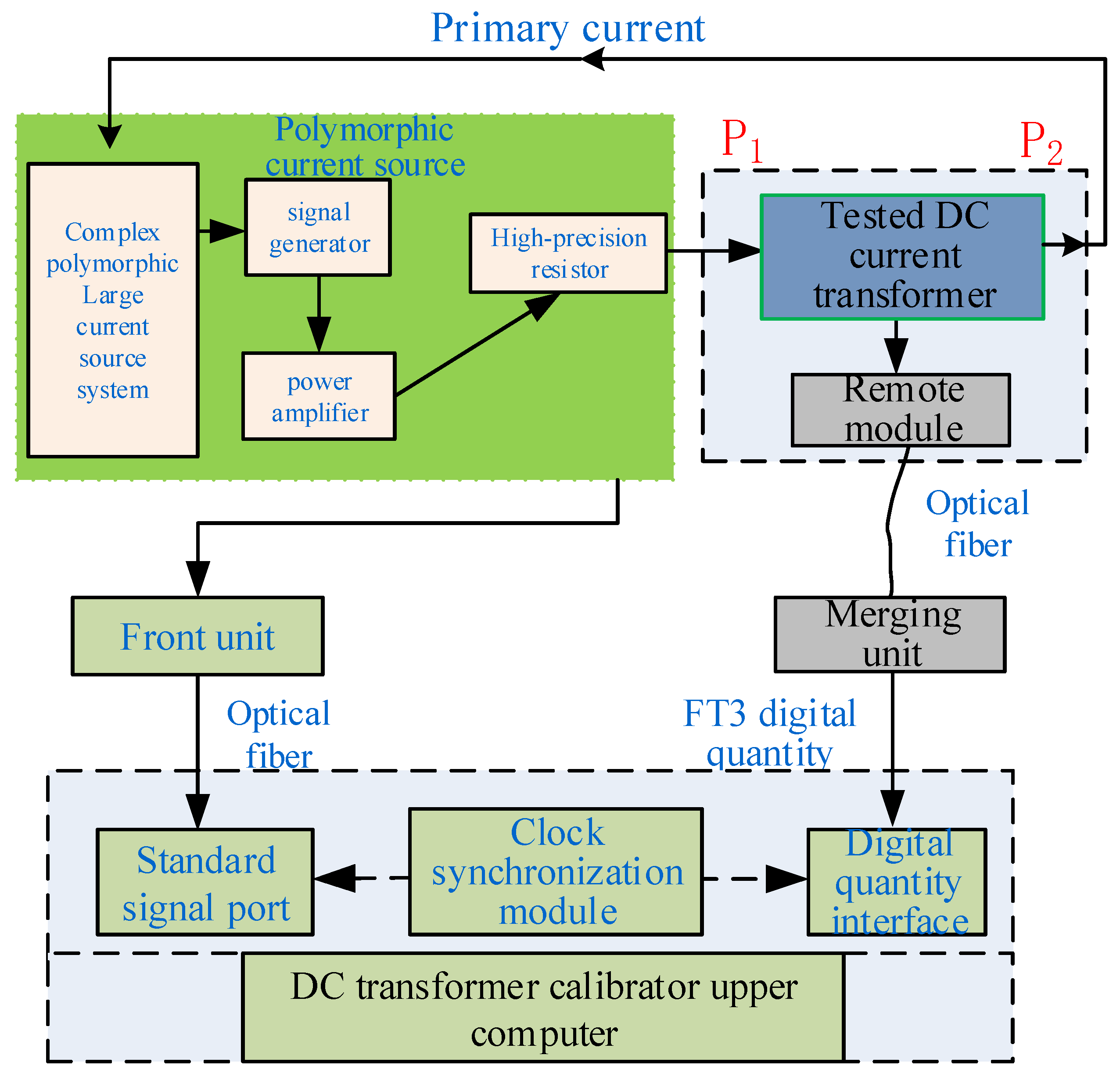
Based on the above and the actual situation in the field, the complex multi-state current signal delay test system is established as shown in Figure 3. First, the current waveform required for the test is configured in the complex multi-state high-current source system to form a series of discrete sampling points as digital signals. Second, the signal generator converts the digital signal into an analog voltage and outputs the current through the power amplifier. Third, the P1 and P2 terminal of the high-precision resistor and the subject, in turn, receive the current. Driven by the synchronous clock, the calibrator receives the standard signal collected by the front unit and the FT3 digital signal output of the test product through two optical fibers. Finally, the calibrator completes the calculation of the delay.
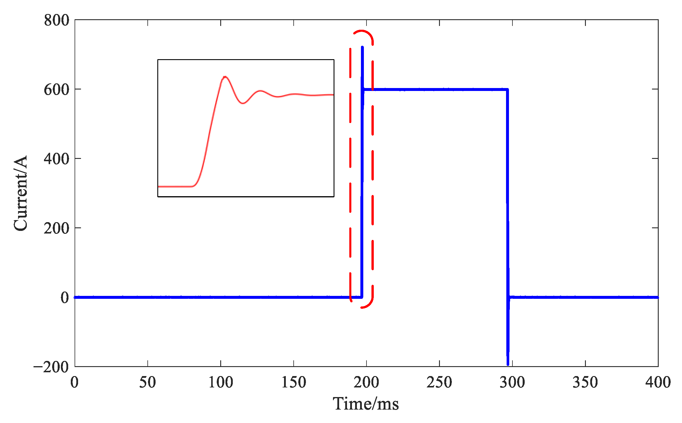
A large capacity signal generator is home-made for testing the DC electronic current transformer. The output high-band frequency current of the complex high-current power supply is 600 A maximum; the frequency band covers 50 Hz~1.2 kHz; the output frequency accuracy is better than 0.01 Hz; the step signal rising time is less than 30 μs; and the steady step can last 100 ms. The sampling frequency is designed to be 500 kHz to meet the complex multi-state current signal sampling requirements. The measurement error of the calibrator does not exceed 5 μs. To verify the adaptability of the complex multi-state high current source and calibration system, the multi-state current signal source system generates step currents which are collected by the DC transformer calibrator. Figure 4 shows the current waveform at a step amplitude of 600 A with step width of 100 ms.

3.2. Key Parameters of Delay Characteristics

(1)
Calculation method of delay of steady-state signals
The test current source outputs single frequency or DC component Idc with a high-band frequency component Iac, equivalent to the composition of the composite current source acting on the actual project. The expression is as follows:
i t = I d c + n = 1 24 I a c sin ( n ω t + φ n ) .
In this paper, the 50 Hz component, which is the power frequency in China, is applied as the fundamental frequency.
The essence of the delay calculation of the steady-state signal is to accurately calculate the phase error. In this test, the transformer calibrator is triggered by a synchronous clock with an error of less than 0.5 μs. The front unit of the standard voltage signal for high-precision acquisition extracts the phase φ1 of the standard signal as the moment of appearance of the steady-state signal on the primary side of the DC electronic current transformer. The digital output (FT3 message) of the DC electronic current transformer under test is received in real time with the same synchronous clock. Then, the phase φ2 of the measured transformer signal is extracted when the digital sampling value corresponds to the analog input. Assuming the current frequency is f, the absolute delay td is calculated by converting the phase error as follows:
t d = ( φ 2 φ 1 ) / 2 π f .
(2)
Calculation of delay of transient step signal
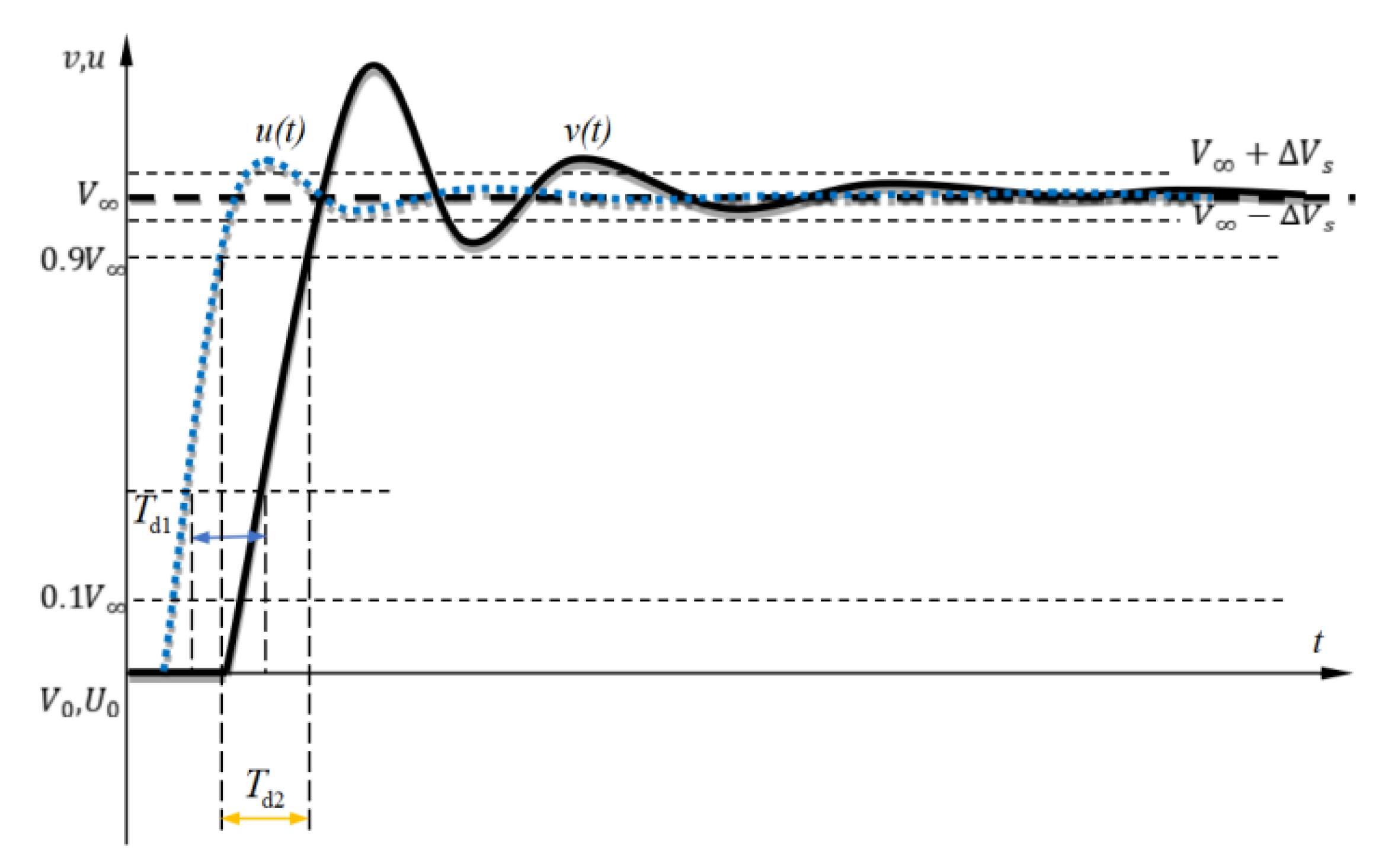
Figure 5 gives the extraction process of the delay of transient step signal. u(t) is the input step signal (standard acquisition signal); U0 is the initial value of the input variable; V(t) is the output signal of DC electronic current transformer; V0 is the initial value of the output variable before the step is applied; V is the steady-state value of the output variable after the step is applied; ΔVs is usually 5% of V; and Td1 and Td2 are the delay times at different parts of step signal, respectively.
The transient delay Td of DC electronic current transformer is defined as
T d = t b c t b z ,
where tbc and tbz are the moments when the tested DC electronic current transformer and the standard reach a certain value, respectively. First, the steady-state value, V0, before the step and the steady-state value, V, after the step are applied. Second, the moment corresponding to 10% or 90% of the variable reaching V is measured. Finally, the absolute delay of the DC current transformer is obtained.

4. Hardware Experiment

4.1. Field Test System Establishment

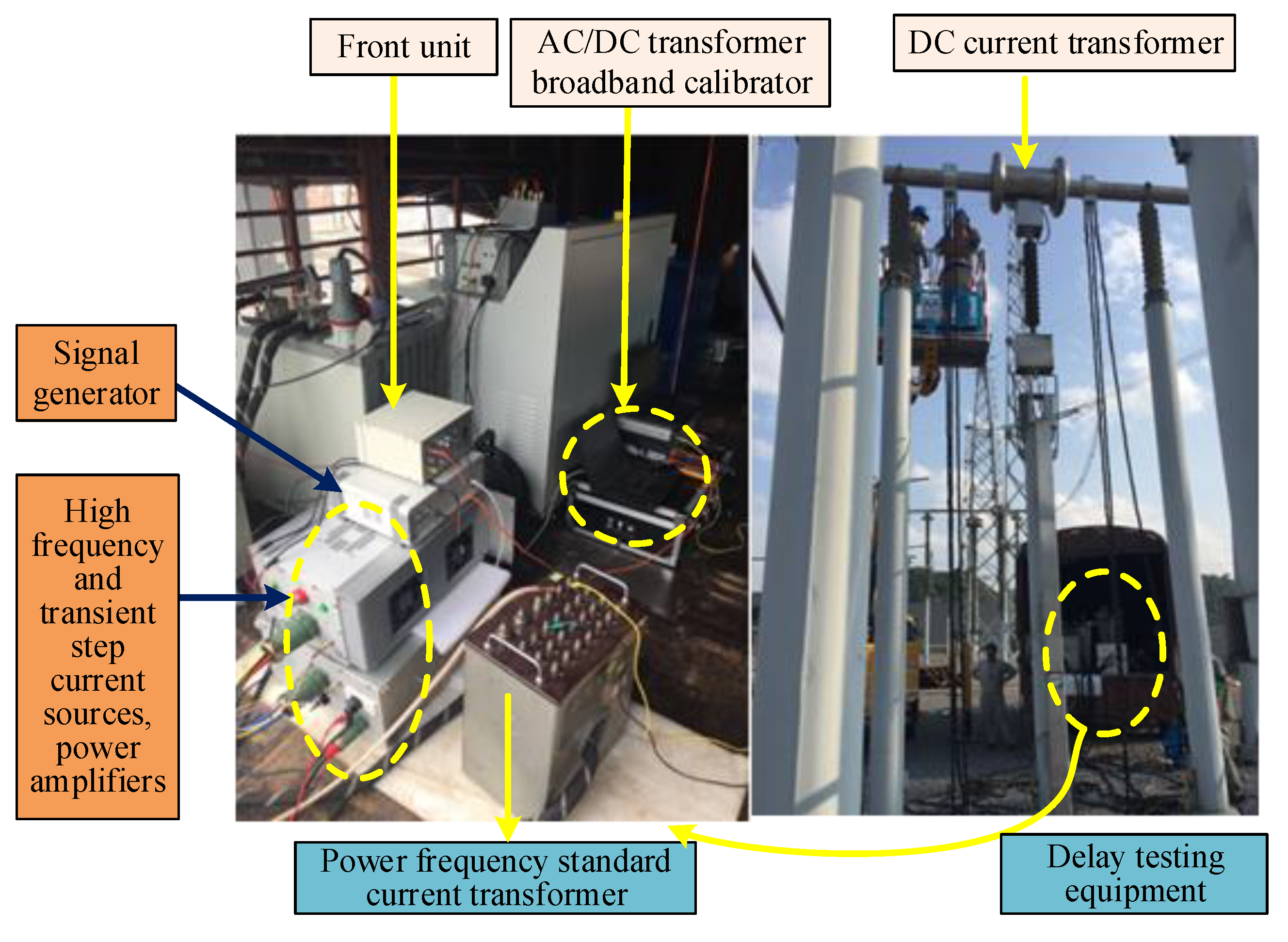
According to the requirements of GB/T 26216.1, IEC 61869, and other related standards, the field test system of the DC electronic transformer delay characteristics [6,7,8,9,10] is built as shown in Figure 6.
This equipment is designed to obtain a greater primary current output with small impedance. In addition, this equipment has to be transported over a long distance of about 400 km, mostly on mountainous road, from the storage location to the convertor station. To ensure the accuracy and credibility of the field test, this equipment is tested in the field again, which verifies its effectiveness and accuracy.
The rated primary current of the DC current transformer under test is 3000 A with 10 kHz sampling rate output. First, the delay test under 50 Hz with the accuracy level of 0.01 S of 600 A current is carried out to the DC electronic current transformer and the load. The delay of 483 μs and 486 μs are calculated in two independent tests.

4.2. Field Test of Delay Time under the Action of Steady-State AC Signal

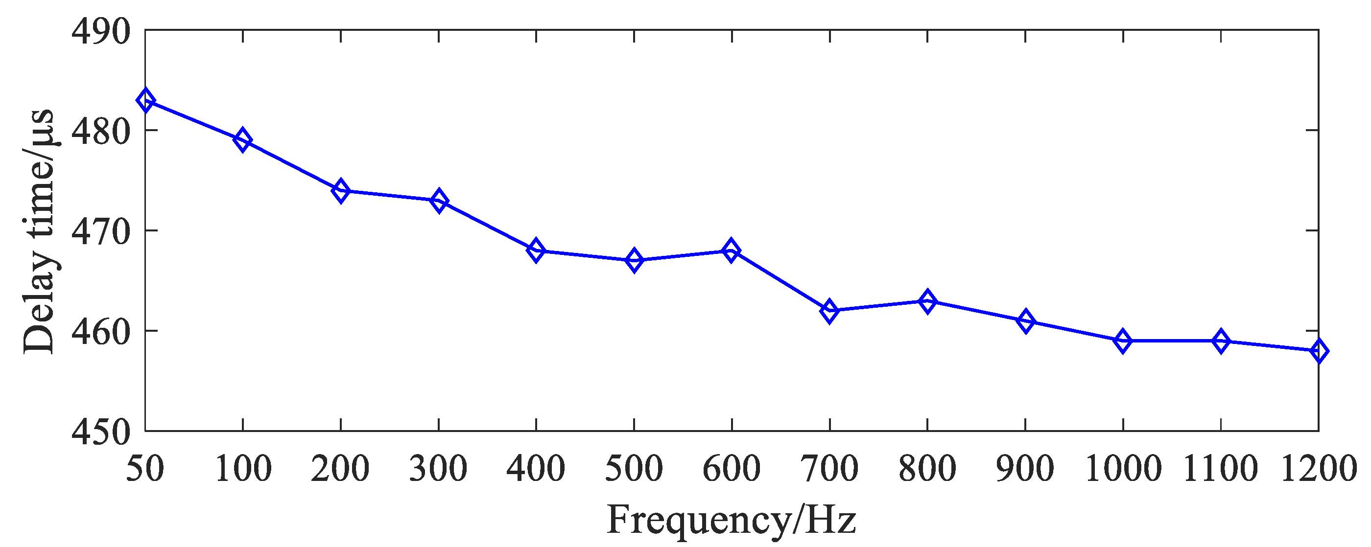
During the experiment, sinusoidal current signals from 50 Hz to 1200 Hz are sequentially applied to the DC current transformer. The calibration of the testing system is triggered and controlled by a high-precision synchronous clock. Figure 7 shows the variation of delays of different frequency components.
In Figure 8, it can be seen that the delay is gradually decreasing as the input current frequency increases, the value of which decreases from 483 μs to nearly 455 μs. In order to survey the influence of current amplitude, the current amplitude of 600 A, 410 A, and 365 A is applied on the primary side of the transformer, but the equivalent current does not have any significant effect on the delay.
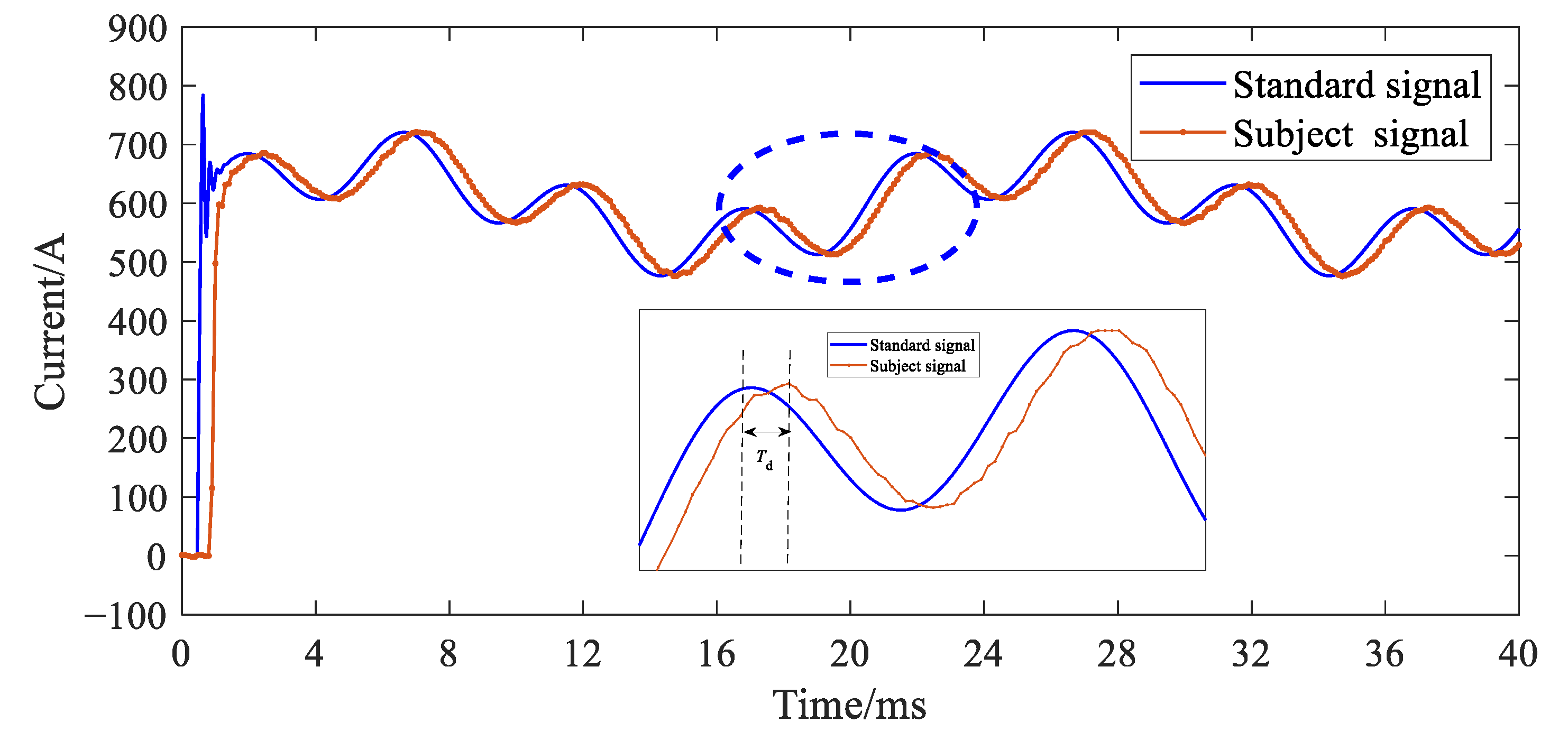
In the case of HVDC system fault, AC components are able to transmit to HVDC transmission lines, which can induce large AC components superimposing DC component. Therefore, the waveform applied to the DC electronic current transformer in fault is not a single AC or DC but a composite current waveform. To be closer to the actual operating conditions in the field, waveforms with 600 A of DC, 50 A of 50 Hz, and 40 A of 200 Hz AC components are applied to the DC electronic current transformer. In Figure 8, the waveforms from the primary side and the secondary side are illustrated, and the calculated delay is 481 μs.

4.3. Field Test of Transient Step Signal

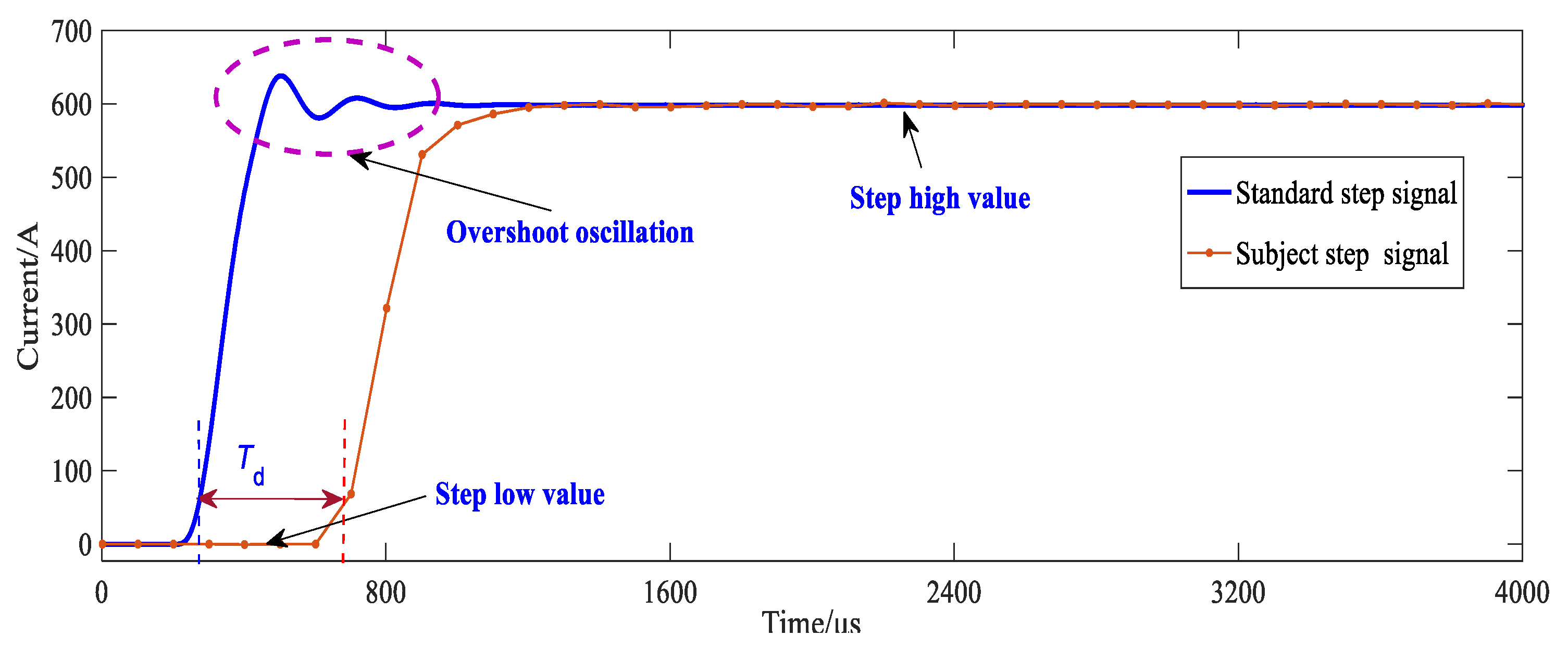
The field test result of the transient step signal on the DC electronic current transformer is shown in Figure 9.
The transient delay of the DC electronic current transformer is 415 μs at the start of rising time (the moment corresponding to 10% of step current amplitude) and 490 μs at the end of rising time (the moment corresponding to 90% of step current amplitude). There is 75 μs difference in step test, which may affect the low-pass filter by cutting off some high-frequency components.

4.4. Equivalent Analysis

This effectively analyzes the characteristic waveforms under different input to demonstrate the delay characteristics of DC electronic current transformers. These waveforms are applied to the tested DC electronic current transformers for conducting delay testing and calibration. It is necessary to ensure that the characteristic waveforms generated by the current source include single-frequency signals, DC overlaid with high-band frequency components, transient step signals, and other complex waveforms. Therefore, some requirements, e.g., 0~1500 Hz and 0~600 A current output, are imposed on the performance of the current source.

5. Conclusions

In this paper, the effects of shunt and low-pass filter on delay characteristics of DC electronic current transformers are studied. Furthermore, a field equivalent test method for the delay characteristics of DC electronic current transformers is established. Specific conclusions are as follows.
A complex multi-state high-current generation device and an integrated test system are developed, which support the IEC 60044-8 standard transmission protocol. It has a maximum output current of 600 A, with a measurement accuracy better than 0.01 Hz. Then, by simulating various signals to DC electronic current transformers, the accurate measurement and calibration of absolute delay are realized. Based on measurement results, the different frequency components are transmitted with various time delays via the transmitting of the DC electronic current transformer, which may result in the maloperation of the control system. Furthermore, the step response also reflects a nearly constant time delay of the DC electronic current transformer, even though the sampling rate of digital output of DC electronic current transformer is lower than the primary side.

Author Contributions

Conceptualization, M.Z.; formal analysis, H.T.; resources, Z.H.; methodology, Y.L.; software, B.T.; validation, Q.Z. and H.S.; investigation, Y.D. and F.Z.; project administration, P.C. All authors have read and agreed to the published version of the manuscript.

Funding

This work is supported by the Science and technology project of Yunnan Power Grid Co., Ltd. (No.YNKJXM20220161), and the Yunnan technological innovation talent training object project (No.202205AD160005).

Data Availability Statement

Data are unavailable due to privacy.

Conflicts of Interest

The authors declare no conflict of interest.

References

  1. Yao, Z.; Wu, J.; Guo, X.; Zhang, C. Analysis and Suppression Control of High Frequency Resonance for MMC-HVDC System. IEEE Trans. Power Electron. 2017, 32, 3437–3452. [Google Scholar]
  2. GB/T 26216.1-2010; DC Current Measuring Device for HVDC Transmission System—Part 1: Electronic DC Current Measuring Device. General Administration of Quality Supervision, Inspection and Quarantine of the People’s Republic of China, Standardization Administration of China; Standards Press of China: Beijing, China, 2011.
  3. Callegaro, L.; Cassiago, C.; Gasparotto, E. On the calibration of direct-current current transformers (DCCT). IEEE Trans. Instrum. Meas. 2015, 64, 723–727. [Google Scholar] [CrossRef] [Green Version]
  4. Li, Q.; Li, H.; Zhou, Y.; Li, D.; Hu, H.; Zhan, S. On-site calibration technology for direct current transformers (DCCT) in ±800 kV DC transmission system converter stations. High Volt. Eng. 2011, 37, 3053–3058. [Google Scholar]
  5. Mohns, E.; Roeissle, G.; Fricke, S.; Pauling, F. An AC Current Transformer Standard Measuring System for Power Frequencies. IEEE Trans. Instrum. Meas. 2017, 66, 1433–1440. [Google Scholar] [CrossRef]
  6. Ma, X.; Guo, Y.; Chen, X.; Xiang, Y.; Chen, K.-L. Impact of Coreless Current Transformer Position on Current Measurement. IEEE Trans. Instrum. Meas. 2019, 68, 3801–3809. [Google Scholar] [CrossRef]
  7. Zhang, J.; Pan, X.; Liu, W.; Gu, Y.; Wang, B.; Zhang, D. Determination of Equivalent Inductance of Current Shunts at Frequency Up to 200 kHz. IEEE Trans. Instrum. Meas. 2013, 62, 1664–1668. [Google Scholar] [CrossRef]
  8. Pan, X.L.; Zhang, J.T.; Shao, H.M.; Liu, W.F.; Gu, Y.; Ma, X.F.; Wang, B.; Lu, Z.L.; Zhang, D.S. Measurement of the Phase Angle Errors of High Current Shunts at Frequencies up to 100 kHz. IEEE Trans. Instrum. Meas. 2013, 62, 1652–1657. [Google Scholar] [CrossRef]
  9. Wu, W.; Xu, Y.; Xiao, X.; Hu, H. Research on Proximity Effect in Measuring Error of Active Electronic Voltage Transformers. IEEE Trans. Instrum. Meas. 2016, 65, 78–87. [Google Scholar] [CrossRef]
  10. Chen, K.-L.; Chen, N. A New Method for Power Current Measurement Using a Coreless Hall Effect Current Transformer. IEEE Trans. Instrum. Meas. 2011, 60, 158–169. [Google Scholar] [CrossRef]
  11. Jiang, J.; Zhao, M.; Zhang, C.; Chen, M.; Liu, H.; Albarracín, R. Partial Discharge Analysis in High-Frequency Transformer Based on High-Frequency Current Transducer. Energies 2018, 11, 1997. [Google Scholar] [CrossRef] [Green Version]
  12. Chen, K.-L.; Wan, R.-S.; Guo, Y.; Chen, N.; Lee, W.-J. A Redundancy Mechanism Design for Hall-Based Electronic Current Transformers. Energies 2017, 10, 312. [Google Scholar] [CrossRef] [Green Version]
  13. Kaczmarek, M.; Szczęsny, A.; Stano, E. Operation of the Electronic Current Transformer for Transformation of Distorted Current Higher Harmonics. Energies 2022, 15, 4368. [Google Scholar] [CrossRef]
  14. Wang, D.; Liu, C. Combination Optimization Configuration Method of Capacitance and Resistance Devices for Suppressing DC Bias in Transformers. Energies 2019, 12, 1813. [Google Scholar] [CrossRef] [Green Version]
  15. GB/T 20840.14-2022; Instrument Transformers—Part 14: Additional Requirements for Current Transformers for DC Applications. Standards Press of China: Beijing, China, 2022.
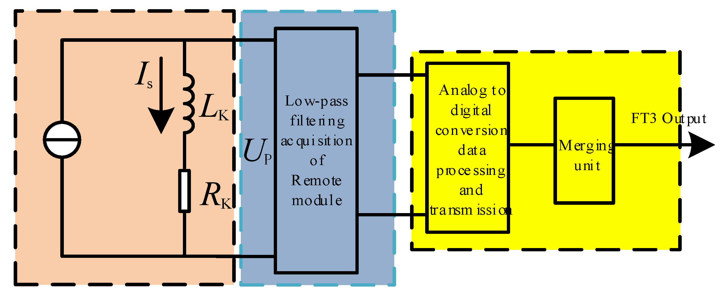
Figure 1. Schematic diagram of DC electronic transformer transmission link.
Energies 16 05727 g001
Figure 2. Equivalent test circuit topology.
Energies 16 05727 g002
Figure 3. Time delay equivalent test system based on complex multi-state current signal.
Energies 16 05727 g003
Figure 4. Transient step current waveform.
Energies 16 05727 g004
Figure 5. Schematic diagram of time delay extraction of typical transient step process.
Energies 16 05727 g005
Figure 6. Schematic diagram of field test equipment.
Energies 16 05727 g006
Figure 7. Curve of delay time versus frequency.
Energies 16 05727 g007
Figure 8. Curve of step signal.
Energies 16 05727 g008
Figure 9. Field test delay waveform of transient step current.
Energies 16 05727 g009
Disclaimer/Publisher’s Note: The statements, opinions and data contained in all publications are solely those of the individual author(s) and contributor(s) and not of MDPI and/or the editor(s). MDPI and/or the editor(s) disclaim responsibility for any injury to people or property resulting from any ideas, methods, instructions or products referred to in the content.