Article

Experimental Investigation on Thermal Performance of Vapor Chambers with Diffident Wick Structures

1
Jiangsu Key Laboratory of Micro and Nano Heat Fluid Flow Technology and Energy Application, School of Environmental Science and Engineering, Suzhou University of Science and Technology, Suzhou 215009, China
2
China National Institute of Standardization, Beijing 100088, China
*
Author to whom correspondence should be addressed.
Energies 2023, 16(18), 6464; https://doi.org/10.3390/en16186464
Submission received: 11 July 2023 / Revised: 17 August 2023 / Accepted: 4 September 2023 / Published: 7 September 2023
(This article belongs to the Special Issue Heat and Mass Transfer 2023)

Abstract

:
In this paper, a type of vapor chamber with a gradient pore size wick (VC-G) was developed, and its thermal performance was experimentally tested and compared with two types of VCs with uniform pore size wick (which can be defined as VC-U (200) and VC-U (50) as the powder size of the wick is 50-mesh and 200-mesh, respectively) and a VC without a wick (VC-N). In addition, a VC heat transfer ability experiment platform was built, and the thermal resistance, temperature distribution and thermal response time of the VC with different wick structures were experimentally investigated. The experiment results show that the capillary driving force provided by gradient pore size wick increases gradually from outside, which can not only promote the condensation fluid to gather in the central heat source but also facilitate the vapor to spread around. Therefore, compared with VC-U (200), VC-U (50) and VC-N, VC-G shows the best heat transfer performance, temperature uniform performance and start-up performance.

1. Introduction

The presence of thermal fatigue is a huge challenge to the safe operation of the system [1]. The vapor chamber (VC) transfers heat through the phase change of working fluid and has good temperature uniformity and thermal conduction performance. Therefore, this kind of device has a broad application in the field of heat dissipation, such as mobile phone and micro-electronic components [2]. In general, there is a wick filled in the VC so that the condensate can flow back to the evaporation surface under the capillary force induced by the porous structure when the vapor diffuses to the condensation surface. This is conducive to the circulation of the working fluid in the VC to ensure its heat transfer performance. A good wick is always marked by a large capillary force for flowing back of condensate and large permeability for the vapor. The common wicks include three types, which are the sintered wick, groove wick and mesh wick. Due to the characteristics of large capillary pressure and low cost, the sintered wick is widely used in VCs. However, the low permeability of the sintered wick for vapor limits the development of the VC’s heat transfer capacity [3]. Until now, numerous researchers have made various efforts to enhance the thermal performance of VCs with sintered wicks.
Since the permeability of a sintered wick for vapor is low, a special channel for vapor can improve its diffusing to the condensation surface [4,5]. Thus, grooves can be fabricated on the surface of a sintered wick [6,7]. Hwang et al. [8] processed grooves on the surface of a sintered wick and experimentally tested the heat transfer performance of the VC with this structure. The results showed that grooves can provide channels for vapor and reduce the vapor flow resistance to improve the VC’s heat transfer performance. In the experiment, the thermal resistance of the VC can be reduced to about 0.055 K/(W/cm2); the maximum heat transfer capacity is up to 580 W/cm2. Deng et al. [9,10] studied a wick with radial grooves, of which the center region is processed into a pool shape which is surrounded by the radial grooves. It found this structure of wick is not only beneficial to the separation vapor but also provides the liquid flow channel in the wick. It is convenient for the circulation of vapor and condensate to effectively improve the temperature uniformity of VC. In addition, they also studied the influence of power size on the VC’s thermal performance. Five kinds of sintered wicks with power diameters of <50, 50–75, 75–100, 100–125 and 125–150 μm were analyzed and compared. The results show that the best thermal performance is obtained when the wick is sintered by the power of 50–75 μm. Zhu et al. [11] conducted an experiment on the thermal performance of a VC with two parallel grooves in the sintered wick. The results show that the VC has minimum thermal resistance and maximum heat transfer limit when the width of groove in the sintered wick is 25 mm. In addition, the wick composited by the groove wick and screen-mesh wick has a high permeability and will make up for the deficiency of a sintered wick in permeability, so as to strengthen the thermal performance of the VC [12,13].
In addition to the groove, a biporous wick formed by two or more homogenous wicks is also beneficial for improving the performance of a VC, while a wick with smaller porosity produces high capillary force for the condensate and a wick with larger porosity increases the permeability for vapor [14]. Byon et al. [15] studied a VC filled with a wick with two sizes of 125/675 μm and found that this wick has the advantages of high permeability in the larger size wick and high capillary force in the small sintered wick. The capillary performance of the VC is 11 times higher than that of the VC with the wick of 125 μm in single size. Chen et al. [16] investigated the characteristics of a VC with a wick sintered by diamond and copper powder. Three kinds of wicks with different ratios of diamond and copper powder (1:4, 1:6 and 1:8) were tested. They showed that by adding diamond particles into the wick the heat transfer performance VC can be improved. The VC’s thermal resistance is smaller and temperature on the condensation surface is more uniform when the content of diamond particles is higher. The authors also experimentally studied the anti-gravity heat transfer performance of the VC with a radial gradient pore size mesh-type wick (200-mesh in the inner layer and 80-mesh in the outer layer) [17]. The research results indicated that the wick of the central 200-mesh has a higher capillary force to drive the condensate to the evaporation surface from the condensation surface. And a peripheral 80-mesh wick will reduce the flow resistance of vapor to spread to the condensation surface. Therefore, compared with the VC with single 80-mesh and 200-mesh wick, the VC with a gradient wick has smoother flowing of condensate and vapor, corresponding to better heat transfer performance.
The authors’ previous work [17] demonstrated that the gradient wick structure can improve the thermal performance of a vapor chamber. However, the contact thermal resistance between the mesh-type wick and the evaporator and condenser surfaces may limit its heat transfer performance. To address this issue, the authors designed and fabricated a sintered-type wick with a radial gradient pore size structure. A VC heat transfer ability experiment platform was built. The thermal resistance, temperature distribution and thermal response of the VC with different wick structures were experimentally investigated.

2. Experimental System and Method

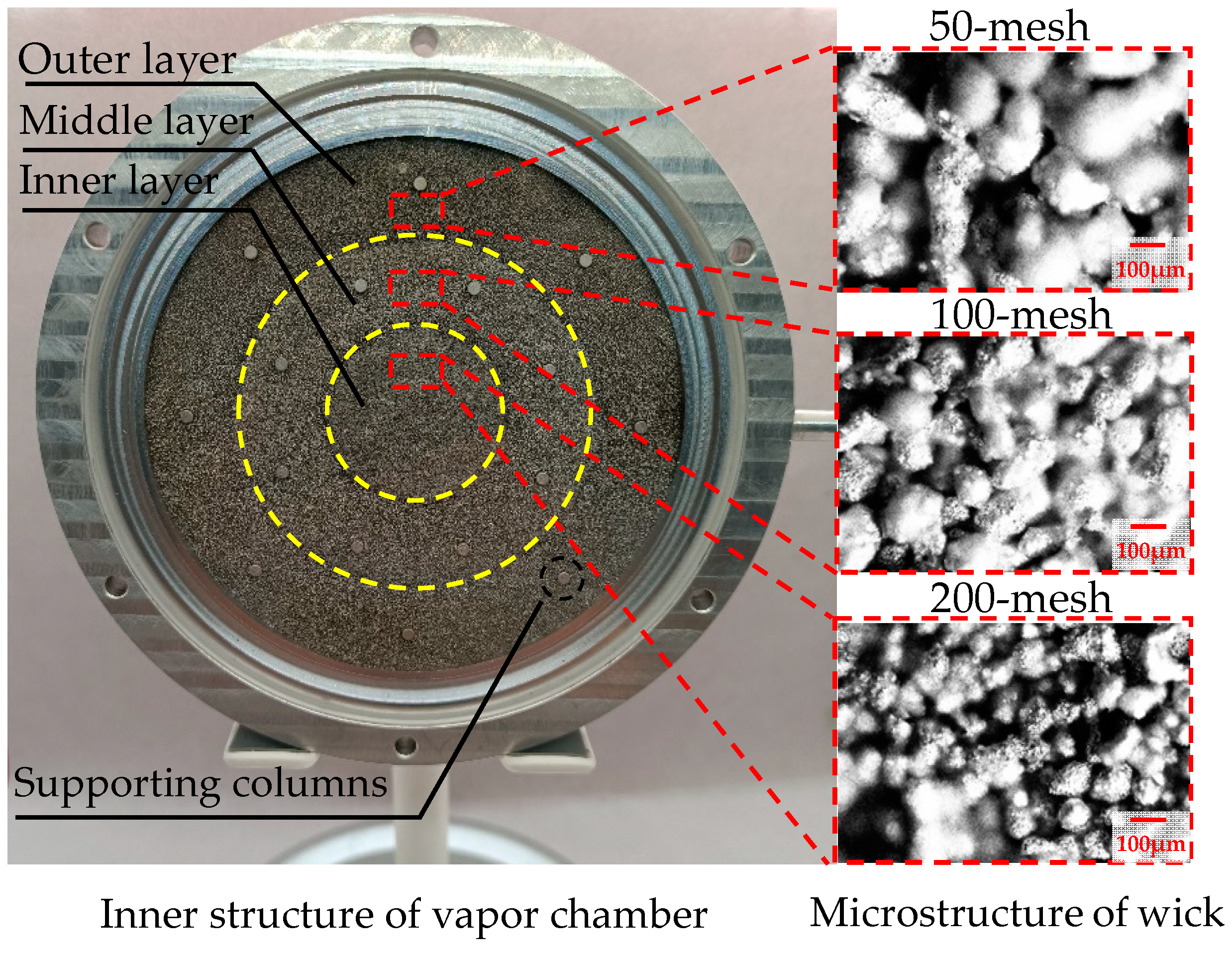
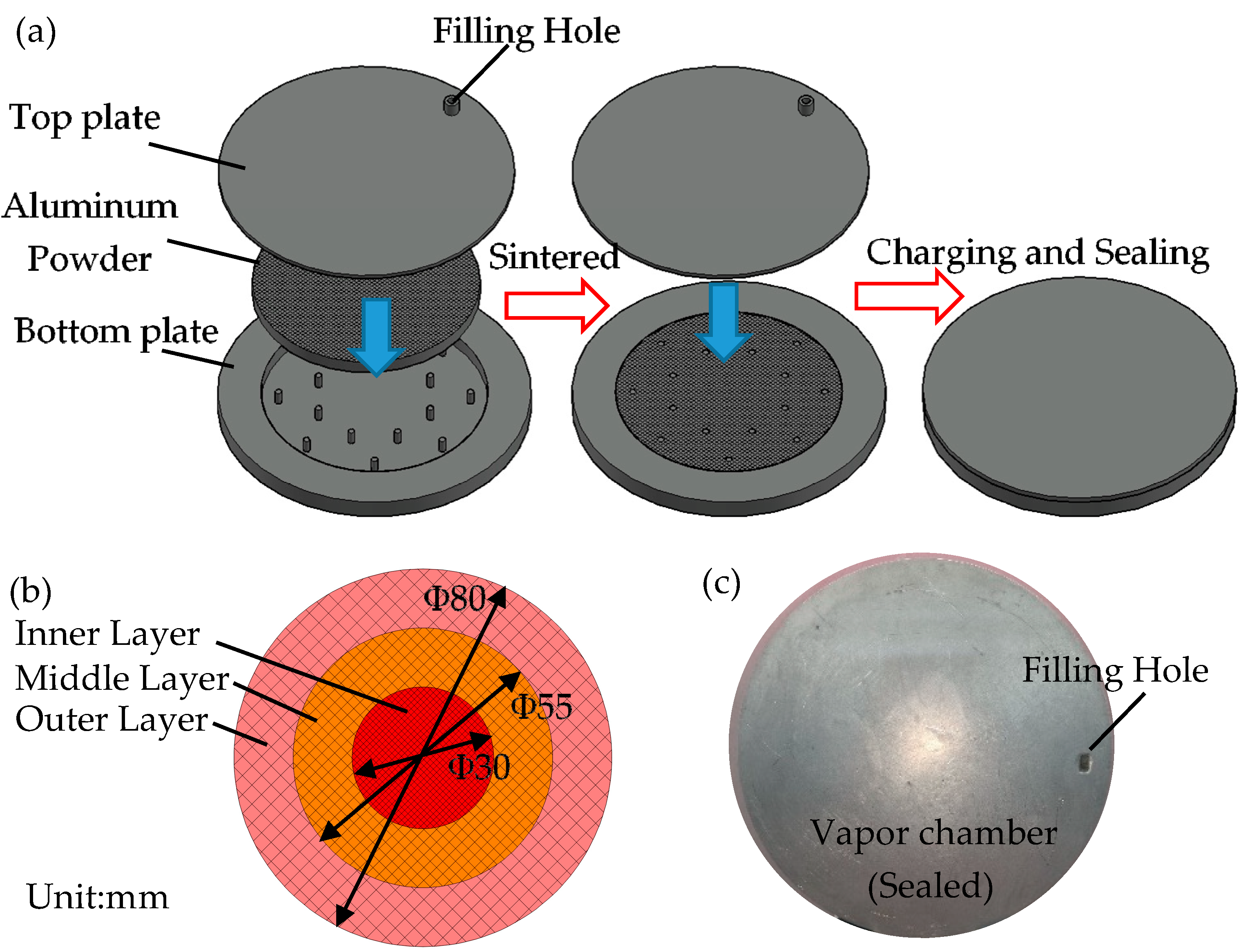
2.1. VCs with Different Wick Structures

In this experiment, the outer diameter and thickness of the VC were 110 mm and 9 mm, respectively. Both the evaporator and condenser plates were made of a 2 mm thick aluminum plate. The wick was sintered by using aluminum powder and contact with the top/bottom plate in close without any extra room for vapor flow with an overall diameter of 80 mm and thickness of 5 mm. During the manufacturing of the vapor chamber, the aluminum powder was tightly filled in the space formed by the bottom plate and top plate. In addition, the aluminum powder was compressed during the sintering. Therefore, the wick formed after sintering is in close contact with the top/bottom plate. The contact mechanical strength was thus guaranteed, and small thermal resistance between the top/bottom plates and the sintered wick was also realized. The local microstructure of the gradient wick is given in Figure 1. The particle size of aluminum powder increased in steps from the center to the outside, and the gap size between particles also increased in steps, forming a wick structure of 200 mesh, 100 mesh and 50 mesh, respectively. Figure 2 shows the schematic diagram of the vapor chamber; Table 1 shows the various parameters of the VC with different wicks. Among them, the gradient wick can be divided into inner, middle and outer layers. The inner, middle and outer wicks were made with sintered aluminum powder with sizes of 200-mesh (0.074 mm), 100-mesh (0.15 mm) and 50-mesh (0.28 mm), respectively. The three layers of the wick had diameters of 30 mm, 55 mm and 80 mm. In addition, to prevent deformation or damage of the VC due to thermal stress or extrusion, supporting columns with the same shell material were used in the VCs. In order to comparatively study the influence of wick structures on the performance of VCs, the VCs with a uniform wick using 200-mesh aluminum powder (VC-U (200)) and 50-mesh aluminum powder (VC-U (50)) and the VC without the wick (VC-N) were fabricated. In this study, acetone was used as the working fluid, and the filling rate (the working fluid volume ratio of the internal VC volume) was 80%. The properties of acetone at the saturation conditions are given in Table 2.

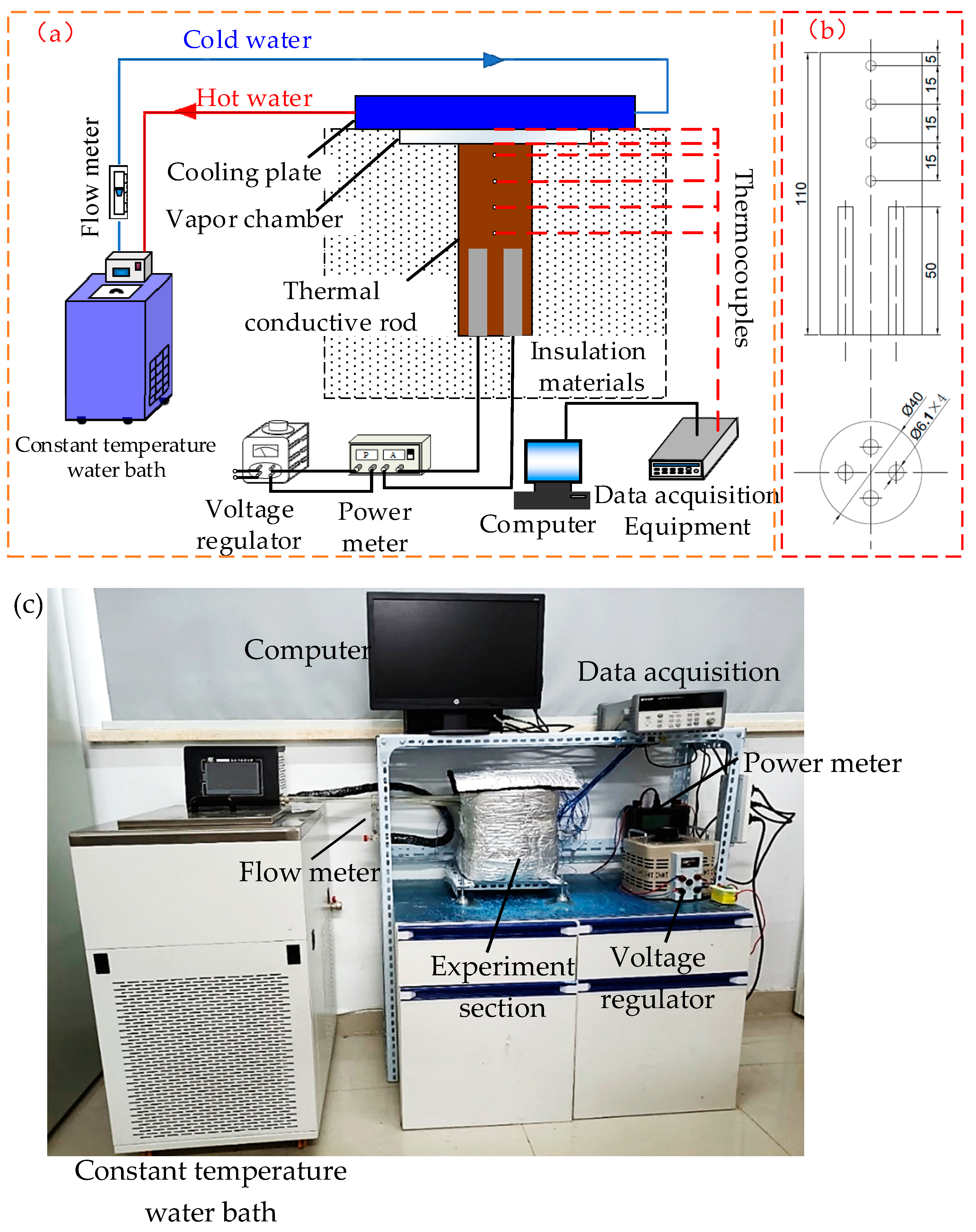
2.2. Experimental System

Figure 3 shows the schematic diagram of the VC performance test system. The experimental system is mainly composed of four parts: the VC, the controllable heating system, the cooling system and the data acquisition system.
The controllable heating system consists of a voltage regulator, power meter and heating rod. The thermal conductive rod is a cylinder as shown in Figure 2. Four of the same cartridge heaters with a diameter of 6 mm and a length of 50 mm were inserted in the copper thermal conductive rod to provide heat input required during experiment. The diameter and height of the rod were 20 mm and 110 mm. Four T-type thermocouples (±0.5 °C) with a distance of 15 mm were inserted into the holes deep into the rod axis to measure the rod’s temperature along the axis. Then the heat flux applied to the heating surface and the heating surface temperature (Th) can be obtained by Fourier’s law of heat conduction.
In the cooling system, the water from a constant-temperature water bath flows into the cooling tank which contacts the VC, takes the released heat and then flows back to the constant-temperature water bath. The flowmeter is used to measure the flow rate of the circulating water. During the experiment, circulating water flow rate was set at 100 mL/min. In addition, thermocouples were installed at the inlet and outlet of the cooler to measure the temperature change of the circulating water. To record the temperature during the experiment, there were 7 temperature measuring points on both the evaporation surface (T1T7) and condensation surface (T8T14), as shown in Figure 4. Based on a pre-experiment that found a small temperature difference between the arrangement of the thermocouples in an “L” shape and straight shape, the L-shaped arrangement for the thermocouples was adopted in the formal experiment because it could provide a more intuitive visualization of the temperature distribution and the uniformity of the vapor chamber since the heat spreads from the center of the VC towards the periphery. All the temperatures were recorded by the data acquisition instrument.
Table 3 shows the temperatures on evaporation surface from the repeatable experiment. As seen, the standard deviation for the repeatable experiment is quite small, which proves good repeatability for the experiment.

2.3. Data Analysis

The total thermal resistance ( R t o t ) is introduced to evaluate the VC thermal performance. It is determined as:
R t o t = T h T ¯ c Q i n
where Q i n is the actual heat input, T ¯ c is the average temperature of condensation surface, and T h is the temperature at the center of the evaporation surface. The input heat Q i n applied by the copper rod can be determined by the one-dimensional differential equation for heat conduction:
Q i n = λ A d T d z
where λ represents the thermal conductivity, A is the heat transfer area of the heating rod, dT/dz is the temperature gradient along the z-direction, and the orientation of axis z represents the longitude direction of the thermal conductive rod, where the original point (0,0,0) is at the center point on the bottom surface of the rod.
The temperature uniformity coefficient is used to evaluate surface temperature uniformity of the evaporation and condensation surface, which is expressed as the following:
s = 1 n i = 1 n ( T ¯ T i ) 2
where s is the temperature uniformity coefficient and n and T ¯ are the number of thermocouples on condensation surface or the evaporation surface, respectively. T i represents the temperature of the ith thermocouple on the condenser surface or the evaporation surface.
Due to the same working principle with the heat pipe, the vapor chamber can be regarded as a special shaped heat pipe. In addition, both heat pipe and vapor chamber can be seen as a first-order response system since the average temperature variation of heat pipe and vapor chamber basically follows a first-order response curve [18], it is reasonable to use the time constant (which is defined as the time it takes for a system’s response to reach approximately 63.2% of its final value) to evaluate the startup process of heat pipes [19]. So far, this evaluation method has been successfully introduced into the evaluation of the starting characteristics of heat pipes [20]. In fact, this method was already used by Wang et al. [21] to evaluate the startup performance of a flat heat pipe in their investigation. Therefore, we believe this method can also be used for the evaluation of the starting characteristics of a vapor chamber since the temperature response of a VC is quite similar to that of heat pipe. Vapor chamber start-up characteristics can be described by the unit step response function of a first-order system, which can be expressed as:
T s t t = T s t e a d y 1 e t τ ,   τ   0
where Tst(t) is the average temperature of evaporation surface at time t, Tsteady is the average temperature of evaporation surface at steady state, t is the time of heat duration, and τ is the startup time constant.
Based on data error analysis, this paper analyzes the uncertainty of different parameters. Assuming that the direct measured parameters (such as temperature T) observe uniform distribution within the interval, the type B uncertainty of T can be expressed as follows:
U T = ε T 3
However, for the indirect measured parameters (including total thermal resistance, heat input and temperature uniformity coefficient), the uncertainty can be calculated by the following equation:
σ y = f x 1 2 σ x 1 2 + f x 2 2 σ x 2 2 + + f x n 2 σ x n 2 1 / 2
where σ y   is the measurement error of the indirectly measured parameter and σ x 1 , σ x 2 , …, σ x n , are the measurement error of each of the directly measured parameters.
In the experiment, the measurement accuracy of the T-type thermocouples used in this experiment is ±0.5 °C. Combining Equations (1)–(6), the maximum uncertainties of the main parameters can be obtained, which are listed in Table 4.

3. Results and Discussion

To gain insight into the impact of the wick structure, experiments were conducted to compare the heat transfer performance of different vapor chambers under the same conditions of heat flux (q) ranging from 2 to 20 W/cm2, cooling water temperature of 20 °C and cooling water flow of 100 mL/min.

3.1. Heat Transfer Performance of VC with Different Wick Structures

Figure 5 shows the average temperature difference between evaporator and condenser surfaces of VCs with different wick structures. It can be seen that due to the increase of heat flux, the average temperature difference significantly increased for all VCs in the current study. Especially for the VC without wick, the average temperature difference between the evaporation surface and condensation surface is much larger due to the lack of backflow with the help of the wick structure. For instance, when the heat flux is above 20 w/cm2, the temperature difference is more than 100 °C, which indicates that the flow of vapor and condensate is difficult and the heat release from hot wall due to the phase change is not effective. If there is wick in the VC, the condensate can quickly flow back to the evaporation area under the capillary force due to the pore structure in the wick. In general, the capillary force is larger when the pore size is smaller. And the flowing back of condensate is more intense to the evaporation surface, which leads to the lower evaporation surface temperature. Therefore, as shown in Figure 5, average temperature difference between the evaporator and condenser surface for the VC with uniform wick of 200 mesh, of which the pore size is smaller, is lower than that for the VC with uniform wick of 50 mesh during the running of the VC. In addition, heat transfer performance of the VC not only depended on the flow back of condensate but also on the transfer of vapor to the condensation surface from the evaporation surface. However, the flow resistance of vapor is higher in the wick with a smaller pore size. Obviously, it is a contradiction between a highly efficient condensate flowback and a low flow resistance vapor transfer in the same pore size. However, in the VC with a gradient wick, the vapor can diffuse to the condensation surface with a bigger size pore with low flow resistance, and the condensate can be sucked to the evaporation surface through the smaller size pore with a larger capillary force. Therefore, as shown in Figure 5, the average temperature difference between the evaporator and condenser surface of the VC-G is less than that of the VC-N, VC-U (50) and VC-U (200) due to the better heat transfer performance based on the more efficient mass transfer between the two surfaces.
The fluid flow in the VC affects not only the temperature difference between condensation and evaporation surfaces but also the thermal resistance of the VC, which is another important indicator of thermal performance. Figure 6 compares the thermal resistance of VCs with different wick structures under different conditions. As shown in the figure, the thermal resistance of the VC without wick is much larger than that of the VCs with uniform wick and gradient wick, which is because the transfer of vapor and condensate between the evaporation and condensation surfaces is much more difficult. Since the gradient wick in the VC is beneficial to both the transport of vapor to condensation surface and the flow back of condensate to evaporation surface, both the transfer of heat from the heat source to the VC by boiling of liquid and from the VC to the outside by condensation of vapor are efficient. Therefore, the thermal resistance of the VC with gradient wick is lower than that of the VC with uniform wick.
In addition to thermal resistance, the uniformity of surface temperature distribution is also an important aspect for evaluating the heat transfer performance of VC. Figure 7 shows the steady temperature distribution on the evaporation surface of the VCs with different wicks under the same condition with the heat flux of 20 W/cm2. It can be seen from the figure that the surface temperature decreases from the center to the periphery region for all VCs due to the location of heat recourse, respectively. In addition, the VC without wick has the highest overall surface temperature, while the VC with gradient wick has with the lowest surface temperature. This indicates that the heat cannot transfer to the condensation surface from the evaporation surface in time for the VC without wick. However, a driving force on the condensate induced by the wick ensures more efficient heat transfer. Furthermore, by being close to the heat source, the temperature of the central evaporation surface of the VC with different wick structures is much higher than the surrounding temperature. For different VCs under the same condition, this temperature is above 170 °C for the VC without wick and is lower than 90 °C for the VC with a gradient wick. This is also due to the different heat transfer performance with the flow characteristics of vapor and condensate in VCs with different wicks. From Figure 7, it can be seen that the local hot spot can be effectively prevented in the VC with a gradient wick.
Figure 8 compares the distribution of the steady-state condensation surface temperature of VCs with different wicks when the heat flux is 20 W/cm2. It can be seen from the figure that the temperature of the condensation surface of the VC without a wick is the most uniform; however, the overall temperature is the highest. By comparison, the condensation surface of the VC with a gradient wick has the least temperature uniformity and lowest overall temperature level. These are all related to the distribution of vapor and condensate in the VC. In the VC without a wick, the vapor can spread out from the hot surface to the condensation surface with low resistance, so the condensation surface temperature is more uniform in the VC without a wick. However, after condensation, a liquid film is brought out on the inner condensation wall [22], which increases the condensation heat transfer resistance. In this case, the heat is harder to release from the VC, and the condensation surface temperature is higher. If there is a wick in the VC, the condensate film on the condensation surface can flow back to the evaporation surface in time by the capillary force, and coupled with the thermal conduction of the wick structure, the heat transfer resistance is reduced, and the heat can be transferred to the condenser surface from the central area of evaporation surface more easily and then taken away by the cooling water more quickly. As a result, the overall temperature level of the VC-G is lower than the VC-N. However, it is obvious that the flow resistance is higher in the VC-G when compared with an empty space for vapor spreading. Therefore, the condensation surface temperature gradient of the VC-G from the center to the periphery is higher than that of the VC-N.
Figure 9 shows the temperature distribution on the evaporation surface and condensation surface under different heat flux. As shown, with the increase in heat flux density, there is an overall rise in the temperature of the heat transfer plate for both the evaporation surface and condensation surface. For the evaporation section, a higher evaporation temperature is needed to realize enough of an evaporation rate so that the vapor chamber can obtain a higher heat transfer capacity as more heat needs to be transferred with the increase of heat flux. Since the vapor chamber is heat in the central area, the temperature of the center rises more obviously when comparing it to the edge area of the vapor chamber. Therefore, a larger temperature gradient from the center to the sides under a higher heat flux can be seen in Figure 9b. However, for the condensation surface, it is seen that a uniform temperature distribution can be maintained even though the heat flux has reached 20 W/cm2, which proves a good radial heat transport capability of the vapor chamber with a gradient wick.
Figure 10 shows the evaporation surface temperature uniformity coefficient under the heat flux of VCs with different wick structures. It can be seen that the temperature uniformity coefficient of the evaporation surface increases with the increase of heat flux. And the VC without a wick and the VC with gradient a wick show the largest and smallest increases in rate, respectively. In addition, it can also be seen that the evaporation surface temperature uniformity coefficient of the VC with a gradient wick is always lower than that of other VCs, and the VC without a wick has the largest condensation surface temperature uniformity coefficient. This is because the condensate cannot easily flow back to the heating area in the VC without a wick, and there is not enough liquid to evaporate to transfer the heat to the condensation surface. So, the local temperature at the center evaporation surface is high. If there is a wick in the VC, the capillary force induced by the pore structure can drive the condensate to flow back to the evaporation side to improve the thermal performance. Therefore, the evaporation surface temperature uniformity coefficient of the VC with a uniform wick is smaller than that of the VC without a wick. In addition, since the condensate flow resistance in a 50-mesh uniform wick is bigger than in a 200-mesh uniform wick, the temperature uniformity coefficient of a VC with 200-mesh uniform wick is lower. However, the gradient wick can not only ensure that the condensate flows back smoothly but also reduce the vapor diffusion resistance compared with the uniform wick. Therefore, the VC with a gradient wick has the best thermal performance and the lowest evaporation surface temperature uniformity coefficient.
Figure 11 presents the temperature uniformity coefficient of the condensation surface of the VCs with different wicks under different heat flux. With the increase of heat flux, the condensation surface temperature uniformity coefficient increases for all VCs with different wicks. It can also be seen from the figure that the condensation surface of the VC without a wick has the lowest temperature distribution uniformity coefficient, and the coefficient of the VC with a 50-mesh uniform wick is the highest. As mentioned above, with the wick is filled in the VC, the heat transfer performance is improved. However, the wick enhances the vapor flow resistance and hinders the radial spread of heat on the condensing surface. Therefore, temperature distribution uniformity coefficient of the condensation surface of the VC with a wick is higher than that of the VC without a wick. In addition, since the gradient wick benefits the vapor flow in the wick, the temperature distribution uniformity of the VC with a gradient wick is lower than the VCs with a uniform wick.

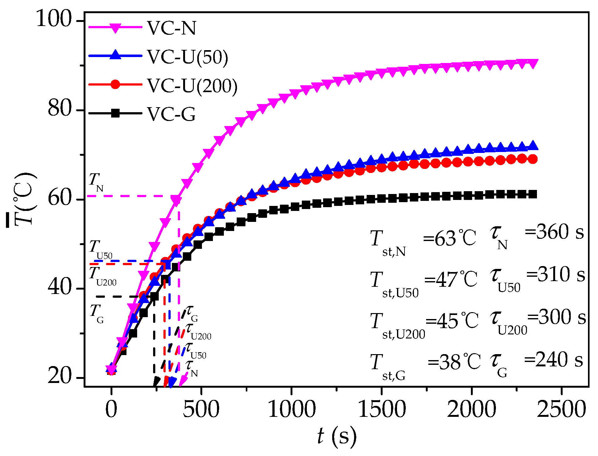
3.2. Start-Up Performance of VC with Different Wick Structures

Figure 12 shows the variation of the average evaporation surface temperature of VCs with different wicks. As shown in the figure, under the condition of the heat flux density of 20 W/cm2, the average evaporation surface temperature first rises rapidly and then increases gradually and smoothly. In addition, it can be seen that the average evaporation surface temperature of the VC with a gradient wick is always lower than that of other VCs and is also rising more slowly. From Figure 11, it is found that the average evaporation surface temperature of the VC with a gradient wick reaches the 63.2% of its maximum value in about 240 s (Tst,G), which is the fastest. For the VC-U (200) and VC-U (50), the evolutions of average evaporation surface temperature are basically the same: the average temperature reaches the 63.2% of its maximum value in about 300 s (Tst,U200) and 310 s (Tst,U50), respectively. However, for the VC without a wick, the average evaporation surface temperature is the highest and reaches 63.2% of its maximum value in about 360 s(Tst,N). This indicates that the VC-G has the fastest thermal response speed and the best start-up performance, while the VC without a wick has the worst start-up performance.
Figure 13 and Figure 14, respectively, show the variation of the condensation surface temperature distribution of the VC without a wick and the VC with a gradient wick at the heat flux of 20 W/cm2. It can be found that in the initial stage the increase of the condensation surface temperature of the VC with a gradient wick is much more rapid, and the temperature difference between the center (T4) and the surrounding area is bigger. This indicates that the thermal response time of the VC with a gradient wick is shorter, and the heat can transfer to the condensation surface more efficiently.
To determine the continuous working ability under variable heat conditions, the VC was heated continuously at 2 W/cm2, and the heating power was increased in 2 W/cm2 increments once the VC reached a steady state. As shown in Figure 15, the average temperature of the evaporating surface ( T ¯ e ) was recorded. During the initial heating stage, a new steady state was reached quickly. As the heat input increased, a shorter time was needed to reach a new steady state and higher temperatures were required. However, the VC continued to function normally under high heat load. When the power was increased from 2 W/cm2 to 10 W/cm2, a small temperature difference was enough to reach a new steady state but takes a longer time, which means the circulation rate of the working fluid is small. On the contrary, a larger temperature difference was required to reach the new steady state due to more heat input when the heat input was larger than 10 W/cm2, which promotes the evaporation rate of the working fluid in the vapor chamber. As a result, the circulation of the working fluid inside was accelerated, and the new steady state was achieved sooner.

4. Conclusions

The thermal performance of the VC with a gradient wick was studied and compared with that of a VC with a uniform wick and without a wick. Under the same experiment conditions, the thermal resistance, surface temperature distribution characteristic and start-up performance of VCs with different wicks were analyzed. In summary, the conclusions are as follows:
(1)
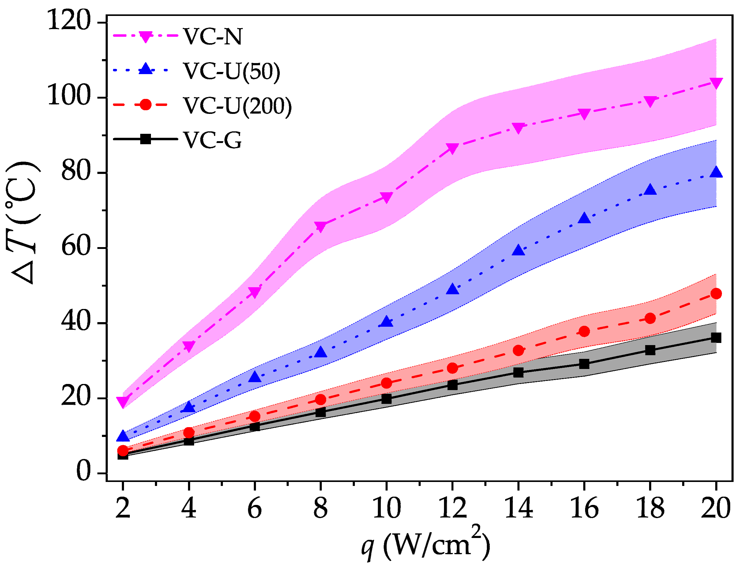
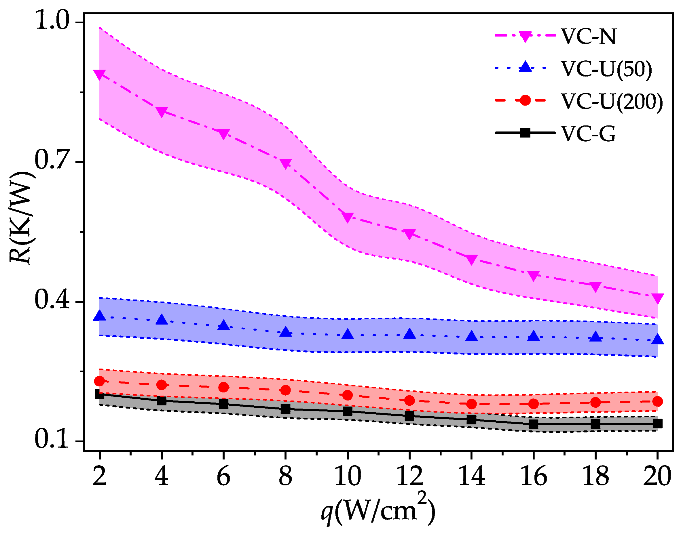
Benefiting from the gradient wick structure, the VC with a gradient wick has the smallest thermal resistance due to the smoothest vapor-condensate circulation when compared with the VCs with a uniform wick and without a wick.
(2)
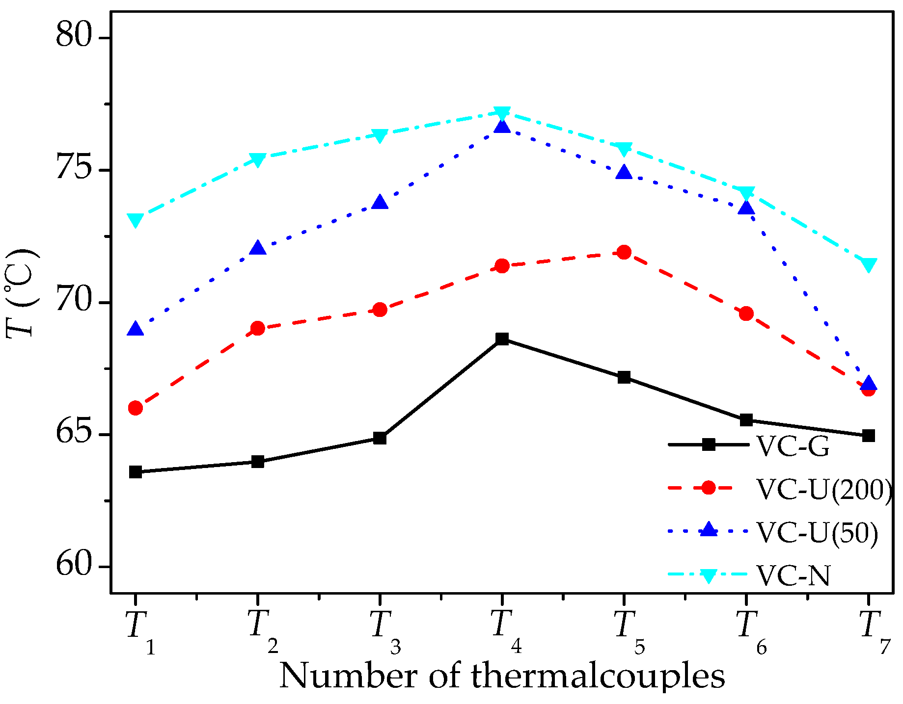
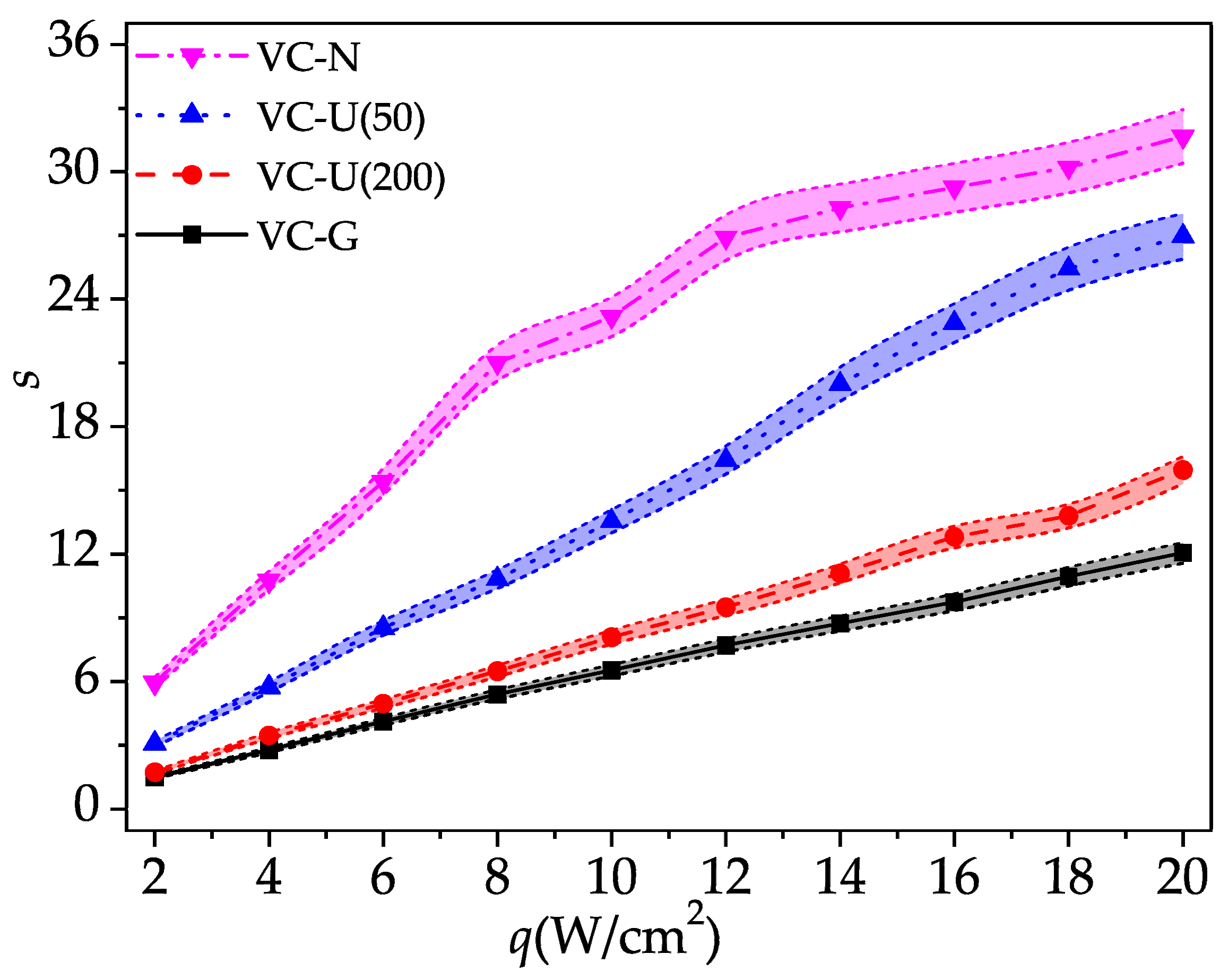
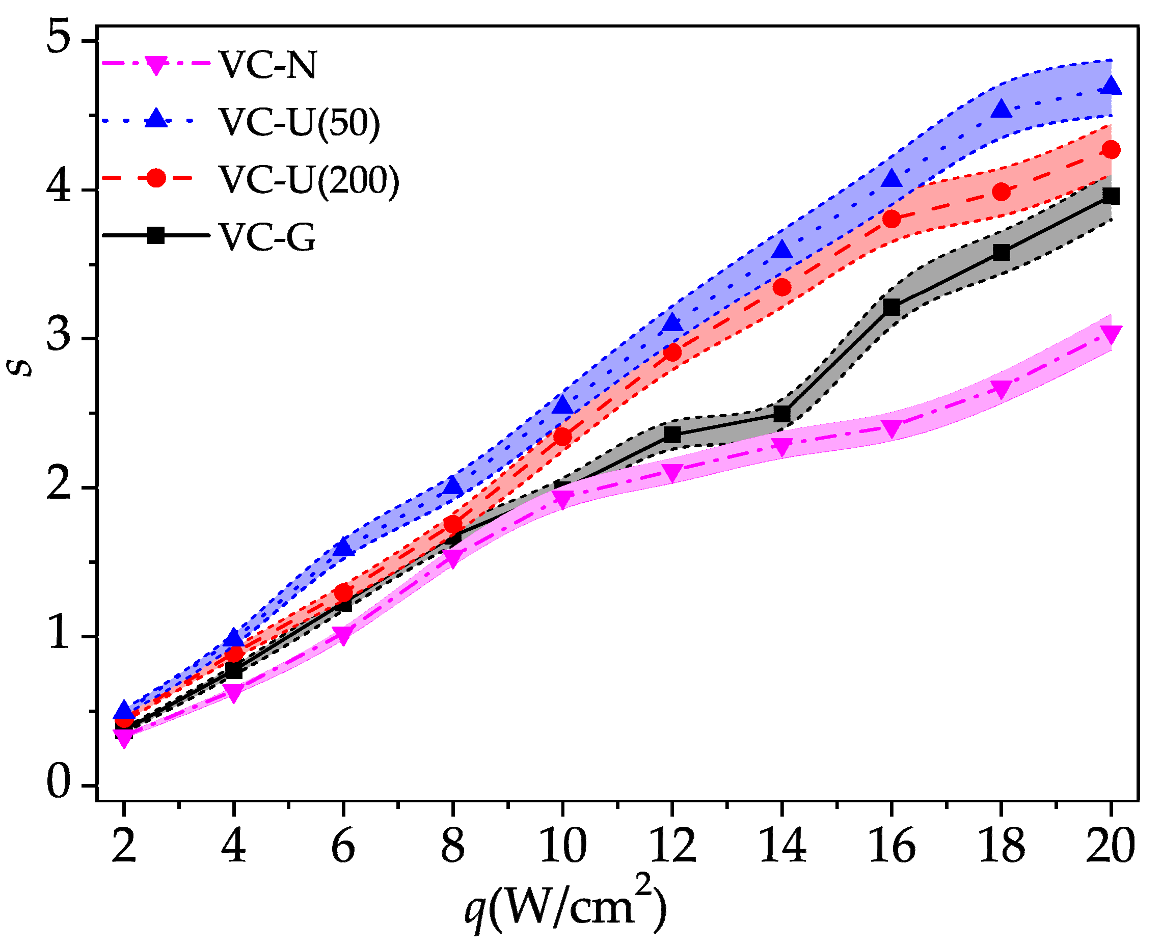
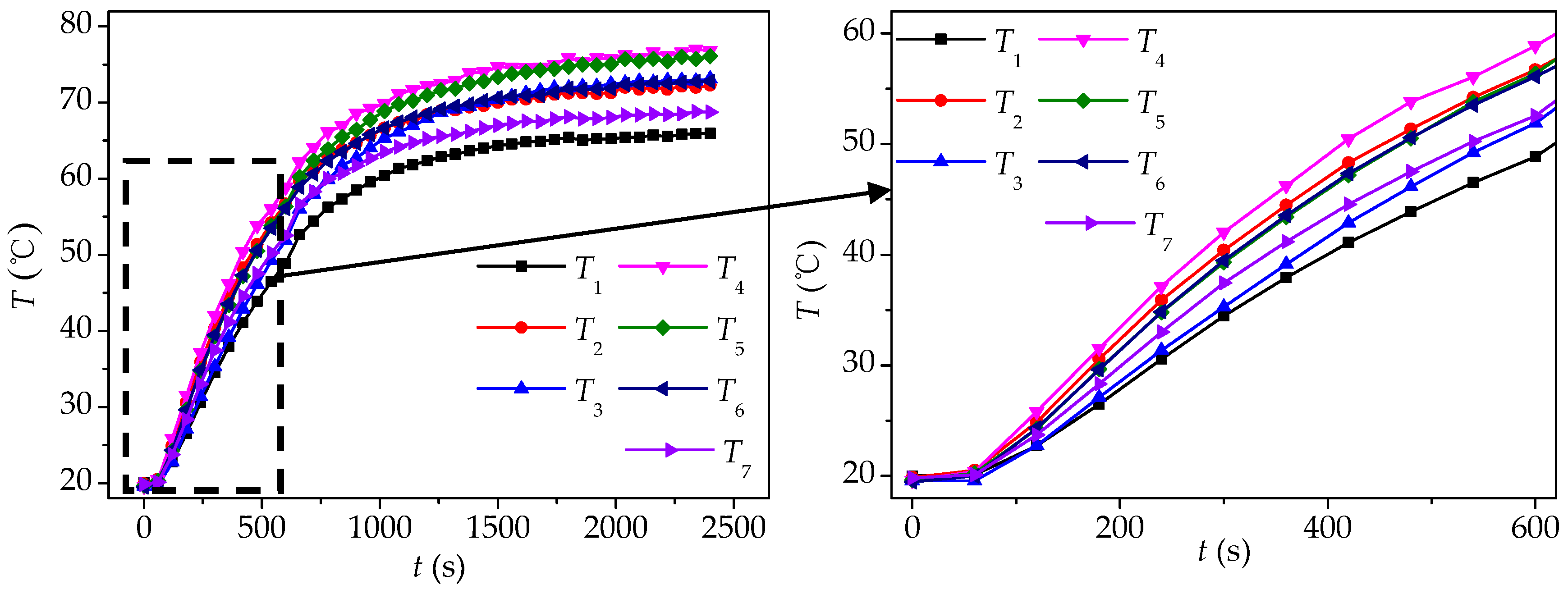
The temperature of the evaporation surface of the VC with a gradient wick is more uniform than that of the VC with a uniform wick and without a wick. The temperature distribution uniformity coefficients of the evaporation surface increase with the increased heat flux.
(3)
As the flow resistance is higher in the VC-G when compared with an empty space for vapor spreading, the condensation surface temperature gradient of the VC-G from the center to the periphery is higher than that of the VC-N.
(4)
Under the same heat flux, the average evaporation surface temperature of the VC with a gradient wick is the lowest and reached stability in the shortest time. In addition, for the VC with a gradient wick, the average temperature reaches 63.2% of its maximum value in about 240 s, which is the fastest. That is to say, the VC-G has the best start-up performance.
(5)
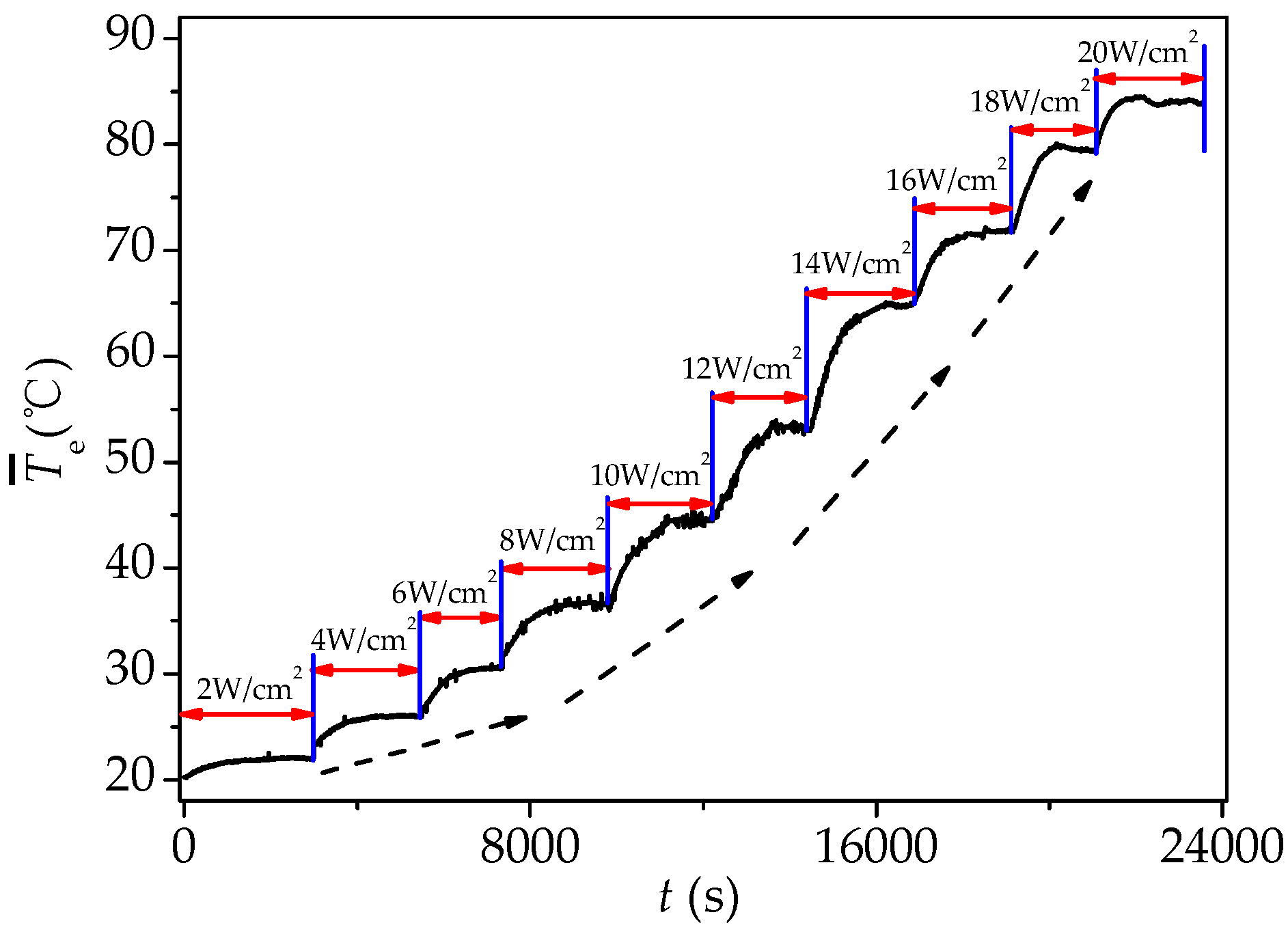
Higher temperature difference and shorter time are needed for the VC-G to reach a new steady state when the heat flux increases.
In this experiment, the charging hole of the vapor chamber was totally sealed off when manufacturing, and the filling rate of the working fluid cannot be changed during the experiment. Limited by this, the optimal filling ratio and working fluids cannot be determined. However, the effects of working fluids and filling ratio will be further studied in our future work to determine the optimal working performance for this type of vapor chamber.

Author Contributions

Investigation, Y.X.; Writing—review & editing, M.W.; Supervision, F.Y. All authors have read and agreed to the published version of the manuscript.

Funding

This work was supported by the National Natural Science Foundation of China (Grant No. 51906170).

Data Availability Statement

The data presented in this study are available on request from the corresponding author.

Conflicts of Interest

The authors declare no conflict of interest.

References

  1. Wu, L.; Han, X.; Shao, C.; Yao, F.; Yang, W. Thermal Fatigue Modelling and Simulation of Flip Chip Component Solder Joints under Cyclic Thermal Loading. Energies 2019, 12, 2391. [Google Scholar] [CrossRef]
  2. Faghri, A. Review and Advances in Heat Pipe Science and Technology. J. Heat Transf. 2012, 134, 123001. [Google Scholar] [CrossRef]
  3. Sudhakar, S.; Weibel, J.A.; Zhou, F.; Dede, E.M.; Garimella, S.V. Area-scalable high-heat-flux dissipation at low thermal resistance using a capillary-fed two-layer evaporator wick. Int. J. Heat Mass Transf. 2019, 135, 1346–1356. [Google Scholar] [CrossRef]
  4. Li, Y.; Zhou, W.; Li, Z.; Chen, Z.; Gan, Y. Experimental analysis of thin vapor chamber with composite wick structure under different cooling conditions. Appl. Therm. Eng. 2019, 156, 471–484. [Google Scholar] [CrossRef]
  5. Wang, M.; Cui, W.; Hou, Y. Thermal spreading resistance of grooved vapor chamber heat spreader. Appl. Therm. Eng. 2019, 153, 361–368. [Google Scholar] [CrossRef]
  6. Tang, Y.; Deng, D.; Lu, L.; Pan, M.; Wang, Q. Experimental investigation on capillary force of composite wick structure by IR thermal imaging camera. Exp. Therm. Fluid Sci. 2010, 34, 190–196. [Google Scholar] [CrossRef]
  7. Wang, J.; Catton, I. Enhanced evaporation heat transfer in triangular grooves covered with a thin fine porous layer. Appl. Therm. Eng. 2001, 21, 1721–1737. [Google Scholar] [CrossRef]
  8. Hwang, G.; Fleming, E.; Carne, B.; Sharratt, S.; Nam, Y.; Dussinger, P.; Ju, Y.; Kaviany, M. Multi-artery heat-pipe spreader: Lateral liquid supply. Int. J. Heat Mass Transf. 2011, 54, 2334–2340. [Google Scholar] [CrossRef]
  9. Deng, D.; Huang, Q.; Xie, Y.; Huang, X.; Chu, X. Thermal performance of composite porous vapor chambers with uniform radial grooves. Appl. Therm. Eng. 2017, 125, 1334–1344. [Google Scholar] [CrossRef]
  10. Wang, Q.-H.; Zhao, H.; Xu, Z.-J.; Li, J.-R.; Deng, D.-X. Numerical analysis on the thermal hydraulic performance of a composite porous vapor chamber with uniform radial grooves. Int. J. Heat Mass Transf. 2019, 142, 118458. [Google Scholar] [CrossRef]
  11. Zhu, M.; Huang, J.; Song, M.; Hu, Y. Thermal performance of a thin flat heat pipe with grooved porous structure. Appl. Therm. Eng. 2020, 173, 115215. [Google Scholar] [CrossRef]
  12. Wiriyasart, S.; Naphon, P. Thermal performance enhancement of vapor chamber by coating mini-channel heat sink with porous sintering media. Int. J. Heat Mass Transf. 2018, 126, 116–122. [Google Scholar] [CrossRef]
  13. Liu, W.; Peng, Y.; Luo, T.; Luo, Y.; Huang, K. The performance of the vapor chamber based on the plant leaf. Int. J. Heat Mass Transf. 2016, 98, 746–757. [Google Scholar] [CrossRef]
  14. Velardo, J.; Date, A.; Singh, R.; Nihill, J.; Date, A.; Phan, T.L.; Takahashi, M. Experimental investigation of a vapour chamber heat spreader with hybrid wick structure. Int. J. Therm. Sci. 2019, 140, 28–35. [Google Scholar] [CrossRef]
  15. Byon, C.; Kim, S.J. Capillary performance of bi-porous sintered metal wicks. Int. J. Heat Mass Transf. 2012, 55, 4096–4103. [Google Scholar] [CrossRef]
  16. Chen, Y.-T.; Miao, J.-M.; Ning, D.-Y.; Chu, T.-F.; Chen, W.-E. Thermal performance of a vapor chamber heat pipe with diamond-copper composition wick structures. In Proceedings of the 4th International Microsystems, Packaging, Assembly and Circuits Technology Conference, Taipei, Taiwan, 21–23 October 2009; pp. 340–343. [Google Scholar] [CrossRef]
  17. Yao, F.; Miao, S.; Zhang, M.; Chen, Y. An experimental study of an anti-gravity vapor chamber with a tree-shaped evaporator. Appl. Therm. Eng. 2018, 141, 1000–1008. [Google Scholar] [CrossRef]
  18. Liu, X.; Chen, Y.; Shi, M. Dynamic performance analysis on start-up of closed-loop pulsating heat pipes (CLPHPs). Int. J. Therm. Sci. 2013, 65, 224–233. [Google Scholar] [CrossRef]
  19. Liu, X.; Chen, Y. Transient thermal performance analysis of micro heat pipes. Appl. Therm. Eng. 2013, 58, 585–593. [Google Scholar] [CrossRef]
  20. Chen, Y.P.; Yao, F.; Shi, M.H. Thermal response of a heat pipe with axially “Omega”-shaped microgrooves. Int. J. Heat Mass Transfer. 2012, 55, 4476–4484. [Google Scholar] [CrossRef]
  21. Wang, Y.; Vafai, K. Transient characterization of flat plate heat pipes during startup and shutdown operations. Int. J. Heat Mass Transf. 2000, 43, 2641–2655. [Google Scholar] [CrossRef]
  22. Hu, Y.; Cheng, J.; Zhang, W.; Shirakashi, R.; Wang, S. Thermal performance enhancement of grooved heat pipes with inner surface treatment. Int. J. Heat Mass Transf. 2013, 67, 416–419. [Google Scholar] [CrossRef]
Figure 1. The gradient wick structure of the vapor chamber.
Energies 16 06464 g001
Figure 2. Schematic diagram of the vapor chamber: (a) The manufacturing process; (b) Dimensions of wick structure; (c) Pictures of vapor chamber after sealing.
Energies 16 06464 g002
Figure 3. The schematic diagram of the performance test system: (a) Experimental system diagram; (b) Dimensional drawing of the thermal conductive rod; (c) Rig of experimental system.
Energies 16 06464 g003
Figure 4. Distribution of temperature measurement points.
Energies 16 06464 g004
Figure 5. Average temperature difference between evaporator and condenser surfaces of VCs with different wick structures.
Energies 16 06464 g005
Figure 6. Thermal resistance of VCs with different wick structures.
Energies 16 06464 g006
Figure 7. Steady-state temperature distribution on evaporation surface of VCs with different wick structures (q = 20 W/cm2).
Energies 16 06464 g007
Figure 8. Steady-state temperature distribution on condensation surface of VCs with different wick structures (q = 20 W/cm2).
Energies 16 06464 g008
Figure 9. Temperature distribution on (a) evaporation surface and (b) condensation surface under different heat flux.
Energies 16 06464 g009
Figure 10. Variation of evaporation surface temperature uniformity coefficient of VCs with different wicks under different heat flux.
Energies 16 06464 g010
Figure 11. Variation of condensation surface temperature uniformity coefficient of VCs with different wicks under different heat flux.
Energies 16 06464 g011
Figure 12. Variation of average temperature with time on evaporation surface of VCs with different wick structures (q = 20 W/cm2).
Energies 16 06464 g012
Figure 13. Variation of temperature distribution with time on the condensation surface of VC-N (q = 20 W/cm2).
Energies 16 06464 g013
Figure 14. Variation of temperature distribution with time on the condensation surface of VC-G (q = 20 W/cm2).
Energies 16 06464 g014
Figure 15. Variation of average temperature of evaporation surface with heat flux.
Energies 16 06464 g015
Table 1. Various parameters of VC with different wick structures.
VC-GVC-U (200) VC-U (50) VC-N
Wick structureAperture (mesh)200/100/5020050
Outside diameter (mm)30/55/808080
Thickness (mm)555
Table 2. The properties of acetone at the saturation conditions.
ParametersValueUnit
20 °C120 °C
Density (liquid)790660.3kg/m3
Density (vapor)0.6411.02kg/m3
Specific heat (liquid)2.162.61kJ/(kg·K)
Specific heat (vapor)1.2711.560kJ/(kg·K)
Latent heat of vaporization552.0426.1kJ/kg
Saturation Vapor pressure27670kPa
Table 3. The temperature on evaporation surface of vapor chamber (q = 6 W/cm2).
Number of Measuring PointValue (°C)Standard Deviation
#1#2#3Average
T133.8234.3234.6134.250.40
T234.9535.4635.7535.390.41
T336.3836.7337.0836.730.35
T437.1337.0936.7937.000.19
T536.6436.5436.1836.450.24
T635.7236.1436.4736.110.38
T734.4435.7535.5335.240.70
Table 4. Uncertainties of main parameters.
ParametersTQinRtots
Maximum Uncertainty0.28 °C4.85%11.0%3.96%
Disclaimer/Publisher’s Note: The statements, opinions and data contained in all publications are solely those of the individual author(s) and contributor(s) and not of MDPI and/or the editor(s). MDPI and/or the editor(s) disclaim responsibility for any injury to people or property resulting from any ideas, methods, instructions or products referred to in the content.

