Article

Impact Assessment of Hydrate Cuttings Migration and Decomposition on Annular Temperature and Pressure in Deep Water Gas Hydrate Formation Riserless Drilling

1
School of Petroleum Engineering, China University of Petroleum (East China), Qingdao 266580, China
2
CNPC Offshore Engineering Co., Ltd., Beijing 100028, China
3
Key Laboratory of Unconventional Oil & Gas Development, Ministry of Education, Qingdao 266580, China
4
National Engineering Research Center for Oil & Gas Drilling and Completion Technology, Qingdao 266580, China
*
Author to whom correspondence should be addressed.
Energies 2023, 16(16), 5903; https://doi.org/10.3390/en16165903
Submission received: 10 July 2023 / Revised: 27 July 2023 / Accepted: 31 July 2023 / Published: 10 August 2023

Abstract

:
The accurate prediction of wellbore temperature and pressure is important for safe drilling. However, annulus temperature and pressure changes are more complicated due to phase transition. To study this problem, a prediction model of temperature and pressure in deep water riserless drilling is established by considering hydrate cuttings decomposition, interphase mass transfer, and phase transition heat. Based on this model, the effects of hydrate cuttings decomposition on the temperature and pressure of drilling in a hydrate reservoir are explored. The results show that the influence of hydrate cuttings decomposition increases significantly with an increase in the inlet temperature. The influence of hydrate cuttings decomposition on temperature and pressure decreases with an increase in displacement. A small range in the variation of density and penetration rates has little impact on the annulus pressure but mainly affects the temperature. The influence of hydrate cuttings decomposition increases with an increase in the penetration rate. In normal drilling conditions, hydrate cuttings decomposition has little impact on annulus temperature and pressure, but under the conditions of a high inlet temperature, high hydrate saturation, low displacement, and high penetration rate, it is necessary to consider the impact of hydrate cuttings decomposition. This study can provide reference for the prediction of temperature and pressure in deep water hydrate reservoir riserless drilling.

1. Introduction

The transformation of energy structures and sustainable development have promoted the exploration and development of clean energy [1,2]. As a new type of clean energy, natural gas hydrate has attracted widespread attention [3,4,5]. Due to the phase equilibrium characteristics of natural gas hydrate, it mainly occurs in land permafrost and marine slope sediments in low-temperature and high-pressure environments [6,7,8]. At present, depressurization [9], heat injection [10], carbon dioxide replacement [11], and other production methods [12,13] need to establish flow channels through drilling; therefore, safe and efficient drilling is the premise and basis for hydrate reservoir exploitation. The second depressurization production test in the South China Sea shows that a horizontal well can significantly improve gas production efficiency and have broad application prospects [14]. However, due to the shallow burial and poor diagenesis of deep water hydrate reservoirs, the narrow safety pressure window is obvious, and it is very difficult to drill a horizontal well. Studies have shown that deep water riserless drilling can reduce annular pressure loss and form a double density gradient to adjust bottomhole pressure, which can effectively solve the problem of a narrow safe pressure window in the drilling process [15,16,17].
Previous research on deep water riserless drilling mainly focuses on the prediction model of the reservoir temperature and pressure field and the calculation of drilling hydraulics. Peng et al. [18] established the hydraulic analysis method applicable to the riserless drilling system and calculated and analyzed the change rule of drilling fluid displacement with water depth and well depth. The results show that in order to avoid a U-shaped pipe effect in the drill string, the displacement of drilling fluid should not be lower than the critical displacement. Jiang et al. [19] established an equivalent circulation density calculation model and analyzed the variation law of zero vertical pressure displacement with water depth and well depth. The results show that the zero vertical pressure displacement increases with the increase in water depth and decreases with the increase in well depth. Gao et al. [20,21] established the temperature field model of deep water riserless drilling considering the coupling of wellbore and reservoir and calculated the influences of different drilling fluid displacement, density, injection temperature, and reservoir depth on the wellbore temperature field. Mao et al. [22] studied the wellbore pressure field of riserless drilling in a deep water gas well and analyzed the influence of riserless drilling displacement and drilling fluid density on annulus pressure and pressure response characteristics under gas invasion conditions. Choe et al. [23] studied the calculation method of annulus pressure for riserless drilling in a deep water well and focused on analyzing the characteristics of fluid invasion pressure for riserless drilling with different drilling fluid parameters. However, there are few reports on the prediction of the temperature and pressure field and the multiphase flow law in the annulus of riserless horizontal well drilling in hydrate reservoirs. In terms of hydrate reservoir drilling research, previous research mainly focuses on the stability of wellbore in hydrate reservoir drilling, the temperature and pressure field in riser drilling, and the multiphase flow model. Sun et al. [24,25] simulated and analyzed the influence of irreducible water saturation, hydrate saturation, drilling fluid density, drilling fluid temperature, and drilling fluid salinity on the stability of the reservoir around the well with the help of TOUGH + HYDRATE software. Cheng and Gelet [26,27] established the temperature field model of riserless drilling to simulate the influence of the annulus temperature field on wellbore stability during riserless vertical drilling in a marine hydrate reservoir. Liao et al. [28,29] established a multiphase flow model of riser drilling in a hydrate reservoir. Based on this model, it is calculated that the upper part of the riser is the area of rapid decomposition of hydrate cuttings, and the influence law of the decomposition of hydrate cuttings in the upper part of the riser on wellbore pressure is analyzed. Dong et al. [30] established a riser drilling temperature calculation model for shallow hydrate reservoirs in deep water and analyzed the effects of drilling fluid displacement, density, and initial temperature on wellbore temperature. The results show that the initial temperature and displacement of drilling fluid are key factors affecting the wellbore temperature. However, there is no report on the evaluation of the influence of hydrate cuttings migration and decomposition on annular temperature and pressure of drilling without a riser.
In sum, there is still a lack of systematic research on the temperature and pressure prediction model of riserless drilling in deep water hydrate reservoirs. The temperature and pressure field prediction model without a riser considering the migration and decomposition of hydrate cuttings is of particular and great significance for the safe and efficient drilling of deep water natural gas hydrate reservoirs in the future. Therefore, combined with the characteristics of riserless horizontal well drilling in deep water hydrate reservoirs, this study established a prediction model of the temperature and pressure field in deep water gas hydrate reservoirs, taking into account influencing factors such as hydrate cuttings migration and decomposition, interphase mass transfer, phase transition heat, and gas phase transition. Based on the established model, the effects of drilling in different layers and different drilling parameters on the temperature and pressure field of riserless horizontal well drilling in the second test production reservoir in the South China Sea are explored with or without the consideration of the annular phase transition factor. This model is a further extension of the traditional multiphase flow model which can provide reference and technical support for the temperature and pressure prediction of deep water gas hydrate reservoir riserless drilling.

2. Model Development

In this study, the influence of hydrate cuttings migration and decomposition on annular temperature and pressure is evaluated by constructing and solving a multi-phase flow and heat transfer model in wellbore. Open-circuit drilling is usually used during riserless drilling in deep water gas hydrate reservoirs. The drill pipe is in direct contact with the sea water in the seawater section, and the drilling fluid is discharged directly into the seabed after returning from the annulus to the seabed mud line. Therefore, the wellbore annulus section refers to the annulus formed by the casing or formation below the mudline and the drill pipe, while the section above the mudline is the seawater section. Its characteristic is its dual density gradient, which means that the fluid density in the seawater section and annulus section is different. Due to the phase equilibrium characteristics of natural gas hydrate, phase transition in the annulus during drilling hydrate layer is mainly the decomposition of hydrate cuttings. When drilling the three-phase layer, the annulus phase transition above the phase equilibrium condition is mainly the decomposition of hydrate cuttings, and below the phase equilibrium condition, the annulus phase transition is mainly the formation of gas hydrate. All of these will lead to more complex changes in the multiphase flow and interphase mass transfer behavior in the annulus; therefore, the above factors need to be considered when establishing the prediction model of the temperature and pressure field of riserless drilling in deep water hydrate reservoirs. In order to properly develop the model, reasonable assumptions are as follows:
(1)
Hydrates contained in cuttings are regarded as methane hydrate.
(2)
The area of any flow section is equal to the sum of the areas occupied by the three gas–liquid–solid phases.
(3)
Methane hydrate is evenly distributed in hydrate cuttings.
Natural gas hydrates in the South China Sea are mainly methane hydrates. On the basis of considering the characteristics of studied reservoirs, hypothesis (1) is proposed to facilitate the establishment and solution of the model. The gas–liquid–solid phase of the annulus consists of hydrate decomposition gas, drilling fluid, and cuttings, respectively, so any flow cross-section is composed of these three phases, which is hypothesis (2). If methane hydrate is not uniformly distributed in the cuttings, this will greatly increase the difficulty of modeling and solving, and hypothesis (3) is proposed in order to simplify the physical problem.

2.1. Hydrate Phase Equilibrium and Phase Transition Rate Model

During the drilling process, salt additives in the drilling fluid have a significant impact on the phase equilibrium of annulus hydrate. In order to characterize the effect of the salt concentration in the drilling fluid on the hydrate phase equilibrium, the gas hydrate temperature–pressure–salt concentration phase equilibrium model fitted by Chuai et al. [31] is adopted in this study. This model has high prediction accuracy when the salt concentration is less than 25%.
T e ( C , P a ) = 247.268 + 3.7167 ln ( A C ) + 0.0793175 [ ln ( A C ) ] 3 + ln P a 9.57275 0.547938 ln ( A C ) + 0.104963 [ ln ( A C ) ] 3 + ( ln P a ) 3 0.118983 + 0.0123896 ln ( A C ) 0.00260223 [ ln ( A C ) ] 3 + ( ln P a ) 5 0.00388941 0.0000814427 ln ( A C ) + 0.0000307206 [ ln ( A C ) ] 3
where A is the translation coefficient, dimensionless; C is the salt concentration of the drilling fluid, %; P a is the annulus pressure, MPa; and T e is the phase equilibrium temperature corresponding to the current annulus pressure and drilling fluid salinity, K.
Over the years, researchers have studied the process of gas hydrate decomposition to characterize the rate of hydrate decomposition, among which the hydrate decomposition rate model proposed by Kim et al. [32] on the basis of experiments is the most widely used.
d n h d t = K d A h ( f e f g )
where n h is the mole number of hydrate, mol; f g is the gas fugacity at the current temperature and pressure, Pa; f e is the gas fugacity at the current temperature and corresponding equilibrium pressure, Pa; A h is the dissolution surface area of hydrate, m2; and K d is the decomposition rate constant, mol/(m2·Pa·s).

2.2. Multiphase Flow Model

During the drilling of a hydrate reservoir, the migration and decomposition of hydrate cuttings in the annulus are main factors leading to the complex multiphase flow. Based on the traditional drilling annulus multiphase flow model, the annulus multiphase flow continuity equation considering hydrate cuttings migration and decomposition can be expressed as:
( A a E g ρ g ) t + ( A a E g ρ g v g ) z = m g E s A a
( A a E l ρ l ) t + ( A a E l ρ l v l ) z = m w E s A a
( A a E s ρ s ) t + ( A a E s ρ s v s ) z = m h E s A a
where A a is the area of annulus, m2; E g , E l , and E s are the volume fractions of the annular air phase, liquid phase, and solid phase, respectively; ρ g , ρ l , and ρ s are the annulus air phase, liquid phase, and solid phase density, respectively, kg/m3; v g , v l , and v s are the gas phase, liquid phase, and solid phase velocity, respectively, m/s; and m g , m w , and m h are the gas production rate, water production rate, and hydrate consumption rate, respectively, kg/(m3·s).
According to the principle of momentum conservation, the momentum equation of gas–liquid–solid multiphase flow in the annulus can be expressed as:
( A a E g ρ g v g + A a E l ρ l v l + A a E s ρ s v s ) t + ( A a E g ρ g v g 2 + A a E l ρ l v l 2 + A a E s ρ s v s 2 ) z + ( A a ρ g E g + A a ρ l E l + A a ρ s E s ) g cos θ + d ( P a A a ) d z + d ( P f a A a ) d z = 0
where θ is the well inclination angle, ° and P f a is the annular friction, Pa.

2.3. Heat Transfer Model

When riserless drilling in deep water hydrate reservoirs, drill pipe in the seawater section directly contacts with seawater and exchanges heat. The drilling fluid returns to the mud line along the annulus and is directly discharged into the seabed. Based on the traditional wellbore temperature field model, the drilling string and annulus temperature models obtained by further considering the heat generated by the flow friction and heat of the hydrate phase transition are as follows:
ρ m C m q m T p z + ρ m C m π r p i 2 T p t = 2 π r p o U p s ( T s e a T p ) + Q f p
ρ m C m q m T p z + ρ m C m π r p i 2 T p t = 2 π r p o U p a ( T a T p ) + Q f p
ρ m q m C m T a z + ρ m C m π ( r w 2 r p o 2 ) T a t m h A a Δ H M g = 2 π r p o U p a ( T p T a ) + 2 π r w U f ( T f T a ) + Q f a
where ρ m is the annulus drilling fluid density, kg/m3; C m is the specific heat capacity of annular drilling fluid, J/(kg·K); q m is the annulus drilling fluid displacement, m3/s; r p i , r p o , and r w are the inner radius of the drill pipe, the outer radius of the drill pipe, and the borehole radius, respectively, m; U p s is the total heat transfer coefficient between the drill pipe and seawater, W/(m2·K); T s e a is the sea water temperature, K; T p is the fluid temperature in the drill pipe, K; Q f p and Q f a are the average frictional power per unit length of the drill pipe section and annulus section, W/m; U p a is the total heat transfer coefficient between the drill pipe and annulus, W/(m2·K); Δ H is the enthalpy of the hydrate decomposition, J/mol; and U f is the total heat transfer coefficient between the formation and annulus, W/(m2·K). Equations (7) and (8) are the drill pipe temperature model of the seawater section and the formation section, respectively. Equation (9) is the annulus temperature model of the formation section.

2.4. Hydrate Cuttings Slip Model

Hydrate cuttings will slip in the process of migration with drilling fluid, and the slip velocity (cuttings velocity relative to drilling fluid velocity) is affected by many factors, such as the cuttings particle size, drilling fluid viscosity, drilling fluid velocity, cuttings density, and drilling fluid density. The accurate calculation of slip velocity is beneficial to accurately predict the influence of hydrate cuttings migration and decomposition on the annulus temperature and pressure field. Mohammadzadeh et al. [33] proposed an empirical model of cuttings slip velocity that can be used in engineering practice:
u l s = ρ l ( ρ s ρ m ) d s 2 ( g v m v m ) 18 μ l ρ l C D
where u l s is the slid velocity of cuttings, m/s; d s is the diameter of cuttings, m; v m is the annular drilling fluid return rate, m/s; μ l is the drilling fluid viscosity, Pa·s; g is the acceleration of gravity, m/s2; and C D is the drag coefficient, dimensionless, which can be calculated according to the Schillere–Nauman formula [33]:
C D = 1 + 0.15 Re s 0.687   Re s 1000 0.0183 Re s Re s > 1000
where Re s is the Reynolds number of the cuttings phase, dimensionless.

2.5. Definite Solution Conditions and Model Solution

In the process of riserless open-circuit drilling in a hydrate reservoir, the pressure at the annulus wellhead is the seawater column pressure:
P a ( 0 , t ) = ρ s e a g H s e a
where ρ s e a is the sea water density, kg/m3 and H s e a is the depth of the sea water, m.
The inlet temperature of drilling fluid is known as:
T p ( 0 , t ) = T i n
where T i n is the inlet temperature of the drilling fluid, K.
The fluid temperature in the drill pipe is equal to that in the annulus at the bottom of the hole:
T a ( H , t ) = T p ( H , t )
The temperature of the annulus and drill string at the initial time is equal to the environment temperature [34]:
T p ( z H s e a , 0 ) = T s e a
T p ( H s e a z , 0 ) = T a ( H s e a z , 0 ) = T f
Due to the complexity of the gas–liquid–solid three-phase flow in the annulus, it is very difficult to directly solve the model. Therefore, this study adopts numerical methods to solve the model. The solution process is shown in Figure 1. The numerical solution method used in this study is a differential iterative solution. After setting the calculation parameters and solution conditions, the temperature and pressure of the grid are assumed first. Then, the decomposition rate of the hydrate cuttings is calculated as well as the flow rate and volume fraction of each phase. The grid temperature is calculated based on the heat transfer equation, and the grid pressure is calculated based on the momentum equation. If the calculated values of temperature and pressure exceed the allowable error from the assumed values, the calculated values of temperature and pressure are used instead of the assumed values to recalculate until the calculated values of temperature and pressure are less than the allowable error compared to the assumed values.

3. Engineering Background and Calculation Parameters

The second depressurization test production of natural gas hydrate in the South China Sea adopted a riserless method for drilling a horizontal well. The second trial production area was located in the Shenhu area on the north slope of Baiyun Sag, Pearl River Mouth Basin, northern South China Sea. The target hydrate reservoir consists of three different layers, namely the hydrate layer (45.6 m), three-phase layer (24.6 m), and free gas layer (19.0 m), from top to bottom. The inclined section of the horizontal well crosses the upper hydrate layer, and the horizontal section is deployed in the three-phase layer [14]. The relevant parameters used in the calculation of this study are shown in Table 1.

4. Results and Discussion

The accurate prediction of the temperature and pressure in riserless drilling is of great significance for the safe drilling of gas hydrate reservoirs. However, there are few reports on the influence of different drilling layers, different drilling parameters, and annulus hydrate phase transition factors on temperature and pressure in the riserless drilling of hydrate reservoirs. Therefore, based on the wellbore structure and geological parameters of field trial production, this study uses the established prediction model of the temperature and pressure of riserless drilling in deep water hydrate reservoirs to explore the influence of the annulus phase transition on temperature and pressure when drilling the hydrate layer and three-phase layer. It further evaluates the influence of annulus phase transition factors on the temperature and pressure of riserless horizontal well drilling in hydrate reservoirs. In this study, t = 0 is the initial time of drilling the hydrate layer. When analyzing the influence of the drilling fluid inlet temperature, drilling fluid displacement, drilling fluid density, rate of penetration on the annulus temperature, and pressure, the calculation data are based on Table 1. When analyzing the influencing factors, the values of the drilling fluid inlet temperatures are 20 °C, 24 °C, and 28 °C. The values of the drilling fluid displacement are 30 L/s, 38 L/s, and 46 L/s. The values of the drilling fluid density are 1045 kg/m3, 1075 kg/m3, and 1105 kg/m3. The values of the penetration rates are 15 m/h, 25 m/h, and 35 m/h. These values are within the reasonable range of drilling parameters.

4.1. Annular Temperature and Pressure Distribution along with Drilling Time

Figure 2 shows the variation of the annulus temperature distribution with circulation drilling time. With the increase in circulating drilling time, the annulus temperature shows a trend of increasing gradually, but the increasing range gradually decreases. After circulation for 20 h or more, the annulus temperature increases slightly and reaches a relatively stable state. The annulus temperature is lower than the hydrate phase equilibrium temperature when drilling for 4 h and 8 h, and the hydrate cuttings are not decomposed. Due to heat exchange between the annulus drilling fluid and the drill pipe and reservoir around the well, the annulus temperature increases slightly at first and then decreases gradually. The annulus temperature is higher than the hydrate phase equilibrium temperature after circulating drilling for 12 h or more. Due to the influence of migration and the decomposition of hydrate cuttings and heat transfer with the formation around the well, the annulus temperature gradually decreases from the bottom hole to the mud line. When circulating drilling at 12 h and 24 h, the reduction range of the annulus temperature from the bottom to the mud line gradually increases when the influence of hydrate cuttings decomposition is not considered, while the reduction range of the annulus temperature decreases first and then increases when the influence of hydrate cuttings decomposition is considered. The decreasing section is mainly dominated by the decomposition of hydrate cuttings because with the gradual reduction in the undecomposed hydrate in cuttings, the influence of the heat absorption of hydrate cuttings on the annulus temperature drop is gradually weakened. The decreasing range of annular temperature increases mainly due to the influence of ambient temperature, and the decreasing range of annular temperature increases due to the significant decrease in the ambient temperature near the mud line. The temperature drop in the returned drilling fluid caused by the decomposition of hydrate cuttings at 12 h and 24 h of circulating drilling is 0.39 °C and 0.22 °C, respectively. This is mainly caused by drilling different layers. It is located at the bottom of the hydrate layer when circulating for 12 h, and the hydrate saturation in the hydrate cuttings is relatively high, while it is located at the bottom of the three-phase layer when circulating for 24 h, and the hydrate saturation in the hydrate cuttings is relatively low. Therefore, when drilling a high hydrate saturation reservoir, considering the influence of the hydrate phase transition on the annulus is more conducive to the accurate prediction of the annulus temperature.
Figure 3 shows the comparison of the annulus pressure when drilling the hydrate layer and three-phase layer. Due to the influence of hydrate cuttings decomposition, the bottom hole pressure difference is 0.093 MPa when circulating drilling for 12 h and 0.061 MPa when circulating drilling for 24 h. This mainly depends on the hydrate saturation in the cuttings which is located at the bottom of the hydrate layer when circulating for 12 h. Since hydrate saturation in this layer is relatively high, the decomposition of the hydrate cuttings has a large impact on the bottom hole pressure. The above calculation shows that the decomposition of hydrate cuttings has little effect on the annulus pressure when riserless drilling in the hydrate layer. Due to the relatively high annular pressure below the mud line and the relatively small gas volume, the decomposition of hydrate cuttings has little impact on the annular pressure. However, due to the heterogeneity of the actual hydrate reservoir, the influence of hydrate phase transition on annulus pressure will increase when drilling into a continuous high saturation area. Therefore, in order to improve the prediction accuracy of annulus pressure, the influence of hydrate cuttings decomposition should be considered when drilling a hydrate layer with high hydrate saturation.

4.2. Influence of Drilling Fluid Inlet Temperature

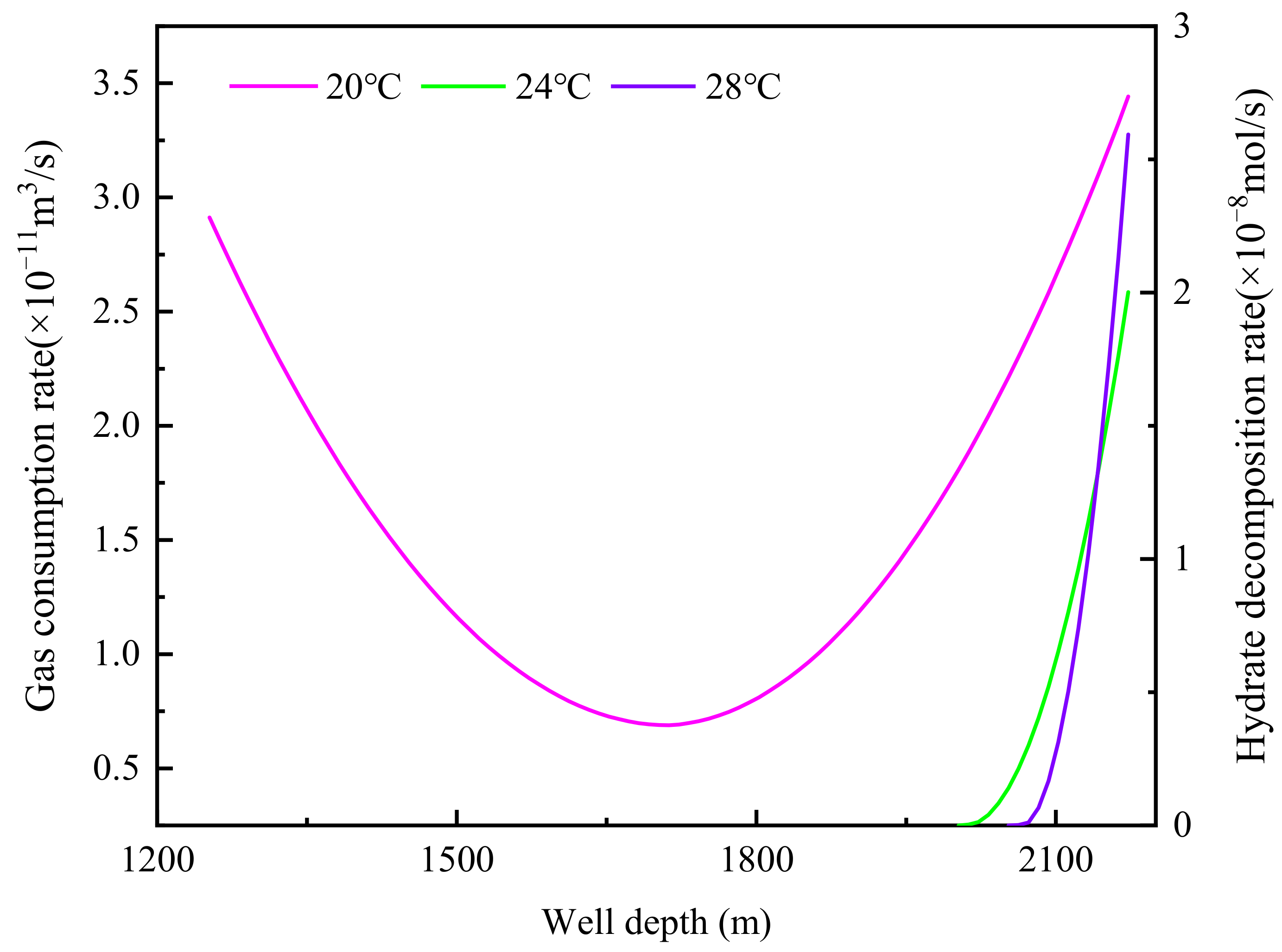
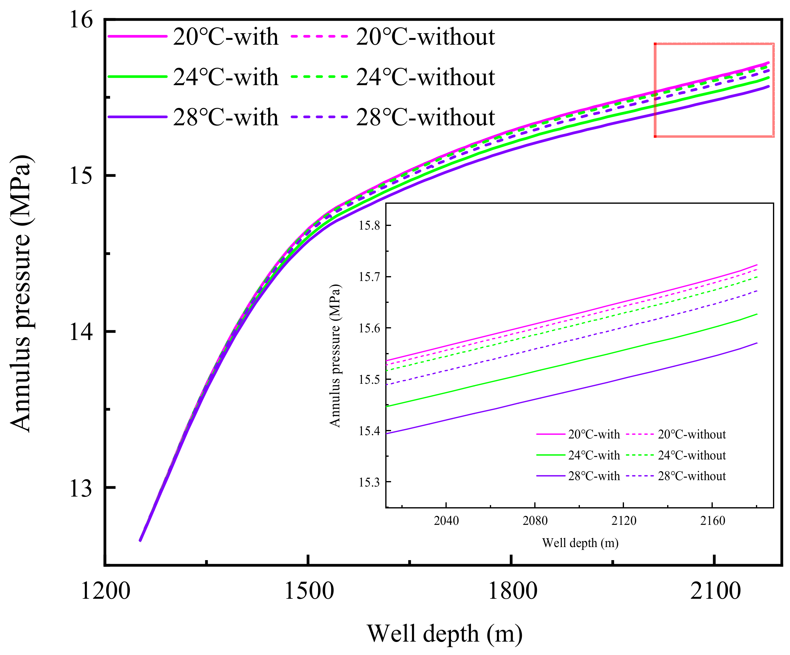
The variation curve of the annulus temperature with the well depth under different drilling fluid inlet temperatures is shown in Figure 4. When the inlet temperature of the drilling fluid is 20 °C, the annulus temperature is lower than the hydrate phase equilibrium temperature. Hydrate cuttings migrate in the original phase state, and a small amount of free gas from the three-phase layer transforms into hydrate in the annulus. As shown in Figure 5, when the inlet temperature of the drilling fluid is 20 °C, the annulus gas consumption rate is about 6.89 × 10⁻¹²~3.44 × 10⁻¹¹ m3/s. Combined with the annulus temperature and pressure curves in Figure 4 and Figure 6, when the inlet temperature of the drilling fluid is 20 °C, the hydrate generation effect only increases the return temperature of the drilling fluid by about 0.07 °C, and the bottom hole pressure increment is less than 0.01 MPa. The calculation results show that the generation rate of hydrate is very low when riserless drilling in a hydrate reservoir, and the influence of annulus hydrate generation on annulus temperature and pressure can be ignored. When the inlet temperature of the drilling fluid is 24 °C and 28 °C, the annulus temperature is higher than the hydrate phase equilibrium temperature and the hydrate cuttings decompose. As shown in Figure 5, the peak decomposition rates when drilling to the bottom of the well are about 2.01 × 10⁻⁸ mol/s and 2.59 × 10⁻⁸ mol/s. At this time, the annulus hydrate decomposition rate gradually decreases from the bottom hole to the mud line direction, and the decomposition rate decreases to zero at about 170 m and 110 m away from the bottom hole. This is mainly because the decomposition area of hydrate cuttings decreases continuously during the process of migration and decomposition, and the hydrate existing in the cuttings completely decomposes after a certain distance of migration. The effect of hydrate cuttings decomposition on annulus temperature and pressure is more significant with the increase in the drilling fluid inlet temperature. When the inlet temperature is 28 °C, the return temperature drop of the drilling fluid caused by the decomposition of hydrate cuttings is about 0.34 °C, and the bottom hole pressure drop is about 0.105 MPa. Therefore, when the inlet temperature of drilling fluid is relatively high, it is more beneficial to accurately predict annulus temperature and pressure by considering the influence of the decomposition of hydrate cuttings.

4.3. Influence of Drilling Fluid Displacement

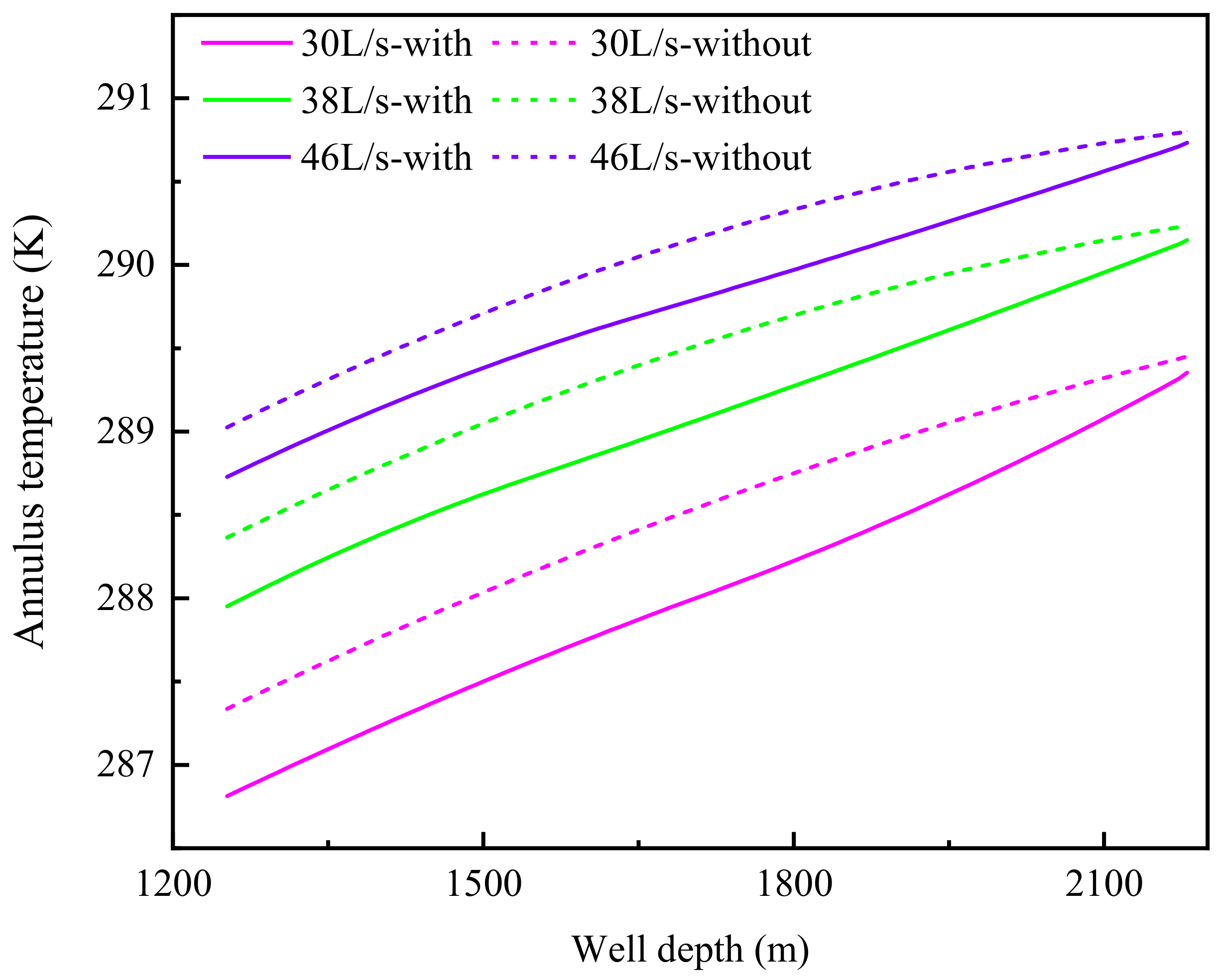
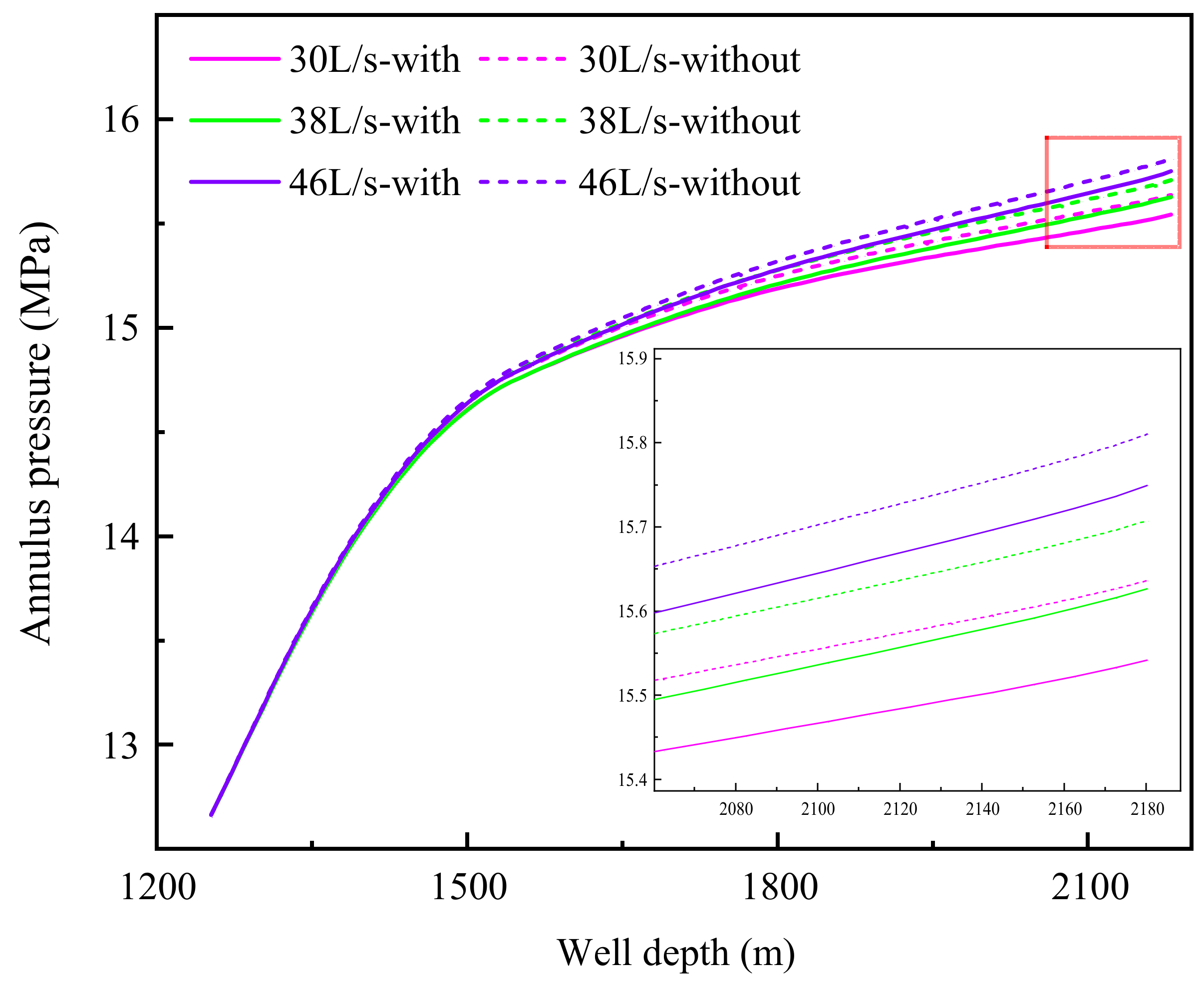
Figure 7 and Figure 8 show the annulus temperature and pressure curves of riserless horizontal well drilling in the hydrate reservoir under different drilling fluid displacement. With the increase in drilling fluid displacement, the heat transfer time between the fluid in the drill pipe and seawater decreases, and the bottom hole temperature increases, while the annular pressure loss increases significantly with the increase in displacement, and the bottom hole pressure increases accordingly. When the displacement of drilling fluid is 30 L/s and 46 L/s, the bottom hole temperature is 289.35 °C and 290.73 °C, respectively, and the bottom hole pressure is 15.542 MPa and 15.749 MPa, respectively, considering the decomposition of hydrate cuttings. When comparing the annulus temperature and pressure curves under different drilling fluid displacement, it is found that the influence of hydrate cuttings decomposition on annulus temperature and pressure decreases gradually with the increase in displacement. When the drilling fluid displacement is 30 L/s and 46 L/s, the return temperature drop of drilling fluid caused by hydrate cuttings decomposition is 0.53 °C and 0.31 °C, respectively, and the bottom hole pressure drop is 0.095 MPa and 0.060 MPa, respectively. This is mainly due to the slow return rate of drilling fluid when the displacement of drilling fluid is low. The volume fraction of hydrate cuttings in the annulus increases, and the decomposition time of hydrate cuttings is prolonged. Therefore, considering the influence of hydrate cuttings decomposition under lower drilling fluid displacement is more conducive to the accurate prediction of the temperature and pressure of riserless drilling in hydrate reservoirs.

4.4. Influence of Drilling Fluid Density

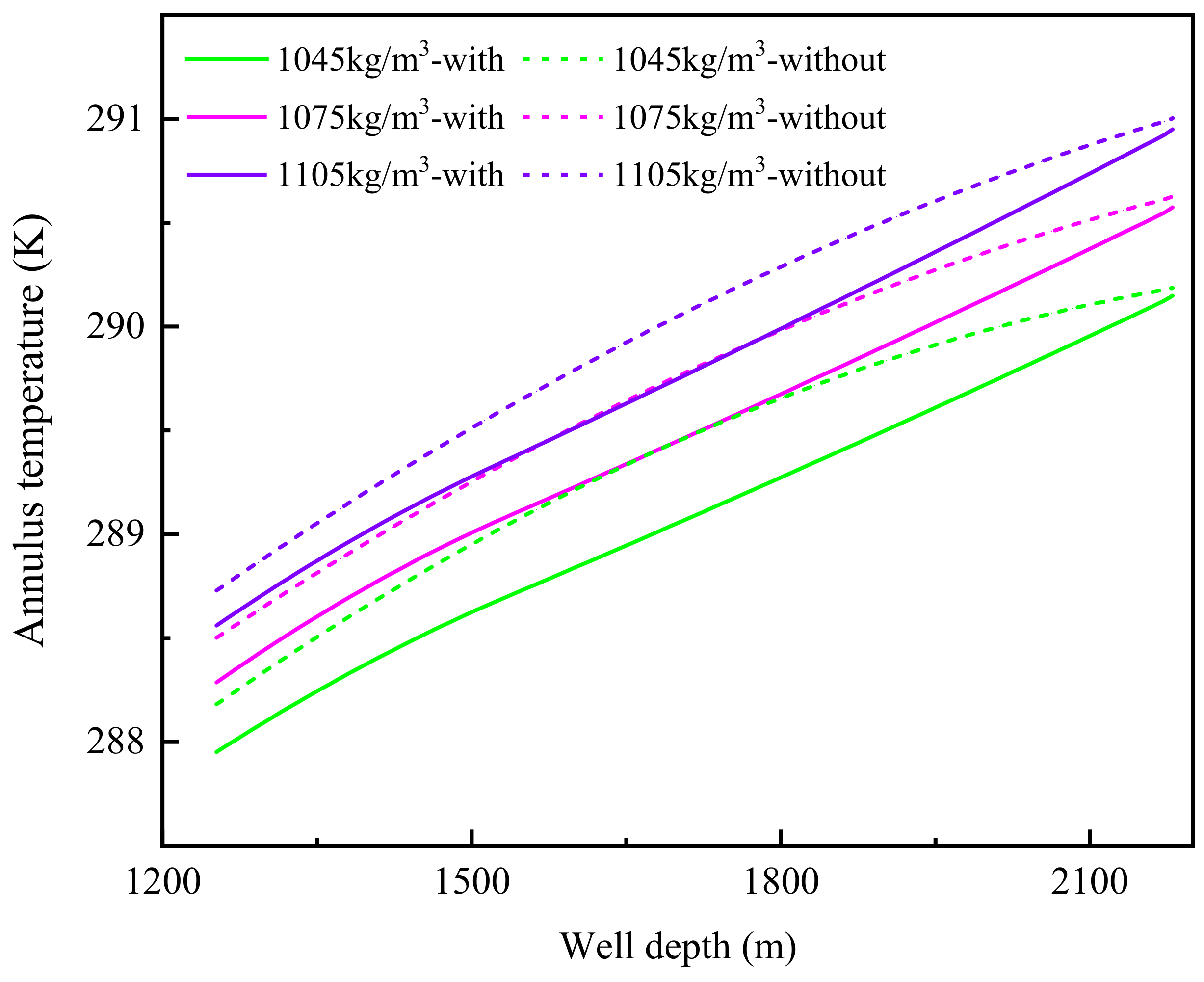
Figure 9 and Figure 10 show the variation curves of the annulus temperature and pressure with the well depth under different drilling fluid densities. With the increase in drilling fluid density, the bottom hole temperature and pressure increase slightly. Compared to the drilling fluid density of 1045 kg/m3, the bottom hole temperature and pressure increase by 0.41 °C and 0.082 MPa, respectively, when the drilling fluid density is 1075 kg/m3. The increase in the bottom hole temperature is due to the fact that the drilling fluid of the same temperature has more heat content with a higher density, and the temperature drop is smaller under the same heat loss. When the density of the drilling fluid increases by 30 kg/m3, the equivalent density of the bottom hole pressure only increases by 5.5 kg/m3, which is mainly due to the double gradient effect of riserless drilling. The increase in drilling fluid density is mainly applied to the short annulus section below the mud line, while the longer section above the mud line is the seawater hydrostatic column pressure. By comparing the annulus temperature and pressure curve with or without considering the decomposition of hydrate cuttings, the influence of hydrate cuttings decomposition on the annulus temperature gradually decreases with the increase in drilling fluid density. The influence of hydrate cuttings decomposition on annulus pressure varies slightly under different drilling fluid densities. When the drilling fluid densities are 1045 kg/m3, 1075 kg/m3, and 1105 kg/m3 respectively, the bottom hole pressure differences caused by hydrate cuttings decomposition are all about 0.071 MPa.

4.5. Influence of Penetration Rate

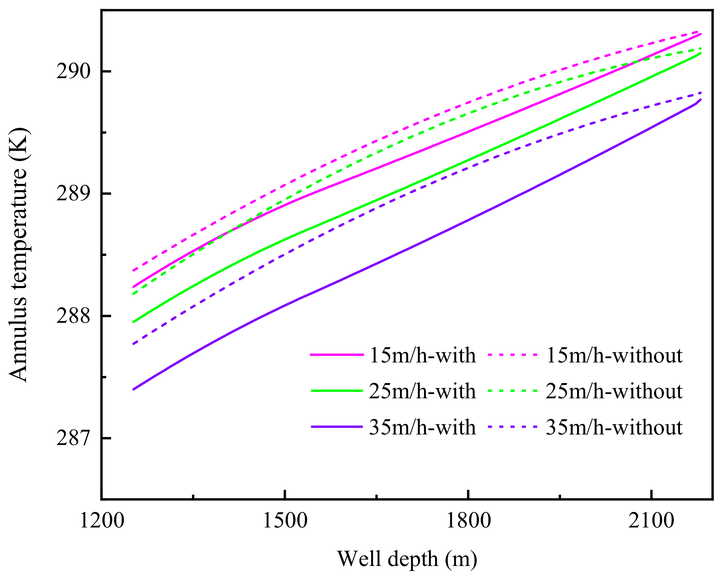
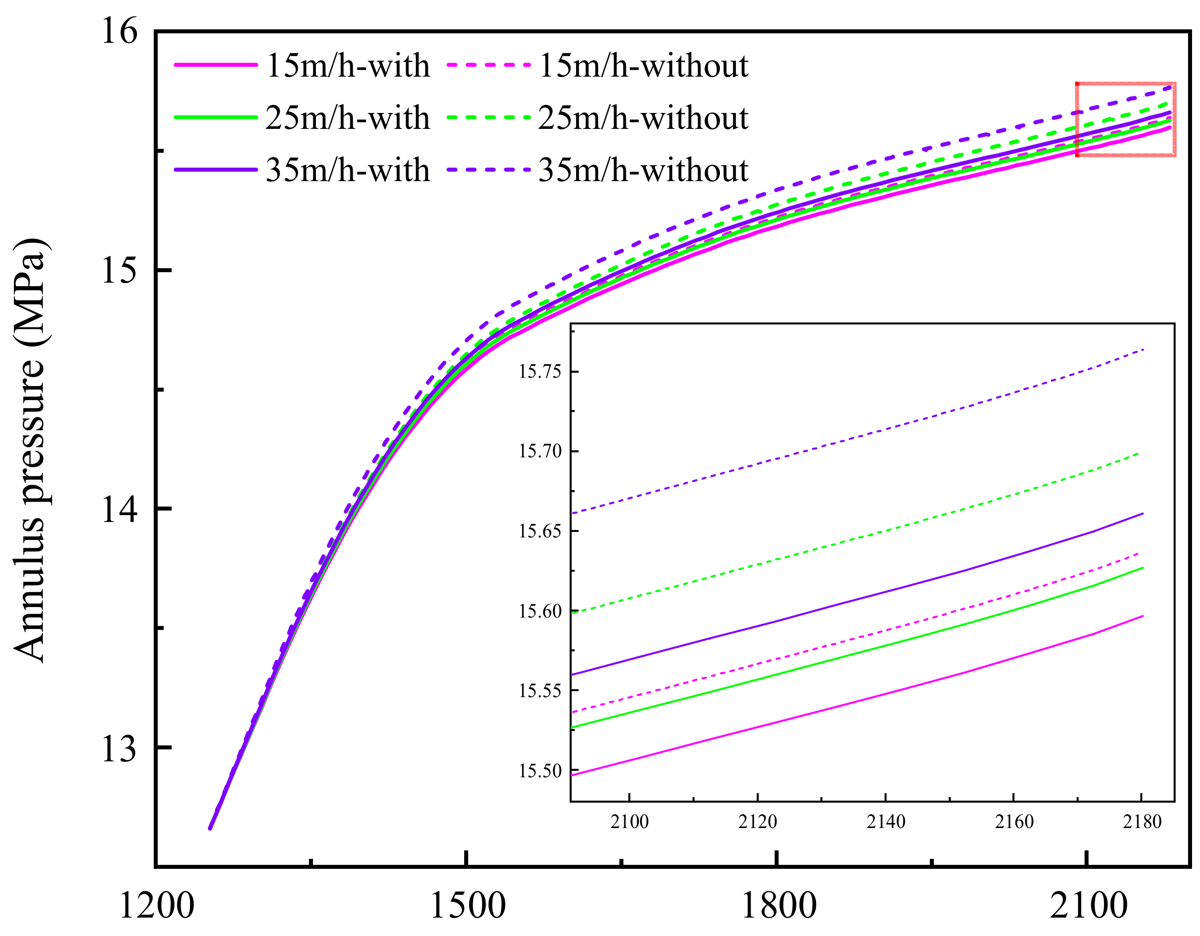
The variation curves of the annulus temperature with the well depth under different penetration rates are shown in Figure 11. The bottom hole temperature decreases with the increase in the ROP (rate of penetration). Considering the decomposition of hydrate cuttings, the bottom hole temperature is 290.31 °C when the ROP is 15 m/h, while the bottom hole temperature is 290.15 °C and 289.78 °C when the ROP is 25 m/h and 35 m/h, respectively. This is mainly because the circulating drilling time decreases with the increase in the ROP, and the wellbore temperature also decreases. In addition, with the increase in the ROP, the effect of hydrate cuttings decomposition on the annulus temperature gradually appears. When the ROP is 15 m/h, the decomposition of hydrate cuttings reduces the return temperature of the annulus drilling fluid by about 0.14 °C, while when the ROP is 25 m/h and 35 m/h, the return temperature of the annulus drilling fluid decreases by about 0.23 °C and 0.37 °C, respectively. This is mainly due to the increase in the annulus hydrate cuttings volume fraction alongside the increase in the ROP. Figure 12 shows the variation curves of the annular pressure with the well depth under different penetration rates. The annular pressure changes little with the increase in the ROP. This is because the increase in the ROP mainly affects the bottom hole pressure through the change in the annulus drilling fluid density. However, due to the double gradient effect, the increase in the drilling fluid density only acts on the short annulus section below the mud line. Compared to the annulus pressure curve under the same penetration rate, the influence of hydrate cuttings decomposition on the annulus pressure gradually increases with the increase in the ROP, which is also caused by the increase in the volume fraction of hydrate cuttings in the annulus. The maximum bottom hole pressure drop caused by hydrate cuttings decomposition is about 0.101 MPa when the ROP is 35 m/h. The above calculation results show that the decomposition of hydrate cuttings under different penetration rates has a major impact on the annulus temperature during the riserless drilling of hydrate reservoirs, while the impact on the annulus pressure under high penetration rates is noteworthy.

5. Conclusions

In this study, the temperature and pressure prediction model for riserless drilling in deep water gas hydrate reservoirs is established considering influence factors such as the migration and decomposition of the annulus hydrate cuttings, interphase mass transfer, and phase transition heat. Based on the established model, the effects of drilling in different layers and different drilling parameters on the temperature and pressure field of the riserless horizontal well drilling in a hydrate reservoir are explored with or without the consideration of the annular phase transition factor. The main conclusions are as follows:
(1)
Compared to drilling the three-phase layer, the annulus temperature and pressure change caused by the decomposition of hydrate cuttings is more obvious when drilling the hydrate layer.
(2)
When the inlet temperature of the drilling fluid is 20 °C, the annulus phase transition is mainly hydrate generation by free gas. However, the generation rate is very low, and the influence on the annulus temperature and pressure can be ignored. When the inlet temperature of the drilling fluid is 24 °C and 28 °C, the annulus phase transition is mainly the decomposition of hydrate cuttings. The influence of hydrate cuttings decomposition on the annulus temperature and pressure increases significantly with the increase in inlet temperature.
(3)
The annulus temperature and pressure increase significantly with the increase in drilling fluid displacement, while the influence of hydrate cuttings decomposition on temperature and pressure decreases with the increase in displacement.
(4)
Due to the double gradient effect of riserless drilling, a small range of variation in the ROP and drilling fluid density have little impact on the annulus pressure but mainly on the annulus temperature. When drilling without a riser, the change in displacement has a significant impact on the annular pressure, and the inlet temperature of the drilling fluid has the smallest impact on the annular pressure, while the inlet temperature of the drilling fluid has the greatest impact on the annular temperature. The influence of hydrate cuttings decomposition on the annulus temperature and pressure increases with the increase in ROP.
When drilling in deep water hydrate formation, the variation range of the drilling fluid inlet temperature is usually determined by the sea surface temperature. The inlet temperature of drilling fluid in the South China Sea is usually 20–30 °C. Hydrate saturation mainly depends on reservoir properties, which is usually between 10% and 70%. The displacement of drilling fluid mainly depends on the cuttings carrying effect, which is usually 10% to 30% higher than the minimum cuttings carrying displacement. The ROP is usually between 10 and 40 m/h. How to reduce the impact of hydrate cuttings decomposition on the annulus temperature and pressure during drilling in reservoirs with a high hydrate saturation will be a research direction worth paying attention to in the future.
(5)
In normal drilling conditions, hydrate cuttings decomposition has little impact on the annulus temperature and pressure, but under the conditions of a high drilling fluid inlet temperature (above 28 °C in this study), high hydrate saturation (above 31% in this study), low drilling fluid displacement (less than 30 L/s in this study), and a high penetration rate (above 35 m/h in this study), it is necessary to consider the impact of hydrate cuttings decomposition on annulus temperature and pressure.
It is worth noting that when drilling in deep-water hydrate formation without a riser, if there is too much methane gas generated by hydrate decomposition in the annulus, it is necessary to consider using an “unconventional natural gas collector” to reduce environmental pollution [35].
On the basis of this study, further research will be conducted on modeling and impact assessments of temperature and pressure fields during riser drilling in natural gas hydrate reservoirs as well as the migration and decomposition of hydrate cuttings.

Author Contributions

Methodology, F.Y.; software, X.N.; formal analysis, J.D.; investigation, J.H.; data curation, X.N.; writing—original draft preparation, F.Y.; writing—review and editing, Y.Z.; project administration, X.Z.; funding acquisition, Y.G. All authors have read and agreed to the published version of the manuscript.

Funding

The authors gratefully acknowledge the financial support of the National Key R&D Plan Project (2022YFC2806502), the National Natural Science Foundation of China (No. U21B2065, No. 52274022), the Basic Scientific Research Services of Central Universities (22CX01003A), the Postgraduate Innovation Funding Project (23CX04026A) and Key R&D Plan of Shandong Province (2022CXGC020407).

Data Availability Statement

The data used in this study are presented in the table in the manuscript.

Conflicts of Interest

The authors declare no conflict of interest.

References

  1. Wu, N.; Li, Y.; Chen, Q.; Liu, C.; Jin, Y.; Tan, M.; Dong, L.; Hu, G. Sand Production Management during Marine Natural Gas Hydrate Exploitation: Review and an Innovative Solution. Energy Fuels 2021, 35, 4617–4632. [Google Scholar]
  2. Li, Q.; Zhao, D.; Yin, J.; Zhou, X.; Li, Y.; Chi, P.; Han, Y.; Ansari, U.; Cheng, Y. Investigation on Sediment Instability Caused by Gas Production from Hydrate-Bearing Sediment in Northern South China Sea by Horizontal Wellbore: Evolution and Mechanism. Nat. Resour. Res. 2023, 32, 1595–1620. [Google Scholar] [CrossRef]
  3. Yin, F.; Gao, Y.; Chen, Y.; Sun, B.; Li, S.; Zhao, D. Numerical investigation on the long-term production behavior of horizontal well at the gas hydrate production site in South China Sea. Appl. Energy 2022, 311, 118603. [Google Scholar]
  4. Bosikov, I.I.; Martyushev, N.V.; Klyuev, R.V.; Savchenko, I.A.; Kukartsev, V.V.; Kukartsev, V.A.; Tynchenko, Y.A. Modeling and Complex Analysis of the Topology Parameters of Ventilation Networks When Ensuring Fire Safety While Developing Coal and Gas Deposits. Fire 2023, 6, 95. [Google Scholar] [CrossRef]
  5. Sahu, C.; Kumar, R.; Sangwai, J. A Comprehensive Review on Exploration and Drilling Techniques for Natural Gas Hydrate Reservoirs. Energy Fuels 2020, 34, 11813–11839. [Google Scholar]
  6. Liu, J.; Li, X. Recent Advances on Natural Gas Hydrate Exploration and Development in the South China Sea. Energy Fuels 2021, 35, 7528–7552. [Google Scholar]
  7. Wei, N.; Zhao, J.; Liu, A.; Zhou, S.; Zhang, L.; Jiang, L. Evaluation of Physical Parameters and Construction of the Classification System of Natural Gas Hydrate in the Northern South China Sea. Energy Fuels 2021, 35, 7637–7645. [Google Scholar] [CrossRef]
  8. Yin, F.; Gao, Y.; Zhang, H.; Sun, B.; Chen, Y.; Gao, D.; Zhao, X. Comprehensive evaluation of gas production efficiency and reservoir stability of horizontal well with different depressurization methods in low permeability hydrate reservoir. Energy 2022, 239, 122422. [Google Scholar]
  9. Wang, B.; Fan, Z.; Wang, P.; Liu, Y.; Zhao, J.; Song, Y. Analysis of depressurization mode on gas recovery from methane hydrate deposits and the concomitant ice generation. Appl. Energy 2018, 227, 624–633. [Google Scholar]
  10. Wang, Y.; Feng, J.; Li, X. Pilot-scale experimental test on gas production from methane hydrate decomposition using depressurization assisted with heat stimulation below quadruple point. Int. J. Heat Mass Transf. 2019, 131, 965–972. [Google Scholar]
  11. Yuan, Q.; Sun, C.; Yang, X.; Ma, P.; Ma, Z.; Liu, B.; Ma, Q.; Yang, L.; Chen, G. Recovery of methane from hydrate reservoir with gaseous carbon dioxide using a three-dimensional middle size reactor. Energy 2012, 40, 47–58. [Google Scholar] [CrossRef]
  12. Zhao, J.; Liu, Y.; Guo, X.; Wei, R.; Yu, T.; Xu, L.; Sun, L.; Yang, L. Gas production behavior from hydrate-bearing fine natural sediments through optimized step-wise depressurization. Appl. Energy 2020, 260, 114275. [Google Scholar]
  13. Khasanov, M.K.; Stolpovsky, M.V.; Gimaltdinov, I.K. Mathematical model for carbon dioxide injection into porous medium saturated with methane and gas hydrate. Int. J. Heat Mass Transf. 2018, 127, 21–28. [Google Scholar] [CrossRef]
  14. Ye, J.; Qin, X.; Xie, W.; Lu, H.; Ma, B.; Qiu, H.; Liang, J.; Lu, J.; Kuang, Z.; Lu, C.; et al. Main progress of the second gas hydrate trial production in the South China Sea. Geol. China 2020, 47, 557–568. [Google Scholar]
  15. Merey, S. Evaluation of drilling parameters in gas hydrate exploration wells. J. Pet. Sci. Eng. 2018, 172, 855–877. [Google Scholar]
  16. Li, Q.; Zhang, C.; Yang, Y.; Ansari, U.; Han, Y.; Li, X.; Cheng, Y. Preliminary experimental investigation on long-term fracture conductivity for evaluating the feasibility and efficiency of fracturing operation in offshore hydrate-bearing sediments. Ocean Eng. 2023, 281, 114949. [Google Scholar]
  17. Malozyomov, B.V.; Martyushev, N.V.; Kukartsev, V.V.; Tynchenko, V.S.; Bukhtoyarov, V.V.; Wu, X.; Tyncheko, Y.A.; Kukartsev, V.A. Overview of Methods for Enhanced Oil Recovery from Conventional and Unconventional Reservoirs. Energies 2023, 16, 4907. [Google Scholar]
  18. Peng, Q.; Fan, H.; Ji, R.; Lai, M.; Zhou, H.; Liu, J.; Fu, S. Analysis of Circulating Pressure Drop in Surface Formation Wellbore in Riserless Drilling. China Pet. Mach. 2015, 43, 73–77. [Google Scholar]
  19. Jiang, W.; Fan, H.; Ji, R.; Liu, Y. Calculation Model of Equivalent Circulation Density in Riserless Drilling. China Pet. Mach. 2019, 47, 61–66. [Google Scholar]
  20. Gao, Y.; Sun, B.; Xu, B.; Wu, X.; Chen, Y.; Zhao, X.; Chen, L. A Wellbore-Formation-Coupled Heat-Transfer Model in Deepwater Drilling and Its Application in the Prediction of Hydrate-Reservoir Dissociation. SPE J. 2017, 22, 756–766. [Google Scholar] [CrossRef]
  21. Gao, Y.; Ye, C.; Zhao, X.; Wang, Z.; Li, H.; Sun, B. Risk analysis on the blowout in deepwater drilling when encountering hydrate-bearing reservoir. Ocean Eng. 2018, 170, 1–5. [Google Scholar] [CrossRef]
  22. Mao, L.; Cai, M.; Liu, Q.; Wang, G. Dynamical Simulation of High-Pressure Gas Kick in Ultra-Deepwater Riserless Drilling. J. Energy Resour. Technol. 2021, 143, 063001. [Google Scholar] [CrossRef]
  23. Choe, J. Analysis of Riserless Drilling and Well-Control Hydraulics. SPE Drill Complet. 1999, 14, 71–81. [Google Scholar] [CrossRef]
  24. Sun, J.; Ning, F.; Lei, H.; Gai, X.; Sánchez, M.; Lu, J.; Li, Y.; Liu, L.; Liu, C.; Wu, N.; et al. Wellbore stability analysis during drilling through marine gas hydrate-bearing sediments in Shenhu area: A case study. J. Pet. Sci. Eng. 2018, 170, 345–367. [Google Scholar] [CrossRef]
  25. Sun, J.; Ning, F.; Liu, T.; Li, Y.; Lei, H.; Zhang, L.; Cheng, W.; Wang, R.; Cao, X.; Jiang, G. Numerical analysis of horizontal wellbore state during drilling at the first offshore hydrate production test site in Shenhu area of the South China Sea. Ocean Eng. 2021, 238, 109614. [Google Scholar] [CrossRef]
  26. Cheng, W.; Ning, F.; Sun, J.; Liu, Z.; Jiang, G.; Li, X. A porothermoelastic wellbore stability model for riserless drilling through gas hydrate-bearing sediments in the Shenhu area of the South China Sea. J. Nat. Gas Sci. Eng. 2019, 72, 103036. [Google Scholar] [CrossRef]
  27. Gelet, G.; Loret, B.; Khalili, N. Borehole stability analysis in a thermoporoelastic dual-porosity medium. Int. J. Rock Mech. Min. Sci. 2012, 50, 65–76. [Google Scholar] [CrossRef] [Green Version]
  28. Liao, Y.; Wang, Z.; Chao, M.; Sun, X.; Wang, J.; Zhou, B.; Sun, B. Coupled wellbore-reservoir heat and mass transfer model for horizontal drilling through hydrate reservoir and application in wellbore stability analysis. J. Nat. Gas Sci. Eng. 2021, 95, 104216. [Google Scholar] [CrossRef]
  29. Liao, Y.; Sun, X.; Sun, B.; Gao, Y.; Wang, Z. Transient gas-liquid-solid flow model with heat and mass transfer for hydrate reservoir drilling. Int. J. Heat Mass Transf. 2019, 141, 476–486. [Google Scholar] [CrossRef]
  30. Dong, S.; Wang, Z.; Cao, F. Wellbore Temperature Calculation Model for Horizontal Wells in Shallow Hydrate Reservoirs in Deep Water. Spec. Oil Gas Reserv. 2020, 27, 157–161. [Google Scholar]
  31. Chuai, S.; Wang, H.; Zhang, N. 3-D Phase Equilibrium Surface Equation of Methane Hydrate Considering the Effect of Temperature, Pressure and Salt Concentration. Chem. Eng. Oil Gas 2019, 48, 49–55. [Google Scholar]
  32. Kim, H.C.; Bishnoi, P.R.; Heidemann, R.A.; Rizvi, S.S.H. Kinetics of methane hydrate decomposition. Chem. Eng. Sci. 1987, 42, 1645–1653. [Google Scholar] [CrossRef]
  33. Mohammadzadeh, K.; Hashemabadi, S.H.; Akbari, S. CFD simulation of viscosity modifier effect on cutting transport by oil based drilling fluid in wellbore. J. Nat. Gas Sci. Eng. 2016, 29, 355–364. [Google Scholar] [CrossRef]
  34. Fu, J.; Su, Y.; Jiang, W.; Xiang, X.; Li, B. Multiphase flow behavior in deep water drilling: The influence of gas hydrate. Energy Sci. Eng. 2020, 8, 1386–1403. [Google Scholar] [CrossRef] [Green Version]
  35. Malozyomov, B.V.; Golik, V.I.; Brigida, V.; Kukartsev, V.V.; Tynchenko, Y.A.; Boyko, A.A.; Tynchenko, S.V. Substantiation of Drilling Parameters for Undermined Drainage Boreholes for Increasing Methane Production from Unconventional Coal-Gas Collectors. Energies 2023, 16, 4276. [Google Scholar] [CrossRef]
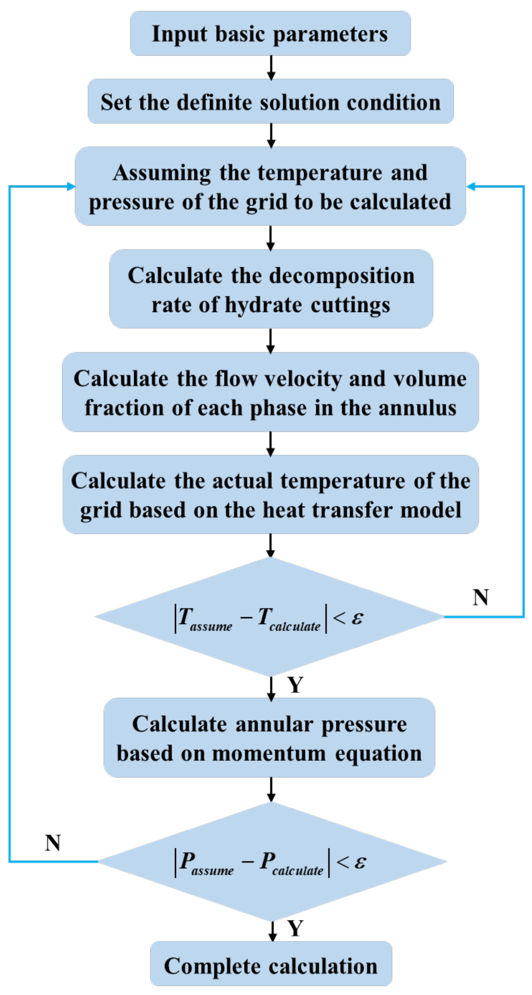
Figure 1. Solution flow of the temperature and pressure field for riserless drilling in hydrate reservoirs.
Energies 16 05903 g001
Figure 2. Annular temperature distribution with drilling time.
Energies 16 05903 g002
Figure 3. Annular pressure comparison of drilling a hydrate layer and a three-phase layer.
Energies 16 05903 g003
Figure 4. Annulus temperature curves at different drilling fluid inlet temperatures.
Energies 16 05903 g004
Figure 5. Variation curves of annular hydrate phase transition rates with well depth under different drilling fluid inlet temperatures at completion of drilling.
Energies 16 05903 g005
Figure 6. Annulus pressure curves at different drilling fluid inlet temperatures.
Energies 16 05903 g006
Figure 7. Annulus temperature curves under different drilling fluid displacement.
Energies 16 05903 g007
Figure 8. Annulus pressure curves under different drilling fluid displacement.
Energies 16 05903 g008
Figure 9. Annulus temperature curves under different drilling fluid densities.
Energies 16 05903 g009
Figure 10. Annulus pressure curves under different drilling fluid densities.
Energies 16 05903 g010
Figure 11. Annulus temperature curves under different penetration rates.
Energies 16 05903 g011
Figure 12. Annulus pressure curves under different penetration rates.
Energies 16 05903 g012
Table 1. Relevant parameters used for calculation and analysis.
ParameterValueParameterValue
Mudline temperature, °C3.6Rate of penetration, m25
Geothermal gradient, °C·m−10.047Hydrate density, kg·m−3910
Drilling fluid density, kg·m−31045Salinity of drilling fluid, %5.0
Drilling fluid displacement, L·min2280Formation thermal conductivity, W·m−1·°C−12.25
Drilling fluid inlet temperature, °C24Thermal conductivity of drill pipe, W·m−1·°C−143.75
Initial viscosity of drilling fluid, mPa·s12Thermal conductivity of drilling fluid, W·m−1·°C−10.60
Hydrate saturation of hydrate layer, %31.0Specific heat capacity of drilling fluid, J·kg−1·°C−13930
Hydrate saturation of three-phase layer, %11.7Phase equilibrium translation coefficient24.0
Gas saturation of three-phase layer, %13.2Average diameter of
cuttings, mm
8
Inside diameter of drill
collar, m
0.073Inside diameter of drill pipe, m0.121
Outside diameter of drill
collar, m
0.165Outside diameter of drill pipe, m0.139
Disclaimer/Publisher’s Note: The statements, opinions and data contained in all publications are solely those of the individual author(s) and contributor(s) and not of MDPI and/or the editor(s). MDPI and/or the editor(s) disclaim responsibility for any injury to people or property resulting from any ideas, methods, instructions or products referred to in the content.