Abstract
The development of power electronics, including high-efficiency power supply systems, changes the structure of perception of the types of electrical energy receivers connected to the power grid at each supply voltage level. In the past, the dominant type of receivers were constant impedance devices. Currently, more and more devices have power supplies, which are most often constant power receivers. The construction and technological diversity of receivers allows mixed receivers, which are a combination of constant power and constant impedance receivers, to be distinguished. Therefore, there is a need to determine the impact of the type of electrical energy receivers on the power grid, both in the context of the operation of a single receiver and in the case of a branched power grid with a high penetration of distributed generation. This article will discuss the impact of the type of electrical energy receivers on the operation of the power grid, with particular emphasis on the issue of electrical energy losses at changing voltages. To determine the impact of receivers, simulation studies were performed based on two case stages: the first is a fragment of a low-voltage power grid in a household that supplies a heating device, which is analyzed as a different type of receiver; the second is a fragment of a low-voltage power grid with various types of consumers and photovoltaic installations. The research was carried out on the basis of the mathematical model of the low-voltage power network developed by the authors using the electric multipole method and Newton’s method. The obtained results show that the type of receiver may have an impact on electrical energy losses.
1. Introduction
The problem of electrical energy losses in power grids has existed since the beginning of electricity use and results from physical phenomena occurring in devices and elements that make up the power system. There are two basic types of receivers: constant impedance and constant power. Currently, energy losses are also significantly influenced by the increase in the share of electricity production from renewable energy sources and the location of generation units in the grid.
In low-voltage power grids, there are three main causes of voltage changes:
- The switching processes of receivers (transient states);
- Voltage regulation in the MV power grid;
- The connection of distributed generation (both in MV and LV power grid).
In many different publications [1,2,3,4,5,6,7,8,9,10,11,12,13,14,15,16,17,18,19,20,21,22,23,24,25,26,27,28,29,30], the authors deal with the analysis of power losses in power grids, at each voltage level, in various configurations of the power grid operation.
The author in [1] presents the results of calculations of the impact of the connection point and the size of the source on power and energy losses in the medium voltage power distribution network, focusing mainly on the analysis of power losses. However, the influence of changes in the supply voltage on the tested part of the network and the type of receiver were not taken into account, assuming a certain, constant value of the load.
In turn, in [2], the author analyzes active power losses in a low-voltage power grid with distributed generation and on-load voltage regulation, assuming the symmetry of phase loads. In this case, only constant impedance receivers were considered.
The authors of [3] investigate the impact of the level of distributed generation (DG) penetration on power losses and the voltage profile of radial distribution networks (RDN). In order to determine the impact of distributed generation on power losses and the voltage profile, the load on the substation rails was gradually increased. To evaluate the results, a new voltage stability index (NVSI) and active and reactive power voltage indexes (EPVSI and EQSVI) were proposed. The simulation tests performed in MATLAB showed that, with the level of DG penetration, the active and reactive power losses form a square curve with a minimum, and the losses are reduced at low penetration levels. After exceeding a certain level of DG penetration, power losses start to increase.
The authors in [4] also dealt with the influence of distributed generation (asynchronous, synchronous, and induction generators) on power losses and the voltage profile in the sub-transmission network, proposing various approaches and indicators, including the so-called global performance index. The authors concluded that DG technologies generally reduce power losses; however, they differ depending on the type of DG technology.
In [5], the authors also studied the impact of distributed generation on the operation of HV and MV distribution networks. In the case of MV networks, they considered various cases of source location, taking into account the network. In the case of the HV network, the authors analyzed the issues related to the impact of the source operation on the voltage levels in the vicinity of the connection point, losses, and active and reactive power flows between the LV and HV networks. The authors came to the conclusion that the location of distributed generation (wind power plants) significantly reduces power losses in the MV network, and these losses strongly depend on reactive power from wind generation. Changing the location of the source connection causes a change in the power flow in the lines and, consequently, a change in power losses. In the field of LV/HV grids, power losses strongly depend on the voltage regulation in LV/110 kV substations, and even small changes in wind generation between individual-system power plants strongly affect the load on the substation and the distribution of power and power losses.
Issues related to the minimization of power losses are often associated with the use of optimization methods and issues, which are described in detail in the review provided in [6]. In many papers [7,8,9,10,11,12,13,14,15,16,17,18,19], researchers use various optimization methods, in which one of the objective functions is reducing power losses.
The authors in [7] dealt with the optimal location of distributed generation and electric vehicle charging stations (EVCS) in the distribution network in order to reduce power losses and improve the voltage profile. Modeling with the use of the probability distribution function (PDF) was used to model changes related to distributed generation, and the location of sources and their power is determined by the voltage stability index (VSI) and the political optimization algorithm (POA), while the strategies for charging electric vehicles (EV) were considered using the conventional charging method (CCM) and the optimized charging method (OCM).
The authors of [8,9,10,11] dealt with the minimization of power losses and the improvement of the voltage stability factor (VSI) in the distribution network by network reconfiguration and DR deployment. In [9], optimization was performed using the innovative adaptive shuffled frogs leaping algorithm (ASFLA). Similar issues were considered by the authors of [10], who used a hybrid optimization algorithm (a combination of the generic algorithm (GA) and the improved particle floating optimization algorithm) to minimize power losses and improve the voltage profile by system reconfiguration, the DG location, and swarm optimization (IPSO). Meanwhile, in [11], to solve the same problems, the authors used a hybrid algorithm based on the metaheuristics of the gray wolf optimizer (GWO) and the particle swarm optimizer (PSO) algorithms.
In [12], the peafowl optimization algorithm (POA) was used, in which as many as five objective functions were defined, including the minimization of active power losses. In [13], the gray wolf optimization algorithm (GWO) was used to reduce active power losses. The authors state that the use of GWO to control the network operation, depending on the configuration, can reduce power losses by 12% to 65.5%.
The authors in [14] researched the optimal location and size of the PV installation in order to reduce active power losses with high PV penetration and the improvement of the voltage profile simultaneously. To achieve the assumed goals, they used the modified JAYA algorithm, which they tested on the IEEE-33 bus test system in the MATPOWER and OCTAVE programs. The applied method allowed for a 56.9% reduction in power losses and an improvement of voltages within the permissible limits in all busbars.
The optimal location of the distributed generation in the distribution system, taking into account the variability of the active power load in the context of minimizing active power losses and improving the voltage profile, was also researched by the authors in [15], in which a method involving the optimal allocation of DG units in a radial network was proposed.
In order to reduce power losses and increase the level of DG penetration in radial distribution networks, the authors of [16] used hybrid optimization consisting of an analytical approach and particle swarm optimization (PSO). In each of the analyzed cases, the power losses were reduced by over 80%, while the DG penetration was also increased by over 80% in each of the variants. The authors of [17] dealt with a similar issue using the particle swarm optimization algorithm (PSO) and differential evolution (DE). The results indicate that the DE algorithm effectively reduces power losses and improves the voltage profile. The particle swarm optimization algorithm for reducing power losses using a static synchronous compensator (STATCOM) was studied in [18]. In turn, in [19], the authors used the improved ant colony optimization (ACO) algorithm for optimal power flow and the minimization of power losses in power grids due to the fact that the analyzed problem was non-linear, non-convex, complex, and strongly limited.
Other solutions related to the use of various optimization algorithms to reduce power losses in power grids include the following:
- Calculation method optimization and the self-organizing migration algorithm (SOMA) [20];
- The power flow allocation algorithm (PFA) [21];
- Multi-criteria optimization methods (non-dominated sorting genetic algorithm II (NSGA-II), multiobjective particle swarm optimization (MPSO), and the biased random keys genetic algorithm (BRKGA) [22];
- The Pathfinder algorithm (PFA) [23];
- The stochastic fractal search optimization algorithm (SFSOA) [24].
To analyze power losses in power grids with wind generation, the authors of [25] used the Weibull distribution.
The increase in the number of photovoltaic installations in distribution grids prompted the authors of [26] to research the reduction in power losses in the medium voltage distribution grid by means of photovoltaic inverters. The authors found that an increase in the total system load increases system savings when reactive power is generated by PV inverters (in the case of high power factor operation) and that losses are then reduced.
In [27], the authors studied the impact of the number of photovoltaic panels on power losses in the distribution network and the voltage profile. Assuming a constant value of the supply voltage, the number of photovoltaic panels was increased. On the basis of simulation studies in MATLAB, it was found that a larger number of panels improves the voltage profile and reduces power losses, but there is a certain limit at which an increase in the number of panels causes an increase in power losses.
In order to reduce losses, e.g., in island microgrids that operate independently of the main grid, the authors of [28] propose real-time primary control based on optimized statism coefficients. The model is controlled online using an acquisition, communication, and human–machine interface (HMI) system. The implementation of the objective function (the minimization of system power losses) was solved based on glowworm swarm optimization (GSO). Tests carried out on three test systems based on hardware-in-the-loop (HIL) indicate benefits in terms of reducing power losses: operational losses were reduced by 16.15% compared to the base variant.
The issue of active power losses in the distribution network was examined in terms of the impact of electrical energy quality indicators in [29]. Based on the test model of the 22 kV distribution network, the authors examined the impact of changes in power factor (PF), load asymmetry, and higher current harmonics in the context of minimizing active power losses. To reduce losses, it was proposed to distribute the load evenly and to use compensating devices and passive and active filters.
In [30], the author discusses issues related to the management of the operation of a low-voltage power microsystem due to the development of power distribution networks (smart grids), mainly in the context of power losses, although he also raises the issue of energy losses. According to the author, from the global point of view, the optimization of power losses will not always bring the expected results in terms of energy losses. He also adds that the work and demand for power cannot be predicted in principle, so minimizing power losses turns out to be a rational solution, bearing in mind that the transparency of the rules applied in financial settlements is the most important thing anyway.
Based on the analysis of the literature on the subject, the authors state that there are few works in which researchers would deal with, firstly, electrical energy losses, which is the most important issue from the recipient’s point of view, and, secondly, the type of receiver and its correlation with the aforementioned electrical energy losses with changing supply voltages.
Currently, there is no one type of receiver, and it is necessary to pay attention to how the given receivers affect the network with the change of the supply voltage—in the case of constant impedance receivers, a higher voltage causes a greater current flow (Z = const) and consequently higher power consumption, and in the case of constant power receivers, a higher voltage value causes a smaller current flow because P = const. However, and most often in installations and networks, these are receivers of various types, so you should also take into account the aspects of combining both groups of receivers and know the effects of their impact on the network in terms of power losses and, consequently, energy losses. Table 1 below presents a list of the most frequently used electrical devices in households with three proposed types of receivers.

Table 1.
List of electrical devices most often used in households, broken down by receiver type.
Table 1.
List of electrical devices most often used in households, broken down by receiver type.
| Type of Receiver | Examples of Electric Devices |
|---|---|
| Constant impedance receiver Z = const | Electric kettle, oven, washing machine, dryer, incandescent light sources, and vacuum cleaner |
| Constant power receiver P = const | Induction cooker, LED light sources, computer, laptop, TV, monitor, and |
| Mixed receiver | heat pumps |
On the basis of the above issues, there are several questions involving topics related to electrical energy losses: What impact does the type of receiver have on electrical energy losses? What is the impact of changing the mains voltage on electrical energy losses?
In the era of energy transformation, about which more can be found in [31], research was undertaken to examine the impact of the type of electrical energy receivers on electrical energy losses in the power grid at different voltages supplying these receivers.
This article consists of four chapters. This first chapter contains an introduction to the subject of the work, a review of the literature, a justification for addressing the issue in the work, relevant questions, and the purpose and scope of the work.
The second chapter deals with the materials and methods of analysis. Issues related to the mathematical modeling of the types of receivers present in power grids with the use of the electric multipole method based on RL, ERL, J, and JRL branches are described here. The basics of solving the model using Newton’s algorithm are also presented here. In addition, this chapter presents a description of the research methodology, the purpose of the research, the research objects, a description and diagrams of the tested systems, and a description of the simulated work variants. The third chapter contains the obtained results and their discussion. The last chapter is a summary.
2. Materials and Methods
The authors performed simulation experiments in order to answer the following questions: what influence does the type of receiver have on energy losses, and what is the impact of changing the mains voltage on energy losses? However, before proceeding with the selection of the simulation environment, the requirements for the software were defined, which should enable, among other things, the modeling of constant power, constant impedance, and mixed receivers; the possibility of asymmetric operation (a different load in each phase of the receiver); and the implementation of load profiles and generation from renewable energy source (RES) installations.
In order to meet these requirements, the authors decided to use a mathematical modeling method based on a combination of the electric multipole method with Newton’s method.
Figure 1 shows the modeled system in the form of electrically connected n multipoles (ESn structural elements).
The proposed method of mathematical description is described in [32,33,34,35]. It consists of determining the correction vector , which will enable the determination of the physical quantities sought in the i-th iteration (e.g., the vector of the external potentials of each multipole and the vector of the currents of the external branches ). Therefore, each structural element can be described using Kirchhoff’s laws and Newton’s method. The so-called outer multipolar equation is
where —square matrix of size ξ × ξ in the i-th iteration; —ξ-element column matrix in the i-th iteration; —approximation of the potential vector of external nodes of the ES element; —approximation of the current vector of the external branches of the ES element.

Figure 1.
Diagram of the electrical system as a multipole connection [33].
Analyzing the scheme of the system shown in Figure 1, it can be observed that the outer branches of each multipole connect at ξ + 1 nodes of the analyzed system. It can be seen that one of the nodes has a potential equal to zero, so, for the remaining nodes, we can write a vector of approximations of the potentials of the system:
Obtaining the above approximation vector and using the incident matrix , one can determine the mathematical relationship with the approximation vector of the external node potentials of a given ES element :
Details on the definition of the incidence matrix can be found in [32,33,34,35].
For independent approximations of the nodes of the system, according to Kirchhoff’s first law, the following equation can be written:
Substituting Equations (1) and (3) into Dependence (4) and performing basic mathematical transformations, the equation of the approximation of potential nodes of the system is obtained:
where
The elements of the matrixes and are determined by the parameters associated with a given structural element (ES). The algorithm of the mathematical modeling of electrical systems with the method presented in the paper has been presented and discussed in [33].
The MATLAB R2022b program was selected as a simulation tool that enables the implementation of the above method. Before conducting the simulation experiment, simulation models of elements of a low-voltage power grid were first developed, including constant impedance, constant power, mixed load, real voltage sources, power line, and distributed generation. Mathematical models of individual elements of the power system are presented in [33].
Three types of models can be distinguished here: the ERL-type model, which can be used to simulate a real voltage source; the RL-type model, which can simulate constant impedance receivers or power lines; the J-type model, which can simulate constant power receivers (and power generation, e.g., by photovoltaic installations); and a JRL-type model, which can simulate mixed loads. Figure 2 shows the diagrams of the models used to create the tested power systems. In Figure 2, the numerals indicate the number of the multi-pole node, V1, V2, external potentials of the element, V12 - voltage (potential difference).


Figure 2.
Diagrams of the models used to create the tested power systems: (a) ERL-type branch model (real voltage source); (b) RL-type branch model (constant impedance receiver Z = const or power line); (c) J-type branch model (constant power load P = const or distributed generation); (d) JRL-type branch model (mixed receiver).
Each structural element (ES) in the diagrams (Figure 3, Figure 4, Figure 5, Figure 6 and Figure 7) has been represented by an appropriate mathematical model. First, tests were carried out to determine the impact of the type of receiver and changes in the supply voltage on the amount of electrical energy losses in low-voltage lines. In the first experiment, a fragment of a low-voltage power grid supplying one household receiver was taken into account. The electrical system consisted of three structural elements (ESk) and a number of independent nodes, i.e., ξ = 5. ES1 is an ERL-type model describing the power system, ES2 is an RL-type model describing the internal power line (YKY 5 × 10 mm2 with unit parameters rl = 1.83 Ω/km, xl = 0.107 Ω/km and an internal power supply line length of l = 60 m). ES3 is a receiver model—a heating device with a storage capacity of V = 120 dm3, in which water was heated from the initial temperature Tp = 20 °C to the final temperature Tk = 50 °C. The following parameters were adopted for the study:
- Specific heat of water cw = 4.1899 ;
- Water density ρw = 0.9982 ;
- Total efficiency ηc = 94.8%.
For the above parameters, a constant amount of energy was calculated that must be supplied to perform the heating process:
where mw—mass of water in kg; mw = V ∙ ρw; ΔT—temperature difference in K; ΔT = Tk—Tp.
A heating device with a rated power of 2000 W was considered first as a constant impedance receiver (such as an electric boiler or heater); second, as a constant power receiver (such as an induction water heater); and, in the third case, as a mixed load (constant power and constant impedance with different proportions of the share of constant power and constant impedance, but the total rated power was 2000 W). The experiment examined the impact of various types of receivers representing an electric boiler and changes in the supply voltage of a given type of receiver on energy losses. The scheme of the tested system is shown in Figure 3.
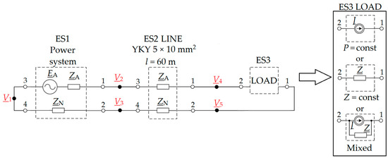
Figure 3.
Equivalent diagram of the tested power system for the first part of the experiment.
The second part of the simulation experiment was aimed at determining electrical energy losses in a fragment of a low-voltage rural power grid, depending on the type and nature of the receiver and the value of the supply voltage. Changes in the supply voltage may result from a large number of generation sources connected to the medium voltage grid. The tested part of the power grid is powered from an MV/LV transformer with a capacity of 250 kVA and a constant voltage ratio of 15.75/0.42 kV/kV, without on-load voltage regulation. In addition, the impact of distributed generation and its location in the tested part of the low-voltage network on electrical energy losses in power lines and transformers was analyzed. A fragment of the tested network with structural elements marked is shown in Figure 5, Figure 6 and Figure 7. These fragments were used to develop a mathematical model. A detailed procedure for creating mathematical models and an algorithm for solving equations using this method is presented in [33]. In the analyzed system, the following structural elements are distinguished: a real equivalent voltage source, consisting of an ideal voltage source and equivalent impedance, which consists of the impedance of the power system ZQ determined from the short-circuit power of 4.21 MVA for the voltage of 0.4 kV and the impedance of the ZT transformer; a working earthing resistance, which, in this analysis, is assumed to be 1.5 Ω or 5.5 Ω; power lines; loads; and distributed generation. The power line model consists of four branches. Each branch was modeled as a series connection of resistance and inductance, known as an RL model. Their parameters were determined on the basis of unit parameters and the length of a given section. Unit parameters that have been adopted: AsXSn 4 × 70 mm2 rl = 0.641 Ω/km xl = 0.398 Ω/km; YAKY 4 × 120 mm2 rl = 0.253 Ω/km xl = 0.273 Ω/km. Depending on the considered type of electrical energy receiver, the constant impedance model (RL model—Figure 4a), constant power model (J model—Figure 4b), and the mixed model (JRL model—Figure 4c) were used in the simulation studies.
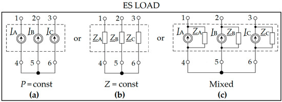
Figure 4.
Electrical multipole representing an electrical receiver of the type: (a) constant power, model J; (b) constant impedance, model RL; (c) mixed, model JRL.
Depending on the receiver type, the following data should be entered into the application: impedance profiles (resistance and reactance) should be entered into the RL model, active and reactive power profiles should be entered into the J model, and both active and reactive power profiles and impedance profiles should be entered into the JRL model. The distributed generation model consists of three branches, each of which uses a branch with a current source, model J. Thanks to this action, it is possible to introduce a real generation profile in each phase to the developed application. Data on load profiles (power profiles, impedance profiles, and PV power generation profiles) were obtained from real technical objects, which were presented in [33]. The simulation studies were carried out for a period of one day.
In order to determine the impact of the receiver type and the supply voltage on electrical energy losses, three variants of the system operation were considered:
- No distributed generation (basic variant, Figure 5);
- A three-phase photovoltaic installation with a rated power of 5 kW is connected to consumer 3 and 4, while consumer 5 is connected to a 10 kW photovoltaic installation (Figure 6);
- Three photovoltaic installations (2 × 5 kW and 10 kW) were connected to a free line bay in the low-voltage switchgear, which is powered by the MV/LV transformer (Figure 7).
As part of the considered variants of the operation of the analyzed fragment of the power grid operation with distributed generation, the receiver type was changed in order to determine the energy losses in the grid. For each of the variants, it was first considered that we are dealing with constant-impedance receivers, followed by constant-power receivers, and, in the final case, with mixed receivers. Each mixed load was modeled as a parallel connection of a constant power and constant impedance load in the proportion of 50% of the rated power for each type of load.
In addition to distributed generation, its location, and the type of receiver, our research also examined the impact of changing the voltage supplying the power grid on energy losses in the network. Three variants of the supply voltage were considered: nominal (400 V), increased (420 V), and reduced (380 V).
In order to determine the impact of the type of load, distributed generation and its location as well as changes in the supply voltage on electrical energy losses in overhead lines, cable lines, and the transformer, 27 variants of the system operation were considered. The assessment measures are as follows: daily active energy losses, taking into account energy losses on all sections of the overhead and cable lines and in the transformer; daily electrical energy consumption; the percentage share of active energy losses related to the daily electrical energy consumption; the value of the voltage supplying the receivers at the end of the analyzed part of the power grid.
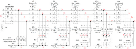
Figure 5.
Diagram of the analyzed network as a combination of electric multipoles for the second part of the experiment—a system without distributed generation.
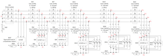
Figure 6.
Diagram of the analyzed network as a connection of electric multipoles for the second part of the experiment—system with distributed generation at recipient no. 3, 4, and 5.

Figure 7.
Diagram of the analyzed network as a connection of electric multipoles for the second part of the experiment—a system with distributed generation installed at the beginning of the analyzed line.
3. Results
Table 2 presents the results of the first part of the tests, in which water was heated in the boiler (a constant amount of electrical energy, Qe = 4.42 kWh, was supplied).

Table 2.
Results of the first part of the research on determining energy losses when heating water in the heating device.
Table 2.
Results of the first part of the research on determining energy losses when heating water in the heating device.
| Type of a Receiver | Vsupply (V) | theat (min) | ΔEc (Wh) |
|---|---|---|---|
| Constant impedance receiver Z = const (PN = 2 kW) | 207 | 164 | 36.6 |
| 230 | 132 | 36.6 | |
| 253 | 110 | 36.6 | |
| Constant power receiver P = const (PN = 2 kW) | 207 | 132 | 45.2 |
| 230 | 132 | 36.6 | |
| 253 | 132 | 30.2 | |
| Mixed receiver (Z = const + P = const) (PN = 1 kW + 1 kW) | 207 | 152 | 38.9 |
| 230 | 132 | 36.6 | |
| 253 | 124 | 31.8 |
On the basis of the simulation results obtained from the first part of the research, which are presented in Table 2, it can be seen that, in order to supply the same amount of energy to the system, the value of the supply voltage for constant impedance receivers has no effect on the amount of electrical energy losses (they are constant). If the receiver is supplied with a higher voltage, it will consume more power, which will heat the water in a shorter time. Similarly, with a lower voltage, the receiver will consume less power, which will heat the water in a longer time. A lower current in a longer time will cause the same amount of heat to be released in the resistance of the power cable as a higher current in a shorter time.
In the case of constant power receivers, where the heating time is constant (P = const), depending on the supply voltage, the losses change—a higher value of the supply voltage causes a lower value of the electric current, and a smaller electric current, according to the Joule–Lenz law (), causes lower energy losses, while a lower voltage causes a higher current, which results in higher losses. In the case of a mixed receiver in which the ratio of rated power of the receivers is 1:1, the value of the supply voltage is important: the higher the voltage, the lower the active energy losses, which results from the influence of the constant power receiver part, while the lower the voltage, the lower the losses, which results from the influence of the part of the constant impedance receiver. For increased voltage, energy losses for a mixed receiver are lower than for a constant impedance receiver by about 13%, while these losses are higher than for a constant power receiver by about 5.2%. For a lowered voltage, energy losses for a mixed load are higher than for a constant impedance load by about 6.3%, and these losses are lower than in the case of a constant power load by about 14%.
Table 2 shows the active energy losses for a mixed load in the case of 50% of the rated power (1 kW + 1 kW). In further studies aimed at presenting the influence of the supply voltage on energy losses for a mixed load, simulations were carried out by changing the percentage of the share of the low-power receiver in relation to the share of the fixed-impedance receiver. The share percentage changed from 100% to 0%, which means that with 100% share we have a constant power receiver, and with 0% share, we have a constant impedance receiver. The results of the simulation are presented in Figure 8 in the form of a graph of electrical energy losses depending on changes in the supply voltage and changes in the proportion of the share of the receiver type (for Qe = const)
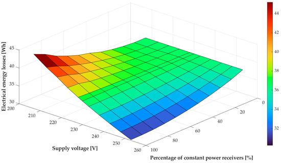
Figure 8.
Graph of changes in electrical energy losses as a function of changes in the supply voltage and changes in the proportion of the share of the type of receiver.
Based on the above graph, it can be seen that, for the rated voltage, it does not matter whether it is a constant power, constant impedance, or mixed receiver (assuming their equal power at the rated voltage): the losses of electrical energy are constant. It is also confirmed that when the load is dominated by constant power receivers, the energy losses are greater for a lower voltage value and smaller for a higher voltage value. The percentage increase in the share of constant impedance receivers causes the decrease in the steepness of the losses as a function of voltage changes until they are completely equalized for the constant impedance receivers.
Table 3 presents the results of the research on the second part of the experiment related to the determination of active energy losses in the model of a rural low-voltage power grid performed in accordance with the description and methodology contained in the previous chapter.

Table 3.
Results of the second part of the experiment.
Table 3.
Results of the second part of the experiment.
| Distributed Generation | Vsupply (V) | Load | Ec (kWh) | ΔEc (kWh) | %ΔEc (%) |
|---|---|---|---|---|---|
| None | 400 | Z = const | 278 | 0.645 | 0.23 |
| P = const | 278 | 0.645 | 0.23 | ||
| P = const + Z = const | 278 | 0.645 | 0.23 | ||
| 420 | Z = const | 309 | 0.714 | 0.23 | |
| P = const | 278 | 0.591 | 0.21 | ||
| P = const + Z = const | 293 | 0.651 | 0.22 | ||
| 380 | Z = const | 253 | 0.584 | 0.23 | |
| P = const | 278 | 0.724 | 0.26 | ||
| P = const + Z = const | 265 | 0.651 | 0.25 | ||
| PV located deep in the grid | 400 | Z = const | 283 | 6.39 | 2.21 |
| P = const | 278 | 6.58 | 2.30 | ||
| P = const + Z = const | 280 | 6.47 | 2.25 | ||
| 420 | Z = const | 311 | 5.75 | 1.81 | |
| P = const | 278 | 5.98 | 2.11 | ||
| P = const + Z = const | 295 | 5.90 | 1.95 | ||
| 380 | Z = const | 255 | 7.14 | 2.72 | |
| P = const | 278 | 7.18 | 2.52 | ||
| P = const + Z = const | 267 | 7.16 | 2.61 | ||
| PV at the MV/LV transformer station | 400 | Z = const | 280 | 0.533 | 0.19 |
| P = const | 278 | 0.538 | 0.19 | ||
| P = const + Z = const | 279 | 0.536 | 0.19 | ||
| 420 | Z = const | 309 | 0.584 | 0.19 | |
| P = const | 278 | 0.483 | 0.17 | ||
| P = const + Z = const | 294 | 0.535 | 0.18 | ||
| 380 | Z = const | 253 | 0.488 | 0.19 | |
| P = const | 278 | 0.597 | 0.21 | ||
| P = const + Z = const | 266 | 0.540 | 0.20 |
Based on the obtained results, it can be seen that, for the variants without distributed generation, when supplied with a rated voltage of 400 V, as expected, the energy consumption by various types of consumers and active energy losses are the same, and they account for 0.23% of the total energy consumption. Changing the supply voltage causes, in the case of constant-impedance receivers, the daily energy consumption and energy losses to change (when the voltage is increased, electrical energy consumption and energy losses will increase; when the voltage is reduced, energy consumption and energy losses will decrease), but the percentage share of energy losses remains unchanged. On the other hand, in the case of constant power receivers, increasing the supply voltage in the absence of distributed generation causes a decrease in energy losses (lower current flow) at constant power and, consequently, constant energy consumption, which also reduces the percentage of active energy losses, while reducing the supply voltage increases energy loss. In the case of mixed receivers, energy losses increase with increasing voltage (however, they are lower than in the case of constant-impedance receivers and higher than in the case of constant-power receivers), and with the voltage decrease, these losses decrease (however, they are lower than in the case of constant-power receivers and higher than in the case of constant-power receivers). For mixed receivers, it turned out that although the daily consumption of active electrical energy changed with the change in the supply voltage, the daily losses of active energy remained at the same level (a small difference of 0.006 kWh). For the considered fragment of the network, a change in the supply voltage and using different types of receivers without distributed generation has an insignificant effect on energy losses. The biggest difference is about 0.08 kWh.
Table 4 presents electrical energy losses in each of the analyzed cases, broken down into electrical energy losses in the transformer and electrical energy losses in power lines.

Table 4.
Results on electrical energy losses for the second part of the research, divided into losses in the transformer and power lines.
Table 4.
Results on electrical energy losses for the second part of the research, divided into losses in the transformer and power lines.
| Distributed Generation | Vsupply (V) | Load | Electrical Energy Losses in the Transformer (kWh) | Electrical Energy Losses in Power Lines (kWh) |
|---|---|---|---|---|
| None | 400 | Z = const | 0.28 | 0.38 |
| P = const | 0.28 | 0.38 | ||
| P = const + Z = const | 0.28 | 0.38 | ||
| 420 | Z = const | 0.30 | 0.41 | |
| P = const | 0.25 | 0.34 | ||
| P = const + Z = const | 0.27 | 0.38 | ||
| 380 | Z = const | 0.25 | 0.34 | |
| P = const | 0.30 | 0.42 | ||
| P = const + Z = const | 0.27 | 0.38 | ||
| PV located deep in the grid | 400 | Z = const | 0.16 | 6.24 |
| P = const | 0.15 | 6.38 | ||
| P = const + Z = const | 0.15 | 6.31 | ||
| 420 | Z = const | 0.17 | 5.58 | |
| P = const | 0.14 | 5.84 | ||
| P = const + Z = const | 0.15 | 5.71 | ||
| 380 | Z = const | 0.14 | 7.00 | |
| P = const | 0.17 | 7.01 | ||
| P = const + Z = const | 0.16 | 7.00 | ||
| PV at the MV/LV transformer station | 400 | Z = const | 0.16 | 0.37 |
| P = const | 0.16 | 0.38 | ||
| P = const + Z = const | 0.16 | 0.38 | ||
| 420 | Z = const | 0.17 | 0.41 | |
| P = const | 0.14 | 0.34 | ||
| P = const + Z = const | 0.16 | 0.38 | ||
| 380 | Z = const | 0.15 | 0.34 | |
| P = const | 0.18 | 0.42 | ||
| P = const + Z = const | 0.16 | 0.38 |
Analyzing the presented results, it can be observed that the location of the photovoltaic installation is very important for electrical energy losses. In the case when photovoltaic installations are connected in the depth of the network, electrical energy losses in the lines are about 7.00 kWh, while in the case of connecting them to the main LV switchgear next to the transformer, the losses are 0.38 kWh. The analysis showed that, for the considered case, electrical energy losses are lower by more than 18 times compared to the case when PV installations are connected in the depth of the grid. The location of the PV at the MV/LV transformer station causes the losses in the power lines to be almost identical to those in the basic variant, in which there is no PV. This is due to the fact that the surplus of electrical energy does not have to be transferred from the PV installation through lines to the transformer station but can go directly to the transformer. The electrical energy losses in the transformer when the PV is located deep in the grid or when the PV is located at the MV/LV transformer station are almost identical. The analysis of the results shows that, for the considered fragment of the network, the change in the supply voltage and using different types of receivers with distributed generation significantly affects energy losses. The biggest difference is about 0.7 kWh. Distributed generation connected deep into the network for the considered case study also causes a number of voltage problems—it may turn out that in certain areas of the network, and in some parts of the network, the voltage may exceed the permissible values resulting from the PN-EN 50160 standard. Figure 9, Figure 10 and Figure 11 show the waveforms of changes in the phase voltage V1 at the end of the line (ES23) for the variants depending on the distributed generation and the value of the supply voltage.
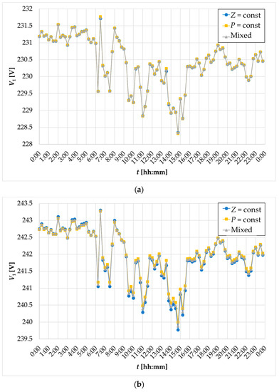
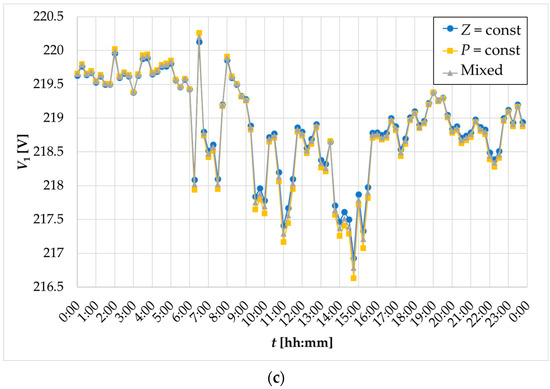
Figure 9.
Waveforms of changes in the phase voltage V1 at the end of the line (ES23) for variants without distributed generation: (a) for supply voltage V = 400 V; (b) for supply voltage V = 420 V; (c) for supply voltage V = 380 V.
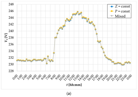
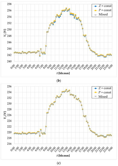
Figure 10.
Waveforms of changes in the phase voltage V1 at the end of the line (ES23) for variants with distributed generation at consumers no. 3, 4, and 5 (ES13, ES16, and ES23): (a) for supply voltage V = 400 V; (b) for supply voltage V = 420 V; (c) for supply voltage V = 380 V.
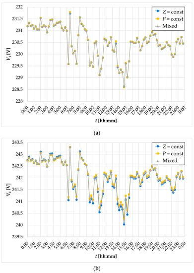
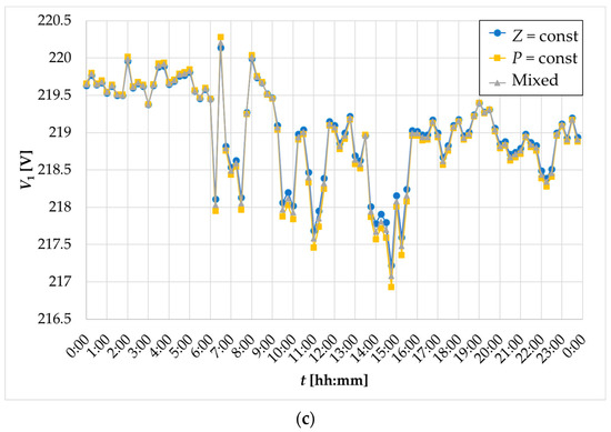
Figure 11.
Waveforms of changes in the phase voltage V1 at the end of the line (ES23) for variants with distributed generation at the MV/LV transformer station: (a) for supply voltage V = 400 V; (b) for supply voltage V = 420 V; (c) for supply voltage V = 380 V.
As shown in Figure 10, the distributed generation located deep in the network (especially in the case of networks with a relatively high impedance, such as the one under analysis) may experience a large increase in voltage above the normative value. Such a voltage value may cause damage to receivers supplied from this phase. In a real system, such a voltage increase resulting from power generation from PV should not happen because the overvoltage protection in PV inverters should turn off such a generating unit, which reduces energy efficiency and the investor’s losses due to unproduced electrical energy. It can also be noticed by analyzing the waveforms shown in Figure 9, Figure 10 and Figure 11 that the type of receiver has no significant impact on the course of changes in the supply voltage.
The solution to the problem of increased energy losses resulting from giving excess power to the grid, shown in the case of locating photovoltaic installations in the “deep” part of the grid at consumers, is to connect these installations directly at the MV/LV transformer station. As can be seen from Table 4, the losses in such cases are even lower than in the case of the base variants without distributed generation. For the considered case, this results from the reduction in energy losses in the transformer, while electrical energy losses in overhead and cable lines are at a similar level to that of the variant without generation. This results in a lower percentage of electrical energy losses in relation to total consumption than in the previous cases. Changing the supply voltage of the tested section of the line depending on the type of receiver affects the level of energy losses in the same way as described for the first experiment. For the considered fragment of the network, the change in the supply voltage and with different types of receivers with distributed generation located at the transformer station insignificantly affects energy losses. The biggest difference is about 0.07 kWh.
Additionally, when analyzing the course of changes in the phase voltage at the end user, it can be seen that these courses are almost identical to those for variants without distributed generation, and there are no voltages exceeding the norm, even for an increased supply voltage of Vsupply = 420 V.
4. Conclusions
This article presents the impact of the type of receivers on the operation of the low-voltage power grid, which was simulated in the authors’ model developed on the basis of the electric multipole method and Newton’s method. The proposed method makes it possible to simulate different variants of the network operation, with different types of receivers, taking into account the asymmetry, the method of earthing the neutral point, and distributed generation without the use of specialized programs for flow calculations. An approach to a comprehensive analysis related to the issue of energy losses due to changes in the supply voltage for various types of receivers may prove valuable and crucial in the context of energy management in households and energy billing in future locally balanced energy systems, which should take into account the co-creation of the energy market based on all participants (users) of the network.
The tests carried out on two objects allow for the formulation of a number of conclusions. From the analysis of the results obtained for the first part of the network, we can conclude the following:
- In the case of constant impedance receivers, while supplying the same amount of energy to the system, the value of the supply voltage does not affect the level of energy losses (they are constant).
- In the case of constant power receivers, while supplying the same amount of energy to the system, an increase in the supply voltage reduces energy losses, and a decrease in voltage increases energy losses.
- In the case of mixed receivers, while supplying the same amount of energy to the system, the greater the share of constant power receivers, the greater the impact the value of the supply voltage has on the level of energy losses.
From the analysis of the results obtained for the second part of the network, we can conclude the following:
- Depending on the type of receiver connected to the low-voltage power grid and the supply voltage without distributed generation, the level of energy losses in the grid changes; however, for the considered cases, the impact is negligible (imperceptible)—about 0.03%.
- The location of distributed generation has a significant impact on electrical energy losses in the considered power grid—the analysis showed that connecting generation in the depth of the network will increase energy losses by 20% compared to without it. This is due to the lack of the self-consumption of power generated from photovoltaic installations by the recipient. Therefore, part of the power is returned to the grid, and the direction of electric power transmission changes. The consequence is that the value of the supply voltage of the consumers connected to this network increases in the network, as well as the loss of electrical energy. The increase in the voltage in the grid will also contribute to a longer payback period for the prosumer installation because each PV inverter should disconnect from the grid in the event of exceeding the normative values as a result of the activation of the overvoltage protections in it. For the considered case, it can be seen that the type of receiver connected to the grid and the supply voltage of the system have a greater impact on energy losses (the difference is up to 0.5%) than in the system without generation.
- Energy losses in low-voltage power grids can be reduced by locating distributed generation at MV/LV transformer stations. This can be achieved because the energy produced by the source is sent via lines to consumers, and the surplus energy is transformed into the medium-voltage grid. Connecting the distributed generation to the LV switchgear of the MV/LV transformer station also contributes to the improvement of the voltage conditions in the network, thanks to which the value of the supply voltage in the entire section of the line is within the range of ±10% VN—rated voltage, in accordance with the PN-EN 50160 standard. This will result in a lack of the disconnection of the PV installation due to the activation of the protections in the inverter.
In the context of future directions of scientific activities, the authors plan research related to the management and control of the operation of a low-voltage power grid with a large penetration of distributed generation. The tests carried out for the purposes of this article allowed for the identification of features, conditions, and factors that affect the operation of the power grid in terms of electrical energy losses and changes in the voltage profile. This will allow for the development and validation of adaptive algorithms for controlling the operation of the power grid with distributed generation by all participants of the electricity market, taking into account not only the nature of the recipient (resistive, capacitive, or inductive) but also the type of recipient (constant power, constant impedance, or mixed). In the future, it will also allow for the development of mechanisms enabling billing for energy within the analyzed system.
Author Contributions
Conceptualization, Z.K. and Ł.M.; methodology, Ł.M. and Z.K.; software, Ł.M. and Z.K.; validation, Z.K.; formal analysis, Z.K. and Ł.M.; investigation, Ł.M.; resources, Z.K.; data curation, Z.K.; writing—original draft preparation, Ł.M.; writing—review and editing, Z.K.; visualization, Ł.M.; supervision, Z.K. All authors have read and agreed to the published version of the manuscript.
Funding
This research received no external funding.
Data Availability Statement
Not applicable.
Conflicts of Interest
The authors declare no conflict of interest.
References
- Brożek, J. The influence of the dispersed generation on the power and energy losses in an electric power distribution network. Przegląd Elektrotechn. 2006, 89, 101–103. (In Polish) [Google Scholar]
- Cieślik, S. Simulation analysis of active power loss in LV power network with distributed microgeneration with on-load voltage control. Poznań Univ. Technol. Acad. J. Electr. Eng. 2015, 82, 101–111. (In Polish) [Google Scholar]
- Salimon, S.A.; Adepoju, G.A.; Adebayo, I.G.; Howlader, H.O.R.; Ayanlade, S.O.; Adewuyi, O.B. Impact of Distributed Generators Penetration Level on the Power Loss and Voltage Profile of Radial Distribution Networks. Energies 2023, 16, 1943. [Google Scholar] [CrossRef]
- Ogunjuyigbe, A.S.; Ayodele, T.R.; Akinola, O.O. Impact of distributed generators on the power loss and voltage profile of sub-transmission network. J. Electr. Syst. Inf. Technol. 2016, 3, 94–107. [Google Scholar] [CrossRef]
- Czapp, S.; Sarnicki, M.; Tarakan, B.; Tarakan, K.; Zajczyk, R. Impact of distributed generation on active power losses in HV and MV distribution networks. In Proceedings of the 7th Scientific and Technical Conference on Electrical energy Loss in Power Grids, Kołobrzeg, Poland, 8–9 June 2016; pp. 19–28. (In Polish). [Google Scholar]
- Pijarski, P.; Kacejko, P.; Miller, P. Advanced Optimisation and Forecasting Methods in Power Engineering—Introduction to the Special Issue. Energies 2023, 16, 2804. [Google Scholar] [CrossRef]
- Dharavat, N.; Sudabattula, S.K.; Velamuri, S.; Mishra, S.; Sharma, N.K.; Bajaj, M.; Elgamli, E.; Shouran, M.; Kamel, S. Optimal Allocation of Renewable Distributed Generators and Electric Vehicles in a Distribution System Using the Political Optimization Algorithm. Energies 2022, 15, 6698. [Google Scholar] [CrossRef]
- Mohamed Diaaeldin, I.; Abdel Aleem, S.H.E.; El-Rafei, A.; Abdelaziz, A.Y.; Zobaa, A.F. A Novel Graphically-Based Network Reconfiguration for Power Loss Minimization in Large Distribution Systems. Mathematics 2019, 7, 1182. [Google Scholar] [CrossRef]
- Onlam, A.; Yodphet, D.; Chatthaworn, R.; Surawanitkun, C.; Siritaratiwat, A.; Khunkitti, P. Power Loss Minimization and Voltage Stability Improvement in Electrical Distribution System via Network Reconfiguration and Distributed Generation Placement Using Novel Adaptive Shuffled Frogs Leaping Algorithm. Energies 2019, 12, 553. [Google Scholar] [CrossRef]
- Ntombela, M.; Musasa, K.; Leoaneka, M.C. Power Loss Minimization and Voltage Profile Improvement by System Reconfiguration, DG Sizing, and Placement. Computation 2022, 10, 180. [Google Scholar] [CrossRef]
- Abd El-salam, M.F.; Beshr, E.; Eteiba, M.B. A New Hybrid Technique for Minimizing Power Losses in a Distribution System by Optimal Sizing and Siting of Distributed Generators with Network Reconfiguration. Energies 2018, 11, 3351. [Google Scholar] [CrossRef]
- Ali, M.H.; El-Rifaie, A.M.; Youssef, A.A.F.; Tulsky, V.N.; Tolba, M.A. Techno-Economic Strategy for the Load Dispatch and Power Flow in Power Grids Using Peafowl Optimization Algorithm. Energies 2023, 16, 846. [Google Scholar] [CrossRef]
- Abbas, M.; Alshehri, M.A.; Barnawi, A.B. Potential Contribution of the Grey Wolf Optimization Algorithm in Reducing Active Power Losses in Electrical Power Systems. Appl. Sci. 2022, 12, 6177. [Google Scholar] [CrossRef]
- Hraiz, M.D.; Garcia, J.A.M.; Jimenez Castaneda, R.; Muhsen, H. Optimal PV Size and Location to Reduce Active Power Losses While Achieving Very High Penetration Level with Improvement in Voltage Profile Using Modified Jaya Algorithm. IEEE J. Photovolt. 2020, 10, 1166–1174. [Google Scholar] [CrossRef]
- Kumar, M.V.; Bilgundi, S.K.; Pradeepa, H. Optimal allocation of DG units in distribution system considering variation in active power load. Arch. Electr. Eng. 2019, 68, 265–277. [Google Scholar] [CrossRef]
- Beza, T.M.; Huang, Y.-C.; Kuo, C.-C. A Hybrid Optimization Approach for Power Loss Reduction and DG Penetration Level Increment in Electrical Distribution Network. Energies 2020, 13, 6008. [Google Scholar] [CrossRef]
- Shanmugapriyan, J.; Karuppiah, N.; Muthubalaji, S.; Tamilselvi, S. Optimum placement of multi type DG units for loss reduction in a radial distribution system considering the distributed generation. Bull. Pol. Acad. Sci. Tech. Sci. 2018, 66, 345–354. [Google Scholar] [CrossRef]
- Tuzikova, V.; Tlusty, J.; Muller, Z. A Novel Power Losses Reduction Method Based on a Particle Swarm Optimization Algorithm Using STATCOM. Energies 2018, 11, 2851. [Google Scholar] [CrossRef]
- Suresh, V.; Janik, P.; Jasinski, M. Metaheuristic approach to optimal power flow using mixed integer distributed ant colony optimization. Arch. Electr. Eng. 2020, 69, 335–348. [Google Scholar] [CrossRef]
- Pál, D.; Beňa, Ľ.; Kolcun, M.; Čonka, Z. Optimization of Active Power Losses in Smart Grids Using Photovoltaic Power Plants. Energies 2022, 15, 739. [Google Scholar] [CrossRef]
- Khwanrit, R.; Lim, Y.; Javaid, S.; Kittipiyakul, S.; Tan, Y. Study of Energy Loss for Distributed Power-Flow Assignment in a Smart Home Environment. Designs 2022, 6, 99. [Google Scholar] [CrossRef]
- Mikulski, S.; Tomczewski, A. Use of Energy Storage to Reduce Transmission Losses in Meshed Power Distribution Networks. Energies 2021, 14, 7304. [Google Scholar] [CrossRef]
- Adegoke, S.A.; Sun, Y. Diminishing Active Power Loss and Improving Voltage Profile Using an Improved Pathfinder Algorithm Based on Inertia Weight. Energies 2023, 16, 1270. [Google Scholar] [CrossRef]
- Nguyen, T.T.; Dinh, B.H.; Pham, T.D.; Nguyen, T.T. Active Power Loss Reduction for Radial Distribution Systems by Placing Capacitors and PV Systems with Geography Location Constraints. Sustainability 2020, 12, 7806. [Google Scholar] [CrossRef]
- Al Ameri, A.; Ounissa, A.; Nichita, C.; Djamal, A. Power Loss Analysis for Wind Power Grid Integration Based on Weibull Distribution. Energies 2017, 10, 463. [Google Scholar] [CrossRef]
- Vlahinić, S.; Franković, D.; Komen, V.; Antonić, A. Reactive Power Compensation with PV Inverters for System Loss Reduction. Energies 2019, 12, 4062. [Google Scholar] [CrossRef]
- Addurat, A.S.; Pasupuleti, J. The impacts of number of solar photovoltaic units on distribution network losses and voltage profile. In Proceedings of the 2020 IEEE Student Conference on Research and Development (SCOReD), Batu Pahat, Malaysia, 27–29 September 2020; IEEE: Toulouse, France, 2020; pp. 249–253. [Google Scholar] [CrossRef]
- Tran, Q.T.T.; Riva Sanseverino, E.; Zizzo, G.; Di Silvestre, M.L.; Nguyen, T.L.; Tran, Q.-T. Real-Time Minimization Power Losses by Driven Primary Regulation in Islanded Microgrids. Energies 2020, 13, 451. [Google Scholar] [CrossRef]
- Otcenasova, A.; Bolf, A.; Altus, J.; Regula, M. The Influence of Power Quality Indices on Active Power Losses in a Local Distribution Grid. Energies 2019, 12, 1389. [Google Scholar] [CrossRef]
- Cieślik, S. Energy losses in the lv power network with prosumer microinstallations. Rynek Energii 2020, 1, 18–24. (In Polish) [Google Scholar]
- Mazur, Ł.; Cieślik, S.; Czapp, S. Trends in Locally Balanced Energy Systems without the Use of Fossil Fuels: A Review. Energies 2023, 16, 4551. [Google Scholar] [CrossRef]
- Cieślik, S. Mathematical Modeling and Simulation of Electric Power Systems with Induction Generators; Wydawnictwo Uczelniane Uniwersytetu Technologiczno-Przyrodniczego w Bydgoszczy: Bydgoszcz, Poland, 2008. (In Polish) [Google Scholar]
- Mazur, Ł.; Kłosowski, Z. A New Approach to the Use of Energy from Renewable Sources in Low-Voltage Power Distribution Networks. Energies 2023, 16, 727. [Google Scholar] [CrossRef]
- Cieślik, S. Mathematical Modeling of the Dynamics of Linear Electrical Systems with Parallel Calculations. Energies 2021, 14, 2930. [Google Scholar] [CrossRef]
- Kłosowski, Z.; Cieślik, S. Real-Time Simulation of Power Conversion in Doubly Fed Induction Machine. Energies 2020, 13, 673. [Google Scholar] [CrossRef]
Disclaimer/Publisher’s Note: The statements, opinions and data contained in all publications are solely those of the individual author(s) and contributor(s) and not of MDPI and/or the editor(s). MDPI and/or the editor(s) disclaim responsibility for any injury to people or property resulting from any ideas, methods, instructions or products referred to in the content. |
© 2023 by the authors. Licensee MDPI, Basel, Switzerland. This article is an open access article distributed under the terms and conditions of the Creative Commons Attribution (CC BY) license (https://creativecommons.org/licenses/by/4.0/).