Abstract
The output active power of a grid-connected inverter controlled by a traditional virtual synchronous generator (VSG) has the problems of oscillation and steady-state errors. A VSG control strategy based on improved damping and angular frequency deviation feedforward is proposed. This strategy reduces the steady-state error of active power by adding a transient damping link to a traditional VSG damping feedback channel. At the same time, the angular frequency deviation feedforward compensation is used to improve the response speed of the VSG to the active power instruction and reduce the active power overshoot in the dynamic process. First, the VSG active power closed-loop small-signal model is established. The effects of inertia and damping on the dynamic and steady-state performance of the VSG are analyzed by the root locus method. The effect of the proposed control strategy on the system is analyzed by using a closed-loop zero-pole diagram. This strategy improves the precision of active power control the dynamic performance of the system effectively. Finally, the effectiveness and superiority of the proposed control strategy are verified by Matlab/Simulink simulation and semi-physical simulation platform RT-LAB.
1. Introduction
The construction of a new power system is a major need for the implementation of China’s new energy security strategy and to achieve the “30–60” carbon-neutral climate response target. By the end of December 2021, the cumulative installed capacity of renewable energy generation nationwide was 1.06 billion kW, accounting for 44.8% of all electricity installed, including 306 million kW of photovoltaic power, 328 million kW of wind power, and 391 million kW of hydropower. With a high proportion of renewable energy connected to the grid, the inertia of a power system gradually decreases, making the system less able to resist interference and maintain stable operations. The random and fluctuating nature of renewable energy sources causes fluctuations in the frequency and voltage amplitude of the grid, further exacerbating this adverse situation and seriously threatening the safe and stable operation of a power system [1,2,3]. In order to adapt to the needs of distributed power development, to meet the requirements set out in the certification system, and to increase the grid penetration of distributed power sources, the main grid-connected inverter control schemes are PQ control, VF control, droop control, and virtual synchronous control. Virtual synchronous generator (VSG) technology has attracted the attention of scholars at home and abroad by simulating the characteristics of a synchronous generator (SG) and increasing the inertia of the system, thereby effectively improving the system voltage and frequency support capability [4,5,6,7,8,9,10].
Existing virtual generator technologies can be divided into two main categories: current-controlled virtual synchronous generator technologies and voltage-controlled virtual synchronous generator technologies [11,12,13,14,15,16,17,18] From the grid perspective, the former is equivalent to a controlled current source and is suitable for grid-connected operation control applications in grid environments with a low penetration of distributed power sources, while the latter is equivalent to a controlled voltage source and is suitable for grid-connected operation control in weak grid environments with a high penetration of distributed power sources and for voltage reference control applications in a microgrid islanding mode of operation. This paper addresses the discussion of voltage-based virtual synchronous generators. In [19] the principle of power oscillation caused by virtual inertia and the influence of the damping coefficient on the dynamic and steady-state characteristics of a VSG are analyzed. In [20], the concept of virtual power was proposed to add differential correction links to the conventional VSG control forward channel and damped feedback channel to meet the control quality requirements of different frequency bands by changing their dynamic and static characteristics. This addresses the shortcomings of the traditional virtual synchronous generator technique, which introduces a differential link that affects the oscillation frequency and has a reduced effect on noise suppression. Ref. [21] shows through an impedance analysis that the VSG interacts with the weak grid and thus excites low- and high-frequency oscillations. An inertial damping enhancement method is proposed to improve the frequency dynamics response and extend the stability margin, but this method is more complex for the selection of coefficients. Ref. [22] uses an alternating inertia control structure, taking into account its virtual angular velocity and the acceleration and deceleration of each oscillation phase. By choosing larger values of the moment of inertia during acceleration, it is possible to mitigate this; on the other hand, the deceleration effect is increased by using smaller values of the inertia coefficient during deceleration. The control still deviates due to the fixed values of the selected parameters. In [23], a damping term produced from a state feedback control is added to a VSG control to solve this issue. This method applies a low pass filter to the measured active power to improve its ripple attenuation ability at the cost of increased design complexity.
The above-mentioned literature has made it difficult to achieve consistent improvements in the dynamic and static performance indicators of the system by changing the inertia and damping of the virtual synchronous generator for better control of the system due to the contradiction between the steady-state deviation of the active power of the VSG and the dynamic shock regulation. Therefore, VSGs operating in grid-connected mode using existing strategies are unable to meet the steady-state and dynamic control requirements. To optimize the dynamic and static characteristics of the virtual synchronous generator (VSG), this paper conducts a detailed analysis of the interplay between its dynamic regulation traits and static indicators. By examining the fundamental operating principles of the VSG, the study highlights existing contradictions. Then, the relationship between the inertia damping of VSG is analyzed and the VSG control strategy with improved damping and angular frequency deviation feedforward is proposed. Finally, the effectiveness and superiority of the proposed control strategy are verified by MATLAB/Simulink simulation and RT-LAB experiments.
2. Fundamentals of VSG Active Control
The topology and control block diagram of a VSG grid-connected circuit based on a three-phase voltage source inverter is shown in Figure 1. Udc is the dc-side voltage; Cdc is the dc-bus capacitance; ea, eb, and ec are the inverter terminal voltages; and ia, ib, and ic are the inverter terminal currents. L and C are the filter electricity and filter capacitor, respectively; R is the parasitic resistance of the filter inductor; ua, ub, and uc are the output voltages of the inverter; icabc is the capacitor current; ioa, iob, and ioc are the output currents of the inverter; Pe and Qe are the active and reactive power output by the VSG, respectively; Pref and Qref are the active and reactive power commands issued by the VSG, respectively; ω0 is the set value of the output angular frequency of the VSG; and δ and Em are the power angle and the amplitude of the voltage at the machine end of the VSG, respectively. By detecting the VSG output power in real time and comparing it with the command power, the VSG power angle δ and the voltage amplitude E of the machine are obtained and then the input signal of the double-loop control (including the voltage outer loop control and current inner loop control) is obtained. Finally, the control signal of the inverter is generated by the SPWM modulator to control the on–off of the switching tube to realize the control of the VSG system. The power control component is the focus of this paper.
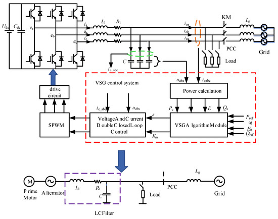
Figure 1.
VSG circuit topology and control block diagram.
VSG control is a control method to control the inverter by simulating the characteristics of a synchronous generator, thereby simulating the inertia and damping of the synchronous generator. The generator has a multi-order mathematical model considering different influencing factors but, in order to simplify the control, its second-order model is mostly used for analysis. Assuming that the synchronous generator is a hidden pole generator with a uniform air gap, there is no need to distinguish between straight and cross-axis reactances.
An equivalent circuit model diagram for a VSG is shown in Figure 2, where E is the VSG excitation electromotive force, U is the grid voltage, Z is the line impedance, and Ia is the grid-connected current value. The VSG is constrained by large power grids under grid-connected conditions, so the grid voltage is used as the reference U ∠ 0. The output phase voltage of the inverter is defined as E ∠ δ, where δ is the phase difference between the two voltage phasors and the work angle. The expression is δ = ∫(ω − ω0)dt, where ω0 is the grid voltage angle frequency, and is the virtual synchronous machine angle frequency.

Figure 2.
VSG equivalent circuit model diagram.
The VSG output current can be expressed as
In Equation (1), Z is the system impedance, including the filter impedance Zfilter and the line impedance Zline; r represents the resistive component in it; and X represents the inductive component where the impedance angle is .
Therefore, the output apparent power of the VSG is
In Equation (2), * denotes the conjugation. From the formula, the VSG output active power P and reactive power Q are:
In general, the line reactance is inductive—that is, —and the power angle δ of the synchronous generator is less than 30°; it can be considered that and . Then, Equation (3) can be simplified as follows:
When the VSG line impedance is inductive, active reactive power can be fully decoupled.
3. Traditional VSG Power Characteristics and Problems
Figure 3 shows the stator voltage vector diagram of a synchronous generator. The stator voltage equation is , where is the inverter output voltage, is the grid voltage, Xs is the impedance value between the inverter output and the grid, and is the current value.
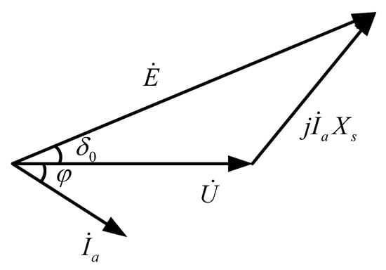
Figure 3.
Synchronous generator stator voltage vector diagram.
The mechanical equation for rotors is
In Equation (5), Pm is the input power of the VSG virtual inertia link, corresponding with the mechanical power of the synchronous generator; Pe is the output power of the VSG, corresponding with the electromagnetic power of the synchronous generator; ω and ωg are the output angular frequency and grid angular frequency of the VSG, respectively; and J and D are the moment of inertia and fixed damping coefficient of the VSG, respectively. At the same time, VSG simulates the sagging characteristics of the exciter and governor of the synchronous generator, so that the inverter can have the functions of primary frequency regulation and primary voltage regulation in the grid-connected mode. The active frequency and reactive voltage droop equations are shown in Equation (6).
where Pref and Qref are the active and reactive power given by the VSG, respectively; Qe is the reactive power output by the VSG; E and E0 are the output voltage amplitude and reference voltage amplitude of the VSG, respectively; and Kω and Kq are the active frequency and reactive voltage droop coefficients of the VSG, respectively. The influence of Kω and D on the dynamic and static characteristics of the VSG can be analyzed by assuming that Kω is unchanged and the influence of Kω and D on the dynamic and static characteristics of the VSG can be analyzed by changing the size of D.
As the response speed of the inner loop of the voltage and current control is much faster than that of the power outer loop, this paper ignores the influence of the dynamic process of the inner loop on the outer loop. The traditional VSG control principle is shown in Figure 4. Using the small-signal modeling and analysis method, the structure diagram of the VSG active power frequency control loop can be obtained, as shown in Figure 4.
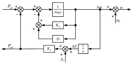
Figure 4.
Traditional VSG control block.
Figure 4 shows the active control block diagram of a VSG. Kδ is the proportional factor of the work angle to the output power, drawing on the small-signal model analysis method of a synchronous generator in the power system; the relationship between the output power of the active small-signal and the given power and angular frequency is shown in Equation (7).
3.1. Static Characteristics and Their Problems
From the equation, it can be obtained that when the steady-state is (t→∞, s→0), the steady-state value of the active change output by the VSG is ΔPref + (Kω + D)Δω. If the power grid is a large power grid, generally Δω = 0 and the steady-state deviation of the VSG output power is 0. If the grid is the end of a large grid or a microgrid, ω may not be equal to ω0 and there is a power deviation of (Kω + D)Δω in the steady-state. The active power error depends on the two parameters Kω and D. When Kω is fixed, the damping coefficient D plays a decisive role in the steady-state power error and when the damping coefficient D is too large, the system has a large steady-state error.
3.2. Dynamic Performance and Their Problems
The VSG active power closed-loop small-signal transfer function is as in Equation (8).
Undamped natural frequencies and damping are as follows:
This is a typical second-order system and oscillation problems occur when the system damping ratio is less than 1. From Equation (9), it can be seen that the undamped oscillation frequency is only related to J and an increase in J can reduce the undamped oscillation frequency. The damping ratio is related to both J and D, and either an increase in D or a decrease in J can increase the damping ratio to reduce the power impact. The natural oscillation frequency of the system is determined by J and it is assumed that the two closed-loop poles are p1 and p2. It can be seen from classical control theory that the dynamic characteristics of the system are determined by p1 and p2. Thus, the position of the closed-loop pole can be changed by revising the inertia factor J and the damping coefficient D during VSG design and the dynamic characteristics of the active power can be adjusted. In order to further discuss its effects, J = 2, 3, 4 and D = 0~20 are taken to plot the zero pole of the system, as shown in Figure 5.
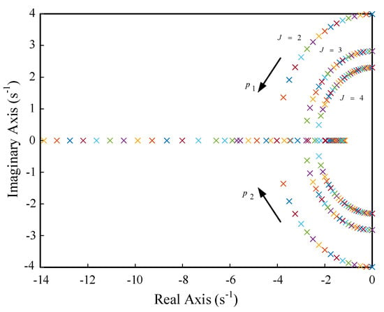
Figure 5.
Pole-zero plot of VSG active small signal.
According to Figure 5, the larger the introduced inertia J, the closer the poles are to the imaginary axis and the more unstable the output active response of the VSG when it responds to sudden changes in the active command of the grid disturbance. As D increases, the conjugate poles of the system gradually move away from the imaginary axis and become closer to the real axis, finally becoming two mutually different negative real poles. The system changes from under-damping to over-damping and the system stability becomes better, indicating that the damping D can improve the system stability and suppress oscillation.
The active power waveforms when J and D take different values are shown in Figure 6 and Figure 7, respectively. In summary, it can be seen that for a typical VSG system, the existence of the inertia coefficient makes its output active response a second-order oscillation system. J mainly determines the frequency of oscillation; the smaller the J, the shorter the system response time and adjustment time and the smaller the maximum active overshoot, but this will increase the peak of frequency overshoot. The larger the J, the stronger the frequency support capacity, but the damping will become smaller and the oscillation more violent. D mainly determines the attenuation rate of oscillation; a fixed damping of D can effectively suppress oscillation, but D is coupled with a frequency modulation parameter, which increases the output active steady-state deviation. The larger the D, the larger the steady-state error. There is a contradiction between the influence of the two parameters on the dynamic and static characteristics of the power during the selection process. Therefore, it is difficult to slow down the active oscillation by directly designing the control parameters of a VSG.
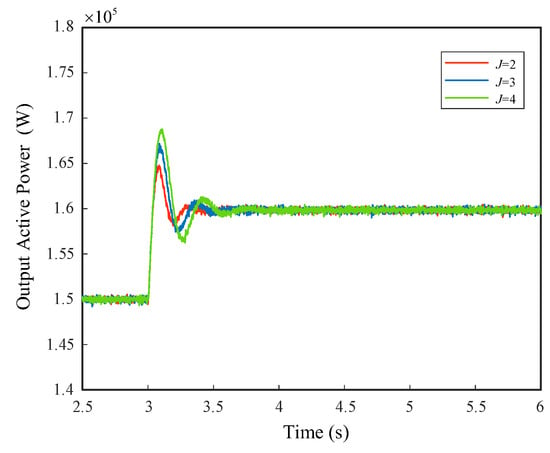
Figure 6.
J-active power diagram with different values.
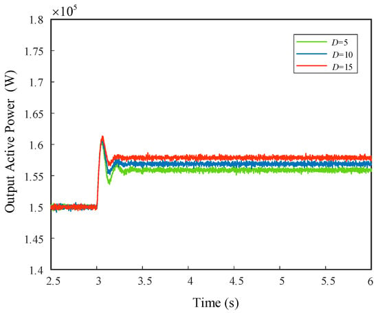
Figure 7.
D-active power diagram with different values.
4. VSG Control Strategy Based on Improved Damping and Angular Frequency Deviation Feedforward
It can be seen from the second section that there is a certain contradiction between the dynamic performance and steady-state performance of a VSG and it is difficult to slow down the active oscillation by directly designing the control parameters of a VSG. Therefore, a VSG control strategy based on improved damping and angular frequency deviation feedforward is proposed, as shown in Figure 8, and the output of the system is shown in Equation (10).
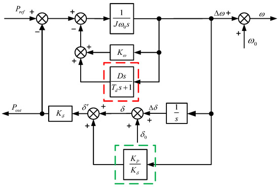
Figure 8.
Damping and angular frequency deviation feedforward block diagram.
4.1. Steady-State Performance
In order to solve the steady-state error caused by excessive D, the improved system steady-state output active power is ΔPout = ΔPref + KωΔω, It can be seen from (10) that the steady-state output active power is composed of a given value of active power ΔPref and a frequency modulation action KωΔω. It can be seen that the introduced strategy eliminates the active power steady-state error caused by the damping coefficient (Kω + D)Δω, part of a traditional VSG.
4.2. Dynamic Performance
The improved inertia damping characteristics obtained from Equation (11), the VSG control active small-signal closed-loop transfer function, are:
4.2.1. The Effect of Td on the Dynamic Performance of the System
In order to simplify the design of damping feedback channel parameters, the original traditional design parameters of the frequency channel (setting Kp = 0 and D = Kω) remain unchanged. Only Td varies between 0.01 and 5, resulting in a system zero-pole distribution, as shown in Figure 9. It can be seen that the zero-pole changes in different frequency bands are different. When Td is small, poles p1 and zero z1 are far from the imaginary axis. Poles p2 and p3 are close to the imaginary axis, which have a great influence on the dynamic characteristics of the system. These are the dominant poles and are mainly affected by Td. As Td increases, the zero point z1 rapidly moves towards the imaginary axis. The poles p2 and p3 move closer to the real axis and meet on the real axis, entering an over-damped state and eliminating oscillation. As Td continues to increase, the zero point z1 approaches the real axis towards the pole p1, forming dipoles, which have less influence on the dynamic characteristics of the system. At the same time, poles p2 and p3 meet and separate on the real axis, becoming the dominant poles. When Td continues to increase, the damping ratio of the system decreases and the stability becomes poor, which is not conducive to suppressing the oscillation of the system.
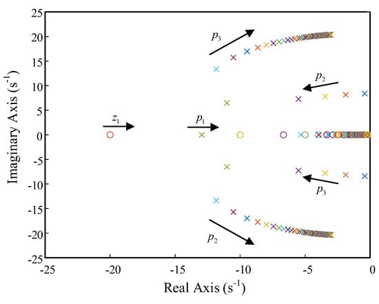
Figure 9.
Improved pole-zero plot when the VSG control strategy Td changes.
4.2.2. The Effect of Kp on the Dynamic Performance of the System
Td = 0.3 should be set to vary only Kp between 1000 and 1500 to obtain the distribution of the zero pole of the system, as shown in Figure 10. It can be seen that the zero pole changes differently in different frequency bands. When Kp is very small, poles p1 and zero z1 form dipoles and zero z2 is far from the imaginary axis, which has little impact on the system; poles p2 and p3 are close to the imaginary axis, which has a greater impact on the dynamic characteristics of the system and become the conjugate dominant pole. As Kp increases, poles p1 and z1 are still dipoles and the zero plot z2 moves towards the imaginary axis; the movement speed gradually slows down, which has little impact on the system. p2 and p3 gradually move closer to the real axis and away from the imaginary axis, becoming the dominant pole, which increases the damping ratio of the system and is conducive to suppressing the oscillation of the system.
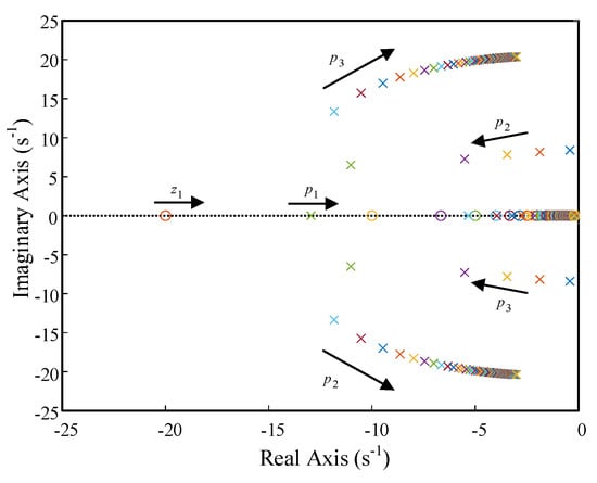
Figure 10.
Improved pole-zero plot when the VSG control strategy Kp changes.
From the above analysis, it can be seen that the dynamic and steady-state performance of the system can be improved by reasonably selecting the values of Td and Kp. The effect of frequency on output power can be analyzed in the same way.
5. Simulation and Experimental Verifications
5.1. Simulation Verification
In order to verify the effectiveness of the VSG control strategy with the improved damping and angular frequency deviation feedforward proposed in this paper, an experimental model of a VSG simulation based on MATLAB/Simulink was built, as shown in Figure 1. The effects of the damped feedback channel on the dynamic and static characteristics of the system, the effects of angular frequency deviation on the static and dynamic characteristics of the system, and the VSG power response with improved damping and angular frequency deviation feedforward were verified, respectively. The simulation parameters are shown in Table 1.

Table 1.
Parameters of the system.
When the simulated working condition was 3 s, the grid frequency dropped by 0.1 Hz due to the sudden load increase or grid failure. The waveforms of each operating condition as the frequency changed are shown in Figure 11a.
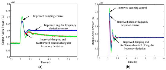
Figure 11.
(a) Grid frequency disturbances; (b) active command perturbation.
At 3 s, the VSG active command was adjusted from 0 kW to 150 kW due to light changes or energy storage regulation. The simulation results are shown in Figure 11b.
It can be seen from Figure 11a that the VSG control strategy proposed in this paper did not have a steady-state error compared with the improved angular frequency deviation feedforward control strategy when the frequency changed; the adjustment time shortened by 0.1 s compared with the improved damping control strategy. The maximum overshoot of active power was close to the improved angular frequency deviation feedforward channel response, and the maximum overshoot of active power reduced by 2% compared with changing the damping feedback channel, which had a good oscillation suppression effect. It can be seen from Figure 11b that when the power changed, the VSG control strategy proposed in this paper shortened the adjustment time by 0.2 s compared with the improved angular frequency deviation feedforward control strategy and the improved damping control strategy. Compared with the control strategy of changing the damping feedback channel, the maximum overshoot of the active power reduced by 4%, which suppressed the active power oscillation.
From the above simulation results, it can be seen that the VSG control strategy with improved damping and angular frequency deviation feedforward could improve the dynamic characteristics of the VSG while eliminating the steady-state active power error and had a good effect on suppressing the active power oscillation. The overall response speed of the system was improved.
5.2. Experimental Verification
In order to further verify the effectiveness of the proposed method, a hardware-in-the-loop experiment was verified on the semi-physical simulation experimental platform RT-LAB. The experimental platform is shown in Figure 12. The system parameters were consistent with the simulation; the working conditions were a 0.1 Hz decrease in the power grid frequency and an active command increase of 150 kW. The experimental results under the active command and grid frequency disturbance are shown in Figure 13 and Figure 14.
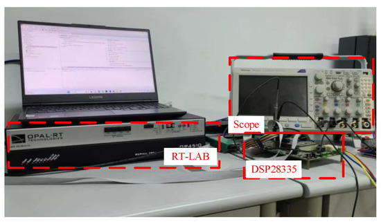
Figure 12.
RT-LAB hardware-in-the-loop test platform.
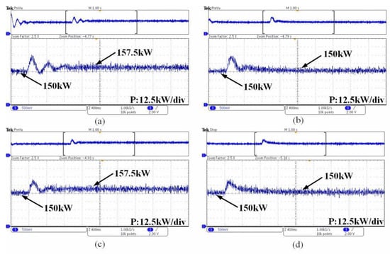
Figure 13.
Grid frequency disturbances. (a) Traditional VSG control strategy; (b)Transient damping VSG control strategy; (c) VSG control strategy of angular frequency deviation feedforward; (d) VSG control strategy based on improved damping and angular frequency deviation feedforward.
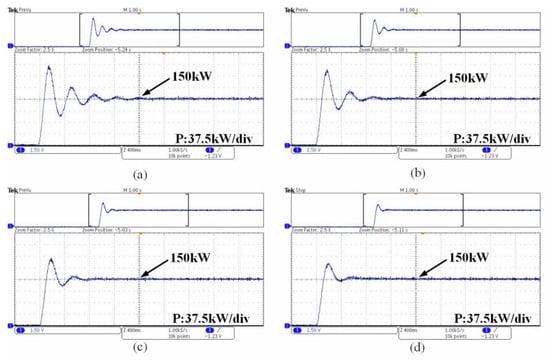
Figure 14.
Active command perturbation. (a) Traditional VSG control strategy; (b) Transient damping VSG control strategy; (c) VSG control strategy of angular frequency deviation feedforward; (d) VSG control strategy based on improved damping and angular frequency deviation feedforward.
Figure 13 shows the active power response of four different control modes under grid frequency disturbances. Figure 14 shows the active power response of four different control modes under active command disturbances. Figure 13a and Figure 14a are the traditional VSG control strategy, Figure 13b and Figure 14b are the transient damping VSG control strategy, Figure 13c and Figure 14c are the VSG control strategy of angular frequency deviation feedforward, and Figure 13d and Figure 14d are the VSG control strategy based on improved damping and angular frequency deviation feedforward. The use of a traditional VSG control produced a steady-state error and large overshoot; the use of a transient damping control could eliminate the error, but there was a large overshoot. The overshoot under active command disturbance was especially very large, which could cause transient current overshoot and could easily cause overcurrent protection. The angular frequency deviation feedforward control strategy could reduce overshoot and suppress system oscillation, but it had a steady-state error. The proposed VSG control strategy based on improved damping and angular frequency deviation feedforward reduced the overshoot and there was no steady-state error under grid frequency disturbance; the experimental results under both disturbances were consistent with the simulation.
6. Conclusions
When a traditional VSG control strategy is running, the control parameters cannot take into account the dynamic and static characteristics of the power response. This paper discusses the working principle and characteristics of a traditional VSG and analyzes the contradiction between the dynamic and static characteristics of a traditional VSG through theory. On this basis, based on classical control theory ideas, a VSG control strategy to improve the damping and angular frequency deviation feedforward was proposed, which achieved the purpose of taking into account the dynamic and static characteristics of the system.
Through the design analysis and simulation of the relevant parameters, the following conclusions were drawn.
- (1)
- The VSG characteristics mainly depended on the inertia coefficient J and the damping coefficient D; the influence of the two parameters on the dynamic and static indicators was mutually restricted and there was a contradiction. An increase in the virtual inertia resulted in a larger J and a smaller angular frequency change rate, but reduced the damping ratio, which is not conducive to system stability. With an increase in the damping coefficient D, although the system stability became better and the maximum active overshoot decreased, the system adjustment time became longer.
- (2)
- By adding a transient damping control to the damping control link, the steady-state error of the VSG when D was too large changed. At the same time, the compensation deviation of angular frequency feedforward was superimposed on the active power, which accelerated the speed of the VSG tracking active power instructions, reducing the active overshoot and adjustment time in the dynamic process and taking into account the dynamic static characteristics of the VSG.
- (3)
- The simulation results showed that the VSG control strategy with improved damping and angular frequency deviation feedforward could effectively suppress the active oscillation and eliminate steady-state errors.
Author Contributions
Conceptualization, S.W.; writing—original draft, Y.X. All authors have read and agreed to the published version of the manuscript.
Funding
This research received no external funding.
Data Availability Statement
Not applicable.
Conflicts of Interest
The authors declare no conflict of interest.
References
- Sun, Y.; Zhao, Z.; Yang, M.; Jia, D.; Pei, W.; Xu, B. Overview of energy storage in renewable energy power fluctuation mitigation. CSEE J. Power Energy Syst. 2020, 6, 160–173. [Google Scholar]
- Li, C.; Zhang, J.; Feng, X.; Li, G.; Guo, L. Analysis and Thinking on Promoting Coordinated and Orderly Development of New Energy and Energy Storage. In Proceedings of the 10th Renewable Power Generation Conference (RPG 2021), Online Conference, 14–15 October 2021. [Google Scholar]
- Ma, N.; Yin, H.; Wang, K. Prediction of the Remaining Useful Life of Supercapacitors at Different Temperatures Based on Improved Long Short-Term Memory. Energies 2023, 16, 5240. [Google Scholar] [CrossRef]
- Azab, M. Flexible PQ control for single-phase grid-tied photovoltaic inverter. In Proceedings of the 2017 IEEE International Conference on Environment and Electrical Engineering and 2017 IEEE Industrial and Commercial Power Systems Europe (EEEIC/I&CPS Europe), Milan, Italy, 6–9 June 2017. [Google Scholar]
- Zafar, S.; Amin, M.A.; Javaid, B.; Khalid, H.A. On Design of DC-Link Voltage Controller and PQ Controller for Grid Connected VSC for Microgrid Application. In Proceedings of the 2018 International Conference on Power Generation Systems and Renewable Energy Technologies (PGSRET), Islamabad, Pakistan, 10–12 September 2018. [Google Scholar] [CrossRef]
- Adib, A.; Mirafzal, B.; Wang, X.; Blaabjerg, F. On Stability of Voltage Source Inverters in Weak Grids. IEEE Access 2018, 6, 4427–4439. [Google Scholar] [CrossRef]
- Lao, K.-W.; Deng, W.; Sheng, J.; Dai, N. PQ-Coupling Strategy for Droop Control in Grid-Connected Capacitive-Coupled Inverter. IEEE Access 2019, 7, 31663–31671. [Google Scholar] [CrossRef]
- Meng, X.; Liu, J.; Liu, Z. A Generalized Droop Control for Grid-Supporting Inverter Based on Comparison between Traditional Droop Control and Virtual Synchronous Generator Control. IEEE Trans. Power Electron. 2019, 34, 5416–5438. [Google Scholar] [CrossRef]
- Fang, J.; Tang, Y.; Li, H.; Li, X. A Battery/Ultracapacitor Hybrid Energy Storage System for Implementing the Power Management of Virtual Synchronous Generators. IEEE Trans. Power Electron. 2018, 33, 2820–2824. [Google Scholar] [CrossRef]
- Liu, J.; Miura, Y.; Ise, T. Comparison of dynamic characteristics between virtual synchronous generator and droop control in inverter-based distributed generators. IEEE Trans. Power Electron. 2016, 31, 3600–3611. [Google Scholar] [CrossRef]
- Wang, M.; Meng, K.; Yuan, L.; Liang, Z. Comparative Synthetic Inertia Assessment between Droop and Virtual Synchronous Generator Control for Weak Grids Integration. In Proceedings of the 2022 IEEE 5th International Electrical and Energy Conference (CIEEC), Nanjing, China, 27–29 May 2022. [Google Scholar]
- Yi, Z.; Chen, Z.; Yin, K.; Wang, L.; Wang, K. Sensing as the key to the safety and sustainability of new energy storage devices. Prot. Control. Mod. Power Syst. 2023, 8, 27. [Google Scholar] [CrossRef]
- Zhong, Q.-C.; Weiss, G. Synchronverters: Inverters That Mimic Synchronous Generators. IEEE Trans. Ind. Electron. 2011, 58, 1259–1267. [Google Scholar] [CrossRef]
- Zhong, Q.-C.; Nguyen, P.-L.; Ma, Z.; Sheng, W. Self-Synchronized Synchronverters: Inverters without a Dedicated Synchronization Unit. IEEE Trans. Power Electron. 2014, 29, 617–630. [Google Scholar] [CrossRef]
- Wu, H.; Ruan, X.; Yang, D.; Chen, X.; Zhao, W.; Lv, Z.; Zhong, Q.-C. Small-Signal Modeling and Parameters Design for Virtual Synchronous Generators. IEEE Trans. Ind. Electron. 2016, 63, 4292–4303. [Google Scholar] [CrossRef]
- Shintai, T.; Miura, Y.; Ise, T. Oscillation Damping of a Distributed Generator Using a Virtual Synchronous Generator. IEEE Trans. Power Deliv. 2014, 29, 668–676. [Google Scholar] [CrossRef]
- Liu, J.; Miura, Y.; Bevrani, H.; Ise, T. Enhanced Virtual Synchronous Generator Control for Parallel Inverters in Microgrids. IEEE Trans. Smart Grid 2017, 8, 2268–2277. [Google Scholar] [CrossRef]
- Soni, N.; Doolla, S.; Chandorkar, M.C. Improvement of Transient Response in Microgrids Using Virtual Inertia. IEEE Trans. Power Deliv. 2013, 28, 1830–1838. [Google Scholar] [CrossRef]
- Shi, R.; Zhang, X.; Hu, C.; Xu, H.; Gu, J.; Cao, W. Self-tuning virtual synchronous generator control for improving frequency stability in autonomous photovoltaic-diesel microgrids. J. Mod. Power Syst. Clean Energy 2018, 6, 482–494. [Google Scholar] [CrossRef]
- Li, Z.; Jia, X. An Improved VSG Control Strategy Based on the Amplitude-frequency Characteristics of Virtual Power. IEEE Access 2019, 7, 101096–101105. [Google Scholar] [CrossRef]
- Li, C.; Yang, Y.; Cao, Y.; Wang, L.; Blaabjerg, F. Frequency and Voltage Stability Analysis of Grid-Forming Virtual Synchronous Generator Attached to Weak Grid. IEEE J. Emerg. Sel. Top. Power Electron. 2022, 10, 2662–2671. [Google Scholar] [CrossRef]
- Alipoor, J.; Miura, Y.; Ise, T. Power System Stabilization Using Virtual Synchronous Generator with Alternating Moment of Inertia. IEEE J. Emerg. Sel. Top. Power Electron. 2015, 3, 451–458. [Google Scholar] [CrossRef]
- Liu, J.; Miura, Y.; Ise, T. Fixed-Parameter Damping Methods of Virtual Synchronous Generator Control Using State Feedback. IEEE Access 2019, 7, 99177–99190. [Google Scholar] [CrossRef]
Disclaimer/Publisher’s Note: The statements, opinions and data contained in all publications are solely those of the individual author(s) and contributor(s) and not of MDPI and/or the editor(s). MDPI and/or the editor(s) disclaim responsibility for any injury to people or property resulting from any ideas, methods, instructions or products referred to in the content. |
© 2023 by the authors. Licensee MDPI, Basel, Switzerland. This article is an open access article distributed under the terms and conditions of the Creative Commons Attribution (CC BY) license (https://creativecommons.org/licenses/by/4.0/).