Abstract
Recently, as the satellite data service market has grown significantly, satellite demand has been rapidly increasing. Demand for geostationary satellites with weather observation, communication broadcasting, and GPS missions is also increasing. Completing the charging process of the Li-ion battery during the sun period is one of the main tasks of the electrical power system in geostationary satellites. In the case of the electrical power system of low Earth orbit satellites, the Li-ion battery is connected to the DC/DC converter output, and the charging process is completed through CV control. However, in the case of the regulated bus of the DET type, which is mainly used in the electrical power system of geostationary satellites, a Li-ion battery is connected to the input of the DC/DC converter. Therefore, a method other than the CV control of the DC/DC converter is required. This paper proposes a control algorithm for tapering charging of the Li-ion battery in the regulated bus of the DET type for Li-ion battery charge completion operation required by space-level design standards. In addition, the proposed control algorithm is verified through an experiment on a geostationary satellite’s ground electrical test platform. The experiment verified that it has a power conversion efficiency of 99.5% from the solar array to the battery. It has 21 tapering steps at the equinox and 17 tapering steps at the solstice.
1. Introduction
With the rapid growth of the satellite data services market, satellite development programs previously managed by national space agencies such as NASA and ESA are rapidly being transferred to private companies [1,2]. In recent years, private missions, including communications and tourism, have led to an increase in the development of satellites [3,4,5,6,7,8,9]. As a result, the need to develop diverse satellite types has expanded significantly.
Figure 1a displays the external structure of a satellite [10]. The satellite in Figure 1 is GEO-KOMPSAT-2A [10], to which the proposed control algorithm of this paper is applied. The satellite has a bus system to perform basic operations and a payload system to perform mission operations. The electrical power system is one of several subsystems constituting the bus system. As shown in Figure 1b, the solar array, Li-ion battery, and power control distribution unit (PCDU) are all part of the electrical power system [11,12,13,14,15,16,17]. The PCDU is categorized depending on its circuit structure and control method for handling power distribution between the solar array, Li-ion battery, and bus filters [18,19]. As illustrated in Figure 2, the electrical power system can be categorized as either a maximum power point tracking (MPPT) type or a direct energy transfer (DET) type [20]. According to the regulation of bus voltage, it can be categorized as a regulated bus of the DET type [21,22,23,24,25,26,27,28,29,30,31], an unregulated bus of the DET type [32,33], a regulated bus of the MPPT type [34,35], and an unregulated bus of the MPPT type [35,36,37,38]. To reduce bus voltage variations during the times of the sun and eclipses, the regulated bus is the most suitable for satellites demanding a high-quality power supply.
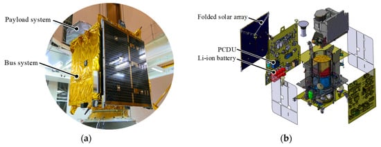
Figure 1.
General structure of the satellite. (a) External structure. (b) Internal structure [10].
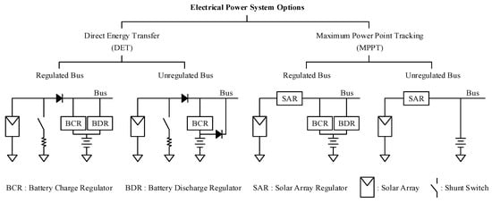
Figure 2.
Categorization of electrical power system configuration of satellite [19].
To reduce the weight and volume of the satellite, the unregulated bus can be employed to create a minimal circuit topology. The bus and output of the solar array are connected directly in the DET type, and any excess energy is dissipated via the shunt switch. The battery is managed using the battery discharge regulator (BDR) and the battery charge regulator (BCR). For geostationary (GEO) satellites with a sufficiently long sun period and enough weight margin for public mission purposes, the DET type is recommended. The MPPT type, on the other hand, employs a solar array regulator (SAR) to take the maximum power from the solar array. As a result, the MPPT type is better suited for commercial low Earth orbit (LEO) satellites with a comparatively short sun period and a small weight margin.
Both the LEO satellite and the GEO satellite must charge the Li-ion battery during the Sun period to complete the electric energy to be used during the eclipse period. The battery’s charge completion is defined as when the end of the charge current reaches the C/50 rate in CV control [39]. For example, in the case of a battery with a capacity of 50 Ah battery, the battery charging completion point is considered when the charging current in the CV control reaches 1 A. Completion of the Li-ion battery charging, when the end of the charge current reaches the C/50 rate in CV control, is required by the space standard [40]. Therefore, manufacturers of satellite Li-ion batteries assume that charging of the Li-ion battery is completed when the end of the charge current reaches the C/50 rate. In addition, since the lifespan of a Li-ion battery is very important to a satellite’s lifespan, it is a rule to complete charging until the end of the charge current reaches the C/50 rate to maximize battery lifespan [41,42]. As illustrated in Figure 3a, the battery charging converter of the MPPT type keeps CV control during the rest sun period after MPPT control. As shown in Figure 3b, since the converter’s output is connected to the battery, the charging process can be finished through the converter’s CV control.
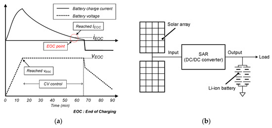
Figure 3.
(a) Battery charging completion point. (b) Configuration of an unregulated bus of the MPPT type.
However, in the case of a regulated bus of the DET type [21,22,23,24,25,26,27,28,29,30,31], since the input of the converter is connected to the battery, there is the problem that the battery charging process cannot be finished through the converter’s CV control. As illustrated in Figure 4, the output of BCR and BDR in the regulated bus of the DET type is connected to the bus, and the bus voltage is regulated through CV control. On the other hand, the inputs of BCR and BDR are connected to the battery. As a result, it is impossible to reduce the battery charging current to the C/50 rate through CV control of the converter output. Therefore, a new strategy is needed to make the end of the charge current reach the C/50 rate for battery charging completion in a regulated bus of the DET type. Thus, in the regulated bus of the DET type, where the battery cannot be charged through CV control of the converter, a tapering charging method is strongly required to reduce the end of the charge current to the C/50 rate.
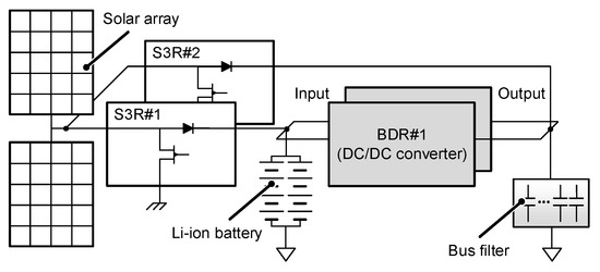
Figure 4.
Configuration of a regulated bus of the DET type.
Various studies have been conducted on algorithms for charging Li-ion batteries [43,44,45]. Ref. [43] shows the potential of Li-ion battery charging methods by introducing a new charging algorithm based on artificial neural networks (ANNs). Ref. [44] shows the simple optimized fuzzy controller responsible for regulating the charging current of a battery charging system. Ref. [45] shows the model predictive control-based charging algorithm for improving the charging time and the average temperature. Through [43,44,45], the lifespan can be improved by enhancing the integrity of the Li-ion battery. However, [43,44,45] is unsuitable as an algorithm for the tapering charging of a satellite’s electrical power system.
In addition, there is no research on an algorithm for tapering charging to be applied to a regulated bus of the DET type of a satellite’s electrical power system.
This paper proposes a Li-ion battery charging control algorithm for a regulated bus of the DET type used in geostationary satellites. The proposed control algorithm controls the BDR current to enable tapering charging of the Li-ion battery. In addition, the proposed control algorithm allows the end of the charge current to decrease to the C/50 rate to complete the battery charging process.
2. Proposed Control Algorithm
This paper targeted an electrical power system for a 3500 kg large-sized geostationary satellite with a mission life of 10 years [10]. Additionally, the 3000 W class satellite’s electrical power system was the focus of this paper.
2.1. Seasonal Characteristics
Since geostationary satellites have eclipses at the equinox but not at the solstice, the proposed control algorithm is designed differently for the equinox and solstice. Figure 5 shows the proposed control algorithm in the equinox, and Figure 6 shows the proposed control algorithm in the solstice. The proposed control algorithm operates with a 0.1 Hz cycle. Table 1 shows variable names that use different values at the equinox and solstice in the proposed control algorithm.
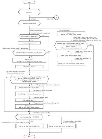
Figure 5.
The proposed control algorithm in the equinox.
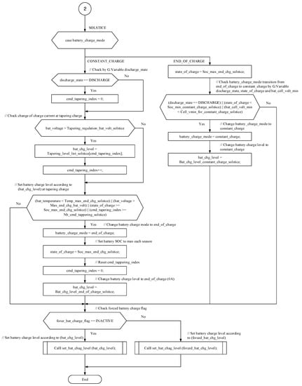
Figure 6.
The proposed control algorithm in the solstice (Corresponds to No. 2 in Figure 5).

Table 1.
Variable names that use different value at the equinox and solstice in the proposed control algorithm.
In the equinox, it charges to a high level to provide enough power in the eclipse for up to 72 min. On the other hand, since the solstice does not use a battery, it only charges up to the storage voltage level of the battery. For this reason, variables in the proposed control algorithm for charging Li-ion battery in the equinox and solstice are managed differently. Table 2 shows the values of variables managed differently in the equinox and solstice. As shown in Table 2, since the eclipse exists during the equinox season, battery charging current, battery charging voltage, battery cell voltage, and battery state of charge (SOC) are relatively higher than solstice. In other words, as shown in Figure 5 and Figure 6, the proposed control algorithm first checks the season when the battery charging control starts and selects the control algorithm suitable for the corresponding season.

Table 2.
Values of variables managed differently in the equinox and solstice.
2.2. Battery Charge Mode
The battery charge mode indicates whether or not the battery is currently charged. The variable battery_charge_mode is used to check the current battery charge mode. There are two battery charge modes: CONSTANT_CHARGE and END_OF_CHARGE. CONSTANT_CHARGE is a mode to charge the battery because the battery is not fully charged. END_OF_CHARGE is a mode to terminate battery charging because the battery is fully charged. As shown in Figure 5 and Figure 6, each battery charging process and charging termination process are followed according to CONSTANT_CHARGE and END_OF_CHARGE modes.
2.3. CONSTANT CHARGE Mode
When entering CONSTANT_CHARGE mode, the battery discharge state is first checked. The variable discharge_state is used to check the current battery discharge state. As shown in Figure 7, the cmd_tapering_index indicates a current index that indicates which battery charge level to set among tapering_level_list_equinox and tapering_level_list_solstice. If the battery is in a discharged state, the cmd_tapering_index is set to 0. It is the initializing process of the cmd_tapering_index. For example, when the cmd_tapering_index is 0, the tapering_level_list_equinox indicates 8.0, and the tapering_level_list_solstice indicates 6.4. If the battery is in a no-discharge state, it passes without initializing the cmd_tapering_index. The cmd_tapering_index is not initialized because the cmd_tapering_index increases according to the tapering charging phase when the battery is in a charged state.
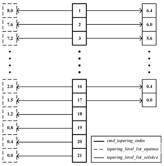
Figure 7.
Correspondence between the value of cmd_tapering_index and the battery charge level of tapering_level_list_equinox and tapering_level_list_solstice.
2.4. Tapering Charging in CONSTANT CHARGE Mode
Tapering charging is a method in which the battery charging current gradually decreases as the charging rate increases. As shown in Figure 3, when the battery is connected to the converter’s output, the charging current can be reduced to iEOC through the CV control of the converter to complete battery charging. However, as shown in Figure 4, in the case of the regulated bus of the DET type configuration, since the battery is connected to the input of the converter, a control other than the converter’s CV control is required to complete battery charging. Therefore, tapering charging that can reduce the charging current to iEOC, even in the regulated bus of the DET type configuration, is proposed.
As illustrated in Figure 8, the battery charging current is calculated by subtracting the current applied to the BDR from the current applied by the sequential switching shunt regulator (S3R) as follows:
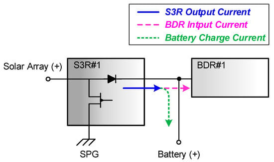
Figure 8.
The flow of S3R output current, BDR input current, and battery charge current in the regulated bus of the DET type.
In other words, sensing the S3R output current and controlling the BDR input current can control the battery charging current setting value.
The variable battery_voltage is used to check the current battery voltage. The variable bat_chg_level is used to check the current battery charge level. If the battery voltage is greater than the value of tapering_regulation_bat_volt_equinox or tapering_regulation_bat_volt_solstice, the battery charge level is applied as the value of tapering_level_list_equinox or tapering_level_list_solstice corresponding to the present cmd_tapering_index. After that, the cmd_tapering_index is increased by 1. In the next cycle, the battery charge level of tapering_regulation_bat_volt_equinox or tapering_regulation_bat_volt_solstice corresponds to the cmd_tapering_index increased by 1 can be applied. In other words, in equinox season, the cmd_tapering_index increases from 0 to 20, decreasing the battery charge level from 8.0 to 0.0 in 21 steps, while in solstice season, the cmd_tapering_index increases from 0 to 16, decreasing the battery charge level from 6.4 to 0.0 in 17 steps, as a tapering charge. In conclusion, the proposed algorithm checks if the battery voltage reaches 40.75 V 21 times in equinox and 39 V 17 times in solstice to perform closed-loop control to proceed or terminate tapering charging.
2.5. Battery Parameters Check in CONSTANT CHARGE Mode
After setting the battery charge level in CONSTAN_CHARGE mode, the steps of checking the current battery temperature, current battery voltage, current battery SOC, and variable cmd_tapering_index are as follows:
The variable bat_temperature is used to check the current battery temperature. Since the battery temperature sensing calibration curve has a negative slope, (2) means that the current battery temperature is higher than temp_max_end_chg_equinox. Because the battery temperature increases as the charging rate increases, tapering charging can be terminated by considering the value of temp_max_end_chg_equinox or temp_max_end_chg_solstice, which is the temperature of the battery at the time of completion of charging. The variable max_end_chg_bat_volt indicates the maximum charging voltage of the battery; (3) means that the current battery voltage is higher than the maximum charging voltage of the battery. The variable state_of_charge is used to check the current SOC of the battery. The current SOC of the battery is calculated as:
Q represents the SOC of the battery, Qmax represents the threshold on SOC for END_OF_CHARGE mode according to the season, Ic represents the battery charging current, Id represents the battery discharging current, and K represents the recharge factor used in the calculation of the battery state of charge, α represents the drift factor (−1 A to 1 A) used in the calculation of the battery state of charge, and ∆t represents the sampling time of the battery charge current and discharge current; (4) means that the current SOC of the battery is higher than the threshold on the SOC for END_OF_CHARGE mode; (5) means that the current command index value exceeds the number of commands value. Therefore, as shown in Figure 5 and Figure 6, if any of the conditions in (2)–(5) are satisfied, the process of terminating tapering charging proceeds.
The process of terminating tapering charging changes the variable battery_charge_mode to END_OF_CHARGE, changes the variable state_of_charge to threshold on the SOC for END_OF_CHARGE mode, initializes the variable cmd_tapering_index to 0, and changes the variable bat_chg_level to battery charge level at END_OF_CHARGE mode.
2.6. END OF CHARGE Mode
In END_OF_CHARGE mode, the variable state_of_charge is changed to the threshold on the SOC for END_OF_CHARGE mode.
2.7. Battery Parameters Check in END OF CHARGE Mode
After setting the current SOC to the threshold on the SOC for END_OF_CHARGE mode, the steps of checking the battery discharge state, battery SOC, and battery cell minimum voltage are as follows:
Equation (7) checks whether the current battery is in a discharged state. When the battery is discharged in END_OF_CHARGE mode, it must be changed back to CONSTANT_CHARGE mode to start tapering charging; (8) means that the current SOC of the battery is lower than the value of soc_min_constant_charge_equinox or soc_min_constant_charge_solstice. This is due to the fact that when the battery is gradually discharged by a small leakage current and reaches the minimum SOC for CONSTANT_CHARGE mode, it must be changed back to CONSTANT_CHARGE mode to start tapering charging. The variable bat_cell_volt_min is used to check the current minimum cell voltage of the battery; (9) means that the current minimum cell voltage of the battery is less than the minimum cell voltage threshold for CONSTANT_CHARGE mode. Therefore, as shown in Figure 5 and Figure 6, if any of the conditions in (7)–(9) are satisfied, the process for performing the tapering charging proceeds.
The process of performing tapering charging changes the variable battery_charge_mode to CONSTANT_CHARGE and changes the variable bat_chg_level to battery charge level at CONSTANT_CHARGE mode.
2.8. Set the Forced Battery Charge Level
Regardless of the control algorithm for tapering charging, it should be possible to charge the battery to a specific charge level through a command from the ground station. The variable force_bat_charge_flag is used to check whether the ground station interrupts the control algorithm for tapering charging to send a command to charge the battery to a specific charge level. The variable forced_bat_charge_level indicates the specific battery charge level set by the ground station. When force_bat_charge_flag is INACTIVE, the battery is charged according to the bat_chg_level set in CONSTANT_CHARGE mode or END_OF_CHARGE mode. In other words, the control algorithm for tapering charging charges the battery regardless of the command from the ground station. However, when force_bat_charge_flag is ACTIVE, the battery is charged according to the forced_bat_chg_level set by the ground station. In conclusion, the control algorithm for tapering charging is designed to charge the battery to a specific charge level by intervening in the ground station at any time.
3. Experimental Results
3.1. Experimental Settings
Figure 9a,b displays the schematic diagram and photograph of the actual configuration of the satellite’s ground electrical test platform. The satellite’s ground electrical test platform includes an onboard computer to which the proposed control algorithm is uploaded and a PCDU to charge the battery by the proposed control algorithm. Figure 10 shows the experimental bench configuration. A solar array simulator that simulates a solar array and supplies power is connected to the PCDU input of the satellite’s ground electrical test platform. The battery to be charged through the proposed control algorithm is connected to the PCDU output of the satellite’s ground electrical test platform. A programmable load simulates a satellite load, and a telemetry monitoring system that monitors key voltages, currents, and modes is connected. Table 3 shows the detailed specifications of the Li-ion battery. As shown in Table 3, the Li-ion battery used in the experiment has a maximum SOC value of 225 Ah and a maximum charging voltage value of 41.4 V. In other words, the experiment was performed with the same electrical configuration as the actual satellite.
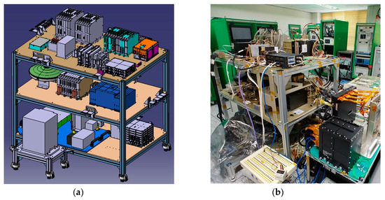
Figure 9.
Satellite’s ground electrical test platform: (a) Schematic diagram. (b) Photograph of the actual configuration.
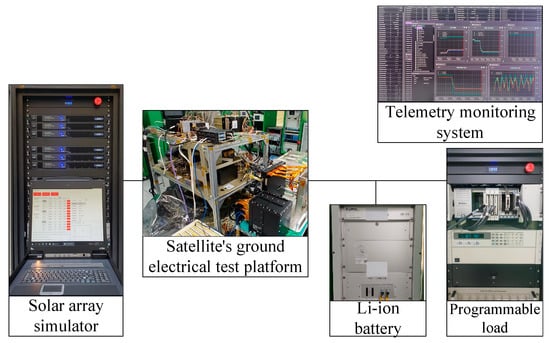
Figure 10.
Experimental bench configuration.

Table 3.
Detailed specifications of the Li-ion battery.
3.2. Experimental Results
Figure 11 shows the experimental results of the battery charging current, cmd_tapering_index, bat_chg_level, and battery_charge_mode until the proposed control algorithm completes tapering charging. As shown in Figure 11, as the battery’s charging rate increases, cmd_tapering_index increases from 0 to 20, and the battery charging current and bat_chg_level decrease from 8.0 to 0.0. As cmd_tapering_index reaches 20, battery_charge_mode changes from CONSTATN_CHARGE mode (‘0′) to END_OF_CHARGE mode (‘1′). This achieves tapering charging in which the battery charge current gradually decreases stepwise, lowering the bat_charge_level as the battery charge rate increases. In other words, the proposed control algorithm confirmed that the tapering charging operation was performed well while the battery charging current and bat_chg_level sequentially decreased according to the designed value according to the increase in cmd_tapering_index. Figure 12 shows the experimental results of battery charging current, cmd_tapering_index, and bat_voltage until the proposed control algorithm completes tapering charging. As shown in Figure 12, when bat_voltage reached 40.75 V, cmd_tapering_index increased by 1, and the battery charging current decreased from 8.0 to 0.0. Thus, when bat_voltage reaches 40.75 V, bat_charge_level decreases. As a result, tapering charging is finished when bat_voltage reaches 40.75 V a total of 21 times. In other words, when the bat_voltage designed in the variable tapering_regulation_bat_volt_equinox reaches 40.75 V, the cmd_tapering_index increases by one step, and the bat_charge_level corresponding to the cmd_tapering_index is set, and as a result, the bat_charge_level gradually decreases. The performance verification of the designed tapering charging control algorithm was completed when battery_charge_mode changed from CONSTATN_CHARGE mode to END_OF_CHARGE mode. The charging method using the proposed control algorithm is applied to the regulated bus of the DET type. Therefore, it is possible to obtain a higher power conversion efficiency of about 99.5% from the solar array to the battery compared to the unregulated bus of the MPPT type that charges the battery through the converter. Additionally, through experiments, it was confirmed that the power conversion efficiency from the solar array to the battery is about 99.5%. This is because there are only diodes in the regulated bus of the DET type’s power path. Figure 11 and Figure 12 are experimental results of the proposed control algorithm in the equinox season. Experimental results in the solstice season are omitted because the same sequence operates in the solstice season.
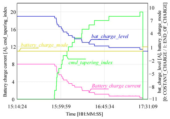
Figure 11.
Experimental results of the battery charging current, cmd_tapering_index, bat_chg_level, and battery_charge_mode until the proposed control algorithm completes tapering charging.
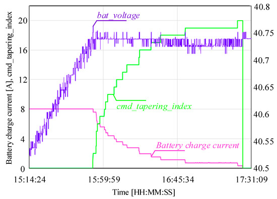
Figure 12.
Experimental results of the battery charging current, cmd_tapering_index, and bat_voltage until the proposed control algorithm completes tapering charging.
4. Conclusions
This paper proposes a control algorithm for tapering charging of the Li-ion battery in geostationary satellites. In the case of a regulated bus of the DET type, the battery charging process cannot be completed through the converter’s CV control because the converter’s input is connected to the battery. To solve this problem, the input current of the BDR is controlled to enable tapering charging of the Li-ion battery. The proposed control algorithm controls by increasing cmd_tapering_index and decreasing bat_charge_level when the bat_voltage reaches a specific value when battery_charge_mode is in CONSTATN_CHARGE mode. Through this, the battery charge current can be gradually reduced until the battery charge current, the battery charging completion point, becomes equal to or less than C/50. In conclusion, the proposed control algorithm can complete the charging process of the Li-ion battery according to each season, even in the regulated bus of the DET type of geostationary satellites.
Funding
This research was supported by the Korea Aerospace Research Institute (KARI), South Korea, under Grant KR23130.
Data Availability Statement
Not applicable.
Conflicts of Interest
The author declares no conflict of interest.
References
- Emrick, R.; Cruz, P.; Carvalho, N.B.; Gao, S.; Quay, R.; Waltereit, P. The Sky’s the Limit: Key Technology and Market Trends in Satellite Communications. IEEE Microw. Mag. 2014, 15, 65–78. [Google Scholar] [CrossRef]
- Satellite Industry Association. State of the Industry Report; Satellite Industry Association: Washington, DC, USA, 2012. [Google Scholar]
- Lepcha, P.; Malmadayalage, T.D.; Örger, N.C.; Purio, M.A.; Duran, F.; Kishimoto, M.; El-Megharbel, H.A.; Cho, M. Assessing the Capacity and Coverage of Satellite IoT for Developing Countries Using a CubeSat. Appl. Sci. 2022, 12, 8623. [Google Scholar] [CrossRef]
- Ruiz-de-Azua, J.A.; Garzaniti, N.; Golkar, A.; Calveras, A.; Camps, A. Towards Federated Satellite Systems and Internet of Satellites: The Federation Deployment Control Protocol. Remote Sens. 2021, 13, 982. [Google Scholar] [CrossRef]
- Grzesik, B.; Baumann, T.; Walter, T.; Flederer, F.; Sittner, F.; Dilger, E.; Gläsner, S.; Kirchler, J.-L.; Tedsen, M.; Montenegro, S.; et al. InnoCube—A Wireless Satellite Platform to Demonstrate Innovative Technologies. Aerospace 2021, 8, 127. [Google Scholar] [CrossRef]
- Gupta, A.; Jha, R.K. A survey of 5G network: Architecture and emerging technologies. IEEE Access 2015, 3, 1206–1232. [Google Scholar] [CrossRef]
- Foust, J. SpaceX’s space-Internet woes: Despite technical glitches, the company plans to launch the first of nearly 12,000 satellites in 2019. IEEE Spectr. 2019, 56, 50–51. [Google Scholar] [CrossRef]
- Harris, M. Tech giants race to build orbital internet. IEEE Spectr. 2018, 55, 10–11. [Google Scholar] [CrossRef]
- Badger, M.; Fujita, A.; Orzel, K.; Hatfield, D.; Kelly, M. Wind Retrieval from Constellations of Small SAR Satellites: Potential for Offshore Wind Resource Assessment. Energies 2023, 16, 3819. [Google Scholar] [CrossRef]
- GEO-KOMPSAT-2 (Geostationary-Korea Multipurpose Satellite-2 Program). Available online: https://www.eoportal.org/satellite-missions/geo-kompsat-2#eop-quick-facts-section (accessed on 16 July 2023).
- Park, J.-E.; Han, J.-K.; Choi, S.-H.; Moon, G.-W. Two-switch forward converter with an integrated buck converter for high bus voltage in satellites. IEEE Trans. Power Electron. 2023, 38, 2041–2051. [Google Scholar] [CrossRef]
- Lim, T.M.; Cramer, A.M.; Lumpp, J.E.; Rawashdeh, S.A. A Modular Electrical Power System Architecture for Small Spacecraft. IEEE Trans. Aerosp. Electron. Syst. 2018, 54, 1832–1849. [Google Scholar] [CrossRef]
- Chen, Y.-K.; Lai, Y.-C.; Lu, W.-C.; Lin, A. Design and Implementation of High Reliability Electrical Power System for 2U NutSat. IEEE Trans. Aerosp. Electron. Syst. 2021, 57, 614–622. [Google Scholar] [CrossRef]
- Fu, M.; Zhang, D.; Li, T. New Electrical Power Supply System for All-Electric Propulsion Spacecraft. IEEE Trans. Aerosp. Electron. Syst. 2017, 53, 2157–2166. [Google Scholar] [CrossRef]
- Nagata, H.; Uno, M. Nonisolated PWM Three-Port Converter Realizing Reduced Circuit Volume for Satellite Electrical Power Systems. IEEE Trans. Aerosp. Electron. Syst. 2020, 56, 3394–3408. [Google Scholar] [CrossRef]
- Park, J.-E.; Han, J.-K.; Park, K.-B.; Lee, B.-H.; Moon, G.-W. A new direct charging control for electrical power systems in low Earth orbit satellites. IEEE Trans. Aerosp. Electron. Syst. 2023, 59, 2566–2578. [Google Scholar] [CrossRef]
- Koo, J.-C.; Park, J.-E.; Moon, G.-W. Triple Junction GAGET2-ID2 Solar Cell Degradation by Solar Proton Events. J. Korean Soc. Aeronaut. Space Sci. 2021, 49, 1019–1025. [Google Scholar]
- Hyder, A.K.; Wiley, R.L.; Halpert; Flood, D.J.; Sabripour, S. Spacecraft Power Technologies; Imperial College Press: London, UK, 2000; ISBN 978-1-86094-117-7. [Google Scholar]
- Kim, D.-K.; Jeong, Y.; Park, J.-E.; Lee, N.; Moon, G.-W. Boost-forward integrated converter for high power density spacecraft applications. In Proceedings of the 2019 10th International Conference on Power Electronics and ECCE Asia (ICPE 2019—ECCE Asia), Busan, Republic of Korea, 27–30 May 2019; pp. 1–6. [Google Scholar]
- Zhang, X.; Kang, Q.; Yu, W.; Xing, J.; Li, F.; You, X. Power Assessment Indices of Solar Arrays under MPPT and DET methods for Spacecraft. In Proceedings of the 2019 European Space Power Conference (ESPC), Juan-les-Pins, France, 30 September–4 October 2019; pp. 1–4. [Google Scholar]
- Weinberg, A.; Schreuders, J. A high-power high-voltage DC-DC converter for space application. IEEE Trans. Power Electron. 1986, PE-1, 148–160. [Google Scholar] [CrossRef]
- Weinberg, A.; Ghislanzoni, L. A new zero voltage and zero current power-switching technique. IEEE Trans. Power Electron. 1992, 7, 655–665. [Google Scholar] [CrossRef]
- Zhu, H.; Zhang, D. Design Considerations of Sequential Switching Shunt Regulator for High-Power Applications. IEEE Trans. Ind. Electron. 2020, 67, 9358–9369. [Google Scholar] [CrossRef]
- Sanchis, E.; Maset, E.; Ferreres, A.; Ejea, J.B.; Esteve, V.; Jordán, J.; Garrigós, A.; Blanes, J.M. High-power battery discharge regulator for space application. IEEE Trans. Ind. Electron. 2010, 57, 3935–3943. [Google Scholar] [CrossRef]
- Weinberg, A.; Boldo, P.R. A high power, high frequency, DC to DC converter for space applications. In Proceedings of the IEEE 23rd Annual IEEE Power Electronics Specialists Conference, Toledo, Spain, 29 June–3 July 1992; pp. 1140–1147. [Google Scholar]
- Blanes, J.M.; Carrasco, J.A.; Garrigós, A.; Marroquí, D.; Torres, C. Sequential Switching Shunt Regulator Parallel Power Processing Control for High Capacitance Solar Arrays. Energies 2021, 14, 429. [Google Scholar] [CrossRef]
- Ejea, J.B.; Ferreres, A.; Sanchis-Kilders, E.; Maset, E.; Esteve, V.; Jordan, J.; Garrigos, A. Optimized topology for high efficiency battery discharge regulator. IEEE Trans. Aerosp. Electron. Syst. 2008, 44, 1511–1521. [Google Scholar] [CrossRef]
- Bae, J.-H.; Park, J.-E.; Lee, J.-Y.; Lee, N.; Han, S.-K. An improved weinberg converter with low output current and voltage ripple. In Proceedings of the IECON 2019—45th Annual Conference of the IEEE Industrial Electronics Society, Lisbon, Portugal, 14–17 October 2019; pp. 1597–1602. [Google Scholar]
- DKim, K.; Jeong, Y.; Baek, J.-I.; Park, J.-E.; Lim, C.-W.; Moon, G.-W. High efficiency and high power density weinberg converter reducing conduction loss and output current ripple for space applications. In Proceedings of the 2019 IEEE Applied Power Electronics Conference and Exposition (APEC), Anaheim, CA, USA, 17–21 March 2019; pp. 1583–1586. [Google Scholar]
- Bae, J.-H.; Park, J.-E.; Han, S.-K. A Battery Discharge Regulator with a Low-Output Current Ripple of an Electrical Power System in a Geostationary Satellite. IEEE Access 2023, 11, 58099–58112. [Google Scholar] [CrossRef]
- Park, J.-E.; Lee, N.; Choi, J.-D.; Jang, J.B.; Lee, S.-R. Dc-dc Converter. U.S. Patent US20190173385A1, 6 June 2019. [Google Scholar]
- Garrigós, A.; Blanes, J.M.; Lizán, J.L.; Carrasco, J.A.; Sanchis-Kilders, E.; Maset, E.; Ejea, J.B. Hydrogen back-up power system with photovoltaic direct energy transfer regulation and interleaved boost for space applications. In Proceedings of the 27th Annual IEEE Applied Power Electronics Conference and Exposition (APEC), Orlando, FL, USA, 5–9 February 2012; pp. 690–696. [Google Scholar]
- Mourra, O.; Fernandez, A.; Tonicello, F. Buck Boost Regulator (B2R) for spacecraft Solar Array Power conversion. In Proceedings of the 2010 Twenty-Fifth Annual IEEE Applied Power Electronics Conference and Exposition (APEC), Palm Springs, CA, USA, 21–25 February 2010; pp. 1313–1319. [Google Scholar]
- Qian, Z.; Abdel-Rahman, O.; Al-Atrash, H.; Batarseh, I. Modeling and Control of Three-Port DC/DC Converter Interface for Satellite Applications. IEEE Trans. Power Electron. 2010, 25, 637–649. [Google Scholar] [CrossRef]
- Schirone, L.; Ferrara, M.; Granello, P.; Paris, C.; Pellitteri, F. Power Bus Management Techniques for Space Missions in Low Earth Orbit. Energies 2021, 14, 7932. [Google Scholar] [CrossRef]
- Carrasco, J.A.; de Quirós, F.G.; Alavés, H.; Navalón, M. An analog maximum power point tracker with pulse width modulator multiplication for a solar array regulator. IEEE Trans. Power Electron. 2019, 34, 8808–8815. [Google Scholar] [CrossRef]
- Selcan, D.; Kirbis, G.; Kramberger, I. Analog maximum power point tracking for spacecraft within a low earth orbit. IEEE Trans. Aerosp. Electron. Syst. 2016, 52, 368–378. [Google Scholar] [CrossRef]
- Ali, A.J.; Khalily, M.; Sattarzadeh, A.; Massoud, A.; Hasna, M.O.; Khattab, T.; Yurduseven, O.; Tafazolli, R. Power Budgeting of LEO Satellites: An Electrical Power System Design for 5G Missions. IEEE Access 2021, 9, 113258–113269. [Google Scholar] [CrossRef]
- McKissock, B.; Loyselle, P.; Vogel, E.; NASA aerospace flight battery program. In NASA Engineering and Safety Center Technical Report; 2008; Volume 2. Available online: https://www.nasa.gov/pdf/287383main_RP-08-75%2006-069-I%20NASA%20Aerospace%20Flight%20Battery%20Program%20_Part%20I-Volume%20II_FINAL_7-10-08_.pdf (accessed on 16 July 2023).
- ECSS-E-ST-20C; Space Engineering Electrical and Electronic. European Cooperation for Space Standardization: Noordwijk, The Netherlands, 2008.
- Barnara, M.; Patricia, L.; Elisa, V. Guidelines on Lithium-Ion Battery Use in Space Applications; NASA TM-2009-215751. 2009. Available online: https://ntrs.nasa.gov/api/citations/20090023862/downloads/20090023862.pdf (accessed on 16 July 2023).
- Charging Your Lithium-Ion Batteries: 5 Expert Tips for a Longer Lifespan (SAFT). Available online: https://www.saft.com/energizing-iot/charging-your-lithium-ion-batteries-5-expert-tips-longer-lifespan (accessed on 16 July 2023).
- Faria, J.P.D.; Velho, R.L.; Calado, M.R.A.; Pombo, J.A.N.; Fermeiro, J.B.L.; Mariano, S.J.P.S. A New Charging Algorithm for Li-Ion Battery Packs Based on Artificial Neural Networks. Batteries 2022, 8, 18. [Google Scholar] [CrossRef]
- Károlyi, G.; Pózna, A.I.; Hangos, K.M.; Magyar, A. An Optimized Fuzzy Controlled Charging System for Lithium-Ion Batteries Using a Genetic Algorithm. Energies 2022, 15, 481. [Google Scholar] [CrossRef]
- Chen, G.-J.; Liu, Y.-H.; Cheng, Y.-S.; Pai, H.-Y. A Novel Optimal Charging Algorithm for Lithium-Ion Batteries Based on Model Predictive Control. Energies 2021, 14, 2238. [Google Scholar] [CrossRef]
Disclaimer/Publisher’s Note: The statements, opinions and data contained in all publications are solely those of the individual author(s) and contributor(s) and not of MDPI and/or the editor(s). MDPI and/or the editor(s) disclaim responsibility for any injury to people or property resulting from any ideas, methods, instructions or products referred to in the content. |
© 2023 by the author. Licensee MDPI, Basel, Switzerland. This article is an open access article distributed under the terms and conditions of the Creative Commons Attribution (CC BY) license (https://creativecommons.org/licenses/by/4.0/).