Review

Recent Achievements in the Control of Interior Permanent-Magnet Synchronous Machine Drives: A Comprehensive Overview of the State of the Art

by
Peter Stumpf
*,† and
Tamás Tóth-Katona
Department of Automation and Applied Informatics, Budapest University of Technology and Economics, Muegyetem Rkp. 3., H-1111 Budapest, Hungary
*
Author to whom correspondence should be addressed.
These authors contributed equally to this work.
Energies 2023, 16(13), 5103; https://doi.org/10.3390/en16135103
Submission received: 29 May 2023 / Revised: 24 June 2023 / Accepted: 27 June 2023 / Published: 1 July 2023
(This article belongs to the Topic Future Generation Electric Machines and Drives)

Abstract

:
Interior permanent-magnet synchronous machines (IPMSMs) are widely used as traction motors in electric drive-trains because of their high torque-per-ampere characteristics and potential for wide field-weakening operations to expand the constant-power range. This paper offers a categorization and a comprehensive overview of the control techniques applied to IPMSM drives in addition to presenting the necessary theoretical background. The basic concept, features and limitations, as well as the latest developments of the strategies, are summarized in the paper. This overview helps to lay the theoretical basis as well as to clarify the opportunities, challenges and future trends for controlling IPMSM drives for traction applications.

1. Introduction

In recent years and in the near foreseeable future, the global trend for the electrification of drivelines in the automotive industry shows a dynamic upward trend. The appearance of mild-hybrid and full-electric vehicles (EV) as well as micromobility vehicles on roads is increasing. This plays an important role in the reduction of greenhouse gas emissions. Most commonly, induction machines and permanent-magnet synchronous machines (PMSM) are used for EVs, but the role of synchronous reluctance machine (SynRM) drives have also increased recently. However, market trends show that PMSMs are still dominant in traction drives due to inherent advantages like high efficiency and power density, maturity and robustness [1]. Interior PMSM (IPMSM) machines also offer the possibility of a wide-speed operating range, which is an attractive property for EVs.
To exploit the inherent potential of IPMSM machines, an appropriate control strategy is essential. The primary purpose of this article is to present and categorize the different control strategies. Although the main focus of this paper is traction drives, the methods presented here can be used in other applications.
To cover most of the topics related to the control of IPMSM drives, the paper is organized as follows:
  • Section 2 lays down the necessary theoretical background. This section presents the construction, the mathematical modeling and the operating regions of IPMSMs. Furthermore, it gives a short overview about voltage source inverters. The section also presents the recent trends for the given field.
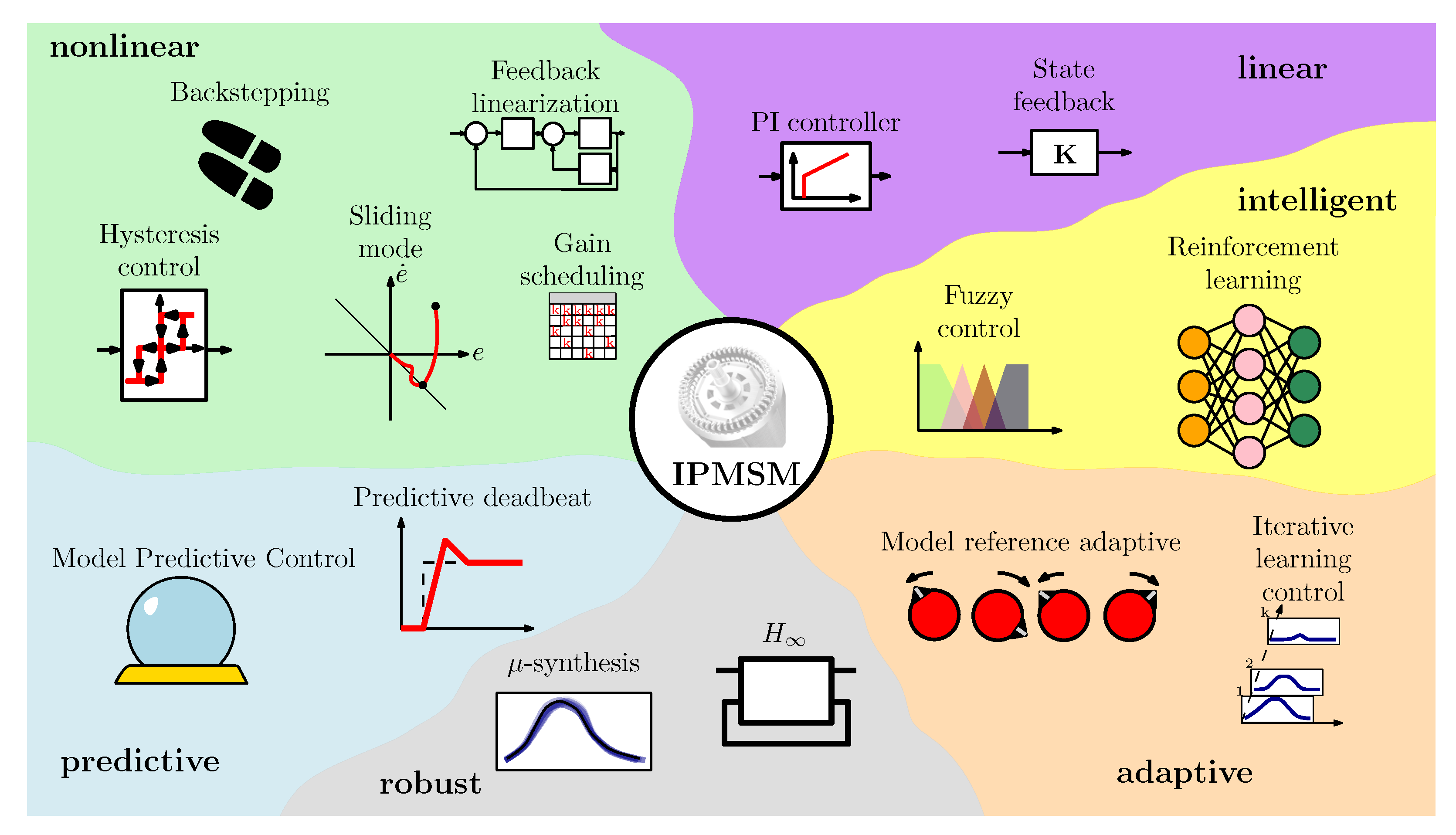
  • Section 3 evaluates the different control approaches used for IPMSM drives, which have been grouped as linear, nonlinear, predictive, robust, intelligent and adaptive.
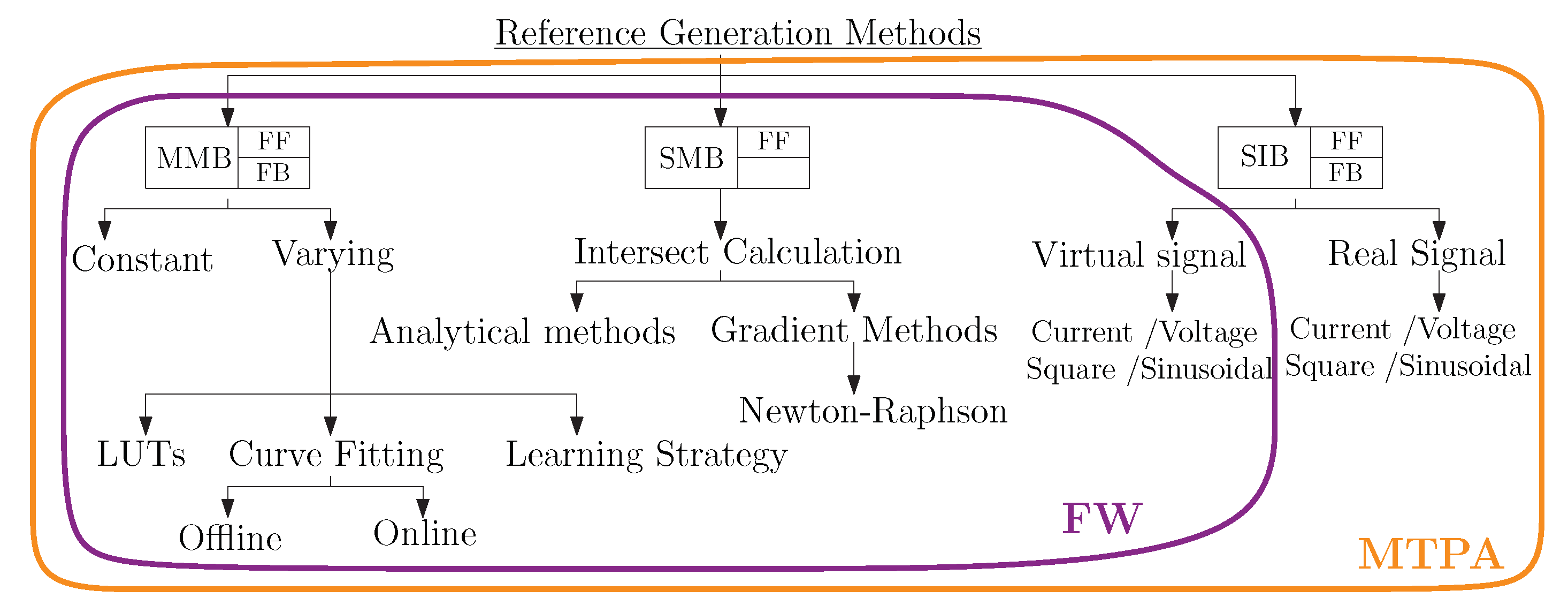
  • Section 4 offers a brief overview about different reference signal generation techniques in the constant-torque and the field-weakening regions.
  • Section 5 concludes the article and summarizes future trends and challenges.

2. Theoretical Background
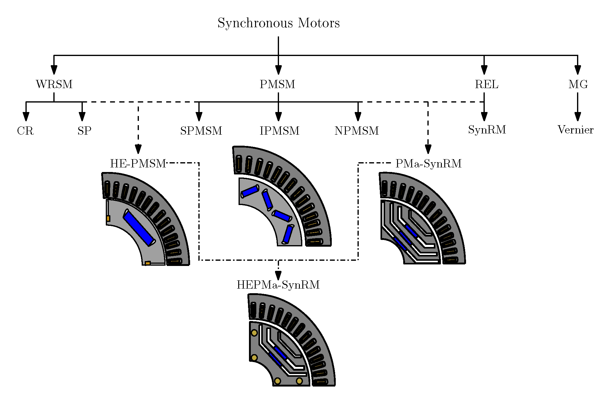
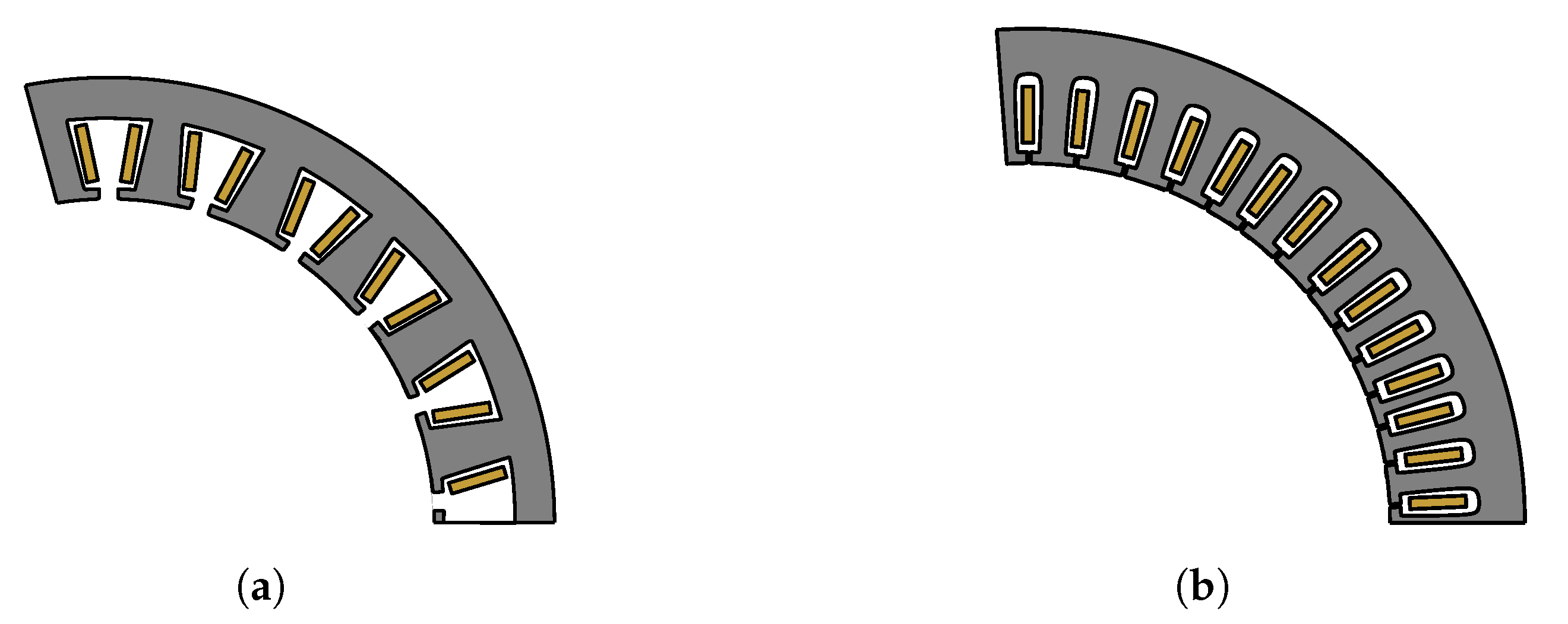
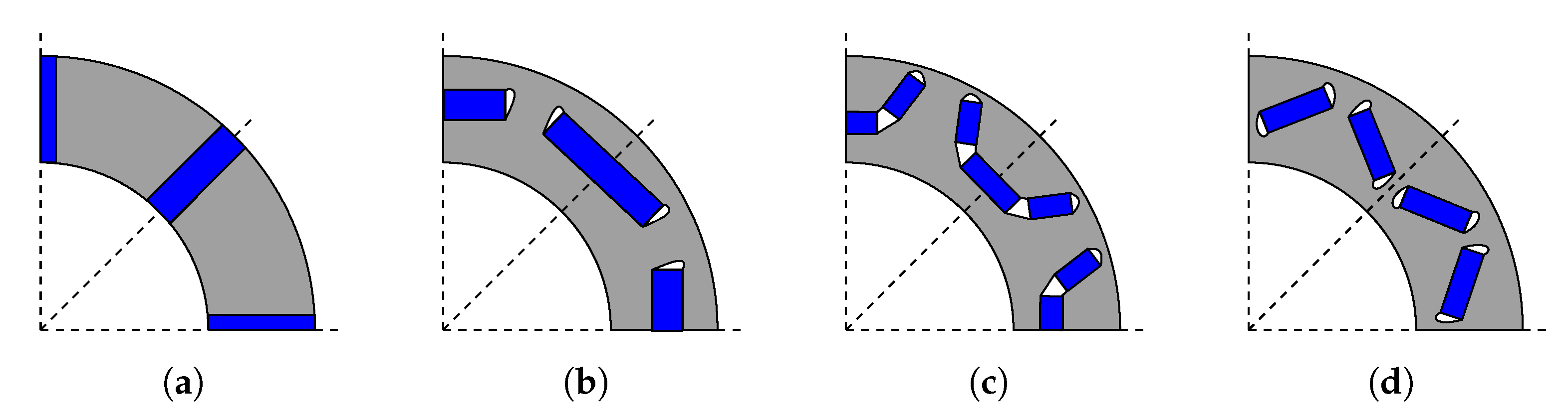
2.1. Construction

Figure 1 collects the different types of SMs developed and investigated in recent years. According to the figure, SMs can be categorized into four main groups. The first group is the wound rotor SM (WRSM), of which two types, the cylindrical rotor (CR) and salient pole (SP) rotor, can be distinguished. The feasibility of WRSM construction for traction application is presented in [2]. The paper introduces a design methodology and shows that WRSMs can have better efficiency under low load conditions than SMs with permanent magnets. Synchronous reluctance machines (SynRM) belong to the second group (see Figure 1). Paper [3] offers a detailed overview of the design methodologies, recent advancements and challenges of SynRMs. The third group consists of permanent-magnet synchronous motors (PMSM). This category contains the interior permanent-magnet SM (IPMSM) [4], surface-mounted permanent-magnet SM (SPMSM) and normal-saliency permanent-magnet SM (NSPMSM) [5]. Finally, the fourth group contains magnetically geared (MG) machines [6], with a particular interest in Vernier machines [7].
Recently, increasing attention has been paid to hybrid design motors with the possibility to combine the advantages of the three different groups. Paper [8] demonstrates the potential of hybrid-excited PMSMs (HE-PMSM), which aim to merge the advantages of both the high PM flux excitation and the possibility of controlling the rotor flux through rotor-winding currents. The permanent-magnet-assisted SynRM (PMa-SynRM) aims to combine the PM motor and the reluctance motor construction [9]. The main goal behind these hybrid machine designs is usually to reduce costs, either by reducing the amount of rare-earth (RE) PMs used or by improving the efficiency. These two hybrid designs are highlighted in this paper, as they can produce similar efficiency and performance in the same operation ranges as the benchmark IPMSM designs, which are typically the IPMSM used either in the Toyota Prius 2010 or in the BMW I3 [2]. Even more topology combinations are plausible, as shown in [10], where a combination of all three topologies (HEPMa-SynRM) was investigated. In paper [11], a hybrid-excited SynRM was investigated (HE-SynRM) without PMs.
It can be concluded that although the results of novel SM constructions are promising, IPMSMs are still the most dominant machine topology for EV/HEV traction applications due to its favorable torque density, lighter weight, more compact packaging and better constant-power speed range.
The performance of an IPMSM can be also improved by optimizing the geometrical parameters and the used materials of the machine. Two directions can be distinguished in these efforts: optimization of the stator and/or the rotor.
In general, stator winding of IPMSMs can be separated either to fractional-slot concentrated winding (FSCW) or integer-slot distributed winding (ISDW) (see Figure 2). IPMSMs having FSCW have the advantage of lower copper losses, smaller torque ripple and favorable flux capability compared to ISDW machines [12]. ISDW machines have the advantage of a lower level of space harmonics and fewer eddy current losses, and therefore, better high-speed performance. Furthermore, they offer a lower level of cogging torque [13]. A characteristic of FSCW machines is their larger space harmonics; this causes excess losses, vibration and noise compared to ISDW machines. To reduce the space harmonics, a widely utilized solution is to wound the rotor using a star–delta winding [14]. However, in the delta section of the star–delta winding,a circulating current occurs. This phenomenon is undesirable, as it leads to higher losses and possible demagnetization of the motor. A novel design methodology for an asymmetric star–delta winding to reduce the effect of circulating current is introduced in [14]. Also, an asymmetric star–delta winding is proposed in [15] to reduce the electromagnetic vibrations caused by the electromagnetic forces acting on the stator teeth and/or magnets.
The stator winding itself can be in the form of either stranded or bar conductors. Bar conductors, also called hairpins, have lower DC resistance and better fill factor, thermal performance, fault tolerance and cooling options compared to machines with stranded winding. However, due to the skin effect and higher AC resistance, the power drops in high-speed regions. Furthermore, bar conductors suffer from uneven winding losses, which can lead to local thermal problems. To overcome the latter problem, the typical solution is to use multiple conductors per slot and to connect the airgap side conductors to the slot-end side conductors. Paper [16] proposes a so-called asymmetric bar winding for high-speed traction electric machines to reduce AC losses at high speeds. The name of asymmmetric bar winding comes from the idea to change the cross section of the winding within the stator slots.
The optimization of rotor construction is multifold. Numerous optimization targets of the motor can be chosen. These could be the shape, the orientation, the number of layers or the materials of the magnets within the rotor. Other optimization targets within the rotor could be the length or shape of flux barriers. Furthermore, the rotor surface can be optimized using surface indents. While multiple options are possible, there is some consensus in the scientific literature regarding the geometric design of IPMSM rotors. Paper [17] offers a comparative study of different rotor topologies of IPMSMs. In the paper, four commonly used topologies (see Figure 3), namely spoke-type, tangential type, U-type and V-type, were compared by using finite element methods. The naming convention of these rotor topologies hints at the orientation of the rotor magnets. The paper finds square-shaped magnets and the minimization of the magnet layer number optimal for rotor design. Furthermore, the authors concluded that V-type rotors are favorable due to their better overall performance along the complete operation range of the IPMSM.
RE magnets exhibit high conductivity; thus, magnetic eddy current loss becomes relevant in high-speed operations. This is especially the case for FSCW-IPMSM machines [18]. According to [18], magnetic eddy current losses are reduced the most when the rotor magnets are oriented in a V-type topology. The high level of eddy current loss can cause demagnetization in the deep field-weakening region. To alleviate this issue, many IPMSM rotor structures incorporate dysprosium (Dy). The hectic price and the uncertainty of the supply line of RE materials, like NdFeB, Sm-Co and Dy, feed new research directions to utilize non-RE magnets, like ferrite, in the rotor structure [19]. Paper [20] investigated a new hybrid rotor structure with reduced magnetic eddy current losses by changing the PM materials from RE magnets to ferrite magnets in some segments of a two-layered hybrid U-shape and tangential topology rotor. The authors of Paper [20] introduced a V-type rotor structure for high-speed application in [12] by utilizing ferrite and NdFeB magnets and optimizing the angle of the V-oriented magnets.
A rotor surface modification optimization was carried out for a V-type rotor topology in [21]. The main objectives were high torque capacity and low torque ripple. These aims were targeted to lessen the extra vibration and noise of IPMSM machines. In paper [22], the magnet arrangement of a multilayered rotor is performed to improve electromagnetic performance. The authors proposed a novel method by placing some PMs close to the rotor surface and using a magnetic bridge between these smaller magnets and the larger, deeper, buried magnets.
In summary, it can be concluded that IPMSMs with V-type rotor construction are most favorable for traction drives due to their advantages. From a materials point of view, there is a clear trend to find alternatives to RE materials to reduce costs and to improve efficiency in high-speed applications. Optimizing the angle of the magnet and the geometric parameters of flux barriers and magnet bridges seem to be fruitful endeavors. Furthermore, newer optimization methodologies based on genetic algorithm and finite element simulations used in tandem with surrogate models are constantly improving in simulation speed and optimization results.

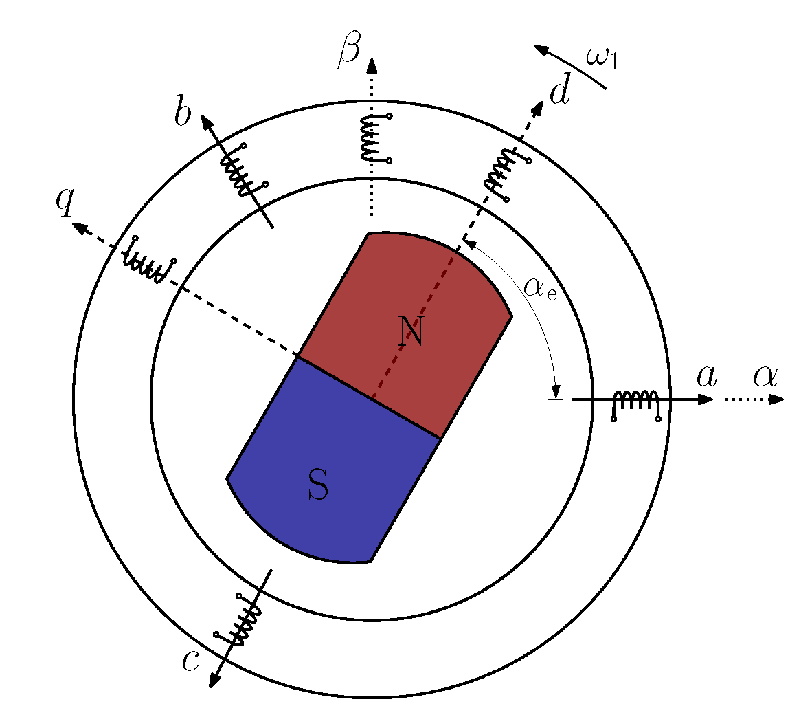
2.2. Mathematical Model of IPMSM

The stator windings of a three-phase IPMSM are supplied by three phase voltages: v a , v b and v c , which result in phase currents i a , i b and i c . The voltage equations for the stator windings can be expressed as
v a v b v c = R s i a i b i c + d d t i a i b i c L sa L mab L mac L mba L sb L mbc L mca L mcb L sc + Ψ PM cos ( α e ) cos ( α e 2 π / 3 ) cos ( α e + 2 π / 3 ) ,
where R s is the per-phase stator resistance, assuming that the windings are symmetric; Ψ PM is the amplitude of the flux induced by the permanent magnets of the rotor in the stator phases; and α e = n p α m is the electrical angle of the machine (see Figure 4), where n p is the number of pole pairs and α m is the mechanical angle of the rotor. Furthermore, L mxy represents the mutual inductance between two phases and L sx denotes the self-inductance of the given phase.
In the case of IPMSMs, due to the rotor saliency, the effective air gap is not uniform around the circumference of the rotor. Therefore, the self- and mutual inductances are a function of the rotor position. Self-inductances can be given as [23]
L sa = L ls + L A + L B cos ( 2 α e ) L sb = L ls + L A + L B cos ( 2 α e 2 π / 3 ) L sc = L ls + L A + L B cos ( 2 α e + 2 π / 3 ) ,
where L ls is the leakage inductance. L A and L B can be determined from the number of turns of the windings, the radius of the stator, the axial length of the air gap and the minimum and maximum air gap length, according to [23]. Mutual inductances can be expressed as
L mab = L mba = 1 2 L A L B cos ( 2 α e 2 π / 3 ) L mac = L mca = 1 2 L A L B cos ( 2 α e + 2 π / 3 ) L mbc = L mcb = 1 2 L A L B cos ( 2 α e )
To eliminate the position dependency of inductance values and simplify the mathematical representation of the IPMSM, all the quantities given in the abc axes should be transformed first to an α - β stationary reference frame (SRF), and after, to a d-q rotating reference frame (RRF) (see Figure 4).
The so-called Clarke transformation can be used to transform the abc phase quantities to the α - β SRF:
x α x β = 2 3 1 1 2 1 2 0 3 2 3 2 x a x b x c
The quantities in the d-q RRF can be obtained with the help of the so-called Park transformation:
x d x q = cos ( α e ) sin ( α e ) sin ( α e ) cos ( α e ) x α x β
Thanks to the Park transformation, the d axis aligns with the rotor magnetic flux, which eliminates the position dependency of the inductance values.
The resulting equations of the IPMSM in the d-q RRF can be given as
v d = R s i d + L d d i d d t ω 1 L q i q v q = R s i q + L q d i q d t + ω 1 L d i d + ω 1 Ψ PM
where ω 1 = d α e d t = n p Ω is the electrical angular frequency and Ω is the mechanical angular speed of the machine. When utilizing a voltage source inverter (VSI) to feed the IPMSM, the control option is the voltage vector v = [ v d v q ] T in RRF that the VSI can produce by using a proper modulation scheme.
The equations of stator flux in the d and q axes are given as follows:
Ψ d = L d i d + Ψ PM Ψ q = L q i q
The d and q axis inductance can be also expressed as [24]
L d = L ls + 3 2 ( L A L B ) L q = L ls + 3 2 ( L A + L B )
The M electric torque of the machine can be given as
M = 3 2 P Ψ PM i q + ( L d L q ) i d i q
The dynamic equation for the mechanical speed of the machine is
d Ω d t = 1 J ( M M load B Ω ) ,
where J is the inertia of the drive system, M load is the loading torque and B is the viscous damping.
It should be noted that the machine parameters given in the equations above are not constant. The permanent magnet flux Ψ PM as well as the L d and L q inductances are highly dependent on the i d and i q currents [25] as well as the temperature [26,27], rotor angle [28,29] and current angle [30]. Typically, to keep the complexity of the model within reasonable limits, only the current dependencies are taken into account during the control of the machine, since their effect is the most significant [31]. An improved d-q model for IPMSMs, where the effect of harmonic inductances as well as saturation and cross-saturation was taken into account, is introduced in [32]. The model presented in [29] also takes into account the effect of spatial harmonics and magnetic saturation near the effect of the rotor position. Paper [26] presents the inductance variation as a function of the temperature. An improved high-fidelity IPMSM mathematical model, verified by the finite element model, including saturation, cross-coupling and torque ripple, is introduced in [33]. A generalized machine model in RRF, which takes into account multiple saliencies, and a technique to obtain the position-dependent inductances, are proposed in [34]. The modeling of saturation and spatial harmonics using ANSYS Maxwell and Matlab Simulink software packages is introduced in [35].
The R s stator resistance may also depend on the temperature as well as on the current and electrical frequency due to the skin and proximity effects [30,36]. Paper [36] takes into account the effect of the stator iron resistance in the mathematical model of the IPMSM for a more accurate control of the machine. The IPMSM models introduced in [29,33] also model the effect of the iron losses.
The current dependency of the motor parameters results that the electric torque of the machine is a highly nonlinear function of i d and i q . Therefore, as it will be discussed in Section 4, special care should be given to generate the reference signals for the current or torque and flux control loops.

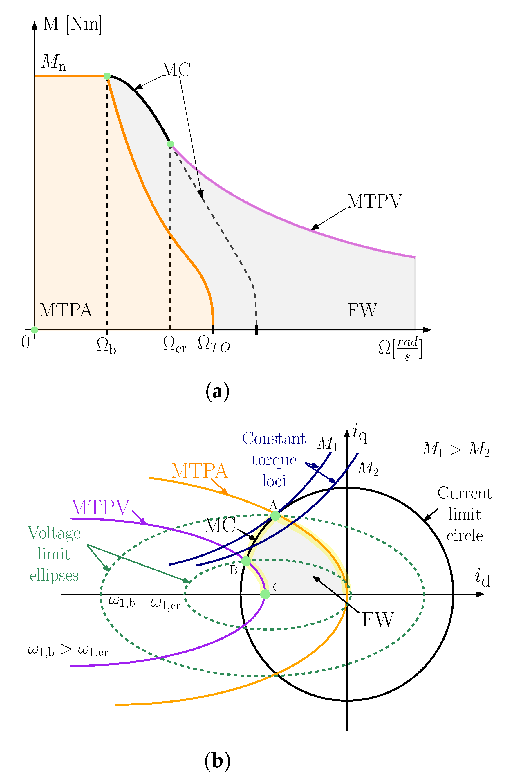
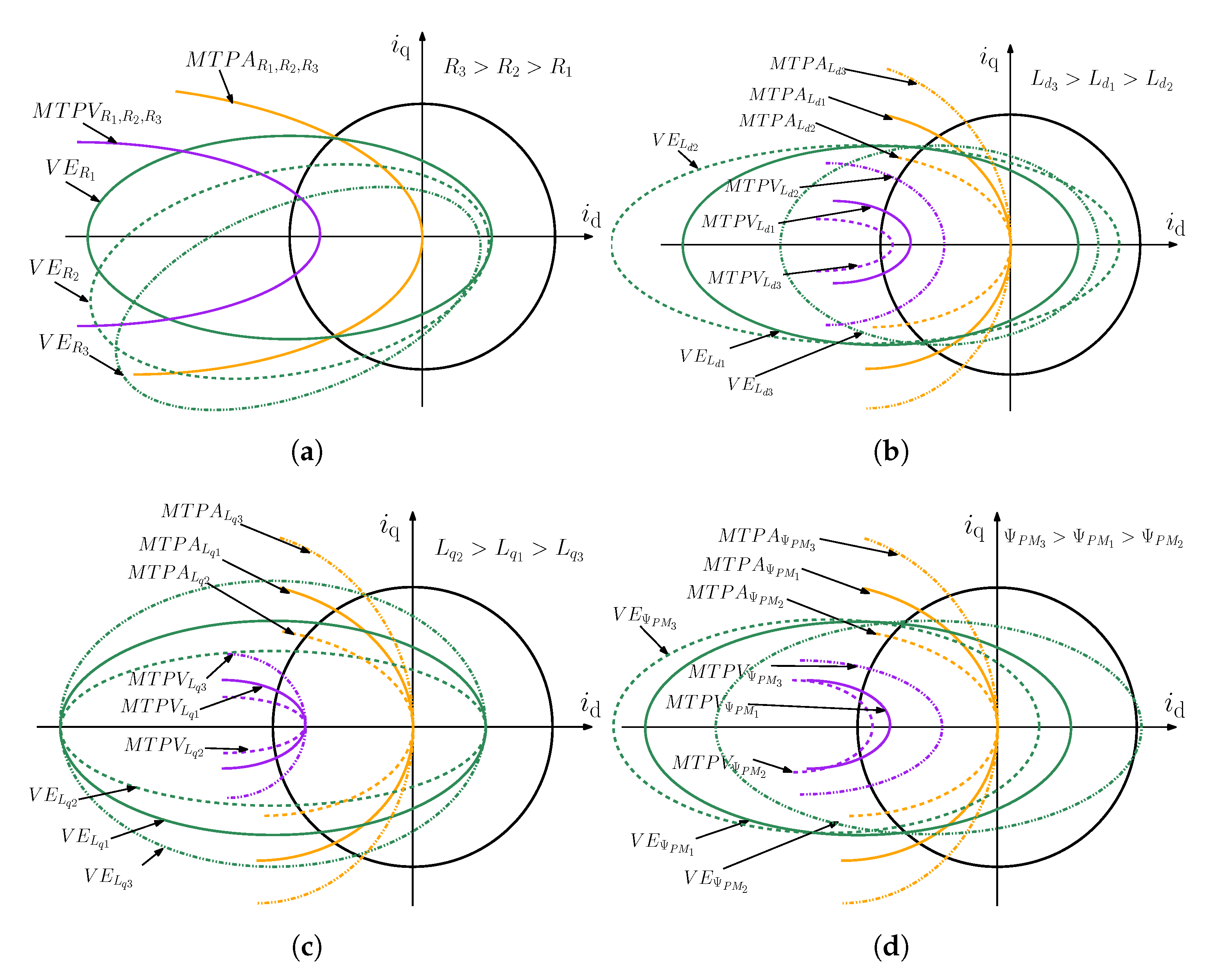
2.3. Operation Regions

In general, IPMSMs utilized in traction drives or in other field applications require constant torque performance at low speed and a constant power at higher speeds. The operating regions of the machine as the functions of mechanical speed Ω = n p ω 1 and electric torque M are illustrated in Figure 5a. In the constant-torque region, the nominal torque M n cannot be exceeded permanently. Above the base speed denoted by Ω b = ω 1 , b / n p , the output torque of the machine must be reduced as the mechanical speed increases. Typically, the base speed is the nominal speed, where the machine is supplied by its nominal voltage [37]. The constant-power part of the torque–speed curve is also called the field (or flux)-weakening (FW) region, since here, the magnitude of the stator flux drops below its nominal value as the voltage is kept constant and the electrical angular frequency increases.
In the case of an electric drive, the current and voltage constraints determined by the machine itself and/or the VSI feeding it (see next section) must be taken into account. Most commonly in the literature, the maximum allowable current I s , max and maximum output voltage V s , max of the drive-train are equated to the maximum stator current and stator voltage. Therefore, the electric constraints along the operation regions in the dq frame can be written as
i s = | i | = i d 2 + i q 2 I s , max and v s = | v | = v d 2 + v q 2 V s , max ,
where v s and i s denote the momentary amplitude of the stator voltage and the current of the machine, respectively. Typically, I s , max and V s , max are selected to be the rated current and voltage of the machine, respectively. However, it can happen that the VSI limits the maximum voltage below the rated voltage of the machine, for example, in the case of lower DC bus voltages.
While it is not strictly an electric constraint, expressing the momentary magnitude of the stator flux Ψ s in a similar form to the electric constraints is handy for describing the different operation regions. By neglecting the stator resistance R s , it can be written as
Ψ s = Ψ d 2 + Ψ q 2 = ( L d i d + Ψ PM ) 2 + Ψ q 2 V s , max ω 1
To represent the operation regions of an IPMSM, another widely used approach is to present the working points of the machine on the i d - i q plane, as can be seen in Figure 5b. In such a plane, the constant-current loci are circles, the constant-flux-linkage loci are ellipses and the constant-torque loci are hyperbolas. In the i d - i q plane, the maximum allowable current and voltage can be expressed by a current limit circle and a voltage limit ellipse, respectively. It should be noted that in the latter case, the length of the axes of the ellipse is inversely proportional to the actual electrical angular frequency ω 1 (see Figure 5b). The machine should be operated in a working point, which is inside the boundaries determined by both the current limit circle and the voltage limit ellipse.
Efficiency is one of the most important aspects of modern electric drives. An extensive number of papers have been published in the literature on how to control IPMSMs to obtain maximum efficiency. Paper [38] offers a detailed overview about the different techniques of how to generate the optimal reference signals for the current or the torque/flux loop. In general, the operating regions that maximize efficiency can be divided in to four regions: maximum torque per ampere (MTPA), which is equivalent to the commonly named maximum torque per current region (MTPC); field weakening (FW); maximum current (MC); and maximum torque per voltage (MTPV). These four regions are denoted in Figure 5a,b. It should be noted that the MC and MPTV regions are actually part of the FW region, but in these regions, the drive operates at its voltage and current limits (MC) or at its voltage limit (MPTV).
The MTPA (MPTC) strategy aims to minimize copper losses in the constant-torque region (see Figure 5a). The MTPA method has been deeply investigated in several papers [38,39,40] (see later Section 4). Therefore, many different mathematical derivations of the optimal trajectory in the i d - i q plane have been introduced over the past few decades. The MTPA trajectory, where the ratio of torque and current is maximized for any operating condition, can be found by searching for the minimum of the function of the electric torque expressed with the help of the d and q axis current components. The MPTA trajectory can be seen in Figure 5b. It should be noted that this trajectory corresponds to the tangent points of the constant-torque loci and constant-current circles. In a steady state, the endpoint of the MTPA trajectory is determined by the intersection point of the current limit circle and the voltage ellipse circle at the base angular frequency ω 1 , b = n p Ω b (see Figure 5a and point A in Figure 5b). It should be noted at this point that the machine operates both at V s , max and I s , max .
To operate the machine at its current and voltage limit at increasing mechanical speed, the MC strategy can be used to obtain the maximally feasible torque. The optimal current trajectory can be acquired on the i d - i q plane by determining the the intersection points of the current limit circle and the voltage limit ellipses at different angular velocities (see Figure 5b). In this region, i d increases toward a negative direction and i q decreases. The theoretical maximum speed belongs to the working point when i d = I s , max and i q = 0 . The magnitude of the stator flux at this point can be expressed from (7) as Ψ s , min = Ψ PM L d i d = Ψ PM L d I s , max . Assuming that Ψ s , min is positive ( Ψ PM > L d I s , max ), the mechanical speed belonging to this point can be estimated by using (12) as Ω max = V s , max / ( Ψ s , min n p ) . At this speed, both the torque and the power of the machine are zero.
If Ψ PM < L d i d , then the center point of the voltage limit ellipse can be found inside the current limit circle, as shown in Figure 5b. For this situation, the current vector trajectory moves along the current limit circle only up to the critical speed Ω c r = n p ω 1 , c r (see Figure 5a and points B in Figure 5b). At this speed, the current limit circle intersects the voltage limit circle belonging to ω c r . Above Ω c r , the machine is operated at the so-called MTPV trajectory. The MTPV curve, where the ratio of torque and voltage is maximized, can be found by searching for the minimum of the function of the electric torque expressed with the help of d and q axis flux components from the voltage constraint. The MTPV trajectory on the i d - i q plane is formed by the intersection points of the constant-torque loci and the voltage limit circles. As can be seen in Figure 5b, for this region, i d increases toward the positive direction and i q decreases. Theoretically, if the speed approaches infinity, the d and q axis currents approach i d = Ψ PM / L d and i q = 0 (see point C in Figure 5b). The current value Ψ PM / L d is also called as characteristic current in the literature.
In some papers, a fifth operation region, called maximum torque per flux (MTPF), is also distinguished compared to the ones discussed so far [38]. MTPF can be an alternative strategy to MTPV of the high-speed operation of IPMSM, and its practical implementation can be useful in the case of the direct torque control scheme (see later). Typically, this approach provides a reference current vector with greater magnitude than the MTPV strategy. The MTPF trajectory, where the ratio of torque and flux is maximized, can be found by searching for the minimum of the function of the electric torque expressed with the help of the d and q axis fluxes. It should be noted that as the electrical angular frequency ω 1 approaches infinity or the stator resistance is very small, the MTPV trajectory converges to the hyperbola of MTPF.
Table 1 summarizes the equations of the MPTA, MTPV and MTPF trajectories on the i d - i q plane. It is important to note that these equations are obtained from the equation given in the previous subsection by assuming steady-state operation and by neglecting the effect of stator resistance.
Figure 6 shows the effect of the change in machine parameters on the MTPA and MTPV curves as well as on the voltage ellipse (denoted as VE in the figure). The effect of the parameters on the MTPA and MPTC curves are deduced from the equations given in Table 1. The VEs are drawn based on the article [41], where a general form for their calculation is introduced.
The effect of the voltage drop caused on the voltage ellipse due to stator winding resistance is shown in Figure 6a. It can be seen that the orientation of the voltage ellipse shifts. This causes the Ω b base speed of the machine to change compared to the calculation neglecting stator winding resistance. Figure 6b presents the effect of the variance of L d on the curves. It can be seen that if L d increases, the gradient of the MTPA curve also increases. Furthermore, if L d increases, the characteristic current Ψ PM / L d decreases, which moves the MTPV trajectory and the VE center closer to the origin. If L d decreases, the characteristic current moves towards the current limit circle. Furthermore, the voltage ellipse major axis shrinks or widens accordingly. Figure 6c shows the effect of the variance of L q on the curves. It can be seen that L q does not influence the position of the MTPV and VE trajectory equations. According to the equations given in Table 1, if L q increases, the trajectory curve slope decreases. The VE is influenced in direction of its semi-major axis. If the permanent magnet flux increases, the gradient of the MTPC and MTPV trajectory increases. Furthermore, the characteristic current moves towards the current limit circle, which also shifts the VE curves in this direction. Figure 6 clearly presents the complexity of controlling IPMSM drives under varying machine parameters.

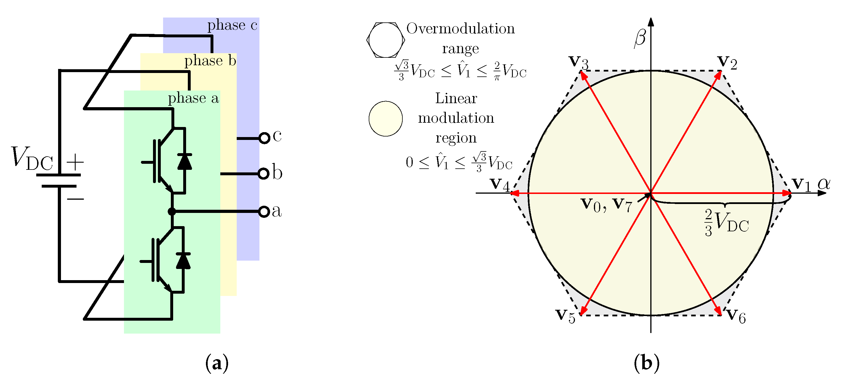
2.4. Voltage Source Inverters

Most commonly, IPMSMs are fed from a VSI, which generates switched voltage waveforms at its output phases with a fundamental voltage component with adjustable frequency, phase and amplitude that match the desired reference voltage generated by the control loop of the drive. Even though the output voltage is a switched signal, the output phase currents are usually close to sinusoidal for electric machines.
The most common and popular solution for three-phase IPMSM drives is the two-level VSI (2L-VSI) (see Figure 7a). It consists of a DC link capacitor, which provides more-or-less-constant DC bus voltage, and two active transistors per phase with their respective antiparallel diodes. 2L-VSI can generate six active voltage vectors in the α β with a magnitude of 2 / 3 V DC , where V DC is the DC-link voltage. Furthermore, two zero voltages can be formed by shortening the output phases either with the upper or the lower transistors.
The VSI can synthesize a fundamental voltage that varies linearly with the reference voltage, which is typically the output signal of the control algorithm, in the so-called linear modulation region. The amplitude of the maximum achievable fundamental voltage in this range is V ^ 1 = 3 / 3 V DC , assuming ideal VSI and neglecting the side effects, like voltage drops and effect of dead time. Most commonly, the carrier-based space vector modulation (SVM) scheme is utilized in this region. The harmonics of the output voltage are located in the high-frequency range around the switching frequency and its integer multiples. This results in a very good harmonic performance if the switching and fundamental frequency ratio is sufficiently large. The amplitude of the fundamental output voltage can be further increased by entering the so-called overmodulation range. The operation of the IPMSM drive in this range requires considerable attention, because the linear relationship between the reference signal and the output fundamental voltage ceases to exist. Furthermore, in this region, the effective switching frequency decreases and the level of harmonic distortion increases gradually due to the lower-frequency harmonics. The SVM method can be also used with appropriate modifications, as was demonstrated in [42]. The upper boundary of the overmodulation range is called the six-step mode, where the inverter outputs the maximum achievable voltage V ^ 1 , max   = 2 / π V DC .
There are so-called discontinuous PWM methods, which are widely utilized, especially in the upper part of the linear and even in the overmodulation region. These techniques have the advantage of reducing the number of switchings, and therefore, the switching losses of the transistors. Paper [43] offers an experimental comparison between different PWM schemes for a 2L-VSI-fed IPMSM drive. So-called programmed modulation techniques can also be utilized to control VSIs. In this case, the overall approach to define the switching times is based on the minimization of a suitable cost function, which typically represents system losses. These optimized pulse patterns can have superior harmonic performance at low switching to fundamental frequency ratios [44]. Typically, the switching instants are calculated offline, and they are stored in look-up tables (LUT) as the function of the modulation index and frequency ratio.
The classic 2L-VSI topology has certain limitations. The output phase current has a low total harmonic distortion (THD), and it is close to the ideal sinusoidal signal if the ratio of applied switching frequency and the synchronous electrical frequency of the machine is a high number. Typically, a high number of pole pairs are preferred for IPMSMs for traction drives to increase the torque capability of the machine. It can result in high synchronous frequency (up to 1 kHz) [16] around the rated speed and in the field weakening region. The thermal limitation of silicon-based transistors restrains the switching frequency, which can result in a low-frequency ratio around or above the rated speed of the machine. It causes a higher distortion in the current and a far more unfavorable harmonic spectrum, both of which increase the losses significantly. One possible solution to overcome this problem and increase the achievable switching frequency is to use advanced semiconductor devices such as silicon carbide (SiC) and gallium nitride (GaN), which have wide-bandgap properties [45,46]. These devices offer a number of benefits over conventional silicon transistors, like a reduction in switching losses, smaller size of heat sinks, the possible elimination of the snubber network and lower dead-time distortions. Paper [45] demonstrates that a higher efficiency can be obtained by using GaN transistors instead of silicon-based IGBT for a PMSM drive fed from 2L-VSI. The conducted common-mode electromagnetic interference emission of motor drives is investigated and quantified for a 2L-VSI-fed motor drive using GaN and SiC transistors in [46]. However, there are disadvantages to utilizing GaN devices, such as the ringing phenomenon caused by the very quick d v / d t and d i / d t . These are investigated thoroughly for IPMSM drive systems in [47]. Paper [48] introduces an analytical loss formulation to predict the efficiency of SiC-based 2L-VSI, which takes into account the influence of the harmonic distortion of the current on the conduction losses, the impact of the output parasitic capacitances and the deadtime on the switching losses.
Another option to overcome the lower harmonic performance of the drive at a low-frequency ratio is to apply multilevel voltage source inverter (ML-VSI) topology. Utilizing ML-VSIs allows for the reduction of harmonic distortion and electromagnetic interference, and switches pressure on the transistors due to lower d v / d t and d i / d t values. The most popular multilevel topologies to supply IPMSM drives are neutral-point clamped (NPC) [49,50], capacitor-clamped or flying capacitor [51] and cascaded H-bridge inverters [52]. Paper [53] reviews the different ML-VSI topologies and examines their benefits and drawbacks from different aspects. Recently, increasing attention has been paid to reduced-switch-count ML-VSI topologies. A detailed survey about the different reduced-switch-count inverters can be found in [54].
In some applications of IPMSMs, such as fans and pumps, where compactness and price competitiveness are more important than precise control, single-phase 2L-VSIs, also called three-phase four-switch (TPFS) inverters, are also applied [55]. A control strategy using a single current sensor is introduced in [56]. Paper [57] proposes a novel TFPS topology with a flying capacitor.
For electric vehicles and propulsion systems, the concept of integrated motor drives, where the motor and its corresponding inverter and control equipment are integrated to take up less space and to eliminate the lengthy cable connection between the machine and the inverter, can be a feasible solution. Paper [58] offers a detailed overview about the technologies related to the integrated motor drive concept.
In the case of open winding IPMSMs, the neutral point of the typically star-connected IPMSM is opened, which allows one to supply the machine from two independently controlled 2L-VSI with common or independent DC source(s) [30]. The operating capabilities and limits of this type of IPMSM drive are summarized in [30]. Paper [59] presents the control strategy along with the proper modulation scheme for an open winding IPMSM used in a premium-class electric vehicle.

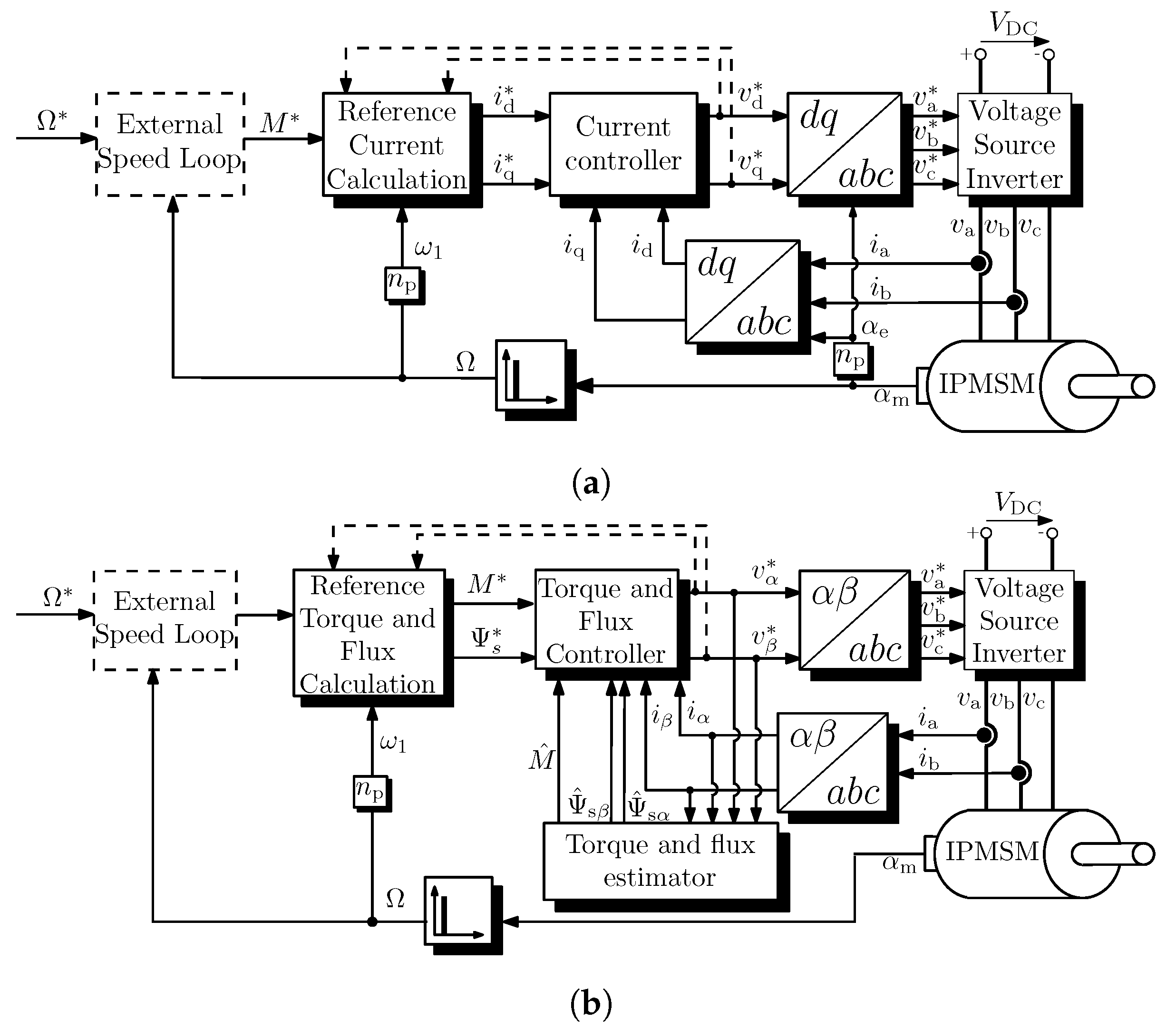
3. Control Techniques of IPMSM Drives

A proper control approach is essential for high-performance electric machines. Generally, two main concepts are utilized for IPMSM drives. In the first approach, the d and q axis stator current components are controlled in the dq frame. A general block diagram can be seen in Figure 8a. For this control structure, the measured phase currents are transformed to the dq frame using the measured electric angle of the machine. The controller generates the reference voltage components v d * and v q * to force the measured i d and i q currents to follow their respective reference signals i d * and i q * . The reference current signals are calculated based on the torque reference M * and the actual electrical frequency ω 1 . During the calculation, the actual operating mode as well as the current and voltage constraints should be taken into account, as was discussed previously. The reference torque can be set externally or it can be produced in a cascade fashion from an outer speed loop to force the actual mechanical angular frequency Ω to track the reference speed Ω * . The reference voltage components v d * and v q * are transformed back to the abc frame to produce the reference signals for the PWM unit of the VSI. Most commonly, the current controllers—as well as the external speed controller—are linear PI type controllers, and this method is referred to as vector control, or most commonly, field-oriented control (FOC). However, as will be presented later, this control approach can be realized by other types of controllers as well.
In the second control approach, the electric torque is controlled directly, along with the stator flux. A general block diagram can be seen in Figure 8b. Typically, this control approach operates in the α β frame. It should be noted that there are also approaches that operate in the dq frame. As the measurement of the electric torque as well as the stator flux is costly and complex, their actual values are estimated using the mathematical model of the IPMSM from the demanded voltage and the measured actual current values. The torque M * and flux Ψ s * reference signals are calculated from an external torque reference M ext * , which can be the output of an external speed loop, as well as the actual electrical frequency ω 1 . During the calculation, the actual operating mode as well as the limitations should be taken into account. Most commonly, hysteresis-type controllers and LUTs are used for the torque and flux controllers, and this method is referred to as direct torque control (DTC). The conventional DTC scheme offers advantages like simple structure, higher robustness against parameter mismatch and fast response. However, there are a few disadvantages of the approach, such as high torque and flux ripples and variable-switching frequency. To overcome these problems, typically, a PWM modulator is applied, and this approach is realized by other types of controllers.
As was mentioned previously, the classic FOC and DTC use PI-type and hysteresis-type controllers, respectively. While both methods have certain advantages, each of them has its own deficiencies and limitations, which can degrade the overall performance of the drive. In the literature, many other types of controllers are utilized to control the current or the flux/torque of IPMSMs to overcome these limitations and improve performance.
In control theory, the controllers can be classified according to several aspects. In this review paper, the most commonly used control approaches used for IPMSM drives are grouped as linear, nonlinear, predictive, robust, intelligent and adaptive (see Figure 9). In the following, each group will be discussed in more detail. It should be noted that the different control methods are also used in combination with one other. For example, model predictive control is used to control the current of the IPMSM machine, while the outer speed loop, which provides the reference current signal, utilizes a linear PI-type controller. Also, hybrid-type controllers can be obtained with the combination of different approaches. For example, sliding mode control is coupled with backstepping control to control the speed and the current of the machine, as presented in [60]. Recently, increasing attention has been paid to dual-stage control strategies, which combine the advantages of different control approaches by commutating between them. For example, model predictive control can have a fast closed-loop dynamic performance, but FOC using a linear PI controller has a good steady-state performance. Depending on the deviation of the state variables from the reference signals, the dual-stage controllers switch between the algorithms [61].

3.1. Linear Controllers

The IPMSM is a complicated nonlinear multivariable system with online variations of system parameters, like inductance saturation or temperature dependency. Nevertheless, even linear control techniques can be applied to obtain high-performance drive systems.

3.1.1. PI Controller

Most commonly, a proportional–integral (PI) controller is considered for current controlled electrical drives (see Figure 8a), as it is the most well-established solution for the current regulation and speed regulation. It offers advantages, like simple structure, fair robustness and high reliability. However, for proper operation, the controller gains should be tuned with special care. As can be seen in (6), there is cross-coupling between the d an q axis equations. Typically, during the design of the linear PI controller, these terms are not taken into account, and a linear, one-energy storage element model is assumed for the design of the current loop. These cross-coupling components are decoupled by adding their estimated value to the output of the controllers.
Although in practice, the controller parameters are often determined empirically by trial and error, many techniques for the calculation of gains have been developed in the literature. Paper [62] presents a classic, textbook design methodology based on magnitude and symmetrical optimum to design the controller gains of the current as well as the outer speed loop by using continuous transfer functions. The focus of the paper was put on the achievable control bandwidth, dependant on chosen design parameters such as sampling rate, sampling strategy, and filter constants. Paper [63] introduces a simple rule of thumb to achieve nearly the minimum settling time in combination with negligible overshoot, even when the effect of computational delay is taken into account. An overview of common tuning rules is introduced and some general recommendations for the calculation of the gains are proposed in [64]. An automatic control loop tuning method for IPMSMs is presented in [65]. This method can estimate the electrical and mechanical parameters of the drive to calculate the controller gains.
In the case of an IPMSM with a high-rated frequency, the low value of the controller sampling frequency and the fundamental frequency can deteriorate the performance of the drive, or even can cause stability issues. Paper [66] provides design guidance for the digital controller to overcome the issue caused by the low-frequency ratio. A similar issue appears in high-power drives, where the limited switching (sampling) frequency causes a low-frequency ratio, even at standard fundamental frequencies. The method using an active damping function along with a current predictor proposed in [67] also addresses the problem caused by the low-frequency ratio, and can improve the disturbance rejection capability. In the case of active damping, a virtual resistance feedback is used to increase the stiffness of the current loop. It provides a similar effect like increasing the physical resistance of the machine. The time delay introduced into the feedback path creates difficulties for the current controller using active damping. Paper [68] suggests a novel structure along with a gain-setting procedure to overcome the issue caused by the time delay. Papers [67,68] use complex vector current controllers. This control concept, introduced in [69], simplifies the current loop and offers a better dynamic decoupling and parameter robustness compared to the traditional structure, where the d and q axis current are controlled separately.
As in most cases, the design methods of the controller gain are based on the machine parameters; the control performance of linear PI-type controllers can deteriorate in the presence of parameter mismatch. Parameter mismatch can occur due to inverter nonlinearities, temperature change and saturation. Therefore, it is necessary to design high-precision controllers with robustness to disturbances in the drive systems. Various methods have been proposed recently to overcome problems caused by the parameter uncertainties, like online parameter estimation [70,71,72,73,74], using the disturbance observer [75,76] or the previously mentioned active damping technique [67,68].
An overview of offline and online parameter identification methods for PMSM drives is given in [70]. Paper [71] proposes a method for the torque control of an IPMSM, which injects a sinusoidal disturbance current in the d axis. From the response, the actual value of R s , L d , L q and Ψ PM can be estimated effectively using recursive least-squares algorithm. A parameter estimation method based on affine projection algorithms combined with adaptive PI controllers is introduced in [72]. In addition to the machine parameters, the method estimates the actual value of the loading torque as well. Paper [73] also presents an affine projection-based parameter estimation method with a faster convergence rate. Furthermore, the technique does not need any prior exact value of machine parameters. An online parameter estimation technique based on current injection and recursive least-squares algorithm is introduced in [74]. The paper also replaces the conventional PI controller to improve the performance and the bandwidth of the current loop to a neural-network-based PID control with a real-time learning algorithm.
A survey about techniques to estimate and attenuate different disturbance or uncertainty in PMSM drives is given in [75]. A high-order disturbance observer combined with a PI controller to regulate the speed of PMSMs is presented in [76]. The method effectively estimates the load torque as well as the disturbances caused by cogging torque and electromagnetic noise.
PI controllers in the current loop are designed to control the fundamental current vector, or in other words, the average value of the d and q axis current components. Due to the switching nature of the VSI, the stator currents—both in the abc, α β and dq coordinate systems—contain high-frequency ripples. The time instant of the current sampling plays a decisive role for the exact acquisition of the fundamental waveform. Therefore, it has an important role on the performance of the control loops. Typically, carrier-based PWM techniques, like SVM, are utilized for current control with PI-type controllers. The phase currents are sampled at the negative, positive or both peaks of the carrier signal. In an ideal case, it results in ripple-free current signals for the controllers. This concept works well in the linear modulation range (see Figure 7b). It should be noted, even in this region, that switching noise and parasitic oscillations can introduce sampling errors. Paper [68] proposes a method where the effect of the ripples in the sampled current are avoided by oversampling. If the drive enters the overmodulation region (see Figure 7b), additional current harmonics appears in the sampled signal, which deteriorates the performance or can even cause stability problems. One possible solution to overcome the problem is to limit the operation of the VSI in the linear modulation range, but it results in a suboptimal utilization of the inverter [77,78]. Another approach is to use the current controller only in the linear modulation range and apply the voltage angle control method to utilize the overmodulation range [79]. The clear disadvantage of this method is the limited dynamic performance. Another possibility to eliminate the harmonics in the sampled current is to use low-pass filtering in the feedback path [80]. While this method solves the problem caused by harmonic currents, it also limits the bandwidth of the current controller. Another approach is to estimate the harmonic current by using a mathematical model [81]. Then, the estimated harmonic current can be subtracted from the measured signal to obtain the ripple-free fundamental current components. This approach works properly in a steady state, but causes problems during transience due to the inherent dynamics of the estimator algorithm. Paper [82] proposes a simple structure taking into account the nonlinearity in the overmodulation region for IPMSM drives. It directly uses the measured currents; therefore, there is no need for either filtering or harmonic current estimation. The scheme proposed in [79] can realize the operation of the IPMSM in the overmodulation region, even for a six-step operation.

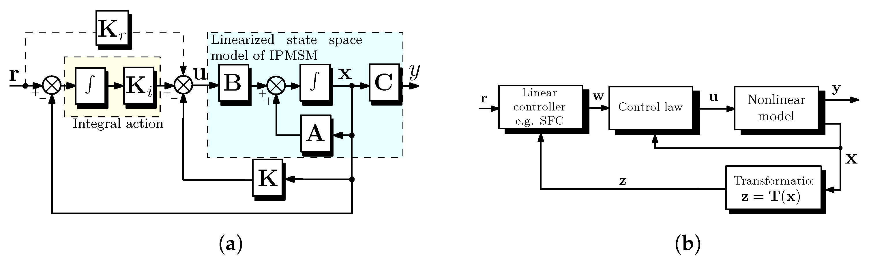
3.1.2. State Feedback

State feedback control (SFC) uses the state vector, which contains the state variables of the plant, to compute the control action to obtain a specified dynamics. This control approach is a widely used technique for the controlling of switching-mode power electronics converters, like DC/DC converters. Although this is a less widely used method for controlling electrical drives, especially IPMSMs, it can be a feasible alternative approach, as demonstrated in several papers [83,84,85,86,87,88,89,90]. As there is only one controller in this structure for all state variables, the typical cascaded structure—inner current loop and outer speed loop (see Figure 8)—can be omitted, and the drawbacks of the cascaded structure can be overcome. The main drawbacks of the SFC technique are the more complex control design procedure and the lack of constraints in the control algorithm. To mitigate the latter deficiency, a model predictive approach is introduced in [83], which can limit selected state variables.
During SFC control of IPMSMs, the state-space representation of the machine is required. Typically, the i d and i q current components and the Ω = P ω 1 mechanical speed are selected as state variables, and they form the state vector x , while the input vector u contains the v d and v q voltage components [91]. The state space model can be obtained using the Equations (6), (9) and (10). These equations describe a nonlinear system. Therefore, the nonlinear IPMSM model should be linearized for a given operating point, as given in [84]. The SFC provides optimal control only in the close vicinity of the working point. To overcome this problem, papers [85,87] linearize the nonlinear mathematical model of IPMSM by means of the quadratic linearization method, which is able to linearize systems with various operating points without introducing any singularity points.
It should be noted that the linearized IPMSM model is a type 0 system, so the SFC in a closed-loop application does not eliminate the steady-state error. For this reason, an integral term should be added, which entails the introduction of new state variable(s) in the state vector and results in an augmented state space model [86,87]. A general block diagram of SFC for IPMSM with integral action can be seen in Figure 10a, with the notations widely used in the literature. The dashed line indicates a reference feedforward compensation, which may be necessary, as demonstrated in [88] for the current control of IPMSM using SFC.
As was mentioned, in the case of SFC, the state variables of the system are fed back through a feedback gain matrix, most commonly denoted by K (see Figure 10a). Several methods exist to calculate K . For example, by knowing the location of the desired poles of the closed-loop system, the pole placement technique can be used [88]. The main drawback of the pole placement technique is that the proper location of poles usually requires expert knowledge and seems to be a challenging task for an IPMSM machine. The pole placement technique for the torque control of IPMSM is utilized in [89]. The paper applies a novel coordinate system to control the amplitude and the phase of the voltage with an SFC combined with linear PI controller. A widely used technique for IPMSM machines to calculate K is based on the linear quadratic regulator (LQR) approach. The LQR is an optimal control method that aims to minimize the cost of a quadratic function. The designer can weigh which states and which inputs are more important in the control action to seek for appropriate transient and steady-state performances. For the LQR approach, the selection of Q and R matrices is necessary and plays an important role. The Q matrix contains weights that penalize the deviations of the state variables from the desired state, while R contains the weights that penalize the control effort. The calculation of K from a given Q and R matrices using the solution of the so-called algebraic Riccati equation is described in [84,87]. Paper [90] proposes and compares two nature-inspired optimization algorithms to obtain Q and R matrices. For the same goal, particle swarm and gray wolf optimization techniques are used in [85,86], respectively. Paper [92] proposes an augmented state space model of a PMSM containing the information of periodic disturbances. As the new state variables cannot be measured directly, a disturbance observer is utilized. An LQR-based control is proposed, which can achieve the successful suppression of the periodic disturbances and can improve the performance of the drive.
According to the findings of the authors, only a few articles, like [87,89] demonstrate the operation of the proposed SFC-based approach in the overmodulation range. This is because in the overmodulation region, as it was discussed previously, the feedback signals contain low-order harmonics, and the feedback gains should be most likely drastically modified, which can deteriorate the control performance. This problem can be solved by using some other control strategy in this region or limit the operation to the linear modulation range.

3.2. Nonlinear Controllers

As IPMSM is a nonlinear system, a straightforward choice would be to apply nonlinear controllers to control the speed and/or the current of the machine.

3.2.1. Feedback Linearization

Feedback linearization (FBL) is a common nonlinear control approach, with the concept to transform a nonlinear system into a fully or partially decoupled controllable linear one by means of state feedback and nonlinear transformation. This allows for the use of a linear controller, very commonly SFC, to achieve the control objective [93]. The main objective using the FBL technique is to find a proper nonlinear transformation z = T ( x ) , which transforms the x state vector of the nonlinear system into a z coordinates of a linear system. Most commonly, this transformation is performed by using the so-called Lie differential operation. Such linearization has higher accuracy, since the linear approximation is not employed, which means that no higher-order nonlinear terms are ignored. So, the method preserves all state features of the system, and the derived mathematical model is linear and complete. This is the main difference between feedback linearization and traditional linearization methods. For FBL, a control law should be also formulated, which maps the control signal w of the linear controller to the control signal u of the nonlinear system. A general block diagram of the FBL control can be seen in Figure 10b.
Paper [94] proposes an FBL control for IPMSMs. The paper introduces a generalized linearization model of an IPMSM, and the Hamiltonian of optimal control theory is applied to achieve an optimal control for a wide speed and torque range. A FBL control approach is utilized for the inner current loop for an IPMSM drive with capability to work even in the field-weakening region in [95]. In the paper, the Lie differential operation is performed on the state vector and SFC control is used. The feedback gain matrix is calculated using the pole placement technique. An FBL controller is suggested in [96] for the DTC of an IPMSM. The proposed method can take into account the maximum voltage of the inverter as a constraint. Furthermore, the Hamiltonian of optimal control theory is combined with an improved firefly algorithm for the calculation of the controller parameters. Papers [97,98] also present the design methodology for the DTC of IPMSMs using FBL. It is verified in both papers that a faster torque response, smaller torque ripple and lower stator flux ripple can be obtained compared to the conventional DTC approach using an SVM modulator, even at lower operational speed, where the classic DTC approach is affected by unwanted field-weakening phenomena.

3.2.2. Sliding Mode Control

Sliding mode control (SMC) is an efficient approach for controlling complex nonlinear systems having uncertain dynamics and disturbances. SMC has two parts: a reaching/control law and the sliding surface. The reaching law forces the system states to reach the sliding surface.
SMC methods can be classified into two groups, depending on whether they use a linear or nonlinear sliding surface [99]. The linear sliding mode surface, where the surface is the linear function of the system states, is commonly used as it is simple and convenient, and the design of its parameters is relatively easy. However, techniques using linear surfaces can cause nonuniform performance and large chattering. Nonlinear-sliding-surface-based methods, like terminal [100] or integral SMC [101], have advantages like better handling of model uncertainties and disturbances and the characteristics of gradual convergence. However, they can also exhibit chattering phenomenon. Terminal SMC can improve the speed of convergence, but the tracking error converges slowly when it is distant from the equilibrium compared to linear SMC. Furthermore, it has a singularity problem near the equilibrium point. A nonsingular terminal SMC is introduced in [102], while a so-called fast terminal SMC method, which solves the issue of the slower convergence rate far from the equilibrium point, is proposed in [103]. Integral SMC is another widely used nonlinear technique, where an integrator is used to eliminate the steady-state error [104]. An adaptive integral SMC with fractional sliding surface is used in [101]. While the suggested controller provides a robust performance, the system no longer has reduced-order characteristics on the sliding mode surface, which makes the calculation complicated. To combine their respective advantages, fast integral terminal SMC techniques are proposed for the speed control of IPMSM in [105,106]. Both methods utilize a disturbance observer as well.
The major disadvantage of SMC techniques is chattering, which makes it difficult to apply SMC in practice for drive systems. The main source of the chattering is that although the reaching law forces the system states to reach the sliding surface, it is hard to keep them on the surface with zero error. The states of the system constantly pass both sides of the sliding surface, resulting in unwanted chattering. Therefore, the key for proper operation of SMC techniques is the reduction of this chattering phenomenon [107]. The reaching law contains the switching function, which results in chattering. If the gain of the switching function is set to a larger value, then the SMC is more robust and can compensate disturbances, but it can also lead to a high-frequency chattering. The smaller value of the switching gain reduces the system chattering, but also the level of robustness against disturbances, and can increase the reaching time. Therefore, gain selection plays an important role. Paper [108] proposes a method that tunes the switching gain online using an adaptive method. The chattering phenomenon can also be alleviated by applying more advanced reaching laws. A novel exponential reaching law is proposed in [109] to improve the robustness against machine parameter variations. A modified and simple-to-implement exponential reaching law is introduced in [110] for IPMSMs considering the effect of magnetic saturation. A reaching law, which includes the system variable and the power term of sliding surface function, is presented in [111]. A novel adaptive reaching law with terminal SMC is proposed in [107], which provides a better performance than SMC using the conventional exponential reaching law.
The effect of the problem caused by the chattering can be also minimized by using a disturbance-observer-based feedforward compensation technique. Its advantage is that the switching gain can be significantly reduced while maintaining the ability to resist unknown disturbances [104,112]. A general overview about disturbance-observer-based control techniques can be found in [113]. A super-twisting SMC control with a support vector regression disturbance observer is presented in [99]. An improved exponential reaching law, which adaptively adjusts the approach-speed-based SMC combined with a disturbance observer for the load torque is introduced in [102]. Paper [100] proposes a nonlinear disturbance observer to the terminal SMC to estimate the disturbance, instead of a conventional load torque observer.
It should be noted that the SMC approach is predominantly used only for the speed control of IPMSMs, like [99,105,106,107,108,111,112]. Typically, SMC provides the reference signals for the inner current loops, which use conventional linear PI controllers. There are also papers where not only the speed but also the d and q axis currents are controlled by SMC, like [60,100,101,114,115]. Paper [114] uses separate SMC for the speed, torque and flux controller for a surface-mounted PMSM. The approach used in the paper can also be used for the control of an IPMSM. A high-order SMC coupled with backstepping control (see next section) is introduced in [60] for the speed and current control of IPMSMs.

3.2.3. Backstepping

One direct way to design a controller for nonlinear systems like IPMSM is to apply the Lyapunov stability theory [116]. However, finding a suitable control Lyapunov function is a challenging problem for nonlinear control systems. The backstepping control, which was developed in the early 90s, is a recursive design procedure. A virtual control variable is obtained in each step to make the initial high-order system uncomplicated. Consequently, the final control signals can be acquired gradually by means of appropriate Lyapunov functions [117]. The method guarantees global asymptotic stability of strict feedback systems and can effectively control uncertain nonlinear systems. It is a practical tool to overcome the deficiencies of the feedback linearization approach.
Recently, the backstepping control method has attracted much attention for electrical drives because it is easy to combine with adaptive parameter estimation techniques to weaken the influence of system uncertainties [118]. Furthermore, in the case of the current control of IPMSM, it can achieve the complete decoupling between d and q axes. An integral action to remove constant steady-state error, can be included in backstepping control, either by parameter adaptation or augmented by state variables by a new integrated state variable.
The major limitation of backstepping control is that there is no standard approach to tune the parameters. According to the Lyapunov function, only the lower limit of each parameter can be obtained, but the exact value of parameters cannot be determined. During the control design, the parameter selection can only be realized by experience and trial and error. Furthermore, typically, the parameters of a backstepping controller are selected to be a fixed constant value, which limits the dynamic performance. To overcome this problem, some intelligent or adaptive logic is applied, which adjusts the parameters online.
Direct torque control of IPMSM using backstepping control is presented in [119]. As the exact value of the machine parameters has an impact on the performance of the control, a recursive least-squares method identification is also applied. An integral backstepping control approach is compared with a PI-type control-based current control of IPMSMs by an experimental test in [120]. The paper demonstrates the feasibility of the backstepping control approach. Paper [118] proposes an adaptive, integral backstepping control for IPMSMs, where the integral of the d and q axis current errors are introduced in the control law. The application of adaptive weight particle swarm optimization is presented to optimize the parameters of the controller. An adaptive backstepping speed controller design method is introduced for surface-mounted PMSMs in [121] in the presence of parametric uncertainties. The method uses only the lower and upper bounds of the machine parameters, and the optimal control gain is determined by solving an optimization problem under bilinear matrix inequality constraints. An adaptive backstepping controller with a novel load torque update law is presented in [122].
The backstepping algorithm can be used not only for control, but also for estimation purposes. A discrete time SMC to control the current of an IPMSM is introduced in [115], where the applied disturbance observer is based on the backstepping approach.

3.2.4. Gain Scheduling

The gain scheduling technique is a widely utilized method for controlling nonlinear systems with varying operating conditions. The approach is utilized, when the calculated controller gains do not provide the desired performance and stability for the entire operating region of the system. Gain scheduling is not a stand-alone control method. It is typically used together with other control strategies—typically linear PI controllers or SFC—to calculate or modify the controller gains during operation.
The controller gains for LQR control are calculated using gain scheduling in [84]. Paper [123] utilizes the gain scheduling concept for the speed control of IPMSMs using SFC. An approximated linear model is developed for the machine, and the controller gains are calculated for various operating points. Then, a scheduling scheme is obtained to form a nonlinear controller that can cover the drive system in the entire operating range. A gain scheduling approach for the determination of the controller gains of the PI controllers is introduced in [124].

3.2.5. Hysteresis Control

The operation of hysteresis control (HC) is as follows: every time the error between the reference and controlled state variable crosses either the positive or negative hysteresis band’s boundary, the controller creates a significant change in the output signal, which forces the error back towards the hysteresis band. The main advantages of the HC technique are related to its simple implementation, quick dynamic response and high level of robustness [125]. The method can be easily adopted to control the current, the torque or the flux of an electric machine.
As it was mentioned previously, the conventional DTC scheme originally utilizes HC and a Look-up table (LUT) to generate the switching signals. However, this approach has the significant disadvantages of high torque and flux ripples and varying switching frequency [126]. These problems can be overcome either by using other control approaches or by using a more sophisticated HC technique. Paper [49] proposes a two-level HC for the flux control and a four-level HC for a 3L NPC VSI. The proposed algorithm utilizes the average value of the torque error without requiring speed information. As was demonstrated, the method attains the advantage of conventional DTC along with a reduction in torque and flux ripple.
HC techniques, with a few exceptions, are used less often these days for the control of electrical drives. However, they can be useful approaches, for example, when the drive utilizes dual-stage controllers. Switching between controllers is a challenging task that causes undesired bumps and oscillations [61]. An HC approach is utilized in [127] to commutate between model predictive control and a linear PI controller to control a flying capacitor VSI. An average-current ripple-based HC scheme is proposed, along with an artificial neural network-based method, in [61] for PMSM drive systems. The proposed schemes can commutate effectively between model predictive control and FOC using PI controllers to obtain a high-performance drive system. Hysteresis-based solutions can be applied for the generation of the reference signal as well. A novel hysteresis reference generator for the speed signal is introduced in [87]. The main idea is to apply a reference speed with an adjustable average value rather than a step reference with constant magnitude.

3.3. Predictive Control

Predictive control (PC) is a control algorithm based on a predictive model of the system. The model is used to predict the future behavior of the system, based on historical and actual information, as well as possible future control inputs. This information is used by the controller to obtain an optimal actuation according to an optimization criterion. Predictive controllers have undergone several developments over the years, and are classified into four main categories in power electronics [128]: hysteresis-based PCs, trajectory-based PCs, deadbeat control and model PCs (MPC). For hysteresis-based PCs, the controlled variable is kept within boundaries of a hysteresis area. In the case of trajectory-based PCs, the variables are forced to follow a predefined trajectory. In deadbeat control, the optimal control action makes the error equal to zero in the next sampling period. For MPCs, a more flexible criterion, expressed by cost function(s), is used to determine the optimal control action.
The combination of the hysteresis-based control and the trajectory-based control has become an independent family in drive applications, known as the DTC [129]. Recently, MPCs have become an attractive strategy for controlling IPMSM drives, which must meet high-quality requirements. Therefore, in this paper, this concept is discussed in more detail, but the basic concept of predictive deadbeat control will be also introduced.

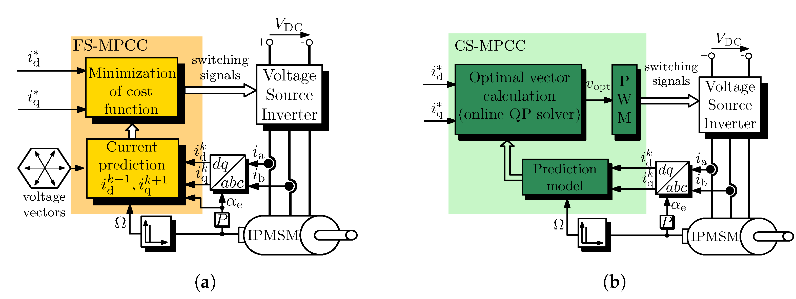
3.3.1. Model Predictive Control

MPC methods were first used more than 40 years ago, in the late 1970s. While they offer many advantages compared to linear PI controllers, for a long time, the high computing power needed limited their use to chemical and process-engineering systems with large time constants. At the same time, the spectacular development of digital devices and the significant reduction in their prices have made it possible to apply MPC techniques for systems with small time constants, such as electrical drives. MPC techniques offer advantages like the possibility to use foreknowledge about the drive system, the inclusion of nonlinearities and constraints (voltage and current) and multivariable control using a single control loop. However, as mentioned, they typically require higher processing capabilities.
MPC methods for electrical drives generally consist of four main steps: measurement—and if necessary, estimation—of the state variables; prediction for the selected variables until a predefined horizontal length denoted by N; evaluation of the cost function(s) for the predicted states; and the selection of the optimal control action [130]. Papers [129,131] give a detailed comprehensive overview about the MPC methods for electrical drives. Paper [129] introduces the main concept and different strategies, while a detailed benchmark of MPC methods with other standard methods, like PI controller-based FOC, is presented in [131].
MPC techniques can be classified according to several aspects. In this paper, the techniques are divided into two main categories: finite set MPC (FS-MPC) and continuous set MPC (CS-MPC). Another classification is whether the current (Figure 8a) or the torque (Figure 8b) of the machine is controlled by a properly selected cost function. The first one is called a model predictive current control (MPCC), while the latter one is referred as a Model Predictive Torque Control (MPTC). It should be noted that in addition to the control of the torque and the current of the machine, MPCs are also considered to implement the outer speed loop of the drive as well. They can provide robustness against parameter modification and operation of the machine in the field-weakening region. Paper [132] proposes a cascade control scheme for an IPMSM drive, where both the speed and the current of the machine are controlled by a separate MPC algorithm. The performance and robustness of the solution are compared to the classic linear controller-based conventional FOC scheme.
In the case of FS-MPCschemes, the finite set of possible switching states of the VSI, which feeds the IPMSM, is taken into account. Therefore, these methods predict the state variables and evaluate the cost function(s) only for the applicable voltage vectors (control actions) of the VSI. Then, the voltage vector, which minimizes the cost function(s), is selected as the optimal control action. For example, in the case of a 2L-VSI and a 3L-VSI, there are 7 and 19 possible voltage vectors, respectively. After the selection of the optimal voltage vector, the controller directly outputs the switching signals belonging to the selected voltage vector. The block diagram of an FS-MPCC scheme using 2L-VSI can be seen in Figure 11a. The main advantage of FS-MPC approaches are the intuitive design procedure, simple inclusion of constraints and the straightforward way of implementation [133]. In addition to this, the horizontal length typically is set to N = 1 , which further simplifies the calculations. However, to obtain a proper performance, some design guidelines, summarized in [134], should be followed. The major disadvantage of FS-MPC techniques is that they need a high sampling frequency, while the typical equivalent switching frequency is around 20–25% of the sampling frequency [133]. Another drawback of conventional FS-MPC techniques is that the torque ripple can be significant, as only a single voltage vector is applied in each sampling period. Furthermore, the computational burden for prediction and cost function evaluation rises significantly as the total number of allowable voltage vectors increases.
The steady-state performance, like limited harmonic performance and higher torque ripples, can be improved by using an implicit modulator stage. In this case, the switching instants and duty ratios of the voltage vectors applied during one sampling period are determined. These techniques are called multiple-vector-based MPC schemes. The most common method is to apply one active and one zero-voltage vector and adjust their duty ratios. An MPC with a duty cycle optimization procedure for a 2L-VSI-fed IPMSM drive is introduced in [135]. Furthermore, to reduce the computational time, a LUT is proposed that allows one to use four voltage vectors instead of seven for the prediction and cost function evaluation. Also, an LUT based FS-MPC method is presented in [50] for a 3L NPC VSI to reduce the number of admissible voltage vectors effectively. A so-called generalized multiple-vector-based scheme, which calculates the duty ratios of two voltage vectors applied during one sampling period, is introduced in [136]. The method, instead of using an LUT, reduces the computational burden by utilizing a reference voltage vector obtained from a deadbeat control scheme. Paper [137] introduces an MPC technique that determines the optimal duty ratios for three voltage vectors.
In addition to controlling the duty ratio, another viable strategy is to create virtual voltage vectors. Paper [138] presents a two-stage FS-MPC for 3L-VSI using 48 virtual voltage vectors and discrete space vector modulation. An MPC scheme using 20 applicable voltage vectors is introduced in [139], where the sampling period is subdivided into two equal time intervals. The output voltage vector is innovatively determined through two hysteresis controllers, which reduces the computational time, as there is no need to evaluate all the voltage vectors. A simplified virtual vector-based MPC technique is proposed in [140]. An improved MPTC scheme for IPMSMs using discrete space vector modulation is presented in [141]. The modified cost function includes the excitation torque and reluctance torque components, which eliminates the weighting factor (see later) and also reduces the torque ripples.
CS-MPC approaches, often referred as infinite set MPCs, do not take into account the switching mode behavior of power electronic converters. The optimal control action is determined by calculating the minimum of a continuous cost function. These methods typically apply a PWM modulator stage, and the calculated optimal control action is provided by the modulator. Therefore, these methods are often referred to as indirect schemes as well. The block diagram of an CS-MPCC scheme can be seen in Figure 11b. The use of a modulator stage results in constant switching frequency and—depending on the applied PWM technique and the switching to a fundamental frequency ratio—a very good harmonic performance and lower torque ripple compared to FS-MPC approaches. However, it should be noted that the output voltage of the VSI is limited (see Figure 7b). This constraint should be taken into account during the calculation of the optimal control action. The constrained optimization problem, which needs to be solved in real time, increases the computational burden, which in general also increases with the horizontal length N. For electrical drives, an excellent performance can often be achieved with relatively small horizons, even with N = 1 [134].
For CS-MPC methods, a quadratic programming (QP) problem, which takes into account the constraints of the system, should be solved online. Gradient methods [31,142] and active-set methods [143] are the two most commonly used QP solver techniques for electrical drives. It should be noted that most of the QP solvers apply an iterative numerical method, which can drastically increase the computational load [144]. Paper [31] proposes an iteration scheme with a fixed number of steps for IPMSM drives using a nonlinear dq model, which takes into account the saturation and parasitic effects. An MPC scheme for PMSMs using the active-set method and implemented on low-performance hardware is presented in [143]. A computationally efficient method with a maximum number of arithmetic operations is proposed in [144] for VSI applications, like IPMSM drives, with hexagonal voltage constraints.
A novel MPC scheme with integral control action and a disturbance observer for an IPMSM is proposed in [145]. A CS-MPCC method suitable for real-time applications is proposed in [146]. Furthermore, the approach uses an incremental model that eliminates the permanent-magnet flux linkage, providing strong robustness. A novel method, which transforms FS-MPC to CS-MPC, is presented in [147]. The method evaluates the cost function for seven voltage vectors, like FS-MPC schemes. Based on the cost function results of the seven voltage vectors, a quadratic regression model is developed that maps the cost function to the whole modulation region. After solving a noniterative constrained optimization problem, the optimal voltage vector can be applied similarly to CS-MPC schemes.
As model-based MPC methods apply the mathematical model of the machine, their performance is sensitive to parameter disturbances, like varying inductances. A FS-MPCC method suited for IPMSM machines with cross and saturation effects is presented in [148]. The suggested control can be realized without the knowledge of exact motor parameters except the permanent-magnet flux linkage as a datasheet parameter. The effectiveness of the Adaline linear neural network for online parameter estimation combined with the FS-MPCC method is demonstrated in [149]. An inductance disturbance observer is introduced in [150] to improve the robustness of the current prediction against machine parameter mismatches for an FS-MPCC scheme. For similar reasons, an extended sliding mode observer with a multidimensional sliding mode surface is designed in [151]. While observed-based solutions provide a more robust performance than conventional MPC schemes, observer parameters need to be properly tuned to obtain an optimal performance [152], which makes their practical implementation challenging. Another approach to enhance the robustness of MPC is to avoid the use of machine parameters. These techniques are called model-free MPC methods [152]. One of the methods is to use an ultralocal model [153,154] or to apply an autoregressive with exogenous input model [155]. In both cases, the original machine model is replaced by a general linear input–output model. Another form of model-free MPC method is to use LUTs to store information of current variation induced by the inverter voltage vectors [156]. An autoregressive moving average structure is proposed in [157] for a model-free MPCC approach for PMSM drives. The paper demonstrates that the control technique has better performance, such as better harmonic performance and robustness, than conventional ultralocal model-based solutions. A model-free FS-MPC scheme for 3L NPC-type VSI-fed PMSM drives is introduced in [158], where the prediction error is drastically reduced compared to the LUT-based solution of low-frequency ratios. Furthermore, the neutral point of the NPC-type inverter is effectively balanced without information on the value of DC link capacitor. A novel paradigm, known as a data-driven MPC, is introduced in [159], where a reduced model is constructed based on the singular value decomposition of raw data. The paper contains design guidelines as well for the usage and implementation of this concept. The same authors investigate the feasibility of data-driven predictive control in [160]. A systematic concept is introduced in the paper to reduce the complexity of data-driven approaches and overcome the limitation caused by the constraints in real-time implementation.
The proper operation of the machine in the overmodulation region is a key concern for MPC techniques as well. Typically, the conventional FS-MPC approaches using a single vector cannot utilize the full modulation region, including the linear as well as the overmodulation parts. Using multiple-vector-based MPC schemes or digital space vector modulation can allow for operation, even in the overmodulation region. Paper [161] proposes a scheme for multiple-vector-based MPCs with the capability to operate also in the overmodulation region. The computational burden of the method is independent on the number of virtual voltage vectors, whose value can be set arbitrary to obtain a good harmonic performance. An FS-MPCC strategy with overmodulation capacity is introduced in [162]. The duration of voltage vectors in the overmodulation region can be obtained by using a uniform penalty function. In the case of CS-MPC methods, the controller outputs a voltage vector bounded by either the hexagon (linear and overmodulation range) or circle voltage constraint (only linear modulation range) (see Figure 7b). Most of the papers, like [31,163], presenting CS-MPC approaches, use a circle voltage constraint by limiting the amplitude of the output voltage vector (length of voltage vector either in the α β or dq coordinate system) to 3 / 3 V DC . Therefore, only the linear modulation range is utilized. A CS-MPCC method for an IPMSM with the capability to work even in the overmodulation region, including the six-step operation mode, is introduced in [78]. The methods presented in [144,147] also have the capability to work in the overmodulation region.
As mentioned previously, good control performance can be obtained by selecting the prediction horizon to be N = 1 . However, in special applications, like high-power electrical drives with limited switching frequency or high-order systems, where an LC filter is placed between the VSI and the machine, the increase in the prediction horizon can improve the harmonic distortion [129]. These so-called multistep FS-MPC schemes have recently gained increasing attention [164,165].
As was mentioned in the theoretical background, optimized pulse patterns can have superior harmonic performance for drives operating at low switching to fundamental frequency ratios. These methods provide optimal harmonic performance in a steady state, but during transients, improper operation may occur. Model predictive pulse pattern control (MP3C) methods can overcome the problems caused by transients by manipulating the switching instants of the precalculated optimized pulse pattern in real time [166]. Paper [166] presents a generalized MP3C scheme based on a small-signal linearization around the nominal switching instants.
The MPC method chooses the optimal control action based on one or more cost functions. Cost functions can include the error of the given action from the reference signal, the constraints of the system and other chosen penalties. The final cost of an action is obtained by weighting these features against each other. An optimal cost function would provide a compromise for each of these features. There exist a number of solutions to design weighting factors adequately. In most cases, the weighting factors are fixed numbers based on the features. An overview and a comparison of different weighting factor calculation methods are given in [167]. Paper [168] presents an analytical tuning algorithm for FS-MPTC scheme, that adjusts the value of the weighting factor where the cost function only includes the reference errors of the torque and the flux. Cost functions with more than two features, or in other words multi-objective cost functions, pose a more complex design issue. The bees algorithm, which is a population-based search algorithm, is used to obtain the optimal value of weighting factors in [169]. An artificial neural network for the selection of weighting factors for an MPTC scheme is introduced in [170]. Using such an advanced techniques for the weighting factor design is a promising technique, but it goes in the opposite direction of the conceptual simplicity of predictive control [129]. Paper [171] proposes a general dynamic weighting factor calculation scheme. There are also attempts to completely eliminate weighting factors. Paper [172] proposes an intuitive decision-making logic for the sequence of cost function execution in an online self-adjustable manner for IPMSM drives. A similar decision-making concept is utilized in [173]. In the paper, the cost function is split, and a sorting algorithm is utilized for each control objective to determine the optimal control action without a weighting factor. A so-called sequential MPC is introduced in [174], where as a first step, the two voltage vectors with the smallest value for the cost feature expressing the torque error are selected. In the second step, the other cost feature expressing the current of flux error is calculated only for these two voltage vectors to select the optimal one.

3.3.2. Predictive Deadbeat Control

As was mentioned previously, one form of predictive control is so-called predictive deadbeat control. Typically, deadbeat control, for example, in the case of state-feedback control, utilizes the pole placement technique, and the poles of the discrete system are placed at the origin of the z-plane. For a controllable system, it eliminates the system dynamics, achieving an almost-perfect response. Theoretically, in deadbeat control, the error between the reference signals and the state variables are forced to zero for unbounded control signals in k sampling periods, where k is the order of the controlled system. If the sampling time is very short, the response time will be very short. However, the control signal can have very large value, and most likely, it will be bounded by constraints of the system, like maximum output voltage or current, which increases the settling time. Therefore, in deadbeat control, special care should be given to the selection of the sampling time.
For predictive deadbeat control (PDBC), the mathematical model of the system is used to calculate the control signal—in the case of IPMSMs, the output voltage of the inverter—to minimize the error between the given state variables and their respective reference signals. Similarly to CS-MPC methods, PDBC utilizes a PWM modulator to generate the output voltage. PDBC techniques can be classified as predictive deadbeat current control (PDBCC) [175] and predictive deadbeat torque (and flux) control (PDBTC) [176] (similar to Figure 8).
Paper [177] proposes a PDBCC scheme in the dq coordinate system for IPMSMs. The paper compares the performance with the standard FOC approach using linear PI controllers. A PDBCC method, with the capability to remove abundant harmonics in the stator current, which is typical for IPMSM drives, is introduced in [178]. In order to achieve the suppression of current harmonics, a current harmonic extraction method and current harmonic controller are proposed in the paper. Also, a PDBCC method is introduced in [175], which can be used for IPMSM drives with very highly rated electrical frequencies and with limited sampling to fundamental frequency ratios. A FW control method based on PDBCC for an IPMSM is introduced in [179]. A PDBTC approach is introduced for IPMSMs in [176]. As conventionally the reference torque is produced by an outer PI-type speed control loop, which degrades the dynamics and the precision of the drive under external disturbances, an SMC strategy-based solution is suggested in the paper. A multiple-vector-based FS-MPC control for IPMSMs is proposed in [180]. The method uses a modified deadbeat prediction model with integral action, which improves the steady-state performance, robustness and disturbance rejection compared to conventional FS-MPC schemes. The stability analysis, based on eigenvalue migration, of the PDBTC scheme with respect to parameter variations is introduced in [181].

3.4. Intelligent Control

An intelligent controller may be interpreted as a computer-based controller that can somewhat “emulate” the reasoning action of a human in the specific area of control, to generate the necessary control actions. Intelligent control can be divided into many subcategories. In the paper, fuzzy logic and reinforcement learning are discussed in more detail, as, according to our findings, these two approaches are widely used for controlling IPMSM drives.

3.4.1. Fuzzy Logic Control

Fuzzy logic control (FLC) is a well-known intelligence-based control technique. FLC utilizes the prior experience of the functionary of the system. The role of the functionary is to create decision-based rules by analyzing the behavior and the so-called linguistic variables of the system. The inputs of the FLC have to process three basic stages before generating the output control command: fuzzification, decision making and defuzzification. To role of the fuzzification stage is to transform the input signals to linguistic variables (to a range of 0–1) using membership functions. The decision-making stage provides a fuzzified output signal according to the defined rules. In the defuzzification stage, the output of the decision-making step is transformed to a control command for the system [182]. While FCL approaches can achieve outstanding performance, they have high computational burden. Furthermore, the gain tuning might not be trivial [183].
For IPMSM drives, most commonly, FLC is used as an outer speed controller to generate the reference signals for the inner current control loop. Typically, the inner current loop utilizes the conventional linear PI-type controllers [184,185,186,187]. An overview of Paper [184] proposes an FLC-based speed control scheme to maximize the operating efficiency and optimally generate the d axis current reference for an IPMSM machine according to the operating speed and loading conditions. As the bandwidth of the outer speed loop using a linear PI-type controller in the FW region is hard to increase, an FLC-based speed control scheme is suggested in [185] for this operation range. The paper demonstrates that faster dynamics, lower steady-state ripple and better DC link voltage utilization can be achieved by the proposed approach. FLC-based speed control with reduced computational burden and the capability to work in the FW region is demonstrated in [186]. An FLC-based torque controller is used to control the speed of IPMSM drives used in electric vehicles in [188]. The paper offers a comparative analysis between three FLC-based control methods. High-frequency variation of the output mechanical power combined with an FLC, proposed to automatically search for the MTPA operating point for an IPMSM drive system, is presented in [187].
A current predictive control combined with a linear PI compensation link and an FCL is presented in [189]. According to the operation state and the parameter mismatch, the FCL adjusts the PI compensation link by the weighting coefficient in real time. An FLC-based speed control with an inner current loop FS-MPC approach is proposed in [190]. The paper suggests to use a trapezoidal membership function for the upper and lower bounds, which reduces the required computational burden. The paper compares the performance of the proposed control scheme with conventional PI-based FOC and reports a better dynamic performance with smaller speed ripples.
An FCL-based SMC control structure is proposed in [191] for the control of the d axis current of an IPMSM drive in an electric vehicle. The speed as well as the q axis current are regulated by an extended-state observer-based controller, which is robust against disturbances.

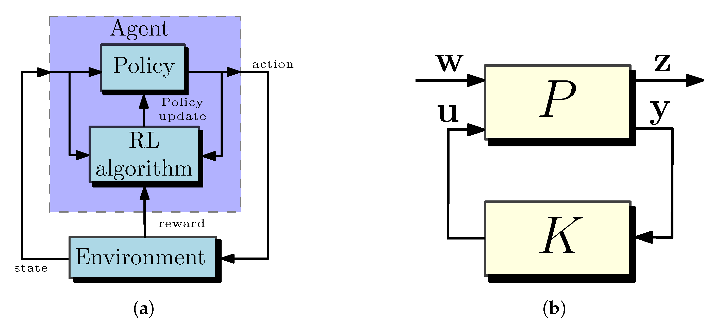
3.4.2. Reinforcement Learning

The last few years have witnessed an enormous interest in the use of artificial intelligence (AI) techniques in different engineering fields. AI has the capability to facilitate systems with intelligence that is capable of human-like learning and reasoning. Among the different categories of AI, machine learning is used primarily in the research of power systems such as electric drives [192]. A general overview about the utilization of AI methods for power electronics systems and electrical drives is given in [192,193], respectively. The machine learning techniques used to control or monitoring electrical drives are summarized in [194].
Reinforcement learning (RL), which is an area of machine learning, can be considered as a viable solution to many decision and control problems across different time scales. Model-free RL based methods are data-driven techniques, which do not require an explicit plant model like most of the approaches overviewed in this paper. Instead, the control policy is continuously improved solely based on measurement feedback, pursuing optimal control performance through learning [195]. Per definition, RL methods use an agent acting in an environment. The schematic structure of an RL agent can be see in Figure 12a. For an electric drive, the environment is the VSI-fed machine with sensor signals, while the agent is a digital device with the capability to control the VSI and read the sensor signals. At a given time instant, the agent observes the state of the environment and decides on an action that changes the state. For each action, the agent is given a reward signal. The role of the agent is to maximize the total received reward [196]. The agent has two main components: a policy and a learning algorithm. The policy maps the state of the environment to a probability distribution of the actions to be taken. It has tunable parameters, which are updated by the learning algorithm. Learning algorithms utilize parameterized approximators for training the policy. They can de divided as critics and actors. Critics predict the cumulative long-term reward for a given state and action. Actors specify the action for a given state, which maximizes cumulative long-term rewards.
Model-free RL algorithms can be classified in three categories, namely value-based methods, policy-based methods and actor–critic methods [197]. Value-based methods, which use only critics, try to find the expected aggregate reward for all possible control inputs at the same time, and then the optimal control action by choosing the control action having maximum reward. In the case of a finite number of control signals, like voltage vectors of VSI, the concept of the method is similar to FS-MPC approaches. Policy-based methods, which use only actors, are explicit methods, where the control action is directly calculated. Policy-based methods are able to handle continuous state and action spaces. Actor–critic methods can be assumed as the combination of value-based and policy-based methods, which can handle both discrete and continuous action spaces.
Article [197] was the first to use an RL-based current control using the actor–critic method for an electrical drive (surface-mounted PMSM). The results are verified by simulation. Several modifications and improvements for the training of RL methods are suggested in [195]. Furthermore, a rapid control prototyping toolchain is introduced, allowing for fast and flexible testing of arbitrary RL algorithms. The contributions of the paper are verified by experimental results as well. An open-source Python package gym-electric-motor (GEM), developed for the ease of training RL agents for electric motor control, is presented in [198]. In paper [199], the conventional linear PI controllers in FOC are replaced by RL-based controllers. The simulation study proves that the RL-based solution has better dynamic performance and eliminates the problem caused by the decoupling for current control.
The RL method is adopted to control an IPMSM using H -synthesis (see next section) in [200]. A meta RL approach is introduced in [201], which uses the control of a large number of PMSM drives from a few watts up to hundreds of kilowatts. As a result, the RL-based control algorithm has the capability to adapt itself for a given drive system without the need for individual training, which drastically reduces the time for the training.
The application of RL methods is extremely computationally demanding, which requires high-end—and most likely, very costly—digital hardware. Since price is an important consideration in industrial applications, the spread of RL-based methods is still waiting to be applied in practical drives. Most likely, field-programmable gate array system-on-chip (FPGA SoC) can be a cost-effective suitable embedded system for the implementation of these techniques [193,194,202]. The current direction of developments predicts that the RL-based data-driven control approach can become a next-generation technology to control electrical drives instead of the classical model-based approaches.

3.5. Robust Controllers

Robust control is an important field of feedback control theory, which is concerned with stability and performance of systems with uncertainties. Robust control is not one controller, but rather a design method.

3.5.1. H -Synthesis Control

One of the most important tools for robust control is H [203]. During the design of H control, the original system model without parameter uncertainty is augmented with certain weighting functions, which express all the control targets. The augmented plant has two inputs: an exogenous input w , which includes the reference signal and/or disturbances; and a control signal u , which is the output of the feedback controller. The augmented plant has also two output signals: the measured or estimated variables y , which are the input of the feedback control; and a so-called evaluation output z , which is used to evaluate the response of the system. A feedback controller should be solved, which guarantees that the closed-loop system is inherently stable and limits the response with the desired level. In other words, the H norm of the transfer function between the reference input of the system and the evaluation output of the system is suppressed below a given constant, denoted typically by γ [204,205]. The graph of the standard definition of the H control problem is given in Figure 12b.
The design process of an H controller for a PMSM machine drive is presented in [206]. The paper develops a linearized model of the drive using the Taylor series and calculates the feedback gains by solving iteratively the algebraic Riccati equation at each control time step. A general design method using H synthesis to calculate controller gains of the linear PID controller, either for speed or current control, is presented in [204]. An H technique is used for tuning the controller gains of linear PI controllers of conventional FOC schemes in papers [207,208]. A speed controller without an inner current loop for PMSM drives is proposed in [183]. The method uses an H feedback controller, a nonlinear torque modulation and a linear parameter-varying H state estimator, which uses only position measurement to obtain full state information (position, velocity, currents), including disturbances. A two-degree-of-freedom H speed control structure for PMSM is introduced in [205]. The scheme utilizes a feedback and a feedforward H controller and a disturbance observer. The current of machine is controlled by linear PI-type controllers. The proposed method has fast, dynamic and strong robustness against the external disturbance, and parameter variation, like changing inertia.

3.5.2. μ -Synthesis Control

The μ -synthesis technique extends the methods of H synthesis to design a robust controller for an uncertain plant. Because the control problem is NP-hard, it is usually solved using an approximation [209]. While μ -synthesis can be considered a compelling solution to obtain excellent performance against parameter uncertainties, there are still only a few studies that apply this concept to control power electronics systems and electrical drives [210].
Paper [210] introduces a current control scheme based on an improved μ -synthesis for a single-phase rectifier in a traction drive system. The paper compares the performance of the proposed scheme with classic PI-based current control as well as conventional μ -synthesis control. It is demonstrated that μ -synthesis has superior performance in terms of robustness and response time compared to linear PI controllers. Furthermore, the proposed scheme has a slightly better performance than conventional μ -synthesis control. Paper [211] presents μ -synthesis to design a robust controller for an IPMSM. The paper approximates the nonlinear system of the machine using a linear system with structured uncertainties according to the geometric structures. The reduced linear model considerably reduces the design effort and the number of required sensors, and simplifies calculation.

3.6. Adaptive Controllers

The controller parameters for adaptive controllers are updated regularly with respect to time. In this paper, two adaptive control approaches, iterative learning control and model reference adaptive control, are discussed in more detail.

3.6.1. Iterative Learning Control

Iterative learning control (ILC) is a technique that utilizes the control experience of the previous iterative cycles at every current iteration cycle. ILC techniques offer a feasible solution to industrial applications, like industrial robots, having a repeatable nature [212]. They can provide rejection against periodic disturbances and an enhanced transient tracking performance. ILC is a widely used approach in IPMSM drive systems, where ripple-free, smooth torque is an essential requirement. The method can minimize the repetitively generated torque pulsations originating from cogging torque, flux harmonics, current offset and deadtime effects [213,214].
Conventionally, the outer speed controller relies on the ILC in parallel with linear PI-type controller (PI-ILC) to compensate the reference current and achieve an impressive torque ripple reduction [214,215]. The inner current loop typically uses a conventional FOC-based scheme with linear PI-type controllers. Conventional PI-ILC is sensitive on system uncertainties and nonperiodic components of the torque ripples. The latter can cause an accumulative effect. To overcome the problem, a forgetting factor is generally utilized in the learning law of ILC [214]. An adaptive ILC using a real-time tuning method for the calculation of the learning gain as well as the forgetting factor is proposed in [216]. Also, an optimization method for the calculation of the parameters of the ILC is introduced in [217]. A robust, adaptive SMC-based speed control combined with ILC is proposed in [218] to alleviate the problem caused by nonperiodic torque components. Also, an SMC-based speed control with ILC is introduced in [219].
Some articles utilize the ILC technique to control the current of the IPMSM as well. An improved ILC scheme for current control is proposed in [220]. In the paper, the ILC control terms is used to enhance the transient performance of the IPMSM drive by updating the control signals according to the preceding input and error signals. An additional feedback and adaptive term are also utilized to improve the steady-state performance and the robustness against parameter variation.

3.6.2. Model Reference Adaptive Control

The model reference adaptive control (MRAC) computes control actions to make an uncertain controlled system track the behavior of a given reference plant model. Typically, the MRAC structure includes three parts: a reference model, an actual plant and an adaptive law, also called an adaptive rate model. MRAC techniques can be classified into direct and indirect methods. In the case of direct MRAC, the feedback and feedforward controller gains are estimated based on the tracking error between the states of the reference model and the controlled system. In the case of indirect MRAC, the parameters of the controlled systems are estimated based on the tracking error between the states of the reference model and the controlled system. The estimated parameters can be used to modify the gains in the control scheme.
A direct MRAC scheme, which updates the gains of the PI controller to control the speed and the current of an IPMSM, is proposed in [221]. Paper [222] applies an MRAC torque loop to improve the performance of the IPMSM drive by following the MTPA curve, even for parameter uncertainties. The speed of the IPMSM is controlled by a PI controller, which outputs a reference torque. The MRAC scheme updates this reference torque value by utilizing a torque estimator.
Typically for the control of IPMSM drives, indirect MRAC methods are applied, and the schemes are utilized to calculate the varying parameters of the machine or unmeasured state variables, like mechanical speed or angle, in the case of a sensorless drive. For these situations, the model reference adaptive algorithm (MRAA) or system (MRAS) namings are applied typically. Paper [223] proposes an MRAS approach to estimate the machine parameters (L d , L q , Ψ PM ) of an IPMSM in real time. The estimated values are used to modify the current reference signals to follow the MTPA curve. The adaptive law is designed by using Popov’s stability theory. MRAS combined with simulated annealing particle swarm optimization is proposed in [224]. The algorithm is able to identify the electrical parameters of the IPMSM by MRAS. The results are used as the initial population in particle swarm optimization identification to further optimize and identify the electrical as well as the mechanical parameters, like J and B. The sensorless FOC control scheme of an IPMSM using MRAS to estimate the speed of the machine is presented in [225]. The stator resistance is also estimated to be able to compensate the effect of its variation at low operating speeds. A sensorless control scheme of an IPMSM, which uses an FLC to control the speed and a FS-MPCC to control the d and q currents, is proposed in [190]. MRAS is utilized to estimate the mechanical speed and angle of the machine. Also, MRAS is used to estimate the speed of an IPMSM in [226] for FOC using linear PI controllers. The control scheme can choose whether to include the integral term of the speed controller depending on the speed error. Furthermore, the estimated speed adaptively adjusts the size of the anti-integration saturation gain to improve the dynamic response.

3.7. Summary

The main goal of the paper is to provide a categorization and a comprehensive review on different control approaches used for the control of current, speed, flux and torque of IPMSM drives. In this section, several techniques are introduced by presenting their basic idea, features and limitations, as well as the proposed improvements and modifications in the literature. Table 2 summarizes the main characteristics of the control strategies presented in the paper.
It should be noted that the table does not contain gain scheduling, as it is not a stand-alone control method and it is typically used together with other control strategies. Furthermore, MRAC is also not included in the table, as for IPMSM, it is typically used either to modify controller gains or estimating machine parameters or unmeasured state variables. H and μ -synthesis are also left out from the table, as they are not controllers, but rather, design methods.
It is important to note that Table 2 lists the benefits and limitations of the control strategies based on their most typical characteristics. As is presented in the paper, many modifications and advancements of the methods have been published in the literature. They can improve the performance of the control technique based on some aspects. For example, using a disturbance observer or online parameter identification method can improve the robustness of PI controller-based schemes against model uncertainties. However, using such techniques drastically increases the computational burden. Also, many methods have been proposed for CS-MPC to reduce the computational burden. As another example, model-free MPC techniques, which were not listed separately in the tables, have much better robustness against parameter mismatch than conventional model-based MPC approaches.
It can be concluded based on the literature that SMC, FLC and ILC approaches, or their combination with each other or with PI-type controllers, can offer a robust performance as an outer speed loop for IPMSM drives. Although the design of these control techniques is complicated and computationally demanding, by following the procedures found in the cited articles, performance with very good transient and steady-state behavior can be obtained. It can be also stated that conventional PI controllers or MPC-based techniques are dominant to control the current or the torque of the machine for industrial drives. Other advanced techniques, like FBL or BS, can also offer a good dynamic performance, but these techniques are currently less widespread. The main reason for this is that no general design guidelines have yet been developed that could be applied for practical drives.
In spite of the significant progress made in the listed control techniques, there are still many open issues to be addressed in the future:
  • Developing general design guidelines for control approaches with higher level of complexity;
  • Incorporating control approaches with disturbance observers, parameter estimation and adaptive control gain tuning;
  • Further reducing computational demand with novel approaches;
  • Investigation and improvements of the performance of the control techniques in the overmodulation region and at low-frequency ratios;
  • Eliminating model dependency by focusing on model-free and data-driven control techniques

4. Reference Calculation Methods

The previous section offers an overview about the different control approaches used to control IPMSM drives. As it was mentioned previously, the reference d and q axis current components, or the reference torque and flux value, should be determined based on the actual operating region of the machine. This section provides a brief overview about the calculation of the reference signals. The reference calculation boxes given in Figure 8 typically have two input signals: the actual electrical angular frequency ω 1 and the reference torque M * , as these two values determine the operating region of the machine.
Below the base speed Ω b , in the constant torque region, typically, the main goal is for the controller to follow the MTPA trajectory, as was discussed previously. The most simple solution is to use the mathematical-model-based (MMB) trajectory tracking method. As the naming convention implies, MMB techniques are mainly based on the mathematical model of the IPMSM, and reference values are obtained in an analytical fashion using similar equations presented for the MTPA trajectory in Table 1. This is a kind of a feedforward (FF) technique: the speed controller dictates the reference torque M * , from which the reference current amplitude i s * can be obtained using the actual electrical frequency as well. By using the analytical equations given in Table 1 the reference i d * and i q * can be calculated. Also, a typical implementation form of this is when the speed loop directly outputs the q axis reference current and only the d axis reference current is calculated analytically [1]. In the case of the DTC-based control scheme (see Figure 8b), the reference flux Ψ s * and reference torque M * can also be determined similarly to follow the MTPA trajectory.
It should be noted that the equation of the MTPA trajectory based on the mathematical model (for example, those which are given in Table 1) is typically written with the assumption of steady-state and negligible winding resistance, such as in paper [40]. Furthermore, the inductances (L d , L q ) and the flux induced by the permanent magnets are considered constant, and the effects of mutual or cross-saturation are not taken into account. While the MMB approach using constant parameters is simple and computation-efficient and provides a good dynamic performance, its robustness is insufficient against changes in machine parameters or against low-speed operation when the stator resistance cannot be neglected [95]. Paper [227] presents a current reference calculation methodology, which takes into account the effect of stator resistance. Modeling issues regarding inductance variations can be addressed either by using LUTs obtained from experimental results or finite element analysis [228], or curve-fitting methods using polynomial approximation [39,229,230] or online parameter estimation [25]. Two LUTs for the calculation of the optimal flux and torque reference signals based on measurement results are introduced for the DTC scheme in [228]. Paper [39] presents a mathematical model of a PMSM with algebraic expressions to account for magnetic saturation using curve fitting. In [230], third-order polynomials are fitted to the flux linkage map over the current plane, which were obtained from finite element analysis methods. Curve fitting was performed using the least-squares method. Furthermore, to account for cross-magnetization, Ferrari’s method was used to extend the accuracy of the proposed MTPA trajectory following method. The approach presented in paper [25] is based on a motor parameter identification technique by taking into account inverter nonlinearities using the recursive least-squares method. The method also considers the derivative terms for the calculation of the MTPA curve by using the identified machine parameters. A novel artificial neural network feedforward strategy is proposed in [36], which allows one to analytically compute the optimal reference currents for IPMSMs with high-operating point-dependent nonlinear electric and magnetic characteristics. A machine learning-based MTPA trajectory following the d axis current reference generation scheme is introduced in [231], along with an SMC-based speed controller.
Signal-injection-based (SIB) trajectory tracking techniques can also be utilized in the MTPA region. The injected signal can be either a high-frequency current or voltage injection; moreover, these signals can be either virtual or real [232,233,234,235]. After signal injection is performed, the MTPA trajectory points can be calculated from either the torque or speed response. The drawback of this tracking strategy is that it can cause torque ripple with significant amplitude, and even the loss of stability, if design guidelines are not followed properly. Furthermore, finding the appropriate signal frequency is problematic, as inverter switching, machine speed, machine inertia, and field vector harmonics all must be considered when selecting the signal frequency. In [232], this process is performed in a self-learning control scheme in the case of a virtual signal injection. A novel scheme, which injects signals into the d and q axis currents and extracts the MTPA indicator from the reconstructed dc-link current, is proposed in [233]. Paper [234] proposes a scheme that inject virtual constant signals. The proposed scheme can avoid the use of filters, which are typical in conventional signal injection schemes. The proposed scheme can be applied not only in MTPA, but also in the FW region. An SIB method using two randomly injected sinusoidal signals at two different frequencies is proposed in [235].
Searching-method-based (SMB) trajectory tracking can also be a viable solution for the calculation of the reference signals thanks to the drastic increase in the computing power of embedded devices. This method searches for intersection points of the current circles and the torque hyperbolas in the MTPA region [38,41,236,237]. Most commonly, gradient-based methods like the Newton–Raphson minimum searching technique are used, which converge quickly to the solution. In paper [41], an SMB methodology is presented using a second-order Newton–Raphson method to numerically solve the trajectory intersection equations. The proposed method accounts for resistive voltage losses within the searching algorithm equations. The model-based equations are updated online. Furthermore, the magnetic saturation (L d L q ) is considered with LUTs with small sampling numbers, which are enhanced with a second-order bilinear interpolation method to ensure accuracy while saving memory space. An SMB method, where the trajectory intersects are computed analytically by solving the quadric equations and reducing them to cubic, online solvable equations is proposed in [38]. In their models, they account for all operation regions as well as for stator resistance and mutual and cross-coupling inductances. Paper [237] introduces a novel SMB method based on gradient descent search along the MTPA trajectory extended with a projection algorithm. In the FW operation region, when reference currents exceed the current limitation along the MTPA trajectory, the MTPA working point is projected to the limit circle. The article accounts for resistive voltage drop and inductance change in different working points. An online optimal tracking method for IPMSM drives, where magnetic core saturation is considered with a mathematical formulation, is introduced in [236]. The mathematical model for the trajectories contains the partial current derivatives of the inductances as well.
Above the base speed Ω b , the IPMSM operates in the FW region. Here, great attention must be paid to the fact that the drive can work on the voltage and/or current limit. In the case of improperly chosen reference signals, the machine will not be able to track them, which can deteriorate the performance of the drive. Paper [1] reviews the commonly used FW methodologies in EV applications. The paper separates FW methods into two groups: feedback and feedforward strategies. A comparative analysis between feedback and feedforward methodologies is also presented in [238] for EV applications. The paper compared these traditional methodologies with a safety-related dead-zone extension of the logics. The main goal of the modification is to improve torque transition dynamics to avoid unwanted braking. The paper concluded that the feedforward-based methodology yielded better torque performance, and the constant power range was better utilized with it.
The feedforward strategies presented previously, like MMB, SIB using virtual signals or SMB techniques, can be also used in this region. The previously cited articles utilizing MMB, SIB with virtual signals or SMB methods typically demonstrate the feasibility of the proposed scheme, even in the FW region.
Feedback-based FW strategies most commonly use current and/or voltage feedback (see dashed lines in Figure 8) to modify the d and q reference current appropriately, as was given in papers [38,239,240]. It should be noted that most commonly, feedback methods are combined with the feedforward technique, which can be assumed as a hybrid technique. In this case, the feedforward technique is utilized to generate the reference signals by using the equation of MTPA or MTPV trajectories, and the feedback method modifies them to ensure proper operation, even in the FW region.
The most commonly used feedback strategy for industrial applications for reference current generation is when the voltage magnitude is regulated [1,241,242]. In this case, the amplitude of the voltage vector setpoint, which is generated by the inner (current) control loop, is subtracted from the maximum allowable voltage V s , max . The differences between them are fed to a linear PI type controller, whose output modifies a selected variable. There are three options: either to modify the d or q axis reference current, or the angle of the reference current vector calculated analytically using the equation of the MTPA or MPTV trajectory from the torque reference. This feedback strategy results in the reference voltage provided by the current loop not exceeding the allowable value. It should be noted that the calculated d and q axis current references should be limited, so as not to exceed the value of I s , max .
Paper [241] presents a. FW strategy based on the conventional MMB-based MTPA trajectory generation, where the d axis reference current is modified according to voltage feedback. The modified reference d axis current then limits the q axis reference current. Paper [242] proposes a scheme where the MTPA and MTPV reference trajectories are generated in a polar coordinate system. In their work, the control strategy is expanded upon with a speed limitation provided by a cruise speed limiter. The FW strategy to generate the reference current utilizes voltage feedback that modifies the angle of the reference current vector. The authors of [242] conclude that the current angle modification is beneficial, as it only grows if speed grows, making transition smooth between MTPA and FW operation. A current reference calculation in a FW region scheme based on voltage feedback, where the d axis reference current is defined from the voltage feedback loop and the reference stator current, is proposed in [240]. This current is saturated, and the difference before and after the saturation is used to adjust the q axis current accordingly. A machine learning-based d axis current reference calculation scheme is introduced in [231], even for the FW region. In this paper, the voltage feedback modifies the q axis reference current.
Figure 13 shows the collective of the methods briefly discussed above.

5. Conclusions, Future Trends

The main purpose of this article is to systematize and present the different control techniques used in IPMSM drives. The control approaches have been grouped as linear, nonlinear, model predictive, robust, intelligent and adaptive control techniques. The operational principles, advantages and limitations of each method are summarized. Furthermore, the latest improvements are presented, which were published in the literature for a given control technique. The paper presents a brief overview about the theoretical background, and presents recent trends in the fields, including motor construction, mathematical modeling and operation regions of IPMSMs, voltage source inverters and reference calculation methods.
The continuous development of control techniques, the optimization of stator and rotor construction and further improvements in power electronics devices and converter topologies can contribute to obtain better-quality IPMSM drives.
Although this was not the primary goal of the article, it can be stated in connection with the optimization of motor construction that there is a clear trend to find alternatives to RE materials for cost reduction and efficiency improvement purposes. Furthermore, the new optimization techniques based on genetic algorithms and finite element simulation can contribute to further improvements in the performance, torque capability and efficiency of IPMSMs applied in traction drives. The application of wide-bandgap semiconductors in VSIs can increase the efficiency of the drive train and allow for the operation of the machines at higher fundamental frequencies in the FW region, even at good harmonic performance.
Regarding the control techniques, it can be stated that model-based methods dominate in the case of traction drives used today. Among these, the classic linear PI-type controller-based vector control and MPC techniques are the most commonly used approaches for current control. SMC, FCL and ILC are receiving increasing attention as the speed controller loop instead of the classic PI-type controllers. The parameter mismatches and external disturbances can deteriorate the performance of model-based solutions. However, the combination of the control approaches with different observer techniques and/or online parameter identification can minimize the effect of this limitation.
Another approach to enhance the robustness of model-based techniques is to avoid the use of the machine parameters and to use model-free, data-driven techniques. Although model-free approaches, like MPC and RL-based control strategies, have a higher computational burden than classic techniques, the current direction of developments predicts that these approaches can become a next-generation technology to control IPMSM drives instead of the classical model-based approaches.
The quality of control techniques used for IPMSM drives is closely related to the reference signal generation method as well. As was presented in this paper, the SMB trajectory tracking method or SIB with virtual signals can be viable solutions both in the MTPA or FW region to generate the reference signals for the current loop. Further developments may contribute to an even wider spread of these methods.

Author Contributions

There was an equal contribution by the authors. All authors have read and agreed to the published version of the manuscript.

Funding

The research reported in this paper is part of project no. BME-NVA-02, implemented with the support provided by the Ministry of Innovation and Technology of Hungary from the National Research, Development and Innovation Fund, financed under the TKP2021 funding scheme. This work was supported by the National Research, Development, and Innovation Office (NKFIH) under Grant FK 143429.

Data Availability Statement

No new data were created or analyzed in this study. Data sharing is not applicable to this article.

Conflicts of Interest

The authors declare no conflict of interest.

Abbreviations

The following abbreviations are used in this manuscript:
2L-VSITwo-Level VSI
AIArtificial Intelligence
CS-MPCContinuous Set Model Predictive Control
DTCDirect Torque Control
EVElectric Vehicle
FBLFeedback Linearization
FBFeedback
FFFeedforward
FLCFuzzy Logic Control
FOCField Oriented Control
FSCWFractional-Slot Concentrated Winding
FS-MPCFinite Set Model Predictive Control
FWField Weakening
HCHysteresis Control
HEPMa-SynRMHybrid-Excited Permanent-Magnet-Assisted SynRM
HE-PMSMHybrid-Excited PMSM
HEVHybrid Electric Vehicle
ILCIterative Learning Controller
IPMSMInterior Permanent-Magnet Synchronous Machine
ISDWInteger-Slot Distributed Winding
LQRLinear Quadratic Regulator
LUTLookup table
MCMaximum Current
ML-VSIMultilevel Voltage Source Inverter
MMBMathematical-Model-Based
MPCModel Predictive Control
MPCCModel Predictive Current Control
MPTCModel Predictive Torque Control
MRAAModel Reference Adaptive Algorithm
MTPAMaximum Torque Per Ampere
MTPCMaximum Torque Per Current
MTPFMaximum Torque Per Flux
MTPVMaximum Torque Per Voltage
PCPredictive Control
PDBCPredictive Deadbeat Control
PIProportional-Integral
PMPermanent Magnet
PMa-SynRMPermanent-Magnet-Assisted SynRM
PMSMPermanent-Magnet Synchronous Machine
PWMPulse Width Modulation
RERare-Earth
RLReinforcement Learning
RRFRotating Reference Frame
SFCState Feedback Control
SIBSignal-Injection-Based
SMSynchronous Machine
SMBSearching-Method-Based
SMCSliding Mode Control
SPSalient Pole
SRFStationary Reference Frame
SVMSpace Vector Modulation
SynRMSynchronous Reluctance Machine
THDTotal Harmonic Distortion
VEVoltage Ellipse
VSIVoltage Source Inverter
WRSMWound Rotor Synchronous Machine

References

  1. Miguel-Espinar, C.; Heredero-Peris, D.; Villafafila-Robles, R.; Montesinos-Miracle, D. Review of Flux-Weakening Algorithms to Extend the Speed Range in Electric Vehicle Applications with Permanent Magnet Synchronous Machines. IEEE Access 2023, 11, 22961–22981. [Google Scholar] [CrossRef]
  2. Hussain, A.; Baig, Z.; Toor, W.T.; Ali, U.; Idrees, M.; Shloul, T.A.; Ghadi, Y.Y.; Alkahtani, H.K. Wound Rotor Synchronous Motor as Promising Solution for Traction Applications. Electronics 2022, 11, 4116. [Google Scholar] [CrossRef]
  3. Murataliyev, M.; Degano, M.; Di Nardo, M.; Bianchi, N.; Gerada, C. Synchronous Reluctance Machines: A Comprehensive Review and Technology Comparison. Proc. IEEE 2022, 110, 382–399. [Google Scholar] [CrossRef]
  4. Jahns, T.M.; Kliman, G.B.; Neumann, T.W. Interior Permanent-Magnet Synchronous Motors for Adjustable-Speed Drives. IEEE Trans. Ind. Appl. 1986, IA-22, 738–747. [Google Scholar] [CrossRef]
  5. Fontana, M.; Bianchi, N. Design and Analysis of Normal Saliency IPM Spoke Motor. IEEE Trans. Ind. Appl. 2020, 56, 3625–3635. [Google Scholar] [CrossRef]
  6. Khatab, M.F.H.; Zhu, Z.Q.; Li, H.Y.; Liu, Y. Comparative study of novel axial flux magnetically geared and conventional axial flux permanent magnet machines. CES Trans. Electr. Mach. Syst. 2018, 2, 392–398. [Google Scholar] [CrossRef]
  7. Wu, F.; EL-Refaie, A.M. Permanent Magnet Vernier Machines: A Review. In Proceedings of the 2018 XIII International Conference on Electrical Machines (ICEM), Alexandroupoli, Greece, 3–6 September 2018; pp. 372–378. [Google Scholar] [CrossRef]
  8. Cinti, L.; Bianchi, N. Hybrid-Excited PM Motor for Electric Vehicle. Energies 2021, 14, 916. [Google Scholar] [CrossRef]
  9. Huynh, T.A.; Hsieh, M.F. Performance Analysis of Permanent Magnet Motors for Electric Vehicles (EV) Traction Considering Driving Cycles. Energies 2018, 11, 1385. [Google Scholar] [CrossRef] [Green Version]
  10. Wardach, M.; Prajzendanc, P.; Palka, R.; Cierzniewski, K.; Pstrokonski, R.; Cichowicz, M.; Pacholski, S.; Ciurus, J.; Hao, C. Hybrid-Excited Permanent Magnet-Assisted Synchronous Reluctance Machine. Energies 2022, 15, 2997. [Google Scholar] [CrossRef]
  11. Abhijith, V.; Hossain, M.J.; Lei, G.; Sreelekha, P.A.; Monichan, T.P.; Rao, S.V. Hybrid Switched Reluctance Motors for Electric Vehicle Applications with High Torque Capability without Permanent Magnet. Energies 2022, 15, 7931. [Google Scholar] [CrossRef]
  12. Cui, W.; Wang, D.; Ren, L.; Zhang, Y. A New Optimized IPMSM for EVs with Reduced Magnet Loss for Over-Modulation Operation. IEEE Trans. Magn. 2023, 59, 8200104. [Google Scholar] [CrossRef]
  13. Ahsanullah, K.; Dutta, R.; Rahman, M. Distributed and concentrated winding Interior PM Synchronous Machine (IPMSM) for direct drive wind turbine. In Proceedings of the 39th Annual Conference of the IEEE Industrial Electronics Society (IECON 2013), Vienna, Austria, 10–13 November 2013; pp. 2762–2767. [Google Scholar] [CrossRef]
  14. Mukundan, S.; Dhulipati, H.; Li, Z.; Toulabi, M.S.; Tjong, J.; Kar, N.C. Coupled Magnetic Circuit-Based Design of an IPMSM for Reduction of Circulating Currents in Asymmetrical Star-Delta Windings. IEEE Trans. Transp. Electrif. 2022, 8, 2971–2984. [Google Scholar] [CrossRef]
  15. Song, P.; Toulabi, M.S.; Li, W.; Mukundan, S.; Byczynski, G.; Tjong, J.; Kar, N.C. Improvement of Electromagnetic Force and Acceleration in an Asymmetrical Star-Delta Winding IPMSM through Stator and Rotor Geometrical Modifications. In Proceedings of the 47th Annual Conference of the IEEE Industrial Electronics Society (IECON 2021), Toronto, ON, Canada, 13–16 October 2021; pp. 1–6. [Google Scholar] [CrossRef]
  16. Islam, M.S.; Husain, I.; Ahmed, A.; Sathyan, A. Asymmetric Bar Winding for High-Speed Traction Electric Machines. IEEE Trans. Transp. Electrif. 2020, 6, 3–15. [Google Scholar] [CrossRef]
  17. Liu, X.; Chen, H.; Zhao, J.; Belahcen, A. Research on the Performances and Parameters of Interior PMSM Used for Electric Vehicles. IEEE Trans. Ind. Electron. 2016, 63, 3533–3545. [Google Scholar] [CrossRef]
  18. Oh, S.Y.; Cho, S.Y.; Han, J.H.; Lee, H.J.; Ryu, G.H.; Kang, D.; Lee, J. Design of IPMSM Rotor Shape for Magnet Eddy-Current Loss Reduction. IEEE Trans. Magn. 2014, 50, 841–844. [Google Scholar] [CrossRef]
  19. Tahanian, H.; Aliahmadi, M.; Faiz, J. Ferrite Permanent Magnets in Electrical Machines: Opportunities and Challenges of a Non-Rare-Earth Alternative. IEEE Trans. Magn. 2020, 56, 900120. [Google Scholar] [CrossRef]
  20. Cui, W.; Ren, L.; Zhou, J.; Zhang, Q. A New IPMSM With Hybrid Rotor Structure for Electrical Vehicle with Reduced Magnet Loss. IEEE Trans. Magn. 2022, 58, 8700406. [Google Scholar] [CrossRef]
  21. Xu, R.; Tong, W. Multi-objective Hierarchical Optimization of Interior Permanent Magnet Synchronous Machines Based on Rotor Surface Modification. CES Trans. Electr. Mach. Syst. 2022, 6, 352–358. [Google Scholar] [CrossRef]
  22. Liang, X.; Liu, F.; Li, W.; Wang, M.; Zheng, P.; Gu, Z. A Novel Rotor Re-Construction Method for Improving the Electromagnetic Performance of the Interior PMSM. In Proceedings of the 2022 25th International Conference on Electrical Machines and Systems (ICEMS), Chiang Mai, Thailand, 29 November–2 December 2022; pp. 1–4. [Google Scholar] [CrossRef]
  23. Krause, P.; Wasynczuk, O.; Sudhoff, S.; Pekarek, S. Analysis of Electric Machinery and Drive Systems, 3rd ed.; Wiley: Hoboken, NJ, USA, 2013. [Google Scholar] [CrossRef]
  24. Mubarok, M.S.; Liu, T.H. An Adjustable Wide-Range Speed-Control Method for Sensorless IPMSM Drive Systems. IEEE Access 2022, 10, 42727–42738. [Google Scholar] [CrossRef]
  25. Yang, R.; Sun, T.; Feng, W.; He, S.; Zhu, S.; Chen, X. Accurate online MTPA control of IPMSM considering derivative terms. Chin. J. Electr. Eng. 2021, 7, 100–110. [Google Scholar] [CrossRef]
  26. Li, S.; Sarlioglu, B.; Jurkovic, S.; Patel, N.R.; Savagian, P. Analysis of Temperature Effects on Performance of Interior Permanent Magnet Machines for High Variable Temperature Applications. IEEE Trans. Ind. Appl. 2017, 53, 4923–4933. [Google Scholar] [CrossRef]
  27. Muazzam, H.; Ishak, M.K.; Hanif, A.; Bhatti, A.I. Compensating Thermal Derated Torque of IPMSM Centric Electric Vehicles. IEEE Access 2022, 10, 24468–24480. [Google Scholar] [CrossRef]
  28. Englert, T.; Graichen, K. Nonlinear model predictive torque control of PMSMs for high performance applications. Control Eng. Pract. 2018, 81, 43–54. [Google Scholar] [CrossRef]
  29. Elsherbiny, H.; Szamel, L.; Ahmed, M.K.; Elwany, M.A. High Accuracy Modeling of Permanent Magnet Synchronous Motors Using Finite Element Analysis. Mathematics 2022, 10, 3880. [Google Scholar] [CrossRef]
  30. Watthewaduge, G.; Toulabi, M.S.; Filizadeh, S.; Gole, A.M. Performance Analysis and Operating Limits of a Dual-Inverter Open-Winding IPMSM Drive. IEEE Trans. Energy Convers. 2019, 34, 1655–1666. [Google Scholar] [CrossRef]
  31. Englert, T.; Graichen, K. A Fixed-Point Iteration Scheme for Model Predictive Torque Control of PMSMs. IFAC-PapersOnLine 2018, 51, 568–573. [Google Scholar] [CrossRef]
  32. Fasil, M.; Antaloae, C.; Mijatovic, N.; Jensen, B.B.; Holboll, J. Improved dq-Axes Model of PMSM Considering Airgap Flux Harmonics and Saturation. IEEE Trans. Appl. Supercond. 2016, 26, 5202705. [Google Scholar] [CrossRef] [Green Version]
  33. Di Tommaso, A.O.; Miceli, R.; Nevoloso, C.; Scaglione, G.; Schettino, G. Improved High-Fidelity IPMSM mathematical model Including Saturation, Cross-Coupling, Torque Ripple and Iron Loss effects. In Proceedings of the 2022 International Conference on Electrical Machines (ICEM), Valencia, Spain, 5–8 September 2022; pp. 21–27. [Google Scholar] [CrossRef]
  34. Seilmeier, M.; Ebersberger, S.; Piepenbreier, B. PMSM model for sensorless control considering saturation induced secondary saliencies. In Proceedings of the 2013 IEEE International Symposium on Sensorless Control for Electrical Drives and Predictive Control of Electrical Drives and Power Electronics (SLED/PRECEDE), Munich, Germany, 17–19 October 2013; pp. 1–8. [Google Scholar] [CrossRef]
  35. Cai, H.; Hu, D. On PMSM Model Fidelity and its Implementation in Simulation. In Proceedings of the 2018 IEEE Energy Conversion Congress and Exposition (ECCE), Portland, OR, USA, 23–27 September 2018; pp. 1674–1681. [Google Scholar] [CrossRef]
  36. Buettner, M.A.; Monzen, N.; Hackl, C.M. Artificial Neural Network Based Optimal Feedforward Torque Control of Interior Permanent Magnet Synchronous Machines: A Feasibility Study and Comparison with the State-of-the-Art. Energies 2022, 15, 1838. [Google Scholar] [CrossRef]
  37. Bianchi, N. Chapter 6—Permanent Magnet Synchronous Motors. In Power Electronics and Motor Drives; Bogdan, M., Wilamowski, J.d.I., Eds.; CRC Press: Boca Raton, FL, USA, 2010; pp. 1–42. [Google Scholar]
  38. Eldeeb, H.; Hackl, C.M.; Horlbeck, L.; Kullick, J. A unified theory for optimal feedforward torque control of anisotropic synchronous machines. Int. J. Control 2018, 91, 2273–2302. [Google Scholar] [CrossRef] [Green Version]
  39. Inoue, T.; Inoue, Y.; Morimoto, S.; Sanada, M. Mathematical Model for MTPA Control of Permanent-Magnet Synchronous Motor in Stator Flux Linkage Synchronous Frame. IEEE Trans. Ind. Appl. 2015, 51, 3620–3628. [Google Scholar] [CrossRef]
  40. Morimoto, S.; Sanada, M.; Takeda, Y. Wide-speed operation of interior permanent magnet synchronous motors with high-performance current regulator. IEEE Trans. Ind. Appl. 1994, 30, 920–926. [Google Scholar] [CrossRef]
  41. Wang, S.; Kang, J.; Degano, M.; Galassini, A.; Gerada, C. An Accurate Wide-Speed Range Control Method of IPMSM Considering Resistive Voltage Drop and Magnetic Saturation. IEEE Trans. Ind. Electron. 2020, 67, 2630–2641. [Google Scholar] [CrossRef]
  42. Zhang, Z.; Nahid-Mobarakeh, B.; Emadi, A. A Simplified Space Vector Overmodulation Strategy for PMSM Drive System. In Proceedings of the 48th Annual Conference of the IEEE Industrial Electronics Society (IECON 2022), Brussels, Belgium, 17–20 October 2022; pp. 1–7. [Google Scholar] [CrossRef]
  43. Park, H.J.; Ahn, H.W.; Go, S.C. A Study on Performance and Characteristic Analysis According to the Operating Point of IPMSM Drive. Energies 2023, 16, 1219. [Google Scholar] [CrossRef]
  44. Holtz, J. Advanced PWM and Predictive Control—An Overview. IEEE Trans. Ind. Electron. 2016, 63, 3837–3844. [Google Scholar] [CrossRef]
  45. Kumar, K.; Santra, S.B. Performance Analysis of a Three-Phase Propulsion Inverter for Electric Vehicles Using GaN Semiconductor Devices. IEEE Trans. Ind. Appl. 2018, 54, 6247–6257. [Google Scholar] [CrossRef]
  46. Han, D.; Li, S.; Wu, Y.; Choi, W.; Sarlioglu, B. Comparative Analysis on Conducted CM EMI Emission of Motor Drives: WBG Versus Si Devices. IEEE Trans. Ind. Electron. 2017, 64, 8353–8363. [Google Scholar] [CrossRef]
  47. Thao, N.G.M.; Naruse, K.; Fujisaki, K. Reduction of Harmonics and Inverter Temperature in Experimental GaN-based Motor Drive System at High Frequencies Using LC Filter. In Proceedings of the 2022 IEEE Ninth International Conference on Communications and Electronics (ICCE), Nha Trang City, Vietnam, 27–29 July 2022; pp. 507–512. [Google Scholar] [CrossRef]
  48. Costa, P.; Pinto, S.; Silva, J.F. A Novel Analytical Formulation of SiC-MOSFET Losses to Size High-Efficiency Three-Phase Inverters. Energies 2023, 16, 818. [Google Scholar] [CrossRef]
  49. Hakami, S.S.; Lee, K.B. Four-Level Hysteresis-Based DTC for Torque Capability Improvement of IPMSM Fed by Three-Level NPC Inverter. Electronics 2020, 9, 1558. [Google Scholar] [CrossRef]
  50. Alsofyani, I.M.; Halabi, L.M. Unidirectional Finite Control Set-Predictive Torque Control of IPMSM Fed by Three-Level NPC Inverter with Simplified Voltage-Vector Lookup Table. Electronics 2023, 12, 252. [Google Scholar] [CrossRef]
  51. Bouarfa, A.; Bodson, M.; Fadel, M. A fast active-balancing method for the 3-phase multilevel flying capacitor inverter derived from control allocation theory. IFAC-PapersOnLine 2017, 50, 2113–2118. [Google Scholar] [CrossRef]
  52. Schettino, G.; Nevoloso, C.; Miceli, R.; Tommaso, A.D.; Viola, F. Impact Evaluation of Innovative Selective Harmonic Mitigation Algorithm for Cascaded H-Bridge Inverter on IPMSM Drive Application. IEEE Open J. Ind. Appl. 2021, 2, 347–365. [Google Scholar] [CrossRef]
  53. Eswar, K.N.D.V.S.; Doss, M.A.N.; Vishnuram, P.; Selim, A.; Bajaj, M.; Kotb, H.; Kamel, S. Comprehensive Study on Reduced DC Source Count: Multilevel Inverters and Its Design Topologies. Energies 2023, 16, 18. [Google Scholar] [CrossRef]
  54. Vinay Kumar, N.V.; GowriManohar, T. A comprehensive survey on reduced switch count multilevel inverter topologies and modulation techniques. J. Electr. Syst. Inf. Technol. 2023, 10, 3. [Google Scholar] [CrossRef]
  55. Zhu, C.; Zeng, Z.; Zhao, R. Comprehensive Analysis and Reduction of Torque Ripples in Three-Phase Four-Switch Inverter-Fed PMSM Drives Using Space Vector Pulse-Width Modulation. IEEE Trans. Power Electron. 2017, 32, 5411–5424. [Google Scholar] [CrossRef]
  56. Lu, J.; Hu, Y.; Liu, J. Analysis and Compensation of Sampling Errors in TPFS IPMSM Drives with Single Current Sensor. IEEE Trans. Ind. Electron. 2019, 66, 3852–3855. [Google Scholar] [CrossRef]
  57. Lee, K. Flying Capacitor-Assisted Two-Leg Inverter for Permanent Magnet Synchronous Motor Drive. IEEE J. Emerg. Sel. Top. Power Electron. 2021, 9, 5429–5440. [Google Scholar] [CrossRef]
  58. Zhang, B.; Song, Z.; Liu, S.; Huang, R.; Liu, C. Overview of Integrated Electric Motor Drives: Opportunities and Challenges. Energies 2022, 15, 8299. [Google Scholar] [CrossRef]
  59. Matsumori, H.; Maeda, Y.; Kosaka, T.; Matsui, N.; Saha, S. Dual Inverter-Fed Open Winding IPMSM Drive System for High-Power Premium Class EV. IEEE Trans. Ind. Appl. 2023, 59, 2069–2080. [Google Scholar] [CrossRef]
  60. Kafi, M.R.; Hamida, M.A.; Chaoui, H.; Belkacemi, R. Sliding Mode Self-Sensing Control of Synchronous Machine Using Super Twisting Interconnected Observers. Energies 2020, 13, 4199. [Google Scholar] [CrossRef]
  61. Al-Kaf, H.A.G.; Hakami, S.S.; Lee, K.B. Hybrid Current Controller for Permanent-Magnet Synchronous Motors Using Robust Switching Techniques. IEEE Trans. Power Electron. 2023, 38, 3711–3724. [Google Scholar] [CrossRef]
  62. Bocker, J.; Beineke, S.; Bahr, A. On the control bandwidth of servo drives. In Proceedings of the 2009 13th European Conference on Power Electronics and Applications, Barcelona, Spain, 8–10 September 2009; pp. 1–10. [Google Scholar]
  63. Yepes, A.G.; Vidal, A.; Malvar, J.; López, O.; Doval-Gandoy, J. Tuning Method Aimed at Optimized Settling Time and Overshoot for Synchronous Proportional-Integral Current Control in Electric Machines. IEEE Trans. Power Electron. 2014, 29, 3041–3054. [Google Scholar] [CrossRef]
  64. Diab, A.M.; Bozhko, S.; Guo, F.; Rashed, M.; Buticchi, G.; Xu, Z.; Yeoh, S.S.; Gerada, C.; Galea, M. Fast and Simple Tuning Rules of Synchronous Reference Frame Proportional-Integral Current Controller. IEEE Access 2021, 9, 22156–22170. [Google Scholar] [CrossRef]
  65. Yang, S.M.; Lin, K.W. Automatic Control Loop Tuning for Permanent-Magnet AC Servo Motor Drives. IEEE Trans. Ind. Electron. 2016, 63, 1499–1506. [Google Scholar] [CrossRef]
  66. Yang, S.C.; Hsu, Y.L.; Chou, P.H.; Chen, J.Y.; Chen, G.R. Digital Implementation Issues on High Speed Permanent Magnet Machine FOC Drive Under Insufficient Sample Frequency. IEEE Access 2019, 7, 61484–61493. [Google Scholar] [CrossRef]
  67. Zhu, S.; Huang, W.; Yan, Y.; Niu, Z. High-Damped Complex Vector Current Regulator for PMSM Based on Active Damping Function. IEEE Trans. Power Electron. 2023, 38, 5204–5216. [Google Scholar] [CrossRef]
  68. Vukosavic, S.N.; Peric, L.S.; Levi, E. Digital Current Controller with Error-Free Feedback Acquisition and Active Resistance. IEEE Trans. Ind. Electron. 2018, 65, 1980–1990. [Google Scholar] [CrossRef] [Green Version]
  69. Briz, F.; Degner, M.; Lorenz, R. Analysis and design of current regulators using complex vectors. IEEE Trans. Ind. Appl. 2000, 36, 817–825. [Google Scholar] [CrossRef] [Green Version]
  70. Zhu, Z.Q.; Liang, D.; Liu, K. Online Parameter Estimation for Permanent Magnet Synchronous Machines: An Overview. IEEE Access 2021, 9, 59059–59084. [Google Scholar] [CrossRef]
  71. Liu, X.; Du, Y. Torque Control of Interior Permanent Magnet Synchronous Motor Based on Online Parameter Identification Using Sinusoidal Current Injection. IEEE Access 2022, 10, 40517–40524. [Google Scholar] [CrossRef]
  72. Dang, D.Q.; Rafaq, M.S.; Choi, H.H.; Jung, J.W. Online Parameter Estimation Technique for Adaptive Control Applications of Interior PM Synchronous Motor Drives. IEEE Trans. Ind. Electron. 2016, 63, 1438–1449. [Google Scholar] [CrossRef]
  73. Rafaq, M.S.; Mohammed, S.A.Q.; Jung, J.W. Online Multiparameter Estimation for Robust Adaptive Decoupling PI Controllers of an IPMSM Drive: Variable Regularized APAs. IEEE/ASME Trans. Mechatronics 2019, 24, 1386–1395. [Google Scholar] [CrossRef]
  74. Lin, F.J.; Chen, S.Y.; Lin, W.T.; Liu, C.W. An Online Parameter Estimation Using Current Injection with Intelligent Current-Loop Control for IPMSM Drives. Energies 2021, 14, 8138. [Google Scholar] [CrossRef]
  75. Yang, J.; Chen, W.H.; Li, S.; Guo, L.; Yan, Y. Disturbance/Uncertainty Estimation and Attenuation Techniques in PMSM Drives—A Survey. IEEE Trans. Ind. Electron. 2017, 64, 3273–3285. [Google Scholar] [CrossRef] [Green Version]
  76. Sarsembayev, B.; Suleimenov, K.; Do, T.D. High Order Disturbance Observer Based PI-PI Control System With Tracking Anti-Windup Technique for Improvement of Transient Performance of PMSM. IEEE Access 2021, 9, 66323–66334. [Google Scholar] [CrossRef]
  77. Huber, T.; Peters, W.; Bocker, J. Voltage controller for flux weakening operation of interior permanent magnet synchronous motor in automotive traction applications. In Proceedings of the 2015 IEEE International Electric Machines and Drives Conference (IEMDC), Coeur d’Alene, ID, USA, 10–13 May 2015; pp. 1078–1083. [Google Scholar] [CrossRef]
  78. Brosch, A.; Wallscheid, O.; Böcker, J. Model Predictive Control of Permanent Magnet Synchronous Motors in the Overmodulation Region Including Six-Step Operation. IEEE Open J. Ind. Appl. 2021, 2, 47–63. [Google Scholar] [CrossRef]
  79. Kwon, Y.C.; Kim, S.; Sul, S.K. Six-Step Operation of PMSM with Instantaneous Current Control. IEEE Trans. Ind. Appl. 2014, 50, 2614–2625. [Google Scholar] [CrossRef]
  80. Nakai, H.; Ohtani, H.; Inaguma, Y. Novel Torque Control Technique for High Efficiency/High Power Interior Permanent Magnet Synchronous Motors. R&D Rev. Toyota CRDL 2005, 40, 44–49. [Google Scholar]
  81. Lerdudomsak, S.; Kadota, M.; Doki, S.; Okuma, S. Harmonic Currents Estimation and Compensation Method for Current Control System of IPMSM in Overmodulation Range. In Proceedings of the 2007 Power Conversion Conference, Nagoya, Japan 2–5 April 2007; pp. 1320–1326. [Google Scholar] [CrossRef]
  82. Gemaßmer, T.; Schnarrenberger, M.; Späth, H.; Braun, M. Simple Strategy of Overmodulation in Control of Interior Permanent Magnet Synchronous Machines for Improving Efficiency in Automotive Applications. In Proceedings of the International Exhibition and Conference for Power Electronics, Intelligent Motion, Renewable Energy and Energy Management (PCIM EUROPE 2013), Nuremburg, Germany, 14–16 May 2013; pp. 231–238. [Google Scholar]
  83. Tarczewski, T.; Grzesiak, L.M. Constrained State Feedback Speed Control of PMSM Based on Model Predictive Approach. IEEE Trans. Ind. Electron. 2016, 63, 3867–3875. [Google Scholar] [CrossRef]
  84. Brasel, M. A gain-scheduled multivariable LQR controller for permanent magnet synchronous motor. In Proceedings of the 2014 19th International Conference on Methods and Models in Automation and Robotics (MMAR), Miedzyzdroje, Poland, 2–5 September 2014; pp. 722–725. [Google Scholar] [CrossRef]
  85. Paponpen, K.; Konghirun, M. LQR state feedback controller based on particle swarm optimization for IPMSM drive system. In Proceedings of the 2015 IEEE 10th Conference on Industrial Electronics and Applications (ICIEA), Auckland, New Zealand, 15–17 June 2015; pp. 1175–1180. [Google Scholar] [CrossRef]
  86. Sun, X.; Hu, C.; Lei, G.; Guo, Y.; Zhu, J. State Feedback Control for a PM Hub Motor Based on Gray Wolf Optimization Algorithm. IEEE Trans. Power Electron. 2020, 35, 1136–1146. [Google Scholar] [CrossRef]
  87. Madanzadeh, S.; Abedini, A.; Radan, A.; Ro, J.S. Application of quadratic linearization state feedback control with hysteresis reference reformer to improve the dynamic response of interior permanent magnet synchronous motors. ISA Trans. 2020, 99, 167–190. [Google Scholar] [CrossRef]
  88. Hinkkanen, M.; Asad Ali Awan, H.; Qu, Z.; Tuovinen, T.; Briz, F. Current Control for Synchronous Motor Drives: Direct Discrete-Time Pole-Placement Design. IEEE Trans. Ind. Appl. 2016, 52, 1530–1541. [Google Scholar] [CrossRef] [Green Version]
  89. Matsuki, Y.; Doki, S. High response torque control of IPMSM using state feedback control based on n-t coordinate system. Electr. Eng. Jpn. 2019, 206, 51–62. [Google Scholar] [CrossRef]
  90. Tarczewski, T.; Grzesiak, L.M. An Application of Novel Nature-Inspired Optimization Algorithms to Auto-Tuning State Feedback Speed Controller for PMSM. IEEE Trans. Ind. Appl. 2018, 54, 2913–2925. [Google Scholar] [CrossRef]
  91. Meirinho, C.J.; Bartsch, A.; de Oliveira, J.; Santos Matos Cavalca, M. An optimal MIMO control approach for PMSM drives. In Proceedings of the 2017 Brazilian Power Electronics Conference (COBEP), Juiz de Fora, Brazil, 19–22 November 2017; pp. 1–6. [Google Scholar] [CrossRef]
  92. Xia, C.; Liu, N.; Zhou, Z.; Yan, Y.; Shi, T. Steady-State Performance Improvement for LQR-Based PMSM Drives. IEEE Trans. Power Electron. 2018, 33, 10622–10632. [Google Scholar] [CrossRef]
  93. Wu, C.; Blaabjerg, F. Chapter 1—Advanced control of power electronic systems—An overview of methods. In Control of Power Electronic Converters and Systems; Blaabjerg, F., Ed.; Academic Press: Cambridge, MA, USA, 2021; pp. 1–33. [Google Scholar] [CrossRef]
  94. Aghili, F. Optimal Feedback Linearization Control of Interior PM Synchronous Motors Subject to Time-Varying Operation Conditions Minimizing Power Loss. IEEE Trans. Ind. Electron. 2018, 65, 5414–5421. [Google Scholar] [CrossRef]
  95. Zhou, K.; Ai, M.; Sun, D.; Jin, N.; Wu, X. Field Weakening Operation Control Strategies of PMSM Based on Feedback Linearization. Energies 2019, 12, 4526. [Google Scholar] [CrossRef] [Green Version]
  96. Sun, X.; Xu, N.; Yao, M.; Cai, F.; Wu, M. Efficient feedback linearization control for an IPMSM of EVs based on improved firefly algorithm. ISA Trans. 2023, 134, 431–441. [Google Scholar] [CrossRef]
  97. Choi, Y.S.; Choi, H.H.; Jung, J.W. Feedback Linearization Direct Torque Control with Reduced Torque and Flux Ripples for IPMSM Drives. IEEE Trans. Power Electron. 2016, 31, 3728–3737. [Google Scholar] [CrossRef]
  98. Li, H.; Wang, Z.; Xu, Z.; Wang, X.; Hu, Y. Feedback Linearization Based Direct Torque Control for IPMSMs. IEEE Trans. Power Electron. 2021, 36, 3135–3148. [Google Scholar] [CrossRef]
  99. Choi, A.; Kim, H.; Hu, M.; Kim, Y.; Ahn, H.; You, K. Super-Twisting Sliding Mode Control with SVR Disturbance Observer for PMSM Speed Regulation. Appl. Sci. 2022, 12, 10749. [Google Scholar] [CrossRef]
  100. Liu, X.; Yu, H.; Yu, J.; Zhao, L. Combined Speed and Current Terminal Sliding Mode Control with Nonlinear Disturbance Observer for PMSM Drive. IEEE Access 2018, 6, 29594–29601. [Google Scholar] [CrossRef]
  101. Mani, P.; Rajan, R.; Shanmugam, L.; Joo, Y.H. Adaptive Fractional Fuzzy Integral Sliding Mode Control for PMSM Model. IEEE Trans. Fuzzy Syst. 2019, 27, 1674–1686. [Google Scholar] [CrossRef]
  102. Xu, B.; Shen, X.; Ji, W.; Shi, G.; Xu, J.; Ding, S. Adaptive Nonsingular Terminal Sliding Model Control for Permanent Magnet Synchronous Motor Based on Disturbance Observer. IEEE Access 2018, 6, 48913–48920. [Google Scholar] [CrossRef]
  103. Huang, H.; Tu, Q.; Pan, M.; Jiang, C.; Xue, J. Fast Terminal Sliding Mode Control of Permanent Magnet In-Wheel Motor Based on a Fuzzy Controller. Energies 2020, 13, 188. [Google Scholar] [CrossRef] [Green Version]
  104. Ma, Y.; Li, D.; Li, Y.; Yang, L. A Novel Discrete Compound Integral Terminal Sliding Mode Control with Disturbance Compensation For PMSM Speed System. IEEE/ASME Trans. Mechatron. 2022, 27, 549–560. [Google Scholar] [CrossRef]
  105. Yang, T.; Deng, Y.; Li, H.; Sun, Z.; Cao, H.; Wei, Z. Fast integral terminal sliding mode control with a novel disturbance observer based on iterative learning for speed control of PMSM. ISA Trans. 2023, 134, 460–471. [Google Scholar] [CrossRef]
  106. Li, X.; Liu, J.; Yin, Y.; Zhao, K. Improved Super-Twisting Non-Singular Fast Terminal Sliding Mode Control of Interior Permanent Magnet Synchronous Motor Considering Time-Varying Disturbance of the System. IEEE Access 2023, 11, 17485–17496. [Google Scholar] [CrossRef]
  107. Junejo, A.K.; Xu, W.; Mu, C.; Ismail, M.M.; Liu, Y. Adaptive Speed Control of PMSM Drive System Based a New Sliding-Mode Reaching Law. IEEE Trans. Power Electron. 2020, 35, 12110–12121. [Google Scholar] [CrossRef]
  108. Kim, E.K.; Kim, J.; Nguyen, H.T.; Choi, H.H.; Jung, J.W. Compensation of Parameter Uncertainty Using an Adaptive Sliding Mode Control Strategy for an Interior Permanent Magnet Synchronous Motor Drive. IEEE Access 2019, 7, 11913–11923. [Google Scholar] [CrossRef]
  109. Wang, A.; Jia, X.; Dong, S. A New Exponential Reaching Law of Sliding Mode Control to Improve Performance of Permanent Magnet Synchronous Motor. IEEE Trans. Magn. 2013, 49, 2409–2412. [Google Scholar] [CrossRef]
  110. Wang, A.; Wei, S. Sliding Mode Control for Permanent Magnet Synchronous Motor Drive Based on an Improved Exponential Reaching Law. IEEE Access 2019, 7, 146866–146875. [Google Scholar] [CrossRef]
  111. Wang, Y.; Feng, Y.; Zhang, X.; Liang, J. A New Reaching Law for Antidisturbance Sliding-Mode Control of PMSM Speed Regulation System. IEEE Trans. Power Electron. 2020, 35, 4117–4126. [Google Scholar] [CrossRef]
  112. Hou, Q.; Ding, S.; Yu, X. Composite Super-Twisting Sliding Mode Control Design for PMSM Speed Regulation Problem Based on a Novel Disturbance Observer. IEEE Trans. Energy Convers. 2021, 36, 2591–2599. [Google Scholar] [CrossRef]
  113. Chen, W.H.; Yang, J.; Guo, L.; Li, S. Disturbance-Observer-Based Control and Related Methods—An Overview. IEEE Trans. Ind. Electron. 2016, 63, 1083–1095. [Google Scholar] [CrossRef] [Green Version]
  114. Wang, X.; Reitz, M.; Yaz, E.E. Field Oriented Sliding Mode Control of Surface-Mounted Permanent Magnet AC Motors: Theory and Applications to Electrified Vehicles. IEEE Trans. Veh. Technol. 2018, 67, 10343–10356. [Google Scholar] [CrossRef] [Green Version]
  115. Gabbi, T.S.; de Araujo, M.B.; Rocha, L.R.; Scalcon, F.P.; Gründling, H.A.; Vieira, R.P. Discrete-time sliding mode controller based on backstepping disturbance compensation for robust current control of PMSM drives. ISA Trans. 2022, 128, 581–592. [Google Scholar] [CrossRef]
  116. Rahman, M.; Vilathgamuwa, D.; Uddin, M.; Tseng, K.J. Nonlinear control of interior permanent-magnet synchronous motor. IEEE Trans. Ind. Appl. 2003, 39, 408–416. [Google Scholar] [CrossRef]
  117. Vaidyanathan, S.; Azar, A.T. Chapter 1—An introduction to backstepping control. In Backstepping Control of Nonlinear Dynamical Systems; Vaidyanathan, S., Azar, A.T., Eds.; Advances in Nonlinear Dynamics and Chaos (ANDC); Academic Press: Cambridge, MA, USA, 2021; pp. 1–32. [Google Scholar] [CrossRef]
  118. Wang, W.; Tan, F.; Wu, J.; Ge, H.; Wei, H.; Zhang, Y. Adaptive Integral Backstepping Controller for PMSM with AWPSO Parameters Optimization. Energies 2019, 12, 2596. [Google Scholar] [CrossRef] [Green Version]
  119. Xu, Y.; Lei, Y.; Sha, D. Backstepping direct torque control of permanent magnet synchronous motor with RLS parameter identification. In Proceedings of the 2014 17th International Conference on Electrical Machines and Systems (ICEMS), Hangzhou, China, 22–25 October 2014; pp. 573–578. [Google Scholar] [CrossRef]
  120. Salah, N.; Samira, B.; Moreau, S. Modified backstepping control of IPMSM: Experimental tests. Proc. Inst. Mech. Eng. Part I 2022, 236, 1590–1602. [Google Scholar] [CrossRef]
  121. Kim, S.K.; Lee, J.S.; Lee, K.B. Offset-Free Robust Adaptive Back-Stepping Speed Control for Uncertain Permanent Magnet Synchronous Motor. IEEE Trans. Power Electron. 2016, 31, 7065–7076. [Google Scholar] [CrossRef]
  122. Sun, X.; Yu, H.; Yu, J.; Liu, X. Design and implementation of a novel adaptive backstepping control scheme for a PMSM with unknown load torque. IET Electr. Power Appl. 2019, 13, 445–455. [Google Scholar] [CrossRef]
  123. Mousavi, M.; Karami, M.; Ahmadi, M. Robust speed controller design for permanent magnet synchronous motor based on gain-scheduled control method via LMI approach. SN Appl. Sci. 2020, 2, 1699. [Google Scholar] [CrossRef]
  124. Lakhe, R.K.; Chaoui, H.; Alzayed, M.; Liu, S. Universal Control of Permanent Magnet Synchronous Motors with Uncertain Dynamics. Actuators 2021, 10, 49. [Google Scholar] [CrossRef]
  125. Lopez-Santos, O.; Dantonio, D.S.; Flores-Bahamonde, F.; Torres-Pinzón, C.A. Chapter 2—Hysteresis control methods. In Multilevel Inverters; Kabalcı, E., Ed.; Academic Press: Cambridge, MA, USA, 2021; pp. 35–60. [Google Scholar] [CrossRef]
  126. Son, D.I.; Han, J.S.; Park, J.S.; Lim, H.S.; Lee, G.H. Performance Improvement of DTC-SVM of PMSM with Compensation for the Dead Time Effect and Power Switch Loss Based on Extended Kalman Filter. Electronics 2023, 12, 966. [Google Scholar] [CrossRef]
  127. Lezana, P.; Norambuena, M.; Aguilera, R.P. Dual-Stage Control Strategy for a Flying Capacitor Converter Based on Model Predictive and Linear Controllers. IEEE Trans. Ind. Inform. 2022, 18, 2203–2212. [Google Scholar] [CrossRef]
  128. Cortes, P.; Kazmierkowski, M.P.; Kennel, R.M.; Quevedo, D.E.; Rodriguez, J. Predictive Control in Power Electronics and Drives. IEEE Trans. Ind. Electron. 2008, 55, 4312–4324. [Google Scholar] [CrossRef]
  129. Rodriguez, J.; Garcia, C.; Mora, A.; Flores-Bahamonde, F.; Acuna, P.; Novak, M.; Zhang, Y.; Tarisciotti, L.; Davari, S.A.; Zhang, Z.; et al. Latest Advances of Model Predictive Control in Electrical Drives—Part I: Basic Concepts and Advanced Strategies. IEEE Trans. Power Electron. 2022, 37, 3927–3942. [Google Scholar] [CrossRef]
  130. Elmorshedy, M.F.; Xu, W.; El-Sousy, F.F.M.; Islam, M.R.; Ahmed, A.A. Recent Achievements in Model Predictive Control Techniques for Industrial Motor: A Comprehensive State of the Art. IEEE Access 2021, 9, 58170–58191. [Google Scholar] [CrossRef]
  131. Rodriguez, J.; Garcia, C.; Mora, A.; Davari, S.A.; Rodas, J.; Valencia, D.F.; Elmorshedy, M.; Wang, F.; Zuo, K.; Tarisciotti, L.; et al. Latest Advances of Model Predictive Control in Electrical Drives—Part II: Applications and Benchmarking with Classical Control Methods. IEEE Trans. Power Electron. 2022, 37, 5047–5061. [Google Scholar] [CrossRef]
  132. Carlet, P.G.; Toso, F.; Favato, A.; Bolognani, S. A speed and current cascade Continuous Control Set Model Predictive Control architecture for synchronous motor drives. In Proceedings of the 2019 IEEE Energy Conversion Congress and Exposition (ECCE), Baltimore, MD, USA, 29 September–3 October 2019; pp. 5682–5688. [Google Scholar] [CrossRef]
  133. Jose Rodriguez, P.C. Predictive Control of Power Converters and Electrical Drives; John Wiley & Sons, Ltd.: Hoboken, NJ, USA, 2012. [Google Scholar] [CrossRef]
  134. Karamanakos, P.; Geyer, T. Guidelines for the Design of Finite Control Set Model Predictive Controllers. IEEE Trans. Power Electron. 2020, 35, 7434–7450. [Google Scholar] [CrossRef]
  135. Hassan, M.; Ge, X.; Woldegiorgis, A.T.; Mastoi, M.S.; Shahid, M.B.; Atif, R.; Shaikh, M.S.; Kumar, S. A look-up table-based model predictive torque control of IPMSM drives with duty cycle optimization. ISA Trans. 2023, 138, 670–686. [Google Scholar] [CrossRef]
  136. Zhang, Y.; Xu, D.; Huang, L. Generalized Multiple-Vector-Based Model Predictive Control for PMSM Drives. IEEE Trans. Ind. Electron. 2018, 65, 9356–9366. [Google Scholar] [CrossRef]
  137. Qu, J.; Jatskevich, J.; Zhang, C.; Zhang, S. Improved multiple vector model predictive torque control of permanent magnet synchronous motor for reducing torque ripple. IET Electr. Power Appl. 2021, 15, 681–695. [Google Scholar] [CrossRef]
  138. Yang, Y.; Wen, H.; Fan, M.; Zhang, X.; He, L.; Chen, R.; Xie, M.; Norambuena, M.; Rodriguez, J. Low Complexity Finite-Control-Set MPC Based on Discrete Space Vector Modulation for T-Type Three-Phase Three-Level Converters. IEEE Trans. Power Electron. 2022, 37, 392–403. [Google Scholar] [CrossRef]
  139. Niu, S.; Luo, Y.; Fu, W.; Zhang, X. An Indirect Reference Vector-Based Model Predictive Control for a Three-Phase PMSM Motor. IEEE Access 2020, 8, 29435–29445. [Google Scholar] [CrossRef]
  140. Lin, H.; Niu, S.; Xue, Z.; Wang, S. A Simplified Virtual-Vector-Based Model Predictive Control Technique with a Control Factor for Three-Phase SPMSM Drives. IEEE Trans. Power Electron. 2023, 38, 7546–7557. [Google Scholar] [CrossRef]
  141. Zhang, G.; Chen, C.; Gu, X.; Wang, Z.; Li, X. An Improved Model Predictive Torque Control for a Two-Level Inverter Fed Interior Permanent Magnet Synchronous Motor. Electronics 2019, 8, 769. [Google Scholar] [CrossRef] [Green Version]
  142. Yang, Q.; Karamanakos, P.; Tian, W.; Gao, X.; Li, X.; Geyer, T.; Kennel, R. Computationally Efficient Fixed Switching Frequency Direct Model Predictive Control. IEEE Trans. Power Electron. 2022, 37, 2761–2777. [Google Scholar] [CrossRef]
  143. Cimini, G.; Bernardini, D.; Levijoki, S.; Bemporad, A. Embedded Model Predictive Control with Certified Real Time Optimization for Synchronous Motors. IEEE Trans. Control. Syst. Technol. 2021, 29, 893–900. [Google Scholar] [CrossRef]
  144. De Martin, I.D.; Pasqualotto, D.; Tinazzi, F. aVsIs: An Analytical-Solution-Based Solver for Model-Predictive Control with Hexagonal Constraints in Voltage-Source Inverter Applications. IEEE Trans. Power Electron. 2022, 37, 14375–14383. [Google Scholar] [CrossRef]
  145. Favato, A.; Carlet, P.G.; Toso, F.; Torchio, R.; Bolognani, S. Integral Model Predictive Current Control for Synchronous Motor Drives. IEEE Trans. Power Electron. 2021, 36, 13293–13303. [Google Scholar] [CrossRef]
  146. Jiang, X.; Yang, Y.; Fan, M.; Ji, A.; Xiao, Y.; Zhang, X.; Zhang, W.; Garcia, C.; Vazquez, S.; Rodriguez, J. An Improved Implicit Model Predictive Current Control with Continuous Control Set for PMSM Drives. IEEE Trans. Transp. Electrif. 2022, 8, 2444–2455. [Google Scholar] [CrossRef]
  147. Bándy, K.; Stumpf, P. Quadratic Regression Model-Based Indirect Model Predictive Control of AC Drives. IEEE Trans. Power Electron. 2022, 37, 13158–13177. [Google Scholar] [CrossRef]
  148. Brosch, A.; Wallscheid, O.; Böcker, J. Torque and Inductances Estimation for Finite Model Predictive Control of Highly Utilized Permanent Magnet Synchronous Motors. IEEE Trans. Ind. Inform. 2021, 17, 8080–8091. [Google Scholar] [CrossRef]
  149. Wang, L.; Tan, G.; Meng, J. Research on Model Predictive Control of IPMSM Based on Adaline Neural Network Parameter Identification. Energies 2019, 12, 4803. [Google Scholar] [CrossRef] [Green Version]
  150. Niu, S.; Luo, Y.; Fu, W.; Zhang, X. Robust Model Predictive Control for a Three-Phase PMSM Motor with Improved Control Precision. IEEE Trans. Ind. Electron. 2021, 68, 838–849. [Google Scholar] [CrossRef]
  151. Ke, D.; Wang, F.; He, L.; Li, Z. Predictive Current Control for PMSM Systems Using Extended Sliding Mode Observer with Hurwitz-Based Power Reaching Law. IEEE Trans. Power Electron. 2021, 36, 7223–7232. [Google Scholar] [CrossRef]
  152. Yang, H.; Zhang, Y.; Shen, W. Predictive Current Control and Field-Weakening Operation of SPMSM Drives without Motor Parameters and DC Voltage. IEEE J. Emerg. Sel. Top. Power Electron. 2022, 10, 5635–5646. [Google Scholar] [CrossRef]
  153. Zhang, Y.; Jin, J.; Huang, L. Model-Free Predictive Current Control of PMSM Drives Based on Extended State Observer Using Ultralocal Model. IEEE Trans. Ind. Electron. 2021, 68, 993–1003. [Google Scholar] [CrossRef]
  154. Zhang, Y.; Wu, Z.; Yan, Q.; Huang, N.; Du, G. An Improved Model-Free Current Predictive Control of Permanent Magnet Synchronous Motor Based on High-Gain Disturbance Observer. Energies 2023, 16, 141. [Google Scholar] [CrossRef]
  155. Rodríguez, J.; Heydari, R.; Rafiee, Z.; Young, H.A.; Flores-Bahamonde, F.; Shahparasti, M. Model-Free Predictive Current Control of a Voltage Source Inverter. IEEE Access 2020, 8, 211104–211114. [Google Scholar] [CrossRef]
  156. Lin, C.K.; Liu, T.H.; Yu, J.t.; Fu, L.C.; Hsiao, C.F. Model-Free Predictive Current Control for Interior Permanent-Magnet Synchronous Motor Drives Based on Current Difference Detection Technique. IEEE Trans. Ind. Electron. 2014, 61, 667–681. [Google Scholar] [CrossRef]
  157. Wei, Y.; Wang, F.; Young, H.; Ke, D.; Rodríguez, J. Autoregressive Moving Average Model-Free Predictive Current Control for PMSM Drives. IEEE J. Emerg. Sel. Top. Power Electron. 2023, 1. [Google Scholar] [CrossRef]
  158. Yang, H.; Li, M.; Zhang, Y.; Xu, A. FCS-MPC for Three-Level NPC Inverter-Fed SPMSM Drives without Information of Motor Parameters and DC Capacitor. IEEE Trans. Ind. Electron. 2023, 1–10. [Google Scholar] [CrossRef]
  159. Carlet, P.G.; Favato, A.; Bolognani, S.; Dörfler, F. Data-Driven Continuous-Set Predictive Current Control for Synchronous Motor Drives. IEEE Trans. Power Electron. 2022, 37, 6637–6646. [Google Scholar] [CrossRef]
  160. Carlet, P.G.; Favato, A.; Torchio, R.; Toso, F.; Bolognani, S.; Dörfler, F. Real-Time Feasibility of Data-Driven Predictive Control for Synchronous Motor Drives. IEEE Trans. Power Electron. 2023, 38, 1672–1682. [Google Scholar] [CrossRef]
  161. Wang, Y.; Huang, S.; Huang, X.; Liao, W.; Zhang, J.; Ma, B. An Angle-Based Virtual Vector Model Predictive Current Control for IPMSM Considering Overmodulation. IEEE Trans. Transp. Electrif. 2023, 1. [Google Scholar] [CrossRef]
  162. Yu, F.; Li, K.; Zhu, Z.; Liu, X. An Over-Modulated Model Predictive Current Control for Permanent Magnet Synchronous Motors. IEEE Access 2022, 10, 40391–40401. [Google Scholar] [CrossRef]
  163. Zhang, Y.; Qi, R. Flux-Weakening Drive for IPMSM Based on Model Predictive Control. Energies 2022, 15, 2543. [Google Scholar] [CrossRef]
  164. Xia, C.; Zhou, Z.; Wang, Z.; Yan, Y.; Shi, T. Computationally efficient multi-step direct predictive torque control for surface-mounted permanent magnet synchronous motor. IET Electr. Power Appl. 2017, 11, 805–814. [Google Scholar] [CrossRef]
  165. Acuna, P.; Rojas, C.A.; Baidya, R.; Aguilera, R.P.; Fletcher, J.E. On the Impact of Transients on Multistep Model Predictive Control for Medium-Voltage Drives. IEEE Trans. Power Electron. 2019, 34, 8342–8355. [Google Scholar] [CrossRef]
  166. Dorfling, T.; Mouton, H.d.T.; Geyer, T. Generalized Model Predictive Pulse Pattern Control Based on Small-Signal Modeling—Part 1: Algorithm. IEEE Trans. Power Electron. 2022, 37, 10476–10487. [Google Scholar] [CrossRef]
  167. Zhang, Y.; Zhang, Z.; Babayomi, O.; Li, Z. Weighting Factor Design Techniques for Predictive Control of Power Electronics and Motor Drives. Symmetry 2023, 15, 1219. [Google Scholar] [CrossRef]
  168. Gong, C.; Hu, Y.; Ma, M.; Gao, J.; Shen, K. Novel Analytical Weighting Factor Tuning Strategy Based on State Normalization and Variable Sensitivity Balance for PMSM FCS-MPTC. IEEE/ASME Trans. Mechatronics 2020, 25, 1690–1694. [Google Scholar] [CrossRef]
  169. Sahin, M. Optimization of Model Predictive Control Weights for Control of Permanent Magnet Synchronous Motor by Using the Multi Objective Bees Algorithm. In Model-Based Control Engineering-Recent Design and Implementations for Varied Applications; IntechOpen: London, UK, 2021. [Google Scholar]
  170. Novak, M.; Xie, H.; Dragicevic, T.; Wang, F.; Rodriguez, J.; Blaabjerg, F. Optimal Cost Function Parameter Design in Predictive Torque Control (PTC) Using Artificial Neural Networks (ANN). IEEE Trans. Ind. Electron. 2021, 68, 7309–7319. [Google Scholar] [CrossRef]
  171. Bándy, K.; Stumpf, P. Finite Set Model Predictive Control of PMSM drives with LC filter using dynamic weighting factor assignment. In Proceedings of the 2022 20th International Conference on Mechatronics—Mechatronika (ME), Pilsen, Czech Republic, 7–9 December 2022; pp. 1–7. [Google Scholar] [CrossRef]
  172. Mei, X.; Zu, R.; Wang, F.; Kennel, R. Variable Cost Functions’ Sequence Design for Model Predictive Control of IPMSM without Weighting Factor. In Proceedings of the 2018 IEEE International Conference on Information and Automation (ICIA), Wuyishan, China, 11–13 August 2018; pp. 500–505. [Google Scholar] [CrossRef]
  173. Xie, H.; Novak, M.; Wang, F.; Dragicevic, T.; Rodríguez, J.; Blaabjerg, F.; Kennel, R.; Heldwein, M.L. Cooperative Decision-making Approach for Multi-objective Finite Control Set Model Predictive Control without Weighting Parameters. IEEE Trans. Ind. Electron. 2023, 1–11. [Google Scholar] [CrossRef]
  174. Norambuena, M.; Rodriguez, J.; Zhang, Z.; Wang, F.; Garcia, C.; Kennel, R. A Very Simple Strategy for High-Quality Performance of AC Machines Using Model Predictive Control. IEEE Trans. Power Electron. 2019, 34, 794–800. [Google Scholar] [CrossRef]
  175. Dai, S.; Wang, J.; Sun, Z.; Chong, E. Deadbeat Predictive Current Control for High-Speed Permanent Magnet Synchronous Machine Drives with Low Switching-To-Fundamental Frequency Ratios. IEEE Trans. Ind. Electron. 2022, 69, 4510–4521. [Google Scholar] [CrossRef]
  176. Wang, Y.; Zhu, Y.; Zhang, X.; Tian, B.; Wang, K.; Liang, J. Antidisturbance Sliding Mode-Based Deadbeat Direct Torque Control for PMSM Speed Regulation System. IEEE Trans. Transp. Electrif. 2021, 7, 2705–2714. [Google Scholar] [CrossRef]
  177. Alexandrou, A.D.; Adamopoulos, N.K.; Kladas, A.G. Development of a Constant Switching Frequency Deadbeat Predictive Control Technique for Field-Oriented Synchronous Permanent-Magnet Motor Drive. IEEE Trans. Ind. Electron. 2016, 63, 5167–5175. [Google Scholar] [CrossRef]
  178. Gu, X.; Li, Y.; Chen, W.; Jin, X. Improved Deadbeat Predictive Control Based Current Harmonic Suppression Strategy for IPMSM. Energies 2022, 15, 3943. [Google Scholar] [CrossRef]
  179. Fan, S.; Zhang, Y.; Jin, J.; Wang, X.; Tong, C. Deadbeat predictive current control of PMSM drives with an adaptive flux-weakening controller. IET Power Electron. 2022, 15, 753–763. [Google Scholar] [CrossRef]
  180. Agoro, S.; Husain, I. Robust Deadbeat Finite-Set Predictive Current Control with Torque Oscillation and Noise Reduction for PMSM Drives. IEEE Trans. Ind. Appl. 2022, 58, 365–374. [Google Scholar] [CrossRef]
  181. Lee, J.S. Stability Analysis of Deadbeat-Direct Torque and Flux Control for Permanent Magnet Synchronous Motor Drives with Respect to Parameter Variations. Energies 2018, 11, 2027. [Google Scholar] [CrossRef] [Green Version]
  182. Ofoli, A.R. Fuzzy-Logic Applications in Electric Drives and Power Electronics. In Power Electronics Handbook, 4th ed.; Rashid, M.H., Ed.; Butterworth-Heinemann: Oxford, UK, 2018; pp. 1221–1243. [Google Scholar] [CrossRef]
  183. Lee, Y.; Lee, S.H.; Chung, C.C. LPV H Control with Disturbance Estimation for Permanent Magnet Synchronous Motors. IEEE Trans. Ind. Electron. 2018, 65, 488–497. [Google Scholar] [CrossRef]
  184. Uddin, M.N.; Rebeiro, R.S. Online Efficiency Optimization of a Fuzzy-Logic-Controller-Based IPMSM Drive. IEEE Trans. Ind. Appl. 2011, 47, 1043–1050. [Google Scholar] [CrossRef]
  185. Wang, C.; Zhu, Z.Q. Fuzzy Logic Speed Control of Permanent Magnet Synchronous Machine and Feedback Voltage Ripple Reduction in Flux-Weakening Operation Region. IEEE Trans. Ind. Appl. 2020, 56, 1505–1517. [Google Scholar] [CrossRef]
  186. Wang, M.S.; Hsieh, M.F.; Lin, H.Y. Operational Improvement of Interior Permanent Magnet Synchronous Motor Using Fuzzy Field-Weakening Control. Electronics 2018, 7, 452. [Google Scholar] [CrossRef] [Green Version]
  187. Liu, T.H.; Chen, Y.; Wu, M.J.; Dai, B.C. Adaptive controller for an MTPA IPMSM drive system without using a high-frequency sinusoidal generator. J. Eng. 2017, 2017, 13–25. [Google Scholar] [CrossRef]
  188. Kakouche, K.; Oubelaid, A.; Mezani, S.; Rekioua, D.; Rekioua, T. Different Control Techniques of Permanent Magnet Synchronous Motor with Fuzzy Logic for Electric Vehicles: Analysis, Modelling, and Comparison. Energies 2023, 16, 3116. [Google Scholar] [CrossRef]
  189. Wang, Z.; Yu, A.; Li, X.; Zhang, G.; Xia, C. A Novel Current Predictive Control Based on Fuzzy Algorithm for PMSM. IEEE J. Emerg. Sel. Top. Power Electron. 2019, 7, 990–1001. [Google Scholar] [CrossRef]
  190. Usama, M.; Kim, J. Improved Self-Sensing Speed Control of IPMSM Drive Based on Cascaded Nonlinear Control. Energies 2021, 14, 2205. [Google Scholar] [CrossRef]
  191. Bouguenna, I.F.; Azaiz, A.; Tahour, A.; Larbaoui, A. Robust neuro-fuzzy sliding mode control with extended state observer for an electric drive system. Energy 2019, 169, 1054–1063. [Google Scholar] [CrossRef]
  192. Zhao, S.; Blaabjerg, F.; Wang, H. An Overview of Artificial Intelligence Applications for Power Electronics. IEEE Trans. Power Electron. 2021, 36, 4633–4658. [Google Scholar] [CrossRef]
  193. Zhang, S. Artificial Intelligence in Electric Machine Drives: Advances and Trends. arXiv 2021, arXiv:2110.05403. [Google Scholar]
  194. Zhang, S.; Wallscheid, O.; Porrmann, M. Machine Learning for the Control and Monitoring of Electric Machine Drives: Advances and Trends. IEEE Open J. Ind. Appl. 2023, 4, 188–214. [Google Scholar] [CrossRef]
  195. Book, G.; Traue, A.; Balakrishna, P.; Brosch, A.; Schenke, M.; Hanke, S.; Kirchgässner, W.; Wallscheid, O. Transferring Online Reinforcement Learning for Electric Motor Control From Simulation to Real-World Experiments. IEEE Open J. Power Electron. 2021, 2, 187–201. [Google Scholar] [CrossRef]
  196. Sutton, R.S.; Barto, A.G. Reinforcement Learning: An Introduction; MIT Press: Cambridge, MA, USA, 2018. [Google Scholar]
  197. Schenke, M.; Kirchgässner, W.; Wallscheid, O. Controller Design for Electrical Drives by Deep Reinforcement Learning: A Proof of Concept. IEEE Trans. Ind. Inform. 2020, 16, 4650–4658. [Google Scholar] [CrossRef]
  198. Traue, A.; Book, G.; Kirchgässner, W.; Wallscheid, O. Toward a Reinforcement Learning Environment Toolbox for Intelligent Electric Motor Control. IEEE Trans. Neural Netw. Learn. Syst. 2022, 33, 919–928. [Google Scholar] [CrossRef]
  199. Jegan, J.; Karuppasamy, I. Simulation and Validation of Permanent Magnet Synchronous Motor Drives Using Reinforcement Learning. In Proceedings of the 2023 IEEE 8th International Conference for Convergence in Technology (I2CT), Mumbai, India, 7–9 April 2023; pp. 1–5. [Google Scholar] [CrossRef]
  200. Yu, Y.; Wang, S.; Du, Y.; Viswanathan, V.; Su, R.; Ramakrishna, S.; Gajanayake, C.; Gupta, A.K. Application of Off-policy Integral Reinforcement Learning for H-infinity, Input Constrained Control of Permanent Magnet Synchronous Machine. In Proceedings of the 2019 IEEE Applied Power Electronics Conference and Exposition (APEC), Anaheim, CA, USA, 17–21 March 2019; pp. 2570–2576. [Google Scholar] [CrossRef]
  201. Jakobeit, D.; Schenke, M.; Wallscheid, O. Meta-Reinforcement-Learning-Based Current Control of Permanent Magnet Synchronous Motor Drives for a Wide Range of Power Classes. IEEE Trans. Power Electron. 2023, 38, 8062–8074. [Google Scholar] [CrossRef]
  202. Dendaluce Jahnke, M.; Cosco, F.; Novickis, R.; Pérez Rastelli, J.; Gomez-Garay, V. Efficient Neural Network Implementations on Parallel Embedded Platforms Applied to Real-Time Torque-Vectoring Optimization Using Predictions for Multi-Motor Electric Vehicles. Electronics 2019, 8, 250. [Google Scholar] [CrossRef] [Green Version]
  203. Ullah, K.; Guzinski, J.; Mirza, A.F. Critical Review on Robust Speed Control Techniques for Permanent Magnet Synchronous Motor (PMSM) Speed Regulation. Energies 2022, 15, 1235. [Google Scholar] [CrossRef]
  204. Ko, P.J.; Tsai, M.C. H Control Design of PID-Like Controller for Speed Drive Systems. IEEE Access 2018, 6, 36711–36722. [Google Scholar] [CrossRef]
  205. Li, L.; Pei, G.; Liu, J.; Du, P.; Pei, L.; Zhong, C. 2-DOF Robust H Control for Permanent Magnet Synchronous Motor with Disturbance Observer. IEEE Trans. Power Electron. 2021, 36, 3462–3472. [Google Scholar] [CrossRef]
  206. Rigatos, G.; Abbaszadeh, M.; Wira, P.; Siano, P. A nonlinear optimal control approach for voltage source inverter-fed three-phase PMSMs. In Proceedings of the 47th Annual Conference of the IEEE Industrial Electronics Society (IECON 2021), Toronto, ON, Canada, 13–16 October 2021; pp. 1–6. [Google Scholar] [CrossRef]
  207. Pohl, L.; Buchta, L. H-infinity tuning technique for PMSM cascade PI control structure. In Proceedings of the 2016 6th IEEE International Conference on Control System, Computing and Engineering (ICCSCE), Penang, Malaysia, 25–27 November 2016; pp. 119–124. [Google Scholar] [CrossRef]
  208. Cai, R.; Zheng, R.; Liu, M.; Li, M. Optimal selection of PI parameters of FOC for PMSM using structured H-synthesis. In Proceedings of the 43rd Annual Conference of the IEEE Industrial Electronics Society (IECON 2017), Beijing, China, 29 October–1 November 2017; pp. 8602–8607. [Google Scholar] [CrossRef]
  209. Mihaly, V.; Susca, M.; Morar, D.; Stanese, M.; Dobra, P. μ-Synthesis for Fractional-Order Robust Controllers. Mathematics 2021, 9, 911. [Google Scholar] [CrossRef]
  210. Liu, H.; Ma, L.; Peng, L.; Song, W.; Cheng, S. Robust current control scheme for single-phase PWM rectifiers based on improved μ-synthesis in electric locomotive. IET Power Electron. 2020, 13, 4068–4078. [Google Scholar] [CrossRef]
  211. Cai, R.; Zheng, R.; Liu, M.; Li, M. Robust Control of PMSM Using Geometric Model Reduction and μ-Synthesis. IEEE Trans. Ind. Electron. 2018, 65, 498–509. [Google Scholar] [CrossRef]
  212. Ahn, H.S.; Chen, Y.; Moore, K.L. Iterative Learning Control: Brief Survey and Categorization. IEEE Trans. Syst. Man, Cybern. Part 2007, 37, 1099–1121. [Google Scholar] [CrossRef]
  213. Rafaq, M.S.; Midgley, W.; Steffen, T. A Review of the State of the Art of Torque Ripple Minimization Techniques for Permanent Magnet Synchronous Motors. IEEE Trans. Ind. Inform. 2023, 1–13. [Google Scholar] [CrossRef]
  214. Qian, W.; Panda, S.; Xu, J.X. Torque ripple minimization in PM synchronous motors using iterative learning control. IEEE Trans. Power Electron. 2004, 19, 272–279. [Google Scholar] [CrossRef]
  215. Xu, J.X.; Panda, S.; Pan, Y.J.; Lee, T.H.; Lam, B. A modular control scheme for PMSM speed control with pulsating torque minimization. IEEE Trans. Ind. Electron. 2004, 51, 526–536. [Google Scholar] [CrossRef]
  216. Toloue, S.F.; Moallem, M. PMSM Torque Ripple Minimization Using an Adaptive Iterative Learning Control. In Proceedings of the 46th Annual Conference of the IEEE Industrial Electronics Society (IECON 2020), Singapore, 18–21 October 2020; pp. 335–340. [Google Scholar] [CrossRef]
  217. Xia, C.; Deng, W.; Shi, T.; Yan, Y. Torque ripple minimization of PMSM using parameter optimization based iterative learning control. J. Electr. Eng. Technol. 2016, 11, 425–436. [Google Scholar] [CrossRef] [Green Version]
  218. Liu, J.; Li, H.; Deng, Y. Torque Ripple Minimization of PMSM Based on Robust ILC Via Adaptive Sliding Mode Control. IEEE Trans. Power Electron. 2018, 33, 3655–3671. [Google Scholar] [CrossRef]
  219. Xia, X.; Zhang, B.; Li, X. High Precision Low-Speed Control for Permanent Magnet Synchronous Motor. Sensors 2020, 20, 1526. [Google Scholar] [CrossRef] [Green Version]
  220. Mohammed, S.A.Q.; Lee, K.B. Improved adaptive iterative learning current control approach for IPMSM drives. J. Power Electron. 2023, 23, 284–295. [Google Scholar] [CrossRef]
  221. Golea, N.; Golea, A.; Kadjoudj, M. Robust MRAC Adaptive Control of PMSM drive under General Parameters Uncertainties. In Proceedings of the 2006 IEEE International Conference on Industrial Technology, Mumbai, India, 15–17 December 2006; pp. 1533–1537. [Google Scholar] [CrossRef]
  222. Amornwongpeeti, S.; Kiselychnyk, O.; Wang, J.; Shah, N.; Soumelidis, M. Speed control of IPMSM motor drives using Model Reference Adaptive technique. In Proceedings of the 2017 International Conference on Applied System Innovation (ICASI), Sapporo, Japan, 13–17 May 2017; pp. 672–675. [Google Scholar] [CrossRef]
  223. Guo, T.; Chen, Y.; Chen, Q.; Lin, T.; Ren, H. An IPMSM Control Structure Based on a Model Reference Adaptive Algorithm. Machines 2022, 10, 575. [Google Scholar] [CrossRef]
  224. Su, G.; Wang, P.; Guo, Y.; Cheng, G.; Wang, S.; Zhao, D. Multiparameter Identification of Permanent Magnet Synchronous Motor Based on Model Reference Adaptive System—Simulated Annealing Particle Swarm Optimization Algorithm. Electronics 2022, 11, 159. [Google Scholar] [CrossRef]
  225. Khlaief, A.; Boussak, M.; Châari, A. A MRAS-based stator resistance and speed estimation for sensorless vector controlled IPMSM drive. Electr. Power Syst. Res. 2014, 108, 1–15. [Google Scholar] [CrossRef]
  226. Feng, W.; Bai, J.; Zhang, Z.; Zhang, J. A Composite Variable Structure PI Controller for Sensorless Speed Control Systems of IPMSM. Energies 2022, 15, 8292. [Google Scholar] [CrossRef]
  227. Sanz, A.; Oyarbide, E.; Gálvez, R.; Bernal, C.; Molina, P.; San Vicente, I. Analytical maximum torque per volt control strategy of an interior permanent magnet synchronous motor with very low battery voltage. IET Electr. Power Appl. 2019, 13, 1042–1050. [Google Scholar] [CrossRef]
  228. Meyer, M.; Grote, T.; Bocker, J. Direct torque control for interior permanent magnet synchronous motors with respect to optimal efficiency. In Proceedings of the 2007 European Conference on Power Electronics and Applications, Aalborg, Denmark, 2–5 September 2007; pp. 1–9. [Google Scholar] [CrossRef]
  229. Huang, S.; Chen, Z.; Huang, K.; Gao, J. Maximum torque per ampere and flux-weakening control for PMSM based on curve fitting. In Proceedings of the 2010 IEEE Vehicle Power and Propulsion Conference, Lille, France, 1–3 September 2010; pp. 1–5. [Google Scholar] [CrossRef]
  230. Jeong, I.; Gu, B.G.; Kim, J.; Nam, K.; Kim, Y. Inductance Estimation of Electrically Excited Synchronous Motor via Polynomial Approximations by Least Square Method. IEEE Trans. Ind. Appl. 2015, 51, 1526–1537. [Google Scholar] [CrossRef]
  231. Lin, F.J.; Liao, Y.H.; Lin, J.R.; Lin, W.T. Interior Permanent Magnet Synchronous Motor Drive System with Machine Learning-Based Maximum Torque per Ampere and Flux-Weakening Control. Energies 2021, 14, 346. [Google Scholar] [CrossRef]
  232. Sun, T.; Wang, J.; Koc, M.; Chen, X. Self-learning MTPA control of interior permanent magnet synchronous machine drives based on virtual signal injection. In Proceedings of the 2015 IEEE International Electric Machines and Drives Conference (IEMDC), Coeur d’Alene, ID, USA, 10–13 May 2015; pp. 1056–1062. [Google Scholar] [CrossRef]
  233. Li, K.; Wang, Y. Maximum Torque per Ampere (MTPA) Control for IPMSM Drives Using Signal Injection and an MTPA Control Law. IEEE Trans. Ind. Inform. 2019, 15, 5588–5598. [Google Scholar] [CrossRef]
  234. Chen, Z.; Yan, Y.; Shi, T.; Gu, X.; Wang, Z.; Xia, C. An Accurate Virtual Signal Injection Control for IPMSM with Improved Torque Output and Widen Speed Region. IEEE Trans. Power Electron. 2021, 36, 1941–1953. [Google Scholar] [CrossRef]
  235. Li, K.; Sun, T.; Jiang, F.; Feng, W.; Li, H. MTPA Control for IPMSM Drives Based on Pseudorandom Frequency-Switching Sinusoidal Signal Injection. Machines 2022, 10, 231. [Google Scholar] [CrossRef]
  236. Xia, Z.; Nalakath, S.; Tarvirdilu-Asl, R.; Sun, Y.; Wiseman, J.; Emadi, A. Online Optimal Tracking Method for Interior Permanent Magnet Machines with Improved MTPA and MTPV in Whole Speed and Torque Ranges. IEEE Trans. Power Electron. 2020, 35, 9753–9769. [Google Scholar] [CrossRef]
  237. Xia, Z.; Filho, S.R.; Xiao, D.; Fang, G.; Sun, Y.; Wiseman, J.; Emadi, A. Computation-Efficient Online Optimal Tracking Method for Permanent Magnet Synchronous Machine Drives for MTPA and Flux-Weakening Operations. IEEE J. Emerg. Sel. Top. Power Electron. 2021, 9, 5341–5353. [Google Scholar] [CrossRef]
  238. Bianchini, C.; Franceschini, G.; Torreggiani, A. Improvement on Flux Weakening Control Strategy for Electric Vehicle Applications. Appl. Sci. 2021, 11, 2422. [Google Scholar] [CrossRef]
  239. Jahns, T.M. Flux-Weakening Regime Operation of an Interior Permanent-Magnet Synchronous Motor Drive. IEEE Trans. Ind. Appl. 1987, IA-23, 681–689. [Google Scholar] [CrossRef]
  240. Hu, D.; Zhu, L.; Xu, L. Maximum Torque per Volt operation and stability improvement of PMSM in deep flux-weakening Region. In Proceedings of the 2012 IEEE Energy Conversion Congress and Exposition (ECCE), Raleigh, NC, USA, 15–20 September 2012; pp. 1233–1237. [Google Scholar] [CrossRef]
  241. Fadel, M.; Sepulchre, L.; Pietrzak-David, M.; Porte, G. MTPV Flux Weakening Strategy for PMSM High Speed Drive. IEEE Trans. Ind. Appl. 2018, 54, 6081–6089. [Google Scholar] [CrossRef]
  242. Miguel-Espinar, C.; Heredero-Peris, D.; Gross, G.; Llonch-Masachs, M.; Montesinos-Miracle, D. Maximum Torque per Voltage Flux-Weakening Strategy with Speed Limiter for PMSM Drives. IEEE Trans. Ind. Electron. 2021, 68, 9254–9264. [Google Scholar] [CrossRef]
Figure 1. Categorization of synchronous machines.
Energies 16 05103 g001
Figure 2. Stator winding construction of IPMSM. (a) fractional-slot concentrated winding (FSCW). (b) integer-slot distributed winding (ISDW).
Energies 16 05103 g002
Figure 3. Rotor topologies of IPMSM: (a) spoke-type; (b) tangential-type; (c) U-type; (d) V-type.
Energies 16 05103 g003
Figure 4. Representation of the abc axes, α - β SRF and the d-q RRF of a two-pole IPMSM.
Energies 16 05103 g004
Figure 5. Operation regions of IPMSM: (a) operating regions of IPMSM on Ω -M plane; (b) operating regions of IPMSM on i d - i q plane.
Energies 16 05103 g005
Figure 6. Effect of the change in machine parameters on the MTPA and MTPV curve and the voltage ellipses (VE): (a) effect of stator winding resistance; (b) effect of changing L d ; (c) effect of changing L q ; (d) effect of changing Ψ PM .
Energies 16 05103 g006
Figure 7. Circuit diagram and voltage vectors of 2L-VSI and modulation ranges. (a) Circuit diagram of 2L-VSI. (b) Voltage vectors of 2L-VSI and modulation ranges.
Energies 16 05103 g007
Figure 8. Block diagrams of the IPMSM drive system based on current and direct torque control: (a) clock diagram of the IPMSM drive system based on current control in dq frame; (b) block diagram of the IPMSM drive system based on direct torque control in α β frame.
Energies 16 05103 g008
Figure 9. Classification of most commonly used controller types of IPMSM drives.
Energies 16 05103 g009
Figure 10. Block diagrams of SFC and FBL control: (a) block diagram of SFC with integral action; (b) block diagram of FBL control.
Energies 16 05103 g010
Figure 11. Block diagrams of FS- and CS-MPC-based current control techniques: (a) block diagram of FS-MPCC using 2L-VSI; (b) block diagram of CS-MPCC technique.
Energies 16 05103 g011
Figure 12. Schematic structure of an RL agent and block diagram of H problem: (a) schematic structure of an RL agent; (b) block diagram of H problem.
Energies 16 05103 g012
Figure 13. Classification of reference generation method discussed in the paper.
Energies 16 05103 g013
Table 1. Equation of MPTA, MTPV and MTPF trajectories in the i d - i q plane.
MTPA 1 i d , MTPA = Ψ PM 2 ( L d L q ) + i q , MTPA 2 + Ψ PM 2 4 ( L d L q ) 2
i d , MTPA Ψ PM + Ψ PM 2 + 8 ( L d L q ) 2 i s 2 4 ( L d L q )
i q , MTPA = i s 2 i d , MTPV 2
MTPV 1 i d , MTPA = Ψ PM L d + L q Ψ PM + L q Ψ PM 2 + 4 i q , MTPV 2 ( L d L q ) 2 2 L d ( L d L q )
i d , MTPA = L d 1 + L d L d L q Ψ PM + L q 2 4 i s 2 L d 2 + L q 2 + L d ( 3 L d + 4 L q ) Ψ PM 2 ( L d L q ) 2 2 ( L d 2 + L q 2 )
i q , MTPA = i s 2 i d , MTPV 2
MTPF 2 i d , MTPA = Ψ PM L d + L q Ψ PM + L q 2 Ψ PM 2 + 8 ( L d L q ) 2 Ψ s 2 4 L d ( L d L q )
i q , MTPA = i s 2 i d , MTPV 2
1 The equation of the trajectories are expressed either as i d = f ( i q ) and i d = f ( i s ) 2 Ψ s = V s , max / ω 1 .
Table 2. Summary of main characteristics of different control approaches for IPMSM drives.
MethodTyp. App. 1,2BenefitsLimitations
PIC/S/F
  • Simple control structure
  • Low computational burden
  • Possible limitation of controlled variables
  • Mature control strategy for controlling electrical drives
  • Well-developed guidelines for designing controller gains
  • Stable performance at low sampling to fundamental and switching to fundamental frequency ratios
  • Dependency on model parameters
  • Limited performance against periodic disturbances, noise
  • Limited bandwidth used at higher operational speeds (used as a speed controller)
  • Fundamental current extraction is necessary in the overmodulation region (used as a current controller)
SFCC/S
  • One controller, no cascade structure
  • Well-developed methods to calculate feedback gains
  • Low computational burden
  • Optimal control only in the close vicinity of the working point
  • Lack of limiting state variables (like d or q axis current)
  • Dependency on model parameters
  • Nontrivial selection of weight matrices (e.g., using LQR technique)
  • Limited performance in overmodulation region
  • Limited number of articles in the literature for IPMSM drives
FBLC/S/T/F
  • Well-developed methods to calculate feedback gains
  • Linearization with high accuracy
  • Dependency on model parameters
  • Limited number of articles in the literature for IPMSM drives
SMCS
  • Robustness against uncertain dynamics and disturbances
  • Robustness against parameter mismatch
  • Chattering phenomenon must be handled
  • No general design guidelines for gain selection
  • Complex calculation using advanced reaching laws and sliding surfaces
BSC/T
  • Easy to combine with adaptive parameter estimation techniques
  • Guarantees global asymptotic stability
  • Effectively controls uncertain systems
  • Complete decoupling between d and q axis for current control
  • No standard method or general design guidelines for tuning controller gains
  • Constant control gains limit dynamic performance
  • High computational burden
  • Few articles in the literature for IPMSM drives
HCC/T/F
  • Simple control structure
  • Low calculation complexity
  • Fast response, good dynamic performance
  • Robustness against parameter mismatch
  • Varying, working-point-dependent switching frequency
  • High current, flux and torque ripple
  • High sampling frequency required for proper operation
  • Limited performance in overmodulation region and at low sampling to fundamental frequency ratio
  • At low operational speed, unwanted field-weakening phenomena
FS-MPCC/T/F
  • Simple structure
  • Easy inclusion of nonlinearities and system constraints
  • Fast response, good dynamic performance
  • Low computational burden for low numbers of voltage vectors (like 2L-VSI)
  • Varying switching frequency without modulator
  • Increased computational burden using modulator or using more voltage vectors (either virtual or applying ML-VSI) or using longer prediction horizon
  • High sampling to fundamental frequency ratio is required for proper operation
  • High current, torque ripples for single-vector strategies
  • Dependency on model parameters
  • Nontrivial tuning of weighting factors, especially for multiobjective cost functions
  • Approaches using single voltage vector cannot utilize full modulation region
CS-MPCC/T/F
  • Fast response, good dynamic performance
  • Possibility to include nonlinearities and system constraints
  • Constant switching frequency (compared to conventional FS-MPC)
  • Capability to operate in overmodulation region
  • Stable performance at low switching to fundamental frequency ratio
  • Iterative or computationally demanding algorithms
  • Computational burden further increases if longer prediction horizon is used
  • High sampling to fundamental frequency ratio is required for proper operation
  • Dependency on model parameters
  • Nontrivial tuning of weighting factors, especially for multiobejctive cost functions
PDBCC/T/F
  • Very fast response and very good dynamic performance
  • Possibility to include nonlinearities and system constraints
  • Simple structure
  • Constant switching frequency (compared to conventional FS-MPC)
  • Capability to operate in overmodulation region
  • Dependency on model parameters
  • Special care should be paid in the selection of the sampling frequency
FLCS
  • Strong robustness against uncertain dynamics and disturbances
  • Strong robustness against parameter mismatch
  • Good performance as a speed controller to generate current reference signals for the inner current loop for IPMSM drives
  • No standard method or general design guidelines for tuning parameters
  • High computational burden
  • Limited number of articles in the literature for current control
RLC/S/F
  • Model-free approach
  • After proper training, strong robustness against uncertain dynamics, disturbances and parameter mismatch
  • Possibility to handle special operating modes (like faulty drives)
  • Extremely computation demanding
  • Requires costly, high-performance digital devices
  • The method is only now starting to spread for electric drives
  • Experience is required for the settings and parameter selection for training
ILCS
  • Provides rejection against periodic disturbances like torque pulsations
  • Enhanced tracking performance
  • High computational burden
  • Limited number articles in the literature for IPMSM drives
  • Limited performance against uncertainties and nonperiodic disturbances
  • No general method or general design guidelines for calculation of learning gain and forgetting factor
1 Typ. app.: typical field of application. 2 C: current control; T: torque control; S: speed control; F: flux control.
Disclaimer/Publisher’s Note: The statements, opinions and data contained in all publications are solely those of the individual author(s) and contributor(s) and not of MDPI and/or the editor(s). MDPI and/or the editor(s) disclaim responsibility for any injury to people or property resulting from any ideas, methods, instructions or products referred to in the content.

