Article

Numerical Investigation of the Influence of Roof-Cutting Parameters on the Stability of Top Coal Gob-Side Entry Retaining by Roof Pre-Fracturing in Ultra-Thick Coal Seam

1
Key Laboratory of In-Situ Property-Improving Mining of Ministry of Education, Taiyuan University of Technology, Taiyuan 030024, China
2
College of Mechanical and Vehicle Engineering, Taiyuan University of Technology, Taiyuan 030024, China
*
Author to whom correspondence should be addressed.
Energies 2023, 16(12), 4788; https://doi.org/10.3390/en16124788
Submission received: 20 May 2023 / Revised: 8 June 2023 / Accepted: 14 June 2023 / Published: 18 June 2023
(This article belongs to the Special Issue Mining Innovation: Volume III)

Abstract

:
Gob-side entry retaining by roof cutting, a pillarless mining technique, plays a critical role in maintaining continuous production, rapid connection, and enhancing the coal recovery rate in fully mechanized top coal caving working faces. This technique stands as a sustainable development method in coal mining. The present research, set against the backdrop of the Yitang Coal Mine 100602 top coal gob-side entry retaining by roof cutting, investigates the influence of roof-cutting borehole depth, borehole dip angle, mining height, and coal seam thickness on stability in an ultra-thick coal seam under 12 distinct mining conditions. A typical model of overburden structure post-roof pre-splitting was established to study the failure mechanism of the top coal roof. The results reveal that the dip angle and depth of the roof pre-fracturing borehole significantly impact the movement characteristics of the overlying strata. Optimal conditions are found when the dip angle and depth of the roof pre-fracturing borehole, the mining height, and the top coal thickness are 10°, 16 m, 4 m, and 4 m, respectively. Under these circumstances, the load transfer from the goaf to the gob-side entry can be effectively intercepted, mitigating the influence of roof fracture activities on the top coal gob-side entry. Field measurements confirm that suitable anchor-net support can stabilize the roof’s rock structure. This research underpins the significance of roof pre-fracturing for the promotion and application of top coal gob-side entry retaining by roof cutting in ultra-thick coal seams.

1. Introduction

In thick coal seam mining, the roadway is either arranged along the bottom of the coal seam to form a top coal roadway, which is difficult to support, or arranged along the top of the coal seam to form the bottom maintaining coal roadway [1]. For the bottom maintaining coal roadway, the method of slicing mining is adopted to avoid the problem of difficult support of the roadway surrounding rock [2,3], which has a long recovery period, high mining cost, and serious floor heave problems [4,5]. For the top coal roadway, the coal was initially mined using the common fully mechanized caving mining method, and a pillar of more than ten meters or even dozens of meters was left between the working faces to resist the impact of mining [6,7], which caused a large waste of coal resources [8,9,10]. After continuous efforts and attempts by scholars, the width of the pillar was continuously improved under the premise of ensuring mining safety and was supplemented with corresponding support means [11,12,13], and small pillar mining was successfully tested and gradually promoted [14,15]. Under this type of roadway protection method, the coal recovery rate is improved and the stress concentration of the coal pillar is reduced [16]; however, the effect of the support for deep or soft roadway surrounding rock is still unsatisfactory [17], and there are problems such as slow mining speed and gas accumulation, such as those identified in the works of Bosikov et al. (2022 and 2023) [18,19] and Zhijun Tian et al. [20].
After the introduction of gob-side entry retaining technology, initially due to the low degree of mechanization, the support materials were not advanced, and the surrounding rock is easy to fail under roof pressure, which will strengthens the labor intensity of workers and reduces mining efficiency. Gob-side entry retaining technology can only be tested and applied in thin coal seams [20]. With the introduction of mechanized mining equipment and support technology, high-strength support materials such as scalable hydraulic supports, anchors, and cables were used for supporting, and high-water materials and flexible membrane filling bodies were used to replace coal pillars [21,22,23,24]. At the same time, the gob-side entry retaining system suitable for use in China was proposed in combination with the domestic coal seam mining conditions, and its continuous application and development [25,26,27], application trend in the transition from simple geological conditions to complex geological conditions, and the retaining of the gob-side entry using the roof cutting coal pillarless mining technique has achieved certain results in the comprehensive mining of medium-thick coal seams and steep conditions [28,29,30]. This roadway protection method significantly improved the coal recovery rate and solved the problems of mining relay and gas accumulation [31,32], and became the main stream for thick coal seam mining, but the solidification of the filling material and the mining speed need to be accurately coordinated and it is difficult to determine the strength of the surrounding rock in time. However, with the continuous deterioration of the mining environment, the problems of the large deformation of the filling body and stress concentration have been exposed one after another [33], and the accidents caused by the large deformation of the roadway surrounding rock have become more and more serious; thus, the conventional gob-side entry retaining approach has been challenged.
For this reason, scholars have explored other roadway-retaining methods and support materials, among which the most representative is gob-side entry retaining using the roof cutting coal pillarless mining technique. The researchers in [34] cut off the stress transmission path of the goaf area while cutting the roof using directional rupture blasting technology, and made use of the rock expansion to fill the goaf with collapsed rocks and reinforced them into the roadway wall with support equipment such as an NPR anchor/cable, giving full play to its self-bearing capacity. At present, gob-side entry retaining technology, as an emerging roof cutting coal pillarless mining technique, has been widely promoted and used in thin and medium-thick coal seam conditions [35,36,37]. In top coal gob-side entry retaining, the top coal is softer and more fragile, and under the thick coal seam conditions, the gangue caving is more violent and takes longer to fill the goaf, so the process of gob-side entry retaining has stricter requirements for the roof and goaf side road wall support compared with the passive bearing of the gob-side entry. The active pressure relief of gob-side entry retaining has obvious superiority [38] and provides a new way of thinking to solve the problem of the difficult-to-support top coal roadway. However, there is almost no literature or field practice related to top coal gob-side entry retaining at home or abroad, and the theory has delayed engineering practice, which has led to a delay in starting field engineering tests. Taking Yitang coal mine as the engineering background, the author uses a combination of theoretical analysis, numerical simulation, and field tests to investigate the evolution law of the displacement field of the surrounding rock and the feasibility of top coal gob-side entry retaining, and develops a reasonable support strategy to provide a theoretical reference and a technical reference for the gob-side entry retaining test under similar mining conditions.

2. Field Practice of 100602 Top Coal Gob-Side Entry Retaining

2.1. Production Geology

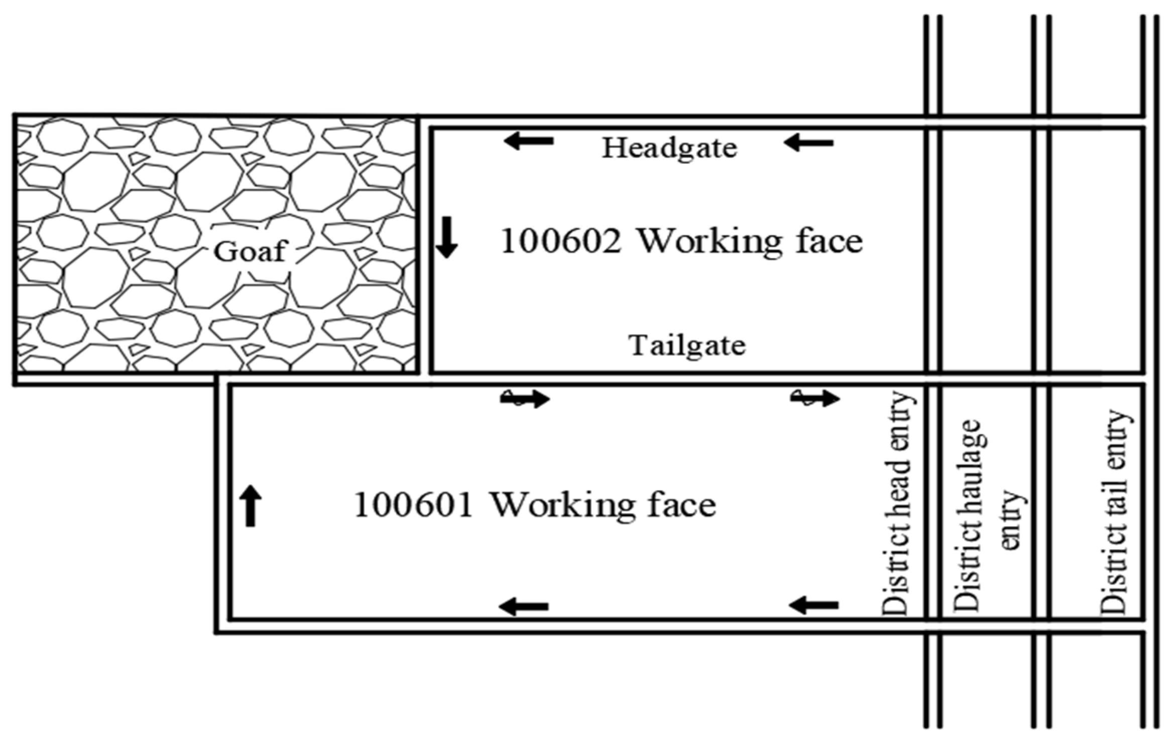
The sixth mining area of Yitang coal mine has an east–west strike length of 1340 m, a north–south dip length of 1400 m, and a mining elevation of +175 m~+335 m. The geological and structural conditions of the working face are simple, the dip angle of the coal seam is 2~5°, the average coal thickness is 7.6 m, the return roadway height is 4 m, and the width is 6 m; the lithology of the roof and floor is shown in Figure 1. The open-off cut length is 150 m and the retain roadway length is 750 m; the roadway layout is shown in Figure 2. The current mining method of Yitang coal mine is slicing mining, with a top coal thickness of 1.2 m, a bottom coal thickness of 2.4 m, and an average mining height of the working face of 5.0 m. After mining, the mining height is large, the mine pressure is strong, the top coal is soft and broken, there is serious floor heave, and it is difficult to control the end face. In order to solve the above problems, it was decided that an engineering test would be carried out on the top coal gob-side entry retaining for the tailgate of the 100602 working face.

2.2. Gob-Side Entry Retaining Technology

The process of gob-side entry retaining is summarized as four steps; the process flow is shown in Figure 3.
(1)
Within 80 m of the advance working face, the designed roof support parameters are used to make up the constant resistance large deformation anchor cable and reinforcement anchor cable to reinforce the roof and improve its pressure-bearing capacity, so as to lay the foundation for resisting the stress disturbance in the process of advance presplitting blasting and coal mining. The anchor cable should be long enough to reach the solid rock layer and produce a stable anchoring effect.
(2)
Within 60 m of the advance working face, the equipment is used to set up the presplitting drill holes on the roof according to the design angle, ensuring that all holes are in the same plane during the drilling process. Then, the explosives are placed in the cavity pipe and into the drill holes, and are finally detonated and form joint-cutting. The roof of the goaf side is more likely to collapse under the influence of mining pressure after slitting while cutting off the stress transmission path and weakening the stress of the roadway surrounding rock.
(3)
During mining, retractable U-shaped steel and metal mesh for gangue support are settled up within 6 meters behind the working face, so that the gangue fills the goaf and form a wall with a certain strength. In addition, a hydraulic pillar with a π beam is set up to strengthen the roof support, inhibit the roof on the side of the goaf sinking, reduce the bending moment on the roof, and enhance the stability of the roadway.
(4)
Under the support of the blocking gangue structure, the collapsed gangue in the goaf is gradually compacted, the main roof subsidence is contained, and the intense quarry stress caused by it is weakened. The surrounding rock of the lagging working face enters the stable state; then, some temporary support equipment is withdrawn and concrete is sprayed on the gangue wall surface to prevent ventilation leakage in the goaf, and the final gob-side entry retaining is complete.

2.3. Roof-Cutting Technology

(1)
Shaped charge technology
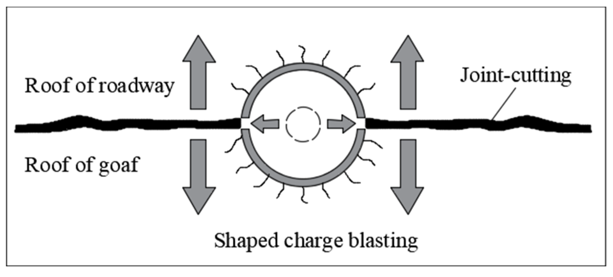
This blasting technology is a new type of concentrated energy blasting technology developed on the basis of the comparative study of many kinds of concentrated energy blasting and directional blasting methods. The construction process is simple: the application only requires the construction of gun holes in the pre-fracture line and the use of a two-way concentrated energy device charge, and the direction of the concentrated energy corresponds to the pre-fracture direction of the rock body. The blast product will form a concentrated energy flow in both set directions and generate concentrated tension stresses, causing the blast hole to penetrate along the concentrated energy direction and form a pre-cracked surface. Since the rock between the holes is fractured, the unit consumption of the blasting explosives will be greatly reduced, and at the same time, the damage to the rock around the holes will be greatly reduced due to the protection of the surrounding rock by the shaped charge device, which can achieve presplitting and protect the roof of the roadway at the same time. The principle diagram of the shaped charge is shown in Figure 4.
This study considers the geological conditions of the 100602 working face, applying actual engineering expertise to derive the parameters for pre-splitting joints on the roof of the roadway along the trough:
(1)
After reinforcing with the anchor cable, a two-way energy-concentrating tensile blasting hole is constructed 60 m ahead of the working face using design parameters. This forms a roof-cutting and pressure-relief presplit cut suture over a 30 m range.
(2)
The two-way energy-gathering tube, constructed from special energy-gathering PVC, measures 42 mm in outer diameter, 36 mm in inner diameter, and 1500 mm in length. A detonator is placed in each blast hole, charged forwards, and connected in series. Blast holes are initially designed to be 10 m deep, with the final depth determined on-site.
(3)
Concentrated energy blasting employs grade 3 emulsion explosives, using 2~4 rolls of 32 mm × 300 mm powder per tube. The sealing hole length is at least 2.5 m, using bentonite gun mud for sealing.
(4)
Considering on-site construction convenience, the distance between the drilling rigs is 3.8 m, and between the blast holes is 760 mm (500 mm if the hole depth is less than 8 m).
(5)
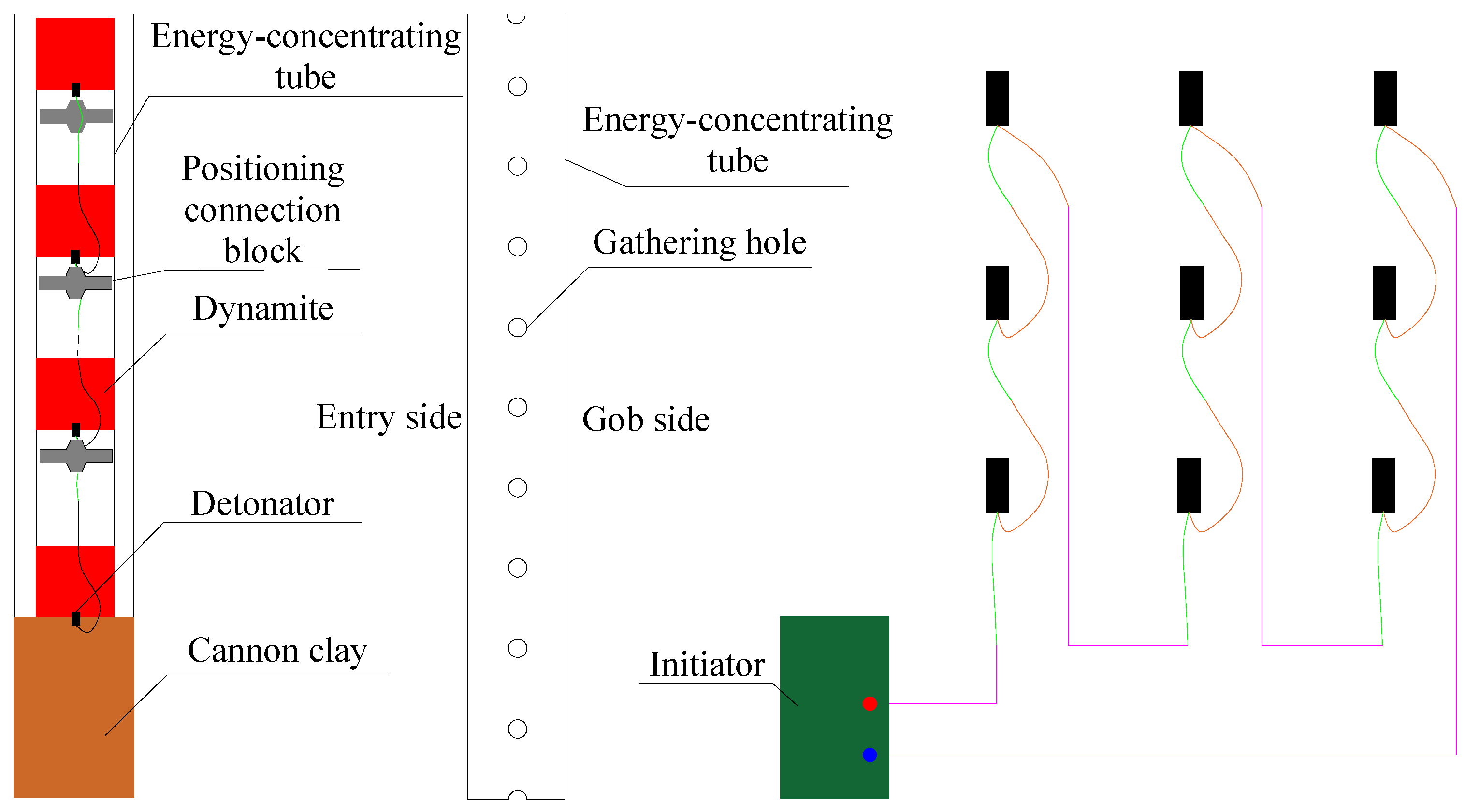
Accurate directional presplitting blasting on the roof employs energy-concentrating tube uncoupling and charging, tested using five methods. The charging structure is 4 + 4 + 4 + 2 + 2, with a mud-sealing depth of 2500 mm.
(6)
Before mining, energy-focused blasting kerfs are implemented on the gob-side roof, as shown in Figure 5.
(2)
Parameter design
The vertical distance from the top of the roadway to the farthest end of the cut line is the roof-cutting height. The collapsed form of the rock, the strength of the roadway by the mining impact, and whether the gangue can fill the goaf depend on the roof-cutting height. Based on the theory of rock fragmentation and expansion, taking into account the amount of roof subsidence, the amount of floor heaving, and the characteristics of the top coal gob-side entry retaining, the formula for calculating the roof-cutting height is as follows:
H q = H c + H f H 1 H 2 K 1
where H q is the roof-cutting height, m; H c is the coal seam mining height, m; H f is the thickness of the top coal, m; H 1 is the roof subsidence, m; H 2 is the floor heaving, m; and K is the coefficient of rock fragmentation and expansion, generally taken as 1.3~1.5.
The borehole dip angle is an important process parameter that affects the effect of gob-side entry retaining. If the cutting angle is too large, the difficulty of the construction increases and the load on the cantilever beam itself increases. If the cutting angle is too small, it will cause the roof on the goaf side to compress and damage the gob-side entry roof during the falling process, causing the roof strata of the goaf to not collapse along the joint-cutting. When designing the cutting angle, we need to fully consider the rock engineering environment and the influence of mining activities, which, according to the engineering conditions, can be calculated using the following formula:
α = 1 2 a r c sin 3 r H q 2 [ σ t ] ( K 1 )
where H q is the roof-cutting height, m; σ t is the tensile strength of the roof, MPa; α is the borehole dip angle between the joint-cutting and the vertical direction, °; and K is the coefficient of rock fragmentation and expansion, generally taken as 1.3~1.5. Engineering experience shows that the borehole dip angle should not be greater than 20°.
In order to form interpenetrated cracks between two boreholes so that the roof of the gob-side entry eventually forms presplitting joint-cutting along the set direction, it is necessary to select suitable borehole spacing. Based on cohesive explosive C-J theory and combined with the conservation of momentum theorem and rock blasting damage theory, the range of rock damage caused by the detonation wave generated by the explosion of the explosives in the borehole on both sides can be expressed as:
R = r 0 K s T m 1 D 0 σ 0 + P 1 c
where r 0 is the radius of the borehole, mm; D 0 is the initial damage to the roof rock; σ 0 is the tensile strength of the roof, MPa; P is the original rock stress, MPa; c is the explosive blasting decay index, c = 2 μ 1 μ ; T m is the maximum shockwave pressure of the borehole wall, MPa; and K s is the side pressure coefficient.
After the explosive blasting in the borehole, the rock damage area disturbed by the blasting impact should form a superimposed area between the two boreholes. The borehole spacing d should be less than or equal to 2R in order to achieve a better presplitting effect.

3. Numerical Simulation Analysis

3.1. Model Establishment and Simulation Scheme

Combined with the engineering geological conditions of Yitang coal mine, a numerical calculation model with a width of 240 m and a height of 60 m was established using PFC2D 5.0 numerical simulation software. Taking into account the influence of the boundary, the lower left and right ends of the model were set as fixed boundaries, and a vertical stress of 6 MPa was applied to the upper boundary to equate the overburden load. The length of the working face was 150 m, the width of the roadway was 6 m, and the height was 4 m. The numerical simulation process is as follows: the original model is balanced, the roadway is excavated and the roof cut, the face is mined gradually, and the roadway deformation law is analyzed after the collapse of the goaf is complete. The numerical model is shown in Figure 6. The physical and mechanical parameters of coal and rock are shown in Table 1.
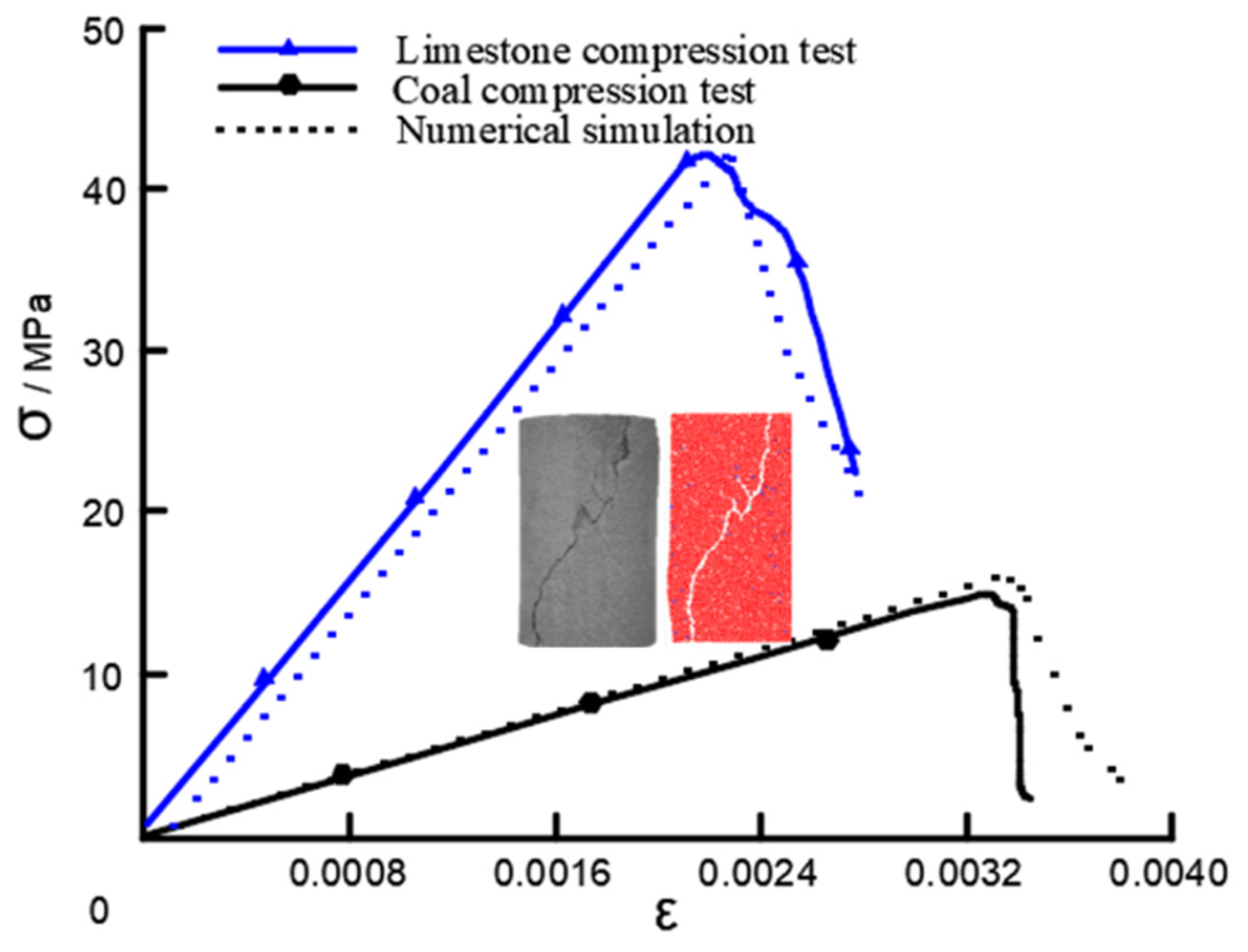
PFC2D is a discrete element numerical simulation software package. In order to ensure the simulation results are true and reliable, it is necessary to calibrate the microscopic parameters and bind the simulation parameters with the parameters of real rock mechanics. Based on the on-site retrieval of rock cores and the completion of indoor mechanical tests, the mechanical parameters of each rock layer were obtained. Based on this, the coal and rock were calibrated. The parameter verification stress–strain curve is shown in Figure 7, and the microscopic parameters of the verified model are shown in Table 2.
According to the technical characteristics of top coal gob-side entry retaining and the engineering mining conditions, four factors were selected: roof-cutting height, borehole dip angle, mining height, and coal seam thickness. Three levels were set for each factor to investigate their influence on the effect of top coal gob-side entry retaining, and a total of 12 groups of numerical simulation schemes were designed according to the principle of the single variable, as shown in Table 3.

3.2. Analysis of Displacement Field of Surrounding Rock

From Figure 8a–c, it can be seen that the roof subsidence displacement is 142 cm, 62 cm, and 106 cm under different top cutting heights. When the roof-cutting height is 12 m, the cutting seam only partially cuts off the limestone roof. The extrusion pressure generated by the main roof bending and sinking is transferred from the rock roof to the roadway, the coal beam is fractured, and the coal seam roof is completely dislodged. When the roof-cutting height is 16 m, the joint-cutting completely cuts off the limestone roof, the main roof bending and sinking process has less influence on the cantilever beam, the integrity of the coal seam roof is better, and the roof subsidence is more moderate. When the roof-cutting height is 20 m, the joint-cutting completely cuts off the mudstone layer below the main roof, the main roof subsidence space becomes larger, the cantilever beam structure self-weight increases, and the displacement of the roof on the joint-cutting side increases obviously.
From Figure 8d–f, it can be seen that the roof subsidence displacement is 44 cm, 62 cm, and 122 cm under different borehole dip angles. When the borehole dip angle is 0°, the collapse of the rock in the goaf will be obstructed by the rock on the other side of the joint-cutting, which means the collapse of the goaf is not complete under the same calculation conditions. The bending and sinking of the main roof is smaller, and the roof subsidence displacement is also smaller. When the borehole dip angle is 10°, the collapse of the rock layer in the goaf is not obstructed by the rock body on the other side of joint-cutting. The collapse of each rock layer is complete, the structure of the cantilever beam is intact, and the roof subsidence displacement increases slowly. When the borehole dip angle is 20°, the cantilever beam structure volume becomes bigger and the weight of the cantilever beam itself increases because the angle is too inclined. Under the extrusion of main roof deformation, the roof near to the buttock structural body is torn, the cantilever beam structure as a whole is destabilized, and the roadway produces large deformations.
From Figure 8g–i, it can be seen that under different mining heights, the roof subsidence displacement is 59 cm, 62 cm, and 66 cm, respectively. After the roof is cut off, the influence of mining height on the surrounding rock of the roadway is greatly weakened, and with the increase in the mining height, the roof subsidence displacement only increases a little; however, the impact of the collapsed rock on the gangue-retaining structure obviously increases, and the gap between the main roof and the cut-off rock layer will also increase. The coal seam roof and cantilever beam structure under each mining height are in a stable state, and considering that the height difference between the crossheading and the working face will increase the difficulty of the end support, consistency should be maintained between the two as much as possible when mining.
From Figure 8j–l, it can be seen that the roof subsidence displacement is 106 cm, 62 cm, and 96 cm, respectively, under different coal seam thicknesses. When the thickness of the coal seam is 6 m, the top coal is thin and the shear resistance is weak, so it breaks at the shoulder corner of the roadway under the influence of mining and the whole coal seam roof falls. When the thickness of the coal seam is 8 m, the top coal thickness increases and the shear resistance is stronger. The roof of the coal seam and the roof of the rock seam are not separated from each other, and the deformation of the compound roof follows the same trend. When the thickness of the coal seam is 10 m, the increase in the coal thickness means that the roof-cutting height can only reach the upper part of the limestone roof, which cannot be completely cut off. The percentage of fragile coal body in the cantilever beam structure increases and the percentage of hard rock body decreases, so that its bearing capacity decreases greatly, and, finally, vertical tearing occurs on the side of the cantilever beam near the buttock, and the whole structure collapses downward.
The comprehensive analysis of the above indicates that the roof-cutting height calculations should try to ensure that the immediate roof or main roof can be completely cut off. It is not meaningful to increase the roof-cutting height; under the premise of ensuring that the collapse of the cut rock is not hindered, the borehole dip angle should be reduced to improve the stability of the cantilever beam structure; when the thickness of the coal seam roof is thin, it delamination should be prevented, and when the thickness of the coal seam roof is thick, the effect of roof cutting is poor. After the increase in the mining height, the gangue-retaining structure should be strengthened. The process parameters of Yitang top coal gob-side entry retaining are determined as follows: roof-cutting height, 16 m; borehole dip angle, 10°; mining height, 4 m; coal seam thickness, 8 m. In addition, the roof subsidence displacement is larger in the simulation results, which is because no support structure such as anchors and cables are applied in the simulation, and the roof subsidence displacement is expected to be smaller under a reasonable support system when field tests are conducted.

3.3. Analysis of Stress Field in Surrounding Rock

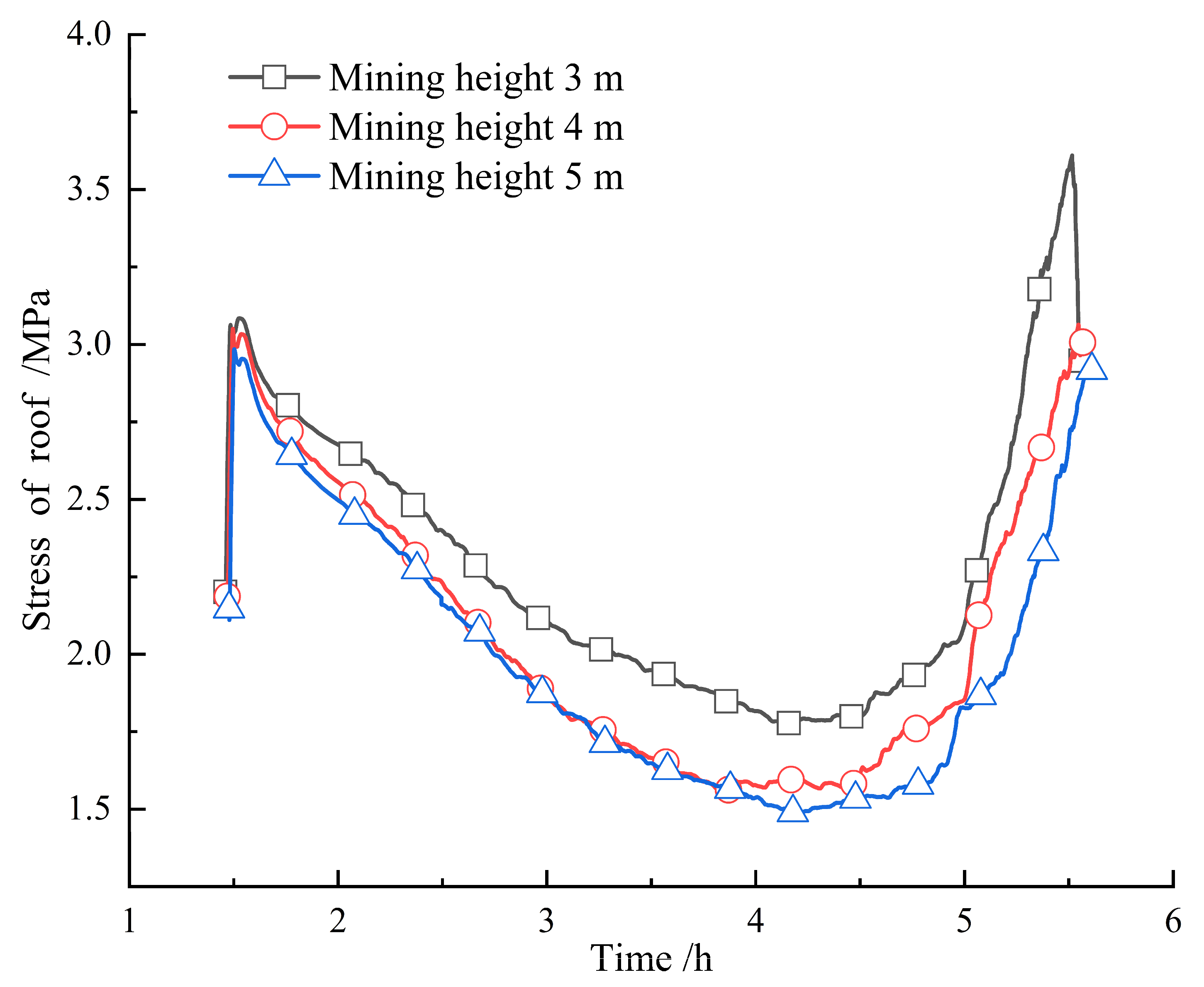
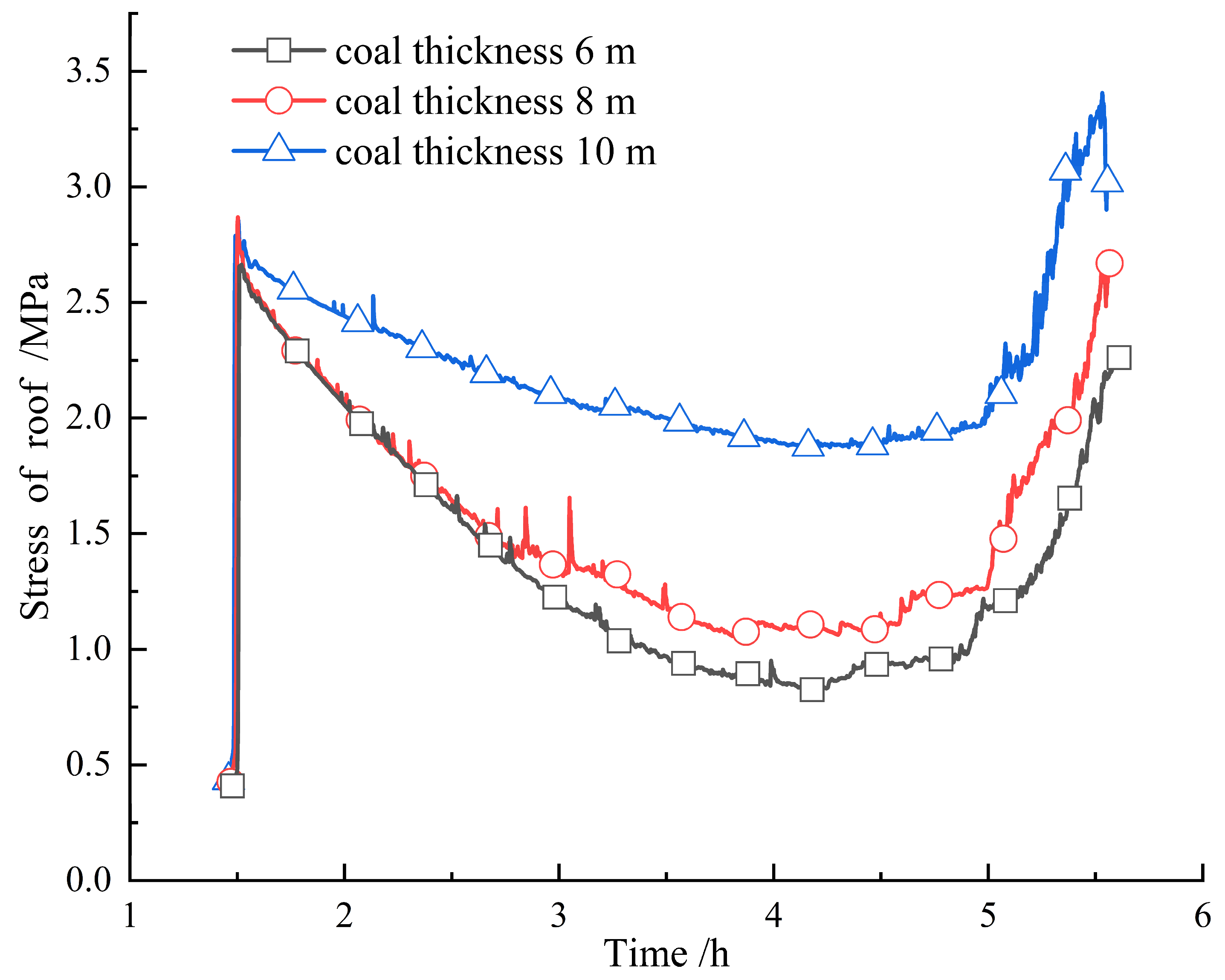
From the analysis of Figure 9, Figure 10, Figure 11 and Figure 12, it can be seen that the variation pattern of roof stress under different factors is basically the same. After cutting the roof, the roof structure changes, and the stress rapidly increases. The early mining face is far from the roadway, and the overburden load and mining stress are borne by the gravel in the distant goaf. During the process of gradually stabilizing the surrounding rock structure, the roof stress decreases, and the overburden load on the roadway decreases with the increase in mining progress. When the mining face approaches the roadway, it is included in the mining affected area; the stress it is subjected to rapidly increases, and after collapsing and stabilizing, the stress rapidly decreases.
Under different roof-cutting heights, the peak stress of roof is 3.87 MPa, 3.27 MPa, and 2.63 MPa, respectively. As the roof-cutting height increases, the stress on the roof gradually decreases. Under different borehole dip angles, the peak stress on the roof is 2.88 MPa, 3.27 MPa, and 3.51 MPa, respectively. As the borehole dip angle increases, the stress on the roof gradually increases. Under different mining heights, the peak stress values of the roof are 3.63 MPa, 3.27 MPa, and 2.85 MPa, respectively. As the mining height increases, the stress on the roof gradually decreases. Under different coal seam thicknesses, the peak stress values of the roof are 2.26 MPa, 3.27 MPa, and 3.47 MPa, respectively. As the coal seam thickness increases, the stress on the roof gradually increases.

4. Top Coal Roadway Support Strategy and Stay Roadway Effect

4.1. Roadway Damage Form and Mechanical Model Analysis

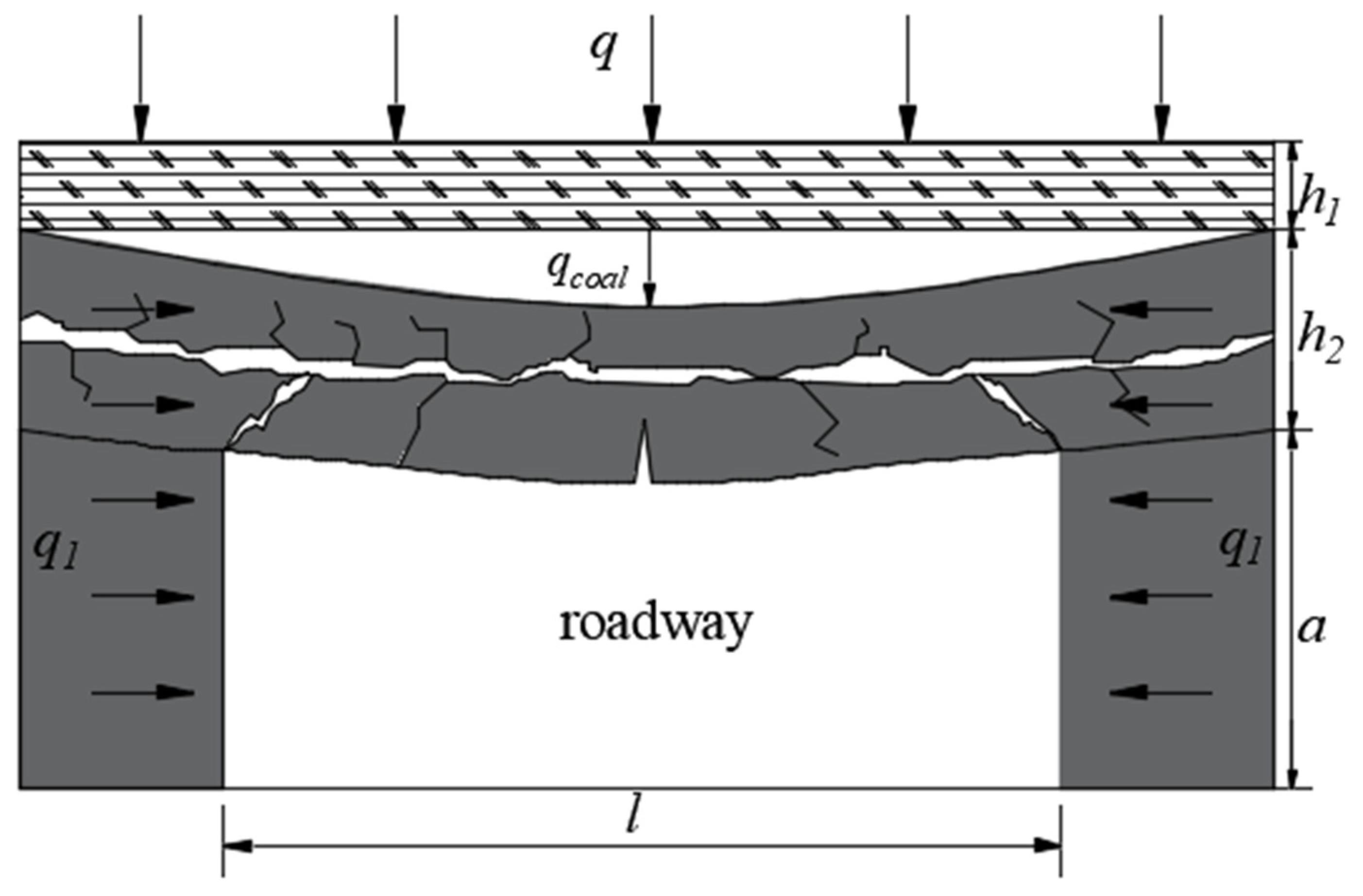
The rock structure of a traditional top coal roadway can be regarded as a coal–rock composite roof. The roof of the coal seam is soft and fragile, while the roof of the rock seam is hard. The weak roof of the coal seam bends and sinks under the action of stress; the gap between the coal seam and the rock seam is generated and further developed into delamination, and the shoulder corner of the roadway and the middle of the coal beam first reach the limit of tensile–shear damage and damage occurs. Under the stress, the bending moment of the coal beam increases while the weak surface inside the coal seam slips, and the cracks between adjacent weak surfaces penetrate each other to cut the coal beam into several parts laterally. The roof of the coal beam is severely broken, and its mechanical structure model is shown in Figure 13.
Based on the equivalent buttock-type solid support beam structure, it can be seen that the bending moment of the structure is mainly the effect of horizontal stress. The vertical stress has a small effect on the bending moment. Ignoring the effect of vertical stress, the mechanical formula can be calculated to produce the bending distance of the structure:
M = q 1 a 2 12
where q 1 is the horizontal direction uniform load, kN/m; and a is the height of the roadway, m.
After the separation of the coal roof and the rock roof, the two can be regarded as two independent beam structures. At this time, the vertical stress can be ignored, and the horizontal stress is the main cause of the coal beam damage. Using the mechanical formula, the maximum tensile stress inside the single-layer beam structure can be found:
σ m a x = 6 M b h 2 σ x
where σ m a x is the maximum tensile stress inside the beam structure, MPa; σ x is the horizontal structural stress of the beam structure, MPa; h is the thickness of the beam structure, m; b is the cross-sectional width of the beam structure, m; and M is the maximum bending moment to which the beam structure is subjected, kN·m.
Substituting Equation (4) into Equation (5), when b = 1, the maximum tensile stress inside the roof of coal beam can be obtained:
σ c o a l m a x = 3 q c o a l l 2 q 1 a 2 2 h 2 2 σ x
where q c o a l is the self-weight of the coal beam and overburden load transferred to the coal beam, MPa; and σ x is the horizontal structural stress of the beam structure, MPa.
After the roof is cut off, the mining stress transmission path is cut off, the surrounding rock structure is changed, the horizontal stress effect is weakened, and the vertical stress effect on the roof is enhanced. As can be seen from Figure 14, the bending moment of the composite roof under stress gradually increases, and the internal tensile stress of the roof accumulates. Damage occurs first at the corner of the roadway, and gradually develops into a large area of roof collapse. In this state, the coal–rock composite roof is sinking jointly, and the coal–rock composite roof can be regarded as a stacked beam. The maximum tensile stress inside this structure is:
σ m a x = 6 M b k 1 2 σ x
where k 1 is the moment of inertia discount factor of the laminated beam, which is 0.75.
The material mechanics stacked beam equation is:
M = q l 2 24 I = b h 2 12 ρ = E I M
where M is the maximum bending moment of the laminated beam structure, kN m; q is the upper load of the laminated beam structure, kN/m; l is the span of the laminated beam structure, m; I is the moment of inertia of the laminated beam structure; b is the cross-sectional width of the laminated beam structure, taken as 1 m; h is the thickness of the laminated beam structure, m; ρ is the radius of curvature of the laminated beam structure, m; and E is the modulus of elasticity of the laminated beam structure, MPa.
If the coal beam of the roof is affected by vertical tectonic stress, which is M1, the bending moment of the rock beam is M4, and the bending moment of the coal beam due to the influence of the buttock is M2, the superposition moment M3 of the coal beam by the buttock and vertical stress is M1 − M2, and the sum of the bending moment M of the coal beam and rock beam under the action of vertical tectonic stress is M1 + M4. The maximum tensile stress that the coal rock beam undergoes when the supporting top coal roadway undergoes coordinated subsidence of the coal–rock beam is:
σ c o a l m a x = E 1 h 1 ( q l 2 2 q 1 a 2 ) 4 k 1 ( E 1 h 1 3 + E 2 h 1 3 ) σ x
Since the bottom of the composite roof is the coal body, the stability of the coal beam determines the stability of the whole roadway. When the maximum tensile stress σ c o a l m a x inside the coal beam is greater than the ultimate tensile strength σ c o a l of the coal beam, the coal beam will be damaged and the whole structure will be destabilized.

4.2. Roadway Support Strategy

Based on the above discussion, it can be seen that the main control factor for the destabilization of the roadway when the coal seam roof is damaged in the process of top coal gob-side entry retaining needs to focus on the support, and its support strategy is as follows: increase the density and preload of the anchor cable to prevent the coal beam from leaving the layer and the weak surface from slipping; increase the length of the anchor cable to anchor into the deep stable rock layer, and suspend the top coal or rock beam that cannot be self-stabilized below to control its deformation; increase the density of the anchor cable to enhance the strength of the anchor beam; increase the length of the anchor cable to form a ladder-bearing structure together with the longer reinforcement anchor cable and the slightly shorter common anchor cable to give full play to the self-supporting capacity of the surrounding rock. It is also possible to consider laying metal mesh and erecting a metal beam to form a joint support structure to provide a synergistic support effect; surface spraying and shallow grouting can also be applied to the coal seam roof to improve its overall structural strength. In addition, additional single support equipment is required for mining disturbance and periodic pressure in order to maintain the stability of the roadway.
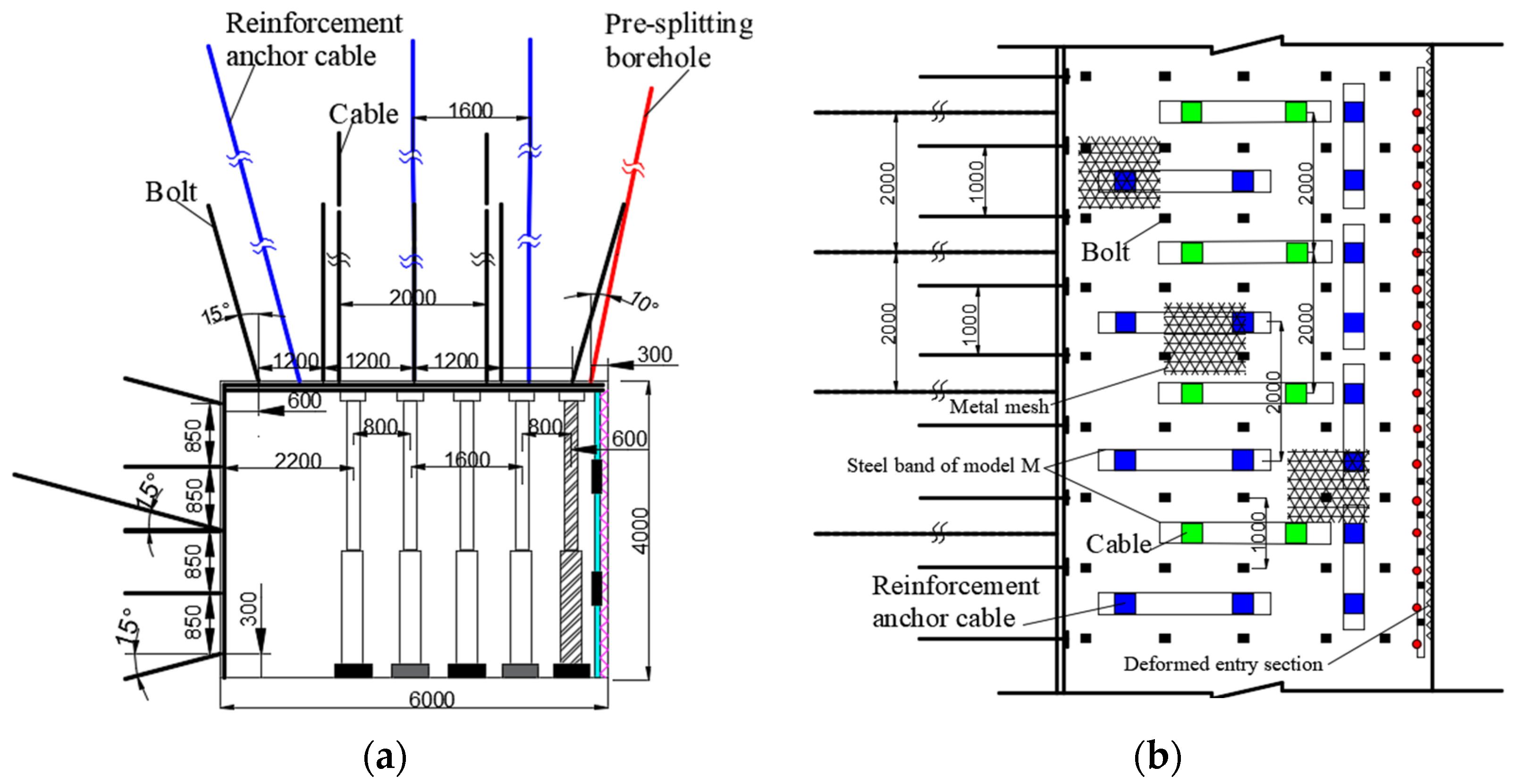
Detailed support parameters are shown in Figure 15, and the support scheme is as follows.
For roof support, the roof of the roadway is protected by an anchor mesh cable and M steel belt, with anchor rods of the size ϕ 18 mm × 4000 mm and an inter-row distance of 1200 mm × 1000 mm. The edge anchor rods are arranged at an inclination of 15°, and the rest of the anchor rods are arranged perpendicular to the roof. The anchor ropes are ϕ 21.6 mm × 10000 mm with inter-row spacing of 2000 mm × 2000 mm, and the reinforcement anchor ropes are ϕ 21.6 mm × 18,000 mm with a spacing of 1.6 m, with a row spacing of 1 m on the near-cut side and 2 m on the remaining two rows.
The anchor ropes are ϕ 18 mm × 2400 mm with an inter-row spacing of 850 mm × 1000 mm. The edge anchor ropes are arranged at 15° deviation, and the rest of the anchor ropes are arranged perpendicular to the roadway gang. The anchor ropes are ϕ 17.8 mm × 4000 mm, with a row spacing of 2 m, and are arranged at 15° from the horizontal.
For the temporary reinforcement of support, a π beam with a mono-hydraulic pillar form a “one beam and five columns” support structure. After the impact of mining, two mono-columns can be withdrawn so that it is transformed into a “one beam and three columns” form. After the roadway is stabilized, only the monolithic pillar on the side of the mining area is retained.
The gob-side entry retaining support is a combination of steel mesh, individual pillars, and expandable U-shaped steel used for gangue-retaining support within 6 m of the lagging working face. Scalable U-shaped steel with a row spacing of 600 mm and a steel mesh size of 2500 mm × 4000 mm, with an overlap of 100 mm at the joint of the steel mesh and tied with iron wire for fixation is used. If there is serious leakage on site, the steel mesh or iron wire mesh can be laid in multiple layers to strengthen the support of the blocking gangue.

4.3. Effect of the Retention Lane

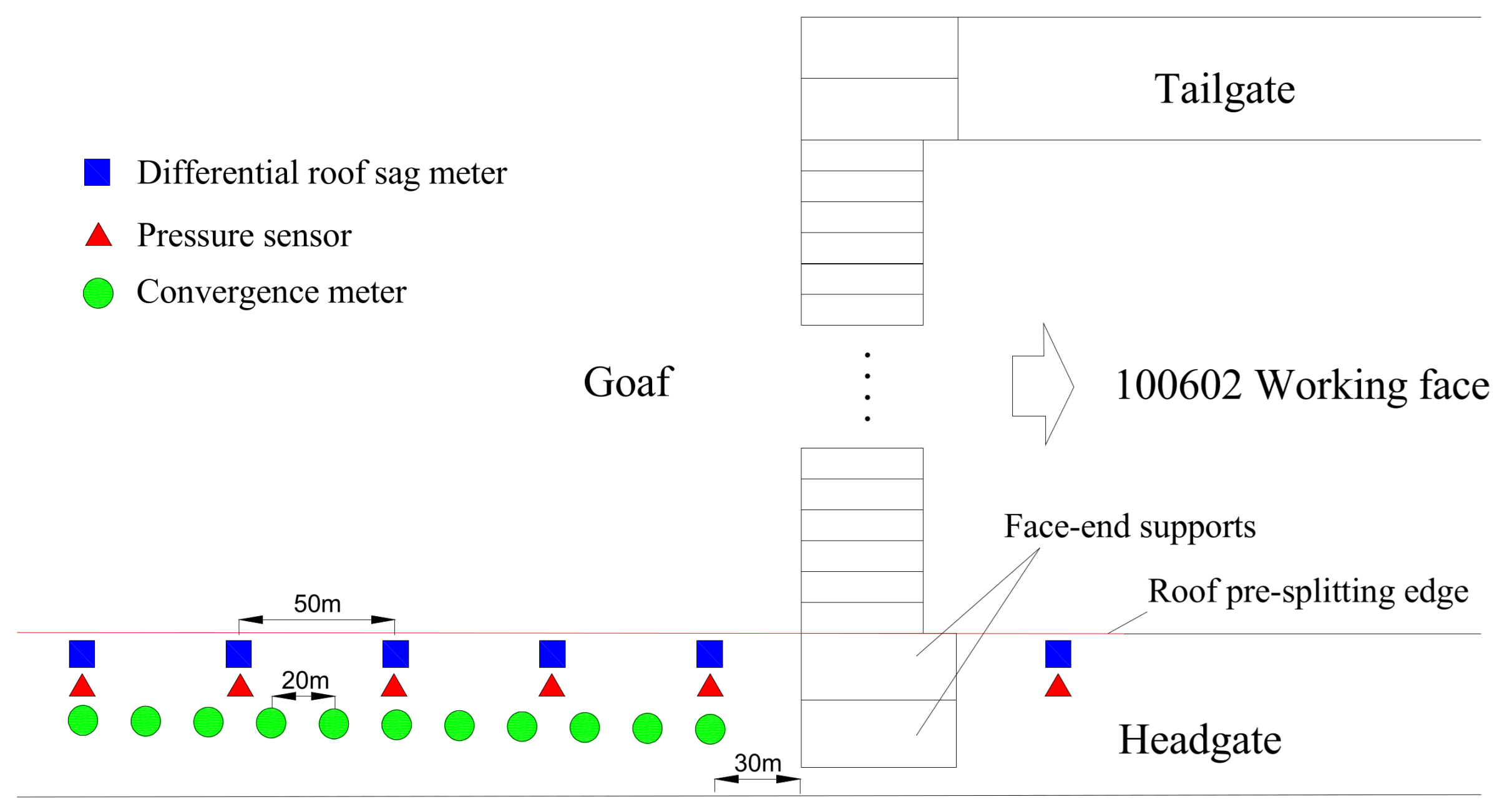
The purpose of mine pressure observation is to grasp the spatiotemporal distribution patterns of deformation and stress in the surrounding rock of the roadway by analyzing the data collected during mining, providing a scientific basis for the subsequent design of gob-side entry retaining and roadway support and ensuring safe construction. During the process of gob-side entry retaining, monitoring points should be set up to monitor the subsidence displacement of the roof, the separation of the roof layer, and the force and deformation of the anchor rod and cable. A roof separation meter and anchor rod and cable dynamometer should be installed 30 m ahead of the working face, and the first roof separation meter, roof and floor displacement sensor, and anchor rod and cable dynamometer should be installed at a distance of 30 m behind the working face. Five sets of roof separators and anchor cable force gauges are arranged at intervals of 50 m, while one set of roof and floor displacement sensors is arranged at intervals of 20 m for a total of 11 sets, all distributed within 200 m of the lagging working face. As the working face continues to advance, measurement stations within the monitoring distance of the front and rear are also added. Any measurement equipment damaged during the advancing process of the working face should be replaced and supplemented in a timely manner. The specific layout of the measurement points is shown in Figure 16.
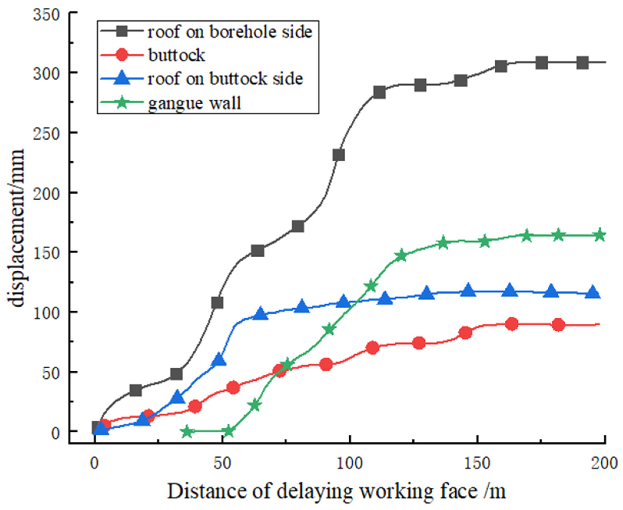
By comparing the data obtained from various measurement stations, it can be found that as the working face continues to advance, the rock pressure patterns reflected by each measurement point are basically the same. Therefore, only some typical data in the deformation of the roof and roadway sides are selected for analysis. The monitoring results are shown in Figure 17.
From the site monitoring results shown in Figure 17, the roof subsidence displacement near the joint-cutting side is larger than near the buttock side. The roof subsidence displacement near the joint-cutting side is about 308 mm, while the final roof subsidence displacement near the buttock side is about 196 mm. The final gangue wall convergence is about 164 mm, while the buttock convergence is about 116 mm. The roof subsidence is affected by the incoming pressure, showing a periodic rapid growth, while the buttock convergence is slower. Finally, at about 140 m lagging the working face, the surrounding rock of the roadway entered a stable state.
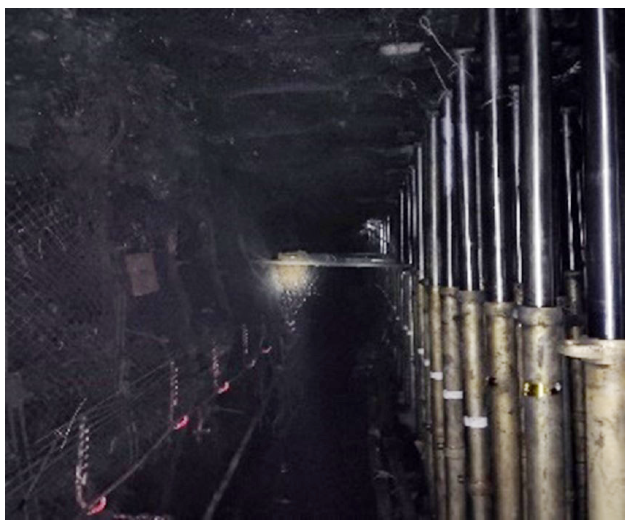
After gob-side entry retaining, the surrounding rock control effect is good. The ventilation system of the working face is improved, the speed of mining is improved, a large number of coal pillars are recovered, and good technical and economic benefits are achieved. The effect of gob-side entry retaining is shown in Figure 18.

5. Discussion

This research significantly contributes to the understanding of gob-side entry maintenance using roof-cutting techniques in fully mechanized longwall mining. By investigating the key parameters of roof pre-fracturing boreholes, we identified the optimal settings that enhance the stability of gob-side entries in ultra-thick coal seams. Moreover, field measurements verified the efficacy of these settings and the benefits of appropriate anchor-net support in forming a stable rock structure.
Nonetheless, our study has certain limitations. It focused on a specific engineering background, which might not represent all mining conditions. Therefore, the universality of our findings could be a subject for future research. Moreover, other potentially impactful factors, such as geological conditions and mining techniques, were not deeply examined. It is also important to consider alternative methods, particularly hydraulic fracturing, which involves opening the reservoir with vertical or inclined wells, placing hydraulic sandblasting perforators at given formation intervals, and pumping the working fluid into the hydraulic perforator. The nozzles of the blaster create grooves (cavities) in the formation and then fracture the formation through the gaps (cavities) that form.
Moving forward, we recommend conducting comprehensive research considering various mining conditions and additional impacting factors. This could broaden the applicability of our findings and contribute more effectively to the sustainable development of coal mines.

6. Conclusions

(1)
Based on the geological conditions of the Yitang coal mine, numerical simulation analysis was conducted on top coal gob-side entry retaining, and the influence of various factors on the effectiveness of gob-side entry retaining was explored. The simulation results indicate that under the conditions of a roof-cutting height of 16 m, borehole dip angle of 10°, mining height of 4 m, and an average thickness of 8 m in the coal seam, the roof of the coal seam did not detach and the bending settlement was small. The cantilever beam has good load-bearing capacity, and the overall structure is stable. The rock strata in the goaf collapse completely and the filling condition is good.
(2)
During the process of gob-side entry retaining, it was found that the variation pattern of the roof stress under different factors is basically the same, with a peak stress of around 3 MPa. As the roof-cutting height and mining height increase, the stress on the roof gradually decreases; as the borehole dip angle and coal seam thickness increase, the stress on the roof gradually increases.
(3)
The mechanical analysis found that the strength of the roof coal beam directly affects the stability of the roadway, and the roof stability is related to the changeable factors such as the thickness of the top coal, the span of the roadway, and the elastic modulus of the coal seam. When increasing the thickness of the top coal appropriately, the elastic modulus of the roof anchorage area is enhanced by using step support, and the span distance is reduced by using reduced span support to enhance the strength of the roof of the coal seam and maintain the stability of the surrounding rock.
(4)
The on-site monitoring data of the mine pressure shows that under a reasonable support plan, the maximum subsidence of the roof is 308 mm, and the total convergence of the roadway movement is 280 mm. The total affected area is within 140 m of the lagging working face, and the deformation of surrounding rock is well controlled, achieving certain technical and economic benefits.

Author Contributions

Project administration, Funding acquisition, Supervision, Y.Y.; Data curation, Formal analysis, Investigation, P.G.; Formal analysis, Writing—original draft, C.Z.; Methodology, Writing—review & editing, Funding acquisition, C.W. All authors have read and agreed to the published version of the manuscript.

Funding

This work was supported by the National Natural Science Foundation of China (Grant No. 51404167); Natural Science Foundation of Shanxi Province (Grant No. 201901D211066); Scientific Research Grant Project for Returned Overseas Students in Shanxi Province (HGKY2019038); Teaching Reform Innovation Project for Higher Education Institutions in Shanxi Province (J2019055); China Postdoctoral Science Foundation funding project (Grant No. 2016M590151).

Data Availability Statement

The data used to support the findings of this study are included within the article.

Conflicts of Interest

The authors declare no conflict of interest.

Nomenclature

H q the roof-cutting height, m
H c the mining height, m
H f the thickness of the top coal, m
Δ H 1 the roof subsidence displacement, m
Δ H 2 the floor heaving displacement, m
K the coefficient of rock fragmentation and expansion
σ t the tensile strength of the coal seam roof, MPa
α the borehole dip angle, °
r 0 the radius of the borehole, mm
D 0 the initial damage to the roof rock
σ 0 the tensile strength of the roof rock, MPa
P the original rock stress, MPa
c the explosive blasting decay index
T m the maximum shockwave pressure of the borehole wall, MPa
K s the side pressure coefficient
q 1 the horizontal direction overburden load, kN/m
α the height of the roadway, m
σ m a x the maximum tensile stress inside the beam structure, MPa
σ x the horizontal structural stress of the beam structure, MPa
h the thickness of the beam structure, m
b the cross-sectional width of the beam structure, m
M the maximum bending moment to which the beam structure is subjected, kN·m
q c o a l the self-weight of coal beam and overburden load transferred to coal beam, MPa
k 1 the moment of inertia discount factor of the laminated beam
q the upper load of the laminated beam structure, kN/m
l the span of the laminated beam structure, m
I the moment of inertia of the laminated beam structure
b the cross-sectional width of the laminated beam structure, m
ρ the radius of curvature of the laminated beam structure, m
E the modulus of elasticity of the laminated beam structure, MPa

References

  1. Wang, K.; Huang, Y.; Gao, H.; Zhai, W.; Qiao, Y.; Li, J.; Ouyang, S.; Li, W. Recovery Technology of Bottom Coal in the Gob-Side Entry of Thick Coal Seam Based on Floor Heave Induced by Narrow Coal Pillar. Energies 2020, 13, 3368. [Google Scholar] [CrossRef]
  2. Lv, H.; Cheng, Z.; Liu, F. Study on the mechanism of a new fully mechanical mining method for extremely thick coal seam. Int. J. Rock Mech. Min. Sci. 2021, 142, 104788. [Google Scholar] [CrossRef]
  3. Liu, S.; Yang, K.; Tang, C.; Chi, X. Rupture and Migration Law of Disturbed Overburden during Slicing Mining of Steeply Dipping Thick Coal Seam. Adv. Civ. Eng. 2020, 2020, 8863547. [Google Scholar] [CrossRef]
  4. Liu, S.; Huang, J.; Huang, Q.; Li, T.; Tang, S.; Liu, X. Floor Pressure-Relief During Top Slice Mining of Extra-Thick Coal Seams and Its Implications for Gas Drainage Application. Geotech. Geol. Eng. 2019, 37, 3113–3125. [Google Scholar] [CrossRef]
  5. Li, Z.-L.; He, X.-Q.; Dou, L.-M.; Song, D.-Z. Comparison of rockburst occurrence during extraction of thick coal seams using top-coal caving versus slicing mining methods. Can. Geotech. J. 2018, 55, 1433–1450. [Google Scholar] [CrossRef]
  6. He, W.; He, F.; Zhao, Y. Field and simulation study of the rational coal pillar width in extra-thick coal seams. Energy Sci. Eng. 2019, 8, 627–646. [Google Scholar] [CrossRef] [Green Version]
  7. Li, X.; Zhao, Y.; He, W.; Li, L.; He, F. Study on Coal Pillar Width and Surrounding Rock Control of Gob-Side Entry in Extra-thick Coal Seam. Geotech. Geol. Eng. 2020, 38, 6855–6868. [Google Scholar] [CrossRef]
  8. Wang, Q.; Jiang, Z.; Jiang, B.; Gao, H.; Huang, Y.; Zhang, P. Research on an automatic roadway formation method in deep mining areas by roof cutting with high-strength bolt-grouting. Int. J. Rock Mech. Min. Sci. 2020, 128, 104264. [Google Scholar] [CrossRef]
  9. Çelik, A.; Özçelik, Y. Investigation of the efficiency of longwall top coal caving method applied by forming a face in horizontal thickness of the seam in steeply inclined thick coal seams by using a physical model. Int. J. Rock Mech. Min. Sci. 2021, 148, 104917. [Google Scholar] [CrossRef]
  10. Liang, Y.; Li, L.; Li, X.; Wang, K.; Chen, J.; Sun, Z.; Yang, X. Study on Roof-Coal Caving Characteristics with Complicated Structure by Fully Mechanized Caving Mining. Shock. Vib. 2019, 2019, 6519213. [Google Scholar] [CrossRef]
  11. Wang, E.; Xie, S. Determination of coal pillar width for gob-side entry driving in isolated coal face and its control in deep soft-broken coal seam: A case study. Energy Sci. Eng. 2022, 10, 2305–2316. [Google Scholar] [CrossRef]
  12. Ma, Z.; Chen, C.; Liang, X.; Chen, A.; Song, W. Field and numerical investigation on the stability of coal pillars of gob-side entry driving with top coal. Arab. J. Geosci. 2020, 13, 1193. [Google Scholar] [CrossRef]
  13. Wang, B.; Dang, F.; Gu, S.; Huang, R.; Miao, Y.; Chao, W. Method for determining the width of protective coal pillar in the pre-driven longwall recovery room considering main roof failure form. Int. J. Rock Mech. Min. Sci. 2020, 130, 104340. [Google Scholar] [CrossRef]
  14. Chen, A. Width Design of Small Coal Pillar of Gob-Side Entry Driving in Soft Rock Working Face and Its Application of Zaoquan Coal Mine. Adv. Civ. Eng. 2021, 2021, 9999957. [Google Scholar] [CrossRef]
  15. Qi, F.; Zhou, Y.; Cao, Z.; Zhang, Q.; Li,, N. Width optimization of narrow coal pillar of roadway driving along goaf in fully mechanized top coal caving face. J. Min. Saf. Eng. 2016, 33, 475. [Google Scholar]
  16. Wang, Y.; Li, Y.; Yu, Z.; Zhang, H.; Ding, D. Research on the Surrounding Rock Control Technology of Gob-Side Entry with a Narrow Coal Pillar Reserved in a Fully Mechanized Caving Face with Large Mining Height. Geotech. Geol. Eng. 2021, 40, 285–300. [Google Scholar] [CrossRef]
  17. Sakhno, I.; Sakhno, S. Numerical Studies of Floor Heave Control in Deep Mining Roadways with Soft Rocks by the Rock Bolts Reinforcement Technology. Adv. Civ. Eng. 2023, 2023, 2756105. [Google Scholar] [CrossRef]
  18. Bosikov, I.I.; Martyushev, N.V.; Klyuev, R.V.; Savchenko, I.A.; Kukartsev, V.V.; Kukartsev, V.A.; Tynchenko, Y.A. Modeling and Complex Analysis of the Topology Parameters of Ventilation Networks When Ensuring Fire Safety While Developing Coal and Gas Deposits. Fire 2023, 6, 95. [Google Scholar] [CrossRef]
  19. Balovtsev, S.; National University of Science and Technology; Skopintseva, O.; Kolikov, K. Misis Aerological risk management in preparation mining of coal mines. Sustain. Dev. Mt. Territ. 2022, 14, 107–116. [Google Scholar] [CrossRef]
  20. Tian, Z.; Zhang, Z.; Deng, M.; Yan, S.; Bai, J. Gob-Side Entry Retained with Soft Roof, Floor, and Seam in Thin Coal Seams: A Case Study. Sustainability 2020, 12, 1197. [Google Scholar] [CrossRef] [Green Version]
  21. Xie, S.; Wang, E.; Chen, D.; Li, H.; Jiang, Z.; Yang, H. Stability analysis and control technology of gob-side entry retaining with double roadways by filling with high-water material in gently inclined coal seam. Int. J. Coal Sci. Technol. 2022, 9, 52. [Google Scholar] [CrossRef]
  22. Cheng, Y.; Jiang, F.; Lin, J.; Chen, Q.; Zhang, D.; Zhang, F. Experimental Study on Gob Side Entry Retaining by Roadside Flexible Packing Under Hard Roof. J. Min. Saf. Eng. 2012, 29, 757. [Google Scholar]
  23. Zhang, Y.; Wang, X. Modification test of high-water packing material and application in the gob-side entry retained engineering. Arab. J. Geosci. 2022, 15, 579. [Google Scholar] [CrossRef]
  24. Sun, X.; Li, G.; Song, P.; Miao, C.; Zhao, C.; Li, Q.; Xia, X. Application Research on Gob-Side Entry Retaining Methods in No. 1200 Working Face in Zhongxing Mine. Geotech. Geol. Eng. 2018, 37, 185–200. [Google Scholar] [CrossRef]
  25. Zhang, X.; Chen, L.; Gao, Y.; Hu, J.; Yang, J.; He, M. Study of An Innovative Approach of Roof Presplitting for Gob-Side Entry Retaining in Longwall Coal Mining. Energies 2019, 12, 3316. [Google Scholar] [CrossRef] [Green Version]
  26. Zhao, H. State-of-the-art of standing supports for gob-side entry retaining technology in China. J. S. Afr. Inst. Min. Metall. 2019, 119, 891–906. [Google Scholar] [CrossRef]
  27. Han, C.; Yang, H.; Zhang, N.; Li, X.; Liu, Y.; Liu, W.; Yao, W. Study on Reasonable Coal Pillar Width of Gob-Side Roadway Excavating with Multi-Layer Hard Roof in Western Deep Mine. Geotech. Geol. Eng. 2021, 40, 1417–1428. [Google Scholar] [CrossRef]
  28. Zhou, X.; Li, H.; Li, X.; Wang, J.; Meng, J.; Li, M.; Mei, C. Research on Gob-Side Entry Retaining Mining of Fully Mechanized Working Face in Steeply Inclined Coal Seam: A Case in Xinqiang Coal Mine. Sustainability 2022, 14, 10330. [Google Scholar] [CrossRef]
  29. Yang, X.; Sun, Y.; Wang, E.; Mao, W. Study and Application of Gob-Side Entry Retaining Formed by Roof Cutting and Pressure Relief in Medium-Thickness Coal Seam with Hard Roof. Geotech. Geol. Eng. 2020, 38, 3709–3723. [Google Scholar] [CrossRef]
  30. Wu, H.; Li, Q.; Zhu, C.; He, L. Study on the failure law of surrounding rock in inclined coal seam with gob side entry. Sci. Rep. 2023, 13, 973. [Google Scholar] [CrossRef]
  31. Ma, X.; He, M.; Wang, J.; Gao, Y.; Zhu, D.; Liu, Y. Mine Strata Pressure Characteristics and Mechanisms in Gob-Side Entry Retention by Roof Cutting under Medium-Thick Coal Seam and Compound Roof Conditions. Energies 2018, 11, 2539. [Google Scholar] [CrossRef] [Green Version]
  32. Fu, W. Study on Surrounding Rock Control of Gob-Side Entry Retaining in Inclined and Thick Longwall Face. Geotech. Geol. Eng. 2022, 40, 3477–3491. [Google Scholar] [CrossRef]
  33. Kong, D.; Pu, S.; Cheng, Z.; Wu, G.; Liu, Y. Coordinated deformation mechanism of the top coal and filling body of gob-side entry retaining in a fully mechanized caving face. Int. J. Geomech. 2021, 21, 04021030. [Google Scholar] [CrossRef]
  34. Wang, H.; Wang, J.; He, M.; Ma, Z.; Tian, X.; Liu, P. A novel non-pillar coal mining technology in longwall top coal caving: A case study. Energy Sci. Eng. 2023, 11, 1822–1841. [Google Scholar] [CrossRef]
  35. Xie, S.; Wu, Y.; Guo, F.; Zou, H.; Chen, D.; Zhang, X.; Ma, X.; Liu, R.; Wu, C. Application of Pre-Splitting and Roof-Cutting Control Technology in Coal Mining: A Review of Technology. Energies 2022, 15, 6489. [Google Scholar] [CrossRef]
  36. Wang, Q.; He, M.; Yang, J.; Gao, H.; Jiang, B.; Yu, H. Study of a no-pillar mining technique with automatically formed gob-side entry retaining for longwall mining in coal mines. Int. J. Rock Mech. Min. Sci. 2018, 110, 1–8. [Google Scholar] [CrossRef]
  37. Ma, Z.; Wang, J.; He, M.; Gao, Y.; Hu, J. Key Technologies and Application Test of an Innovative Noncoal Pillar Mining Approach: A Case Study. Energies 2018, 11, 2853. [Google Scholar] [CrossRef] [Green Version]
  38. Zhen, E.; Wang, Y.; Yang, J.; He, M. Comparison of the macroscopical stress field distribution characteristics between a novel non-pillar mining technique and two other current methods. Adv. Mech. Eng. 2019, 11, 1687814019850418. [Google Scholar] [CrossRef]
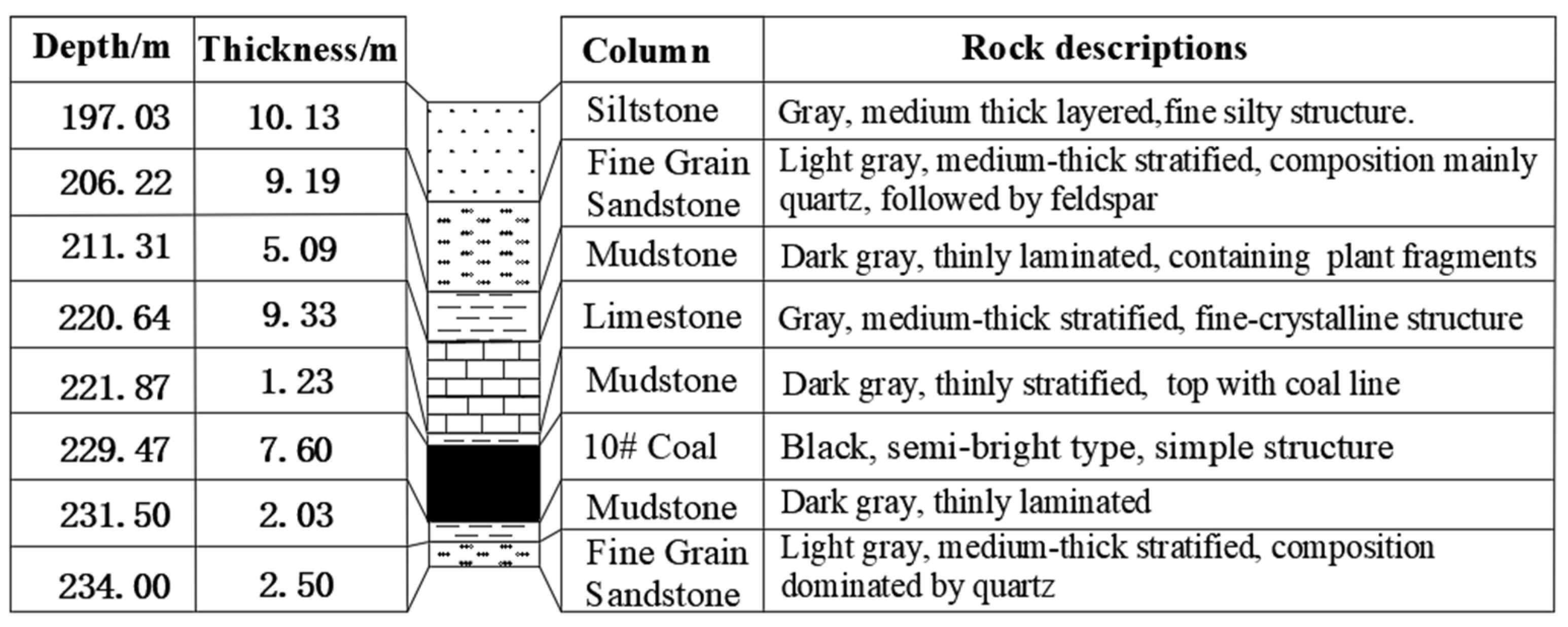
Figure 1. Integrated rock layer column diagram.
Energies 16 04788 g001
Figure 2. Roadway layout plan.
Energies 16 04788 g002
Figure 3. Process flow for gob-side entry retaining.
Energies 16 04788 g003
Figure 4. Schematic diagram of the mechanism of shaped charge blasting.
Energies 16 04788 g004
Figure 5. Schematic diagram of the mechanism of shaped charge blasting.
Energies 16 04788 g005
Figure 6. Numerical model of cut top formation.
Energies 16 04788 g006
Figure 7. Stress–strain curve for parameter verification of numerical model.
Energies 16 04788 g007
Figure 8. Comparison of roadway displacement.
Energies 16 04788 g008
Figure 9. Roof stress variation curve under different roof-cutting heights.
Energies 16 04788 g009
Figure 10. Roof stress variation curve under different borehole dip angles.
Energies 16 04788 g010
Figure 11. Roof stress variation curve under different mining heights.
Energies 16 04788 g011
Figure 12. Roof stress variation curve under different coal thicknesses.
Energies 16 04788 g012
Figure 13. Roadway damage mechanics model of the top coal.
Energies 16 04788 g013
Figure 14. Mechanical model of roof damage after roof cutting.
Energies 16 04788 g014
Figure 15. Roadway support layout diagram. (a) Cross-sectional drawing of the roadway support; (b) roadway top plate support plan.
Energies 16 04788 g015
Figure 16. Field measurement configuration.
Energies 16 04788 g016
Figure 17. Field measurement data.
Energies 16 04788 g017
Figure 18. Effect of gob-side entry retaining.
Energies 16 04788 g018
Table 1. Mechanical parameters of each rock formation.
LithologyDensity/g·cm−3Compressive Strength/MPaTensile Strength/MPaCohesion/MPaElastic Modulus/MPaPoisson’s RatioFriction Angle/°
Siltstone2.5731.582.889.3242380.3130.33
Fine sandstone2.6051.795.6513.0058360.2427.14
Mudstone2.5230.103.825.0138130.2628.20
Limestone2.5440.834.458.0230230.3634.53
Mudstone2.5334.773.784.7838650.3027.56
No. 10 coal1.4511.000.903.1011000.2828.00
Mudstone2.5334.773.784.7838650.3027.56
Fine sandstone2.6051.795.6513.0058360.2427.14
Table 2. Numerical model microscopic parameters.
LithologyPb_emod/GPaPb_kratioPb_ten/MPaPb_coh/MPaPb_fa/°
Siltstone0.471.35103020
Fine sandstone0.441.20235428
Mudstone0.501.25181430
Limestone0.491.00253622
Mudstone0.481.40141230
No. 10 coal0.282.002816
Mudstone0.481.43161332
Fine sandstone0.431.22245527
Table 3. Numerical simulation scheme for cutting the top into a lane.
Factor
Scheme Number
Height of Roof Cutting/mBorehole Dip Angle/°Mining Height/mCoal-Seam Thickness/m
1–312, 16, 201048
4–6160, 10, 2048
7–916103, 4, 58
10–12161046, 8, 10
Disclaimer/Publisher’s Note: The statements, opinions and data contained in all publications are solely those of the individual author(s) and contributor(s) and not of MDPI and/or the editor(s). MDPI and/or the editor(s) disclaim responsibility for any injury to people or property resulting from any ideas, methods, instructions or products referred to in the content.