Article

Adaptive Control of a Virtual Synchronous Generator with Multiparameter Coordination

1
State Grid Jiangsu Electric Power Company Ltd., Research Institute, Nanjing 211103, China
2
NARI School of Electrical and Automation Engineering, Nanjing Normal University, Nanjing 210023, China
*
Author to whom correspondence should be addressed.
Energies 2023, 16(12), 4789; https://doi.org/10.3390/en16124789
Submission received: 24 April 2023 / Revised: 1 June 2023 / Accepted: 5 June 2023 / Published: 19 June 2023
(This article belongs to the Special Issue Energy, Electrical and Power Engineering 2021-2022)

Abstract

:
This paper proposes an adaptive strategy of co-regulating the three parameters—P/ω droop coefficient, virtual inertia, and damping coefficient—for the virtual synchronous generator (VSG). This approach is able to solve the uncoordinated performance between the virtual inertia and the damping using the conventional adaptive control in which the system may experience serious frequency fluctuations. Through the mathematical modeling of the VSG grid-connected system, the segmental analysis of the VSG transient process is carried out, and the parameter adjustment law of each stage is obtained. The VSG angular velocity change and the angular velocity instantaneous change rate are associated with the inertia to realize the adaptive adjustment of the inertia, and the adaptive adjustment of the P/ω droop coefficient is carried out in real time according to the VSG angular velocity change. A functional relationship is established between the P/ω droop coefficient, virtual inertia, and damping coefficient so that the P/ω droop coefficient, virtual inertia, and damping coefficient are coordinated to keep the system in the best damping ratio state all the time. Finally, the superiority of the proposed strategy is proved by simulation comparison.

1. Introduction

With the increasingly serious environmental pollution and the exhaustion of traditional fossil energy, clean energy, such as wind and light, has become an indispensable alternative [1]. New energy power generation is generally connected to the AC microgrid through the inverter device, but since the inverter device does not have the inertia and damping of the synchronous generator when it is connected in a large proportion, the inertia and damping of the system will be insufficient. When disturbed, its ability to suppress interference becomes weak and even causes the system frequency to collapse in severe cases [2,3].
The virtual synchronous generator control [4] simulates the inertia and damping characteristics of the synchronous generator, while the inverter equipment can also provide inertia and damping support for the system. Virtual inertia and damping are the core control parameters of VSG, which are flexible and adjustable, and proper adjustment of these parameters can effectively improve the control performance of VSG. With the increase in the proportion of new energy connected to the power system, VSG technology has received more and more attention from researchers. Ref. [5] proposes a virtual inertial control strategy for the microgrid system with energy storage, which effectively improves the frequency characteristics of the microgrid system. However, when the proportion of new energy inside the system changes, its inertia takes a fixed value, and the frequency response characteristics of the system deteriorate. To solve this problem, adjustment techniques based on adaptive strategies have been proposed by researchers [6,7,8,9,10,11,12,13]. Ref. [8] proposed a VSG virtual inertia adaptive control algorithm based on stick control. When the rate of change of the angular frequency is less than a certain threshold, the inertia takes a smaller value; otherwise, it takes a larger value. However, stage adjustment and the optimal tracking of inertia to frequency changes cannot be achieved. Ref. [9] proposes a virtual inertia adaptive control strategy that is jointly determined by the VSG rotor angular frequency change rate and deviation, which solves the adaptive effective tracking to a certain extent, but the selection range of virtual inertia and the basis for the selection of key parameters are not given in the paper. Refs. [11,12] proposed a coordinated adaptive control strategy of inertia and damping. When the VSG angular frequency change rate increases, the inertia value is higher, and when the angular frequency deviation increases, the damping value is higher, which effectively improves the dynamic and static state of the system frequency performance; however, only the adaptive expression is given, and the selection basis of the correlation coefficient in the expression cannot be given. Ref. [13] proposed a cooperative adaptive control strategy for VSG parameters. The strategy uses an exponential adaptive algorithm to determine the virtual inertia, which reduces the sensitivity of the relevant control parameters in the adaptive algorithm and combines the performance index constraints to achieve the coordination of the damping coefficient, which realizes the optimal tracking of inertia and damping for frequency changes. However, the paper ignores the effect of the P/ω droop coefficient. The literature [14] proposes an adaptive inertial damping integrated control (SA-RIDC) method, which decides whether to adjust the virtual inertia or the damping coefficient according to the derivative of the angular frequency differential during frequency oscillations in order to achieve alternating control of the virtual inertia and the damping coefficient. The literature [15] proposes a control strategy based on a joint adaptive virtual rotational inertia and damping coefficient with an optimal damping ratio. The literature [16] proposes an adaptive VSG control strategy for battery energy storage systems to ensure the stability of the power system. The literature [17] draws on the work angle and angular frequency curves of synchronous generators to design a refined virtual inertia fuzzy regulation law, while considering the four performance indicators of active overshoot, the frequency rate of change, regulation time, and rise time to select a suitable damping ratio, and the virtual damping is coordinated and adaptively adjusted according to the selected damping ratio with the change of virtual inertia. In the paper [18], virtual synchronous generator technology was introduced in the IIDG control system to optimize the active-frequency control, the reactive-voltage control, and the voltage-current control, respectively. The impact of the damping coefficient on the output of the microgrid system is analyzed by means of a small signal model, and a self-adaptive damping control strategy is proposed.
In this paper, an improved VSG multiparameter optimal cooperative control strategy is proposed. Based on the optimal damping ratio, the initial value of the virtual inertia and the adaptive control of the P/ω droop coefficient are set, and combined with the performance index constraints, the coordination between the P/ω droop coefficient, inertia coefficient, and damping coefficient is realized. This not only realizes the optimal tracking of the P/ω droop coefficient, inertia coefficient, and damping coefficient for frequency changes but also avoids the influence of parameter incoordination on the quality and stability of the system.

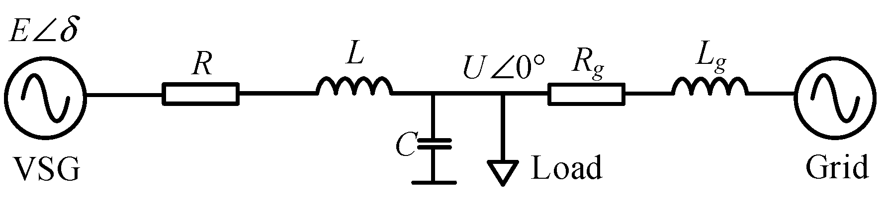
2. Topology and Mathematical Model of VSG

2.1. Topology of VSG

A traditional VSG system is shown in Figure 1. The main circuit of the system consists of a DC source, voltage-type converter, filter circuit, load, and power grid. The control loop collects the output voltage, current, active power, reactive power, and other signals of the main circuit; generates modulation signals through the virtual governor, excitation controller, voltage and current double-loop controller; and finally generates the pulse signal to control the converter [19,20]. Topology and control block diagram of Figure 1: Labc is the filter inductor; Cabc is the filter capacitor; Pe and Qe are the active and reactive power output by the converter, respectively; iabc_inv and uabc_inv are the output current and voltage, K is the integral loop coefficient, Un is the amplitude of the given voltage, Uinv is the RMS value of the three-phase voltage output from the converter, Rr is the stator resistance; Lr is the inductance, Rg is the line resistance, Lg is the line inductance; ug is the grid voltage, iLabc is the inductor current, uabc_ref is the modulation voltage reference, gPWM is the modulation signal.

2.2. Mathematical Model of VSG

The stator electrical equation and the typical second-order rotor motion equation of the synchronous generator are [6]:
e = u + i R + j ω L T m T e = P m P e ω = J d ω d t + D Δ ω Δ ω = ω ω N d δ d t = ω
Among them, R is the stator resistance; L is the inductance; u is the armature terminal voltage; Tm is the mechanical torque; Te is the electromagnetic torque; J is the moment of inertia; D is the damping coefficient; ω is the mechanical angular velocity; ωN is the rated angular velocity of the system; δ is the output power angle.
As shown in Figure 1, drawing on the principles of the synchronous generator governor and excitation regulator, the active power regulation and reactive power regulation equations are designed so that the entire converter system can truly simulate the characteristics of the synchronous generator.
ω = 2 π f E = K s Q ref + K V U n U inv Q e Δ T = P ref + K P ω N ω P e / ω
In (2), Pref and Qref are the system active and reactive commands respectively; KV is the voltage regulation coefficient; KP is the active power droop coefficient; K is the integral loop coefficient; E is the virtual potential command; Un is the amplitude of the given voltage; Uinv is the effective value of the three-phase voltage output by the converter; f is the frequency of the terminal voltage of the virtual synchronous generator.
Finally, after combining the above-obtained voltages in the voltage synthesis link reference value and phase angle, the output voltage of VSG can be obtained as
e = 2 E sin δ 2 E sin δ 2 π 3 2 E sin δ + 2 π 3

3. Multiparameter Cooperative Adaptive Control of VSG

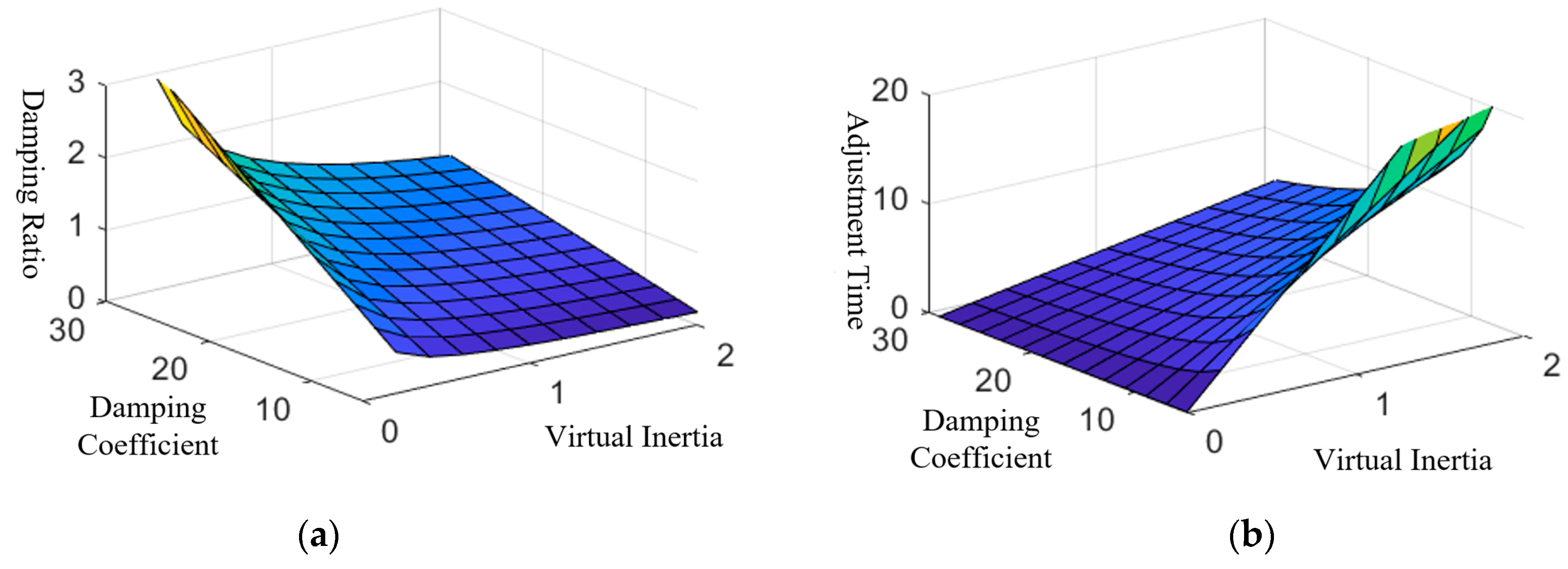
3.1. The Influence of VSG Parameters on the System

According to the equivalent diagram in Figure 2, the output active power of the grid-connected inverter of VSG can be expressed as:
P e = E U X sin δ
Combining Formulas (1) and (4), we can obtain:
Δ ω Δ P = ω N ω P ref P e = 1 J ω N s + D ω N + K P
Therefore, the closed-loop transfer function of the VSG active loop can be deduced as:
φ s = P e P ref = E U J ω N X s 2 + D ω N + K P J ω N s + E U J ω N X
The corresponding natural oscillation angular frequency and damping ratio are:
ξ = 0.5 D ω N + K P J ω N E U X ω n = E U J ω N X
When 0 < ξ < 1, the power-frequency system is an underdamped system; when ξ = 1, the power-frequency system is a critically damped system; When ξ > 1, the power-frequency system is an overdamped system. Considering the two dynamic indicators of response speed and overshoot, the “Siemens second-order optimal system” control strategy is adopted, that is, the damping ratio is set to 0.707. Among them, in the underdamped state, within a certain allowable error, the adjustment time ts and σ% are:
t s = 4 ξ ω n = 8 J ω N D ω N + K P σ % = e π ξ 1 ξ 2 × 100 %
When the droop coefficient is constant, it can be seen from Figure 3a that the damping ratio ξ of the VSG system is proportional to the damping coefficient D and inversely proportional to the virtual inertia J.
While the system adjustment time in Figure 3b is the opposite, it is proportional to the virtual inertia J and inversely proportional to the damping coefficient D.
The above analysis does not consider the influence of the droop coefficient on the dynamic response of the system. Combining Formulas (7) and (8), it can be known that when the virtual inertia and damping coefficient are constant, the damping ratio increases with the increase of the droop coefficient, and the adjustment time decreases with the increase of the droop coefficient. Relative to the damping ratio, the system adjustment time is more deeply affected by the droop factor.
It can be seen from the above analysis that the virtual inertia J, damping coefficient D, and droop coefficient KP in the traditional virtual synchronous machine control strategy remain unchanged. If any one of the values is changed alone, although the transient characteristics of the VSG grid connection can be significantly improved, it cannot take into account the stability and rapidity of the transient process after the system is disturbed.

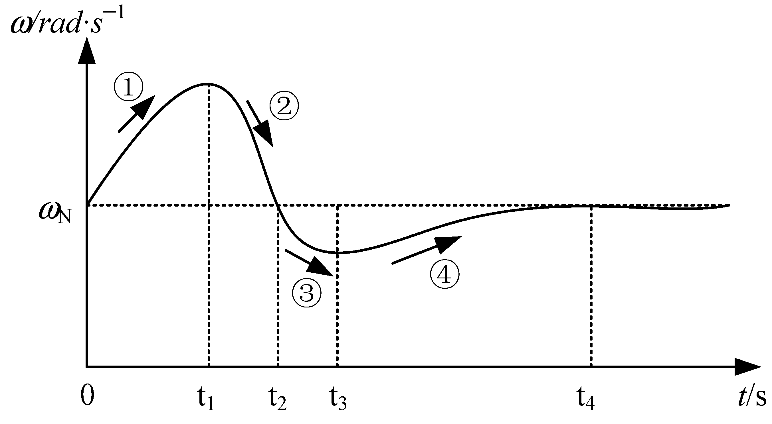
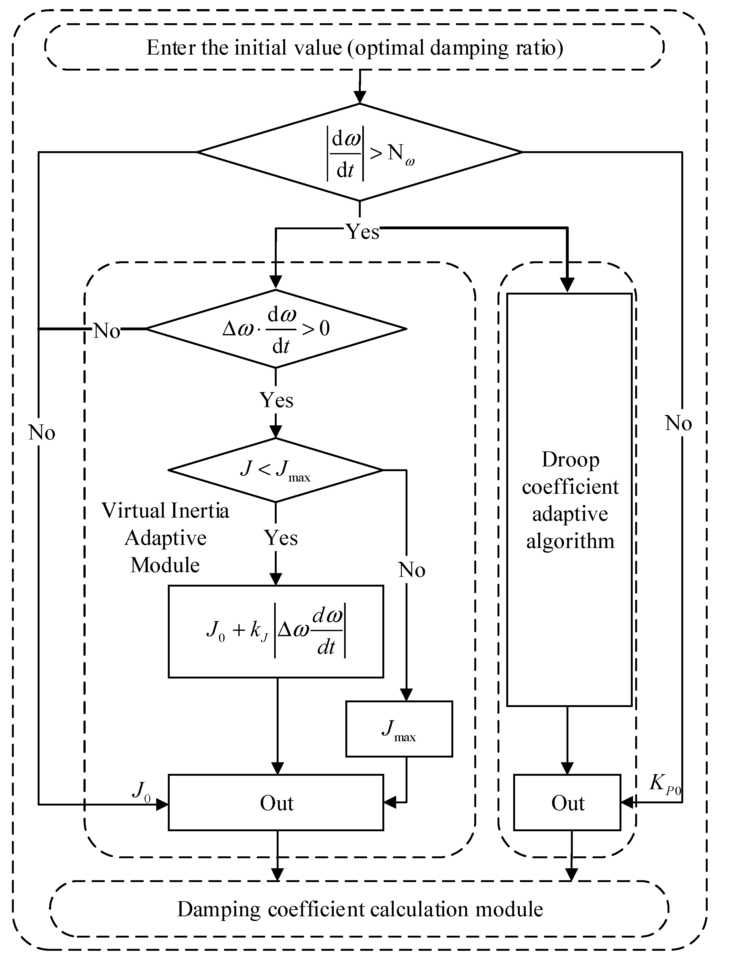
3.2. Cooperative Adaptive Selection Strategy of Control Parameters

In this paper, the frequency oscillation process of VSG is divided into four different stages, as shown in Figure 4. The characteristics of the different phases are analyzed, the virtual inertia J and the droop coefficient KP are adjusted in real time, and the damping coefficient D is coordinated according to the relationship between the three to achieve stable control of the grid-connected VSG transient process.
Δω·/dt > 0 exists in both stage 1 and stage 3 and |Δω| gradually increases in both stages. These two stages are defined as the acceleration stage of rotor angular velocity. This stage requires larger virtual inertia J and larger droop coefficient KP to reduce the amplitude of rotor angular velocity offset.
Δω·/dt < 0 exists in both stage 2 and stage 4. Since |Δω| gradually decreases, the two stages are defined as the deceleration stage of rotor angular velocity. In this stage, the virtual inertia J and the droop coefficient KP need to be reduced to make the rotor angular velocity return to a stable value as soon as possible.
However, in the acceleration stage of the rotor, although the increase in inertia can improve the anti-interference, it will reduce the response speed. In this stage, the damping method can be used to improve the response speed.
In the deceleration stage, the virtual inertia J and the droop coefficient KP are reduced, and the system’s suppression of the fluctuation of the rotor angular velocity is weakened to speed up the decay rate of the rotor angular velocity; nevertheless, it will cause an increase in the amplitude of the fluctuation of the rotor angular velocity. Therefore, at this stage, the damping coefficient can be increased to reduce the overshoot of the system and make the frequency return to stability as soon as possible.
The selection of J is determined by Δω and /dt at the same time. In order to avoid the complicated control strategy, the change rule is set as:
  • When Δω and /dt change in the same direction, J needs to be increased;
  • When Δω and /dt change in opposite directions, J should be kept unchanged.
The virtual inertia J and the droop coefficient KP are associated with the VSG angular velocity and the instantaneous value of the angular velocity to obtain the control parameter adaptive strategy, as shown in Formulas (9) and (10).
J = J 0 + k J Δ ω d ω d t , Δ ω d ω d t > 0 J 0 , Δ ω d ω d t 0
K P = K P 0 + k ω Δ ω
In the formulas, J0 and KP0 are the virtual inertia and droop coefficient of VSG fixed parameters, respectively; kJ is the inertia adjustment coefficient and kω is the adjustment coefficient of the droop coefficient.
The coordinated control design of the droop coefficient, virtual inertia, and damping coefficient is carried out. Combining Formulas (7), (9) and (10), the damping coefficient D design under the correlation can be obtained:
D = 2 ξ J E U ω N X 1 ω N K P
Based on automatic control theory, in order to keep the system in the optimal control operation state, ξ can be set to 0.707. It can be known from Formula (11) that when other parameters in the system are constant, the droop coefficient, virtual inertia, and damping coefficient can be jointly designed according to the requirements of system characteristics.

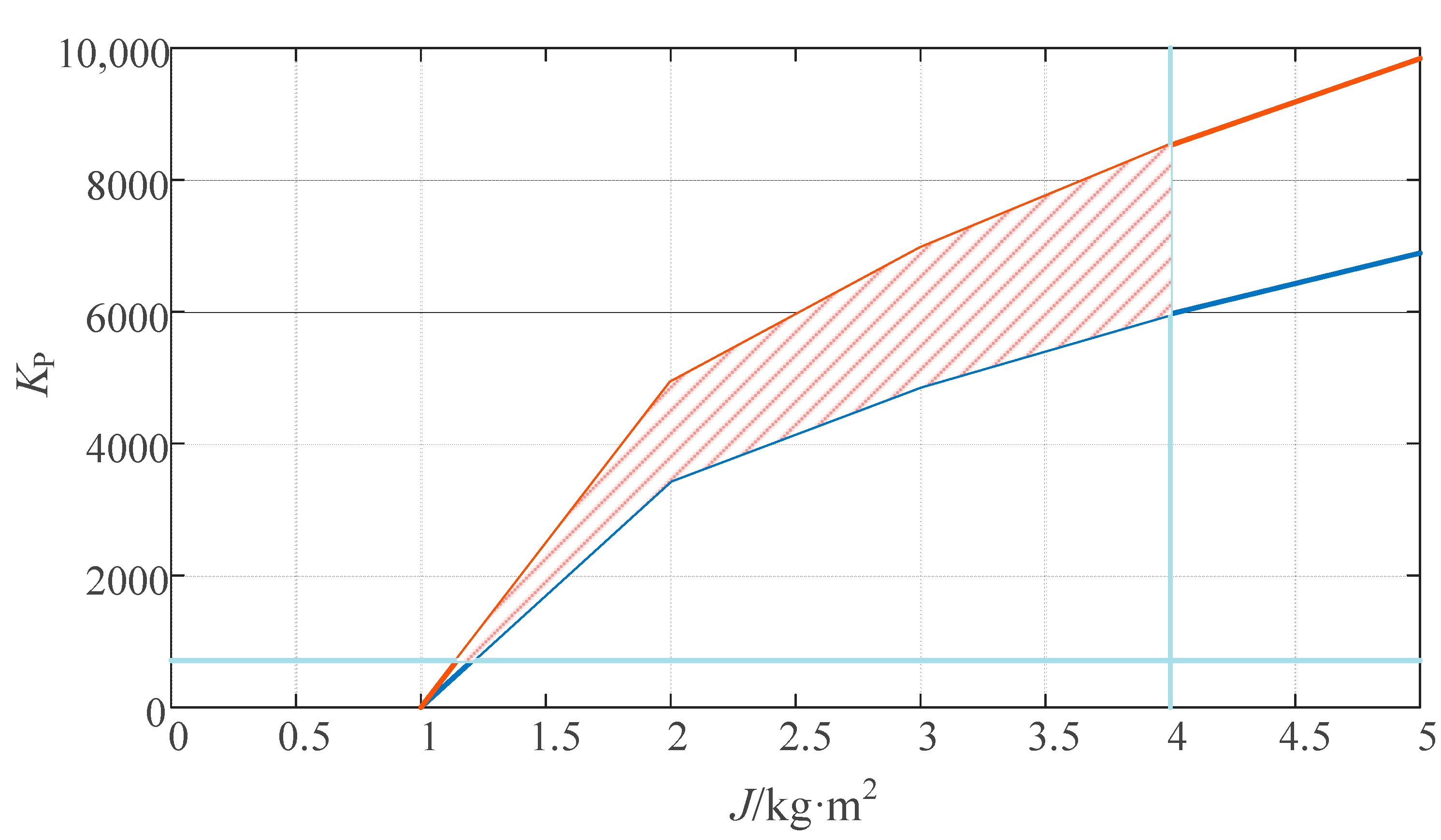
3.3. The Setting of Parameter Value Range

The adaptive adjustment coefficient of VSG inertia can be selected according to the value range of inertia. According to the setting principle of the virtual inertia value of the VSG scheme of the University of Leuven [21], the maximum value of the virtual inertia must satisfy:
J max < P max max ω d ω d t
In Formula (12), Pmax is the maximum power that the system can withstand. In order to ensure the stable operation of the system, the angular frequency of the system is limited with reference to the current national standard power system frequency deviation (50 ± 0.2 Hz).
The maximum and minimum frequencies are ωmax and ωmin, respectively; then, the damping coefficient selection in Formula (10) should satisfy Formula (13):
0 1 D ω N + K P ω max ω min P max P min
In Formula (13), Pmin is the minimum output power of VSG. Therefore, the minimum value of the damping coefficient D is:
P max P min ω max ω min K P / ω N D
And the droop factor shall also be taken to satisfy Formula (15):
K P P max / Δ ω max
In addition, in order to make the system have good response rapidity, each transient component of its response should have a large decay factor—that is, the closed-loop pole of the system should be far away from the imaginary axis, and the closed-loop pole should satisfy [22,23,24,25]:
Re s i = ω n ξ = D + K P / ω N 2 J 10
In VSG control, moderate damping, a fast response, and a small overshoot are usually desired in the control system. The damping ratio ξ is therefore chosen to be in the range (0.7, 1). In summary, the range of virtual inertia J and droop factor KP can be obtained as shown in Figure 5.
To sum up, the flow chart of the core algorithm in this paper is shown in Figure 6, where Nω is the threshold for setting a triggering adaptive function.
Based on the above design, the bode diagram of the whole system is shown in Figure 7. In the figure, the amplitude margin as well as the phase margin of the control strategy proposed in this paper is the largest, so that the error value is the smallest and not prone to damped oscillations, resulting in the highest stability and the best system performance. Fuzzy adaptive optimal control is the next most effective control strategy. Traditional adaptive control is the least effective.

4. Simulation Analysis

In order to verify the control strategy proposed in this paper, an improved VSG system simulation model on the MATLAB/Simulink platform is built into this work, and the relevant control parameters used are shown in Table 1.
The system is in a grid-connected operation state, the simulation duration is set to 2 s, the initial steady state is assumed, and the grid frequency is equal to the rated frequency. In order to simulate the change in load power, the load power is set to increase by 10 kW at 1 s, and the reactive power is constant at 0 kVar during this period.

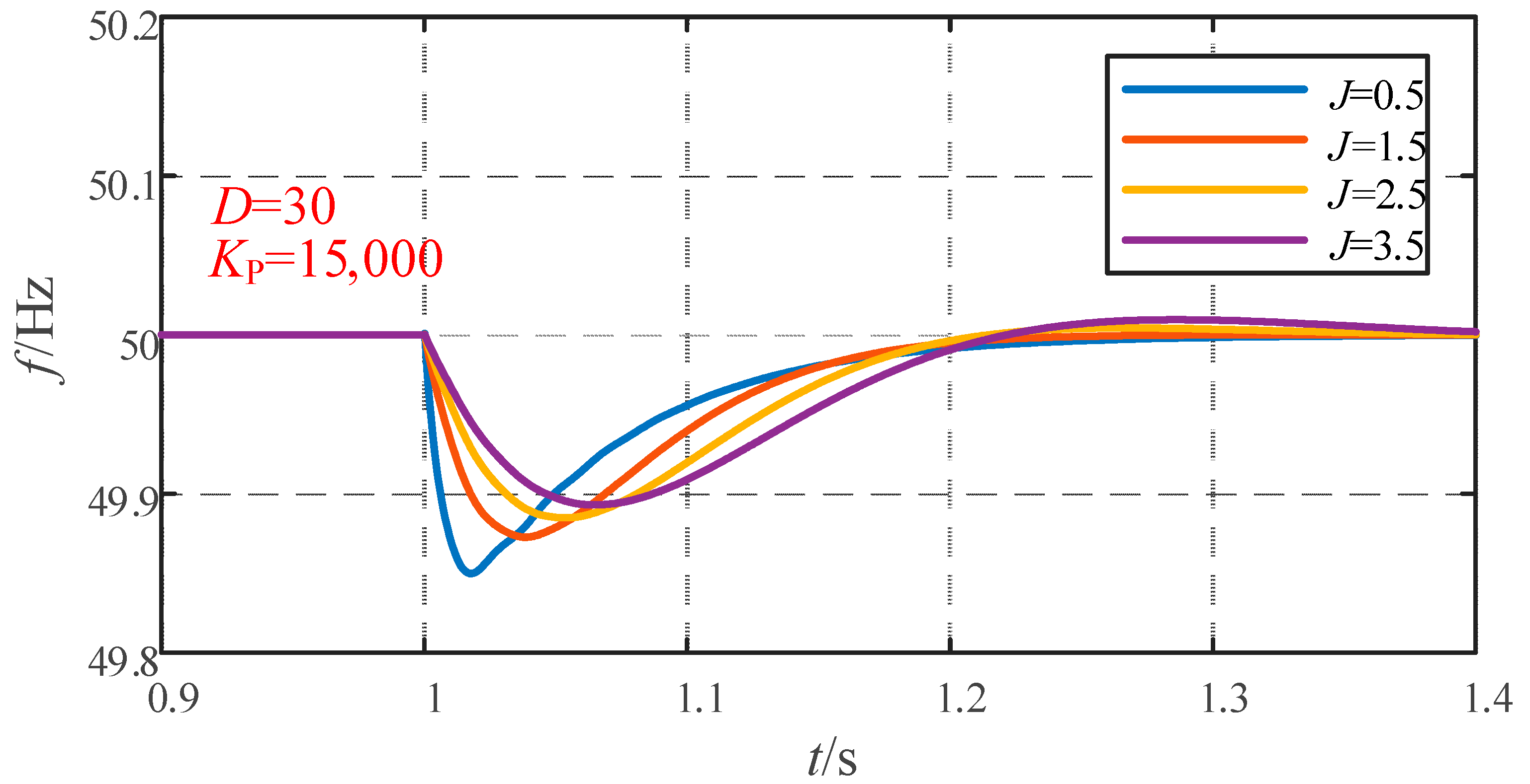
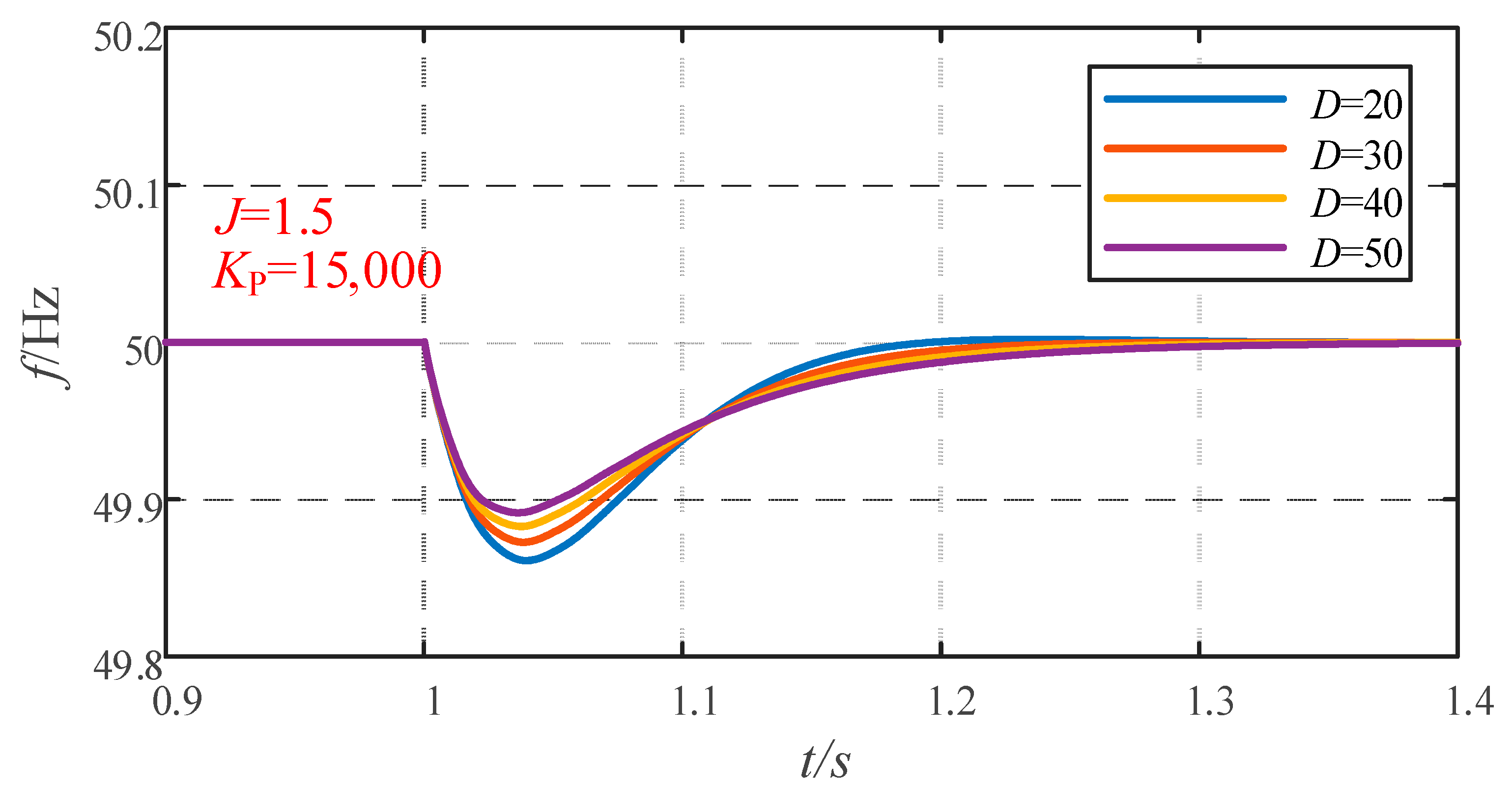
4.1. Effect of Changes in System Parameters on System Frequency

Figure 8, Figure 9 and Figure 10 show the frequency variation curve of the system with different inertia, damping, and droop coefficient. When the virtual damping D and droop factor KP are fixed, the greater the virtual inertia J is, the longer the dynamic adjustment time is, but the frequency overshoot is reduced. The system transitions from an overdamped state to an underdamped state, as shown in Figure 8.
When the virtual inertia J and sag factor KP are fixed, the smaller the virtual damping D is, the longer the dynamic adjustment time is, and the greater the frequency overshoot is, the system transitions from an overdamped state to an underdamped state, as shown in Figure 9.
When the virtual inertia J and virtual damping D are fixed, the larger the sag coefficient KP is, the smaller the frequency overshoot is, as shown in Figure 10. The correctness of the theoretical analysis in this paper is verified.

4.2. Simulation under Varying System Loads

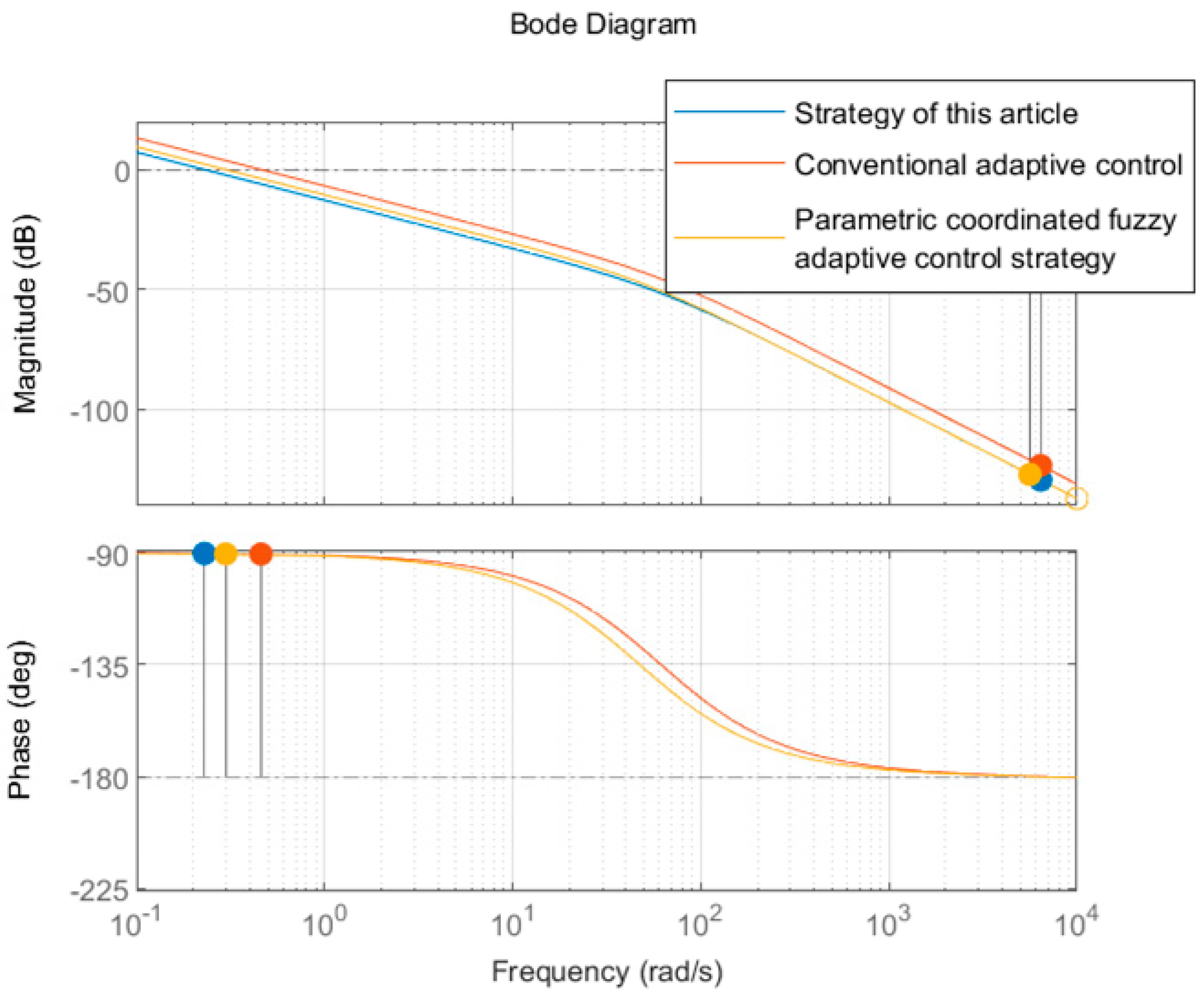
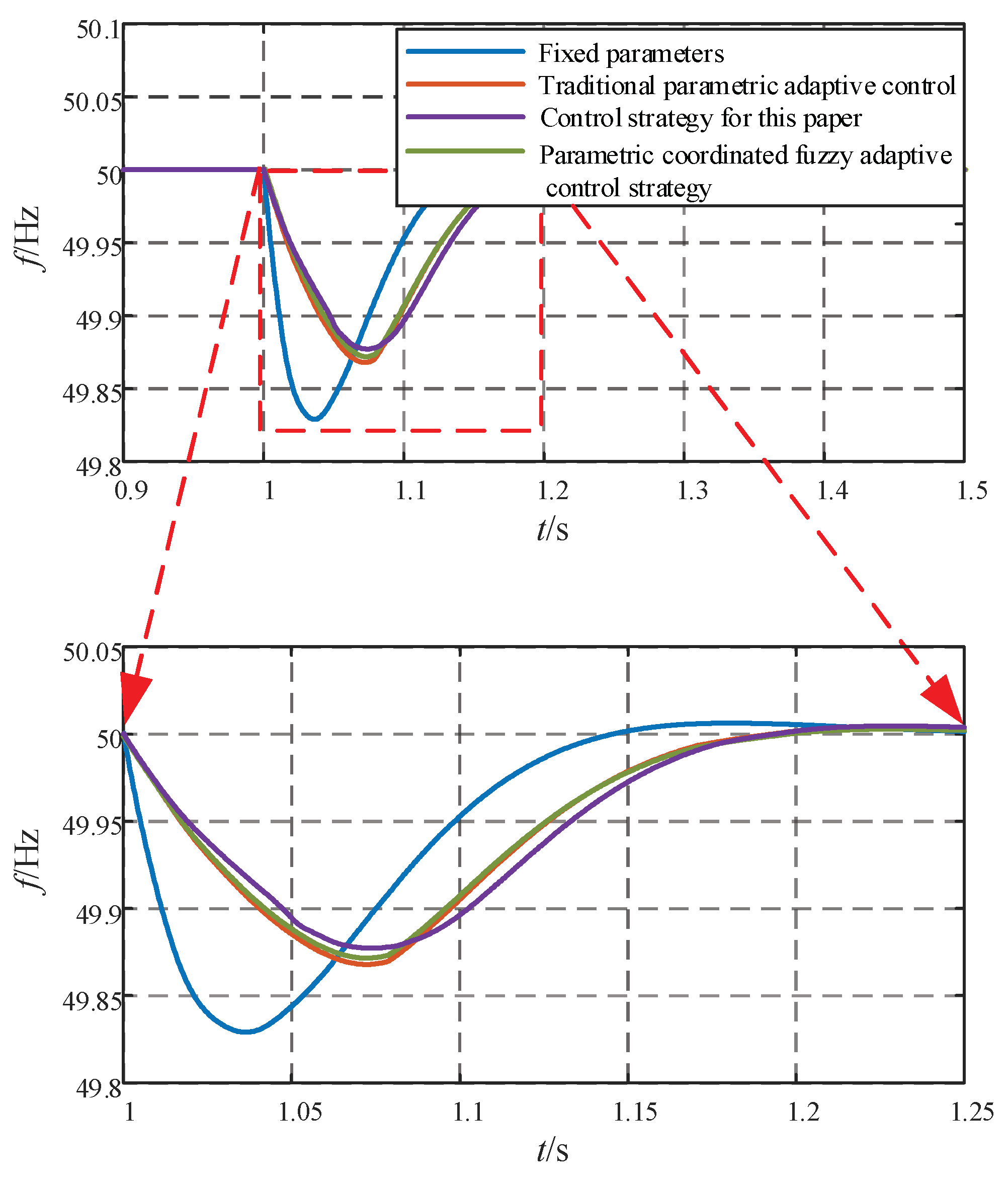
4.2.1. Simulation Comparison of Different Control Strategies

In order to verify the superiority of this control strategy in grid-connected mode, it is compared with coordinated inertia damping (ξ = 0.707), J and D coordinated adaptive control and parametric coordinated fuzzy adaptive control strategy, respectively. The frequency change is shown in Figure 11.
The frequency change curve and a partially enlarged view can be seen in Figure 11. It can be seen from Figure 11 that the coordinated inertia damping (ξ = 0.707) control strategy is adopted—when the parameters are fixed, the maximum offset of the frequency fluctuation reaches 0.17 Hz, and it takes about 0.3 s to reach the steady state. When using J and D coordinated adaptive control, the maximum frequency offset is reduced to 0.133 Hz, and the adjustment time is about 0.22 s. When using a parametric coordinated fuzzy adaptive control strategy, the maximum frequency offset is reduced to 0.132 Hz, and the adjustment time remains the same. When the multiparameter cooperative adaptive control strategy is adopted, the maximum frequency offset is 0.123 Hz, and the adjustment time is 0.22 s. The specific performance indicators are shown in Table 2.
The maximum deviation of the multiparameter cooperative adaptive control is optimized by 7.52% compared with the J and D coordinated adaptive control and is optimized by 27.65% compared with the coordinated inertia damping (ξ = 0.707) control strategy. The adjustment time of the multiparameter cooperative adaptive control is equivalent to that of the J and D coordinated adaptive control and is 26.67% higher than that of the coordinated inertia damping control.

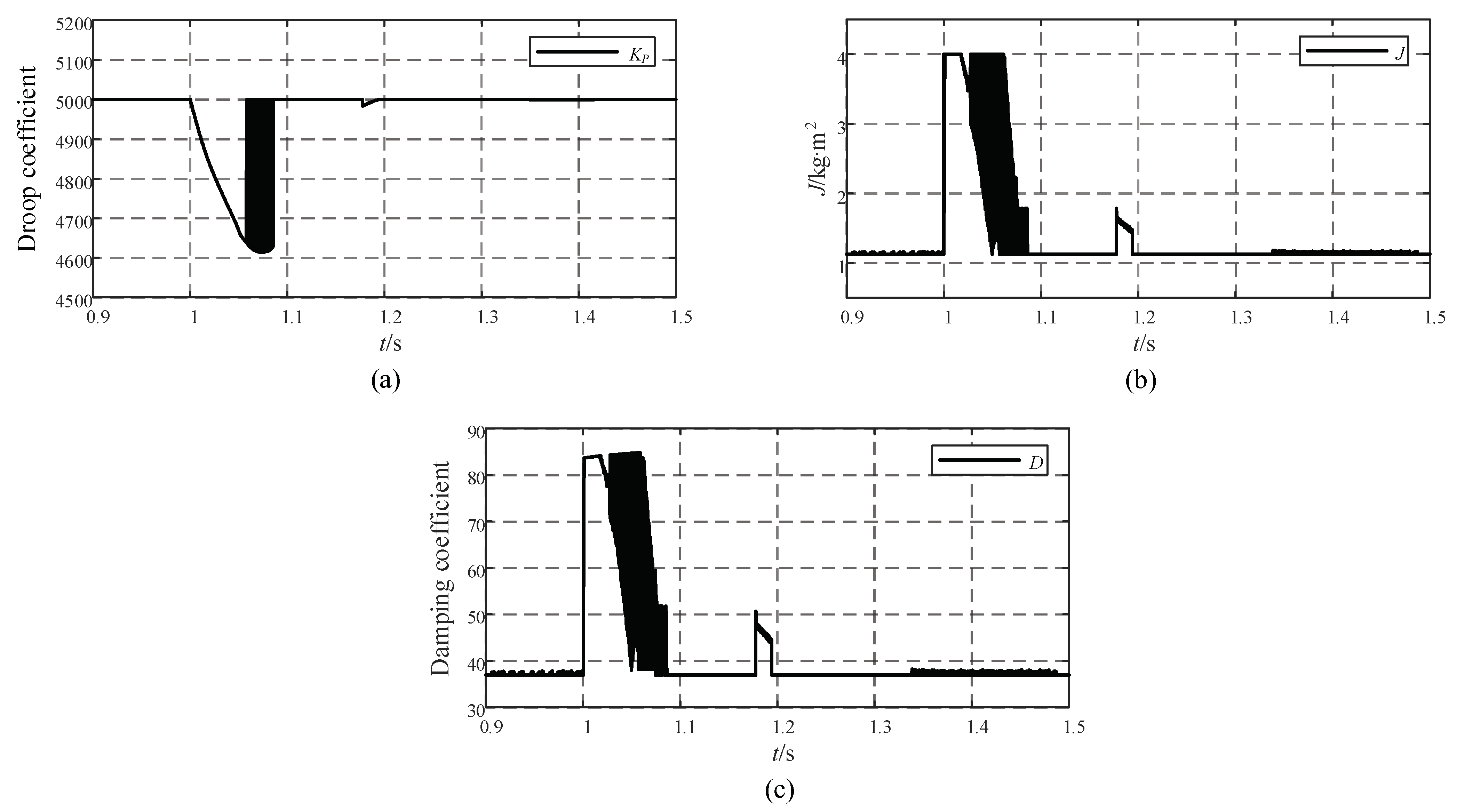
4.2.2. Comparison of Parameter Changes

Figure 12 and Figure 13 show the variation of the J and D coordinated adaptive control parameters and the variation of the multiparameter collaborative adaptive control parameters in this paper, respectively.
Figure 12, as well as Figure 13b,c, shows the frequency change caused by the load change at 1 s; the angular frequency rate of change and frequency offset are both negative, and in the angular frequency acceleration phase, the virtual inertia and damping coefficient increase rapidly. During the frequency fluctuation, when the angular frequency rate of change and frequency offset have different signs, the virtual inertia and damping coefficient decrease rapidly in the angular frequency deceleration stage.
However, when J and D adaptive control is in a perturbation cycle of the change process, during the same moment only one quantity changes (that is, the control for alternate), other quantities are not affected. This control system is simple, ignoring the influence of the droop coefficient.
It also can be seen from Figure 13a that the droop coefficient will have a corresponding adaptive change when the frequency changes caused by the load change, to further synergistically optimize the damping coefficient. During dynamic changes, the droop coefficient varies continuously in the range of 4600 to 5000, and the virtual inertia varies in the range of 1 to 4, while the damping coefficient varies in the range of 38 to 85 under the combined effect of both.

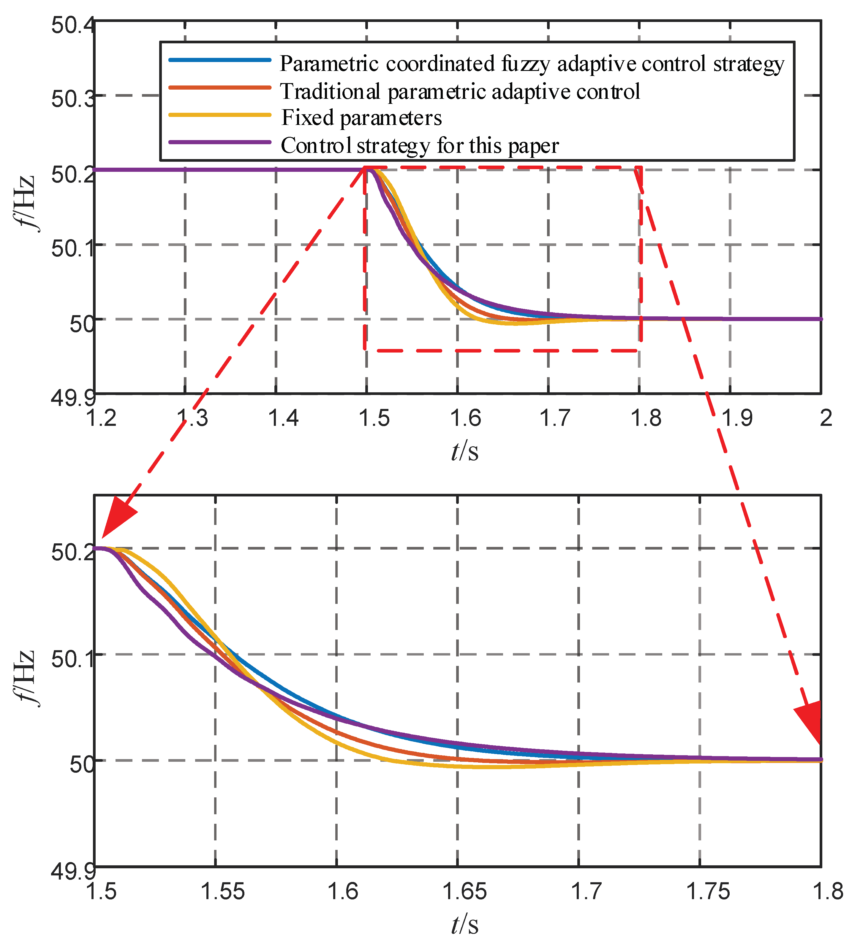
4.3. Simulation under Grid Frequency Variation

To further verify the performance of the proposed control strategy, the grid frequency was simulated: at 0.5 s, the grid frequency increased by 0.2 Hz, and after 1 s, the frequency returned to 50 Hz.

4.3.1. System Frequency Performance

The frequency change curve and a partially enlarged view can be seen in Figure 14. As can be seen from the graph, frequency overshoot exists using the fixed parameter control strategy; when using conventional adaptive control, the overshoot is reduced. The rate of change in frequency is greater for both of these approaches. When using fuzzy adaptive control and the strategy proposed in this paper, there is no overshoot in the frequency, and the frequency variation rate of the system is minimal under the control strategy proposed in this paper.

4.3.2. Variation of the Three Parameters

It can also be seen in Figure 15a that the VSG needs to adjust its output when the grid frequency rises by 0.2 Hz throughout; therefore, it needs to adjust the droop coefficient, which varies dynamically between 5000 and 5600. The virtual inertia also varies at this point between around 1.1 and 3.9, as shown in Figure 15b. The damping coefficient is adjusted in real time according to the mathematical logic between the three and varies between 36 and 82, as shown in Figure 15c. Unlike the load variation, the sag coefficient, virtual inertia, and the damping coefficient keep interacting with each other throughout the process, without stopping to vary when the frequency is stable.

5. Conclusions

Although the traditional virtual synchronous generator technology can improve the stability of the system by simulating the operating characteristics of the synchronous generator, it has problems, such as the inability to take into account multiple performance indicators for parameter design, long adjustment time, and large transient overshoot. To address these problems, this paper uses an improved VSG parameter optimization cooperative control strategy, and the effectiveness of this control strategy is verified by simulation through simulated load variation and frequency variation. The main work and contributions are as follows:
(1)
Analyze the effect of droop factor, virtual inertia, and damping factor on the VSG system and determine the range of values for the system parameters.
(2)
The existing J and D coordinated adaptive control is optimized. The droop coefficient and virtual inertia can be adjusted in real time according to the system frequency state, and the damping coefficient can be changed cooperatively according to the corresponding relationship. The three are always coordinated and adjusted during the change process, which effectively improves the dynamic performance of the system frequency. The effectiveness and reliability of the proposed multiparameter cooperative adaptive control strategy have been verified by simulation.

Author Contributions

Conceptualization, B.R. and Z.F.; methodology, Q.L.; software, Y.S.; validation, B.R., Z.F. and Y.S.; formal analysis, Q.L.; investigation, B.R.; resources, Q.L.; data curation, Q.L.; writing—original draft preparation, B.R.; writing—review and editing, Y.S.; visualization, B.R.; supervision, Y.S.; project administration, Y.S.; funding acquisition, Y.S. All authors have read and agreed to the published version of the manuscript.

Funding

This work was supported by the Science and Technology Project of State Grid Jiangsu Electric Power Company Limited (J2021177) (Research on the influence mechanism of high aggregation access of offshore wind farms on the inertia of Jiangsu Power grid and key technologies to improve the accommodation capacity).

Data Availability Statement

Not applicable.

Conflicts of Interest

The authors declare no conflict of interest.

References

  1. Yang, X.Z.; Su, J.H.; Ding, M. Frequency control strategy for microgrid island operation. Power Syst. Technol. 2010, 34, 164–168. [Google Scholar]
  2. Sun, H.D.; Xu, T.; Guo, Q. Analysis on blackout in Great Britain power grid on August 9th, 2019 and its enlightenment to power grid in China. Proc. CSEE 2019, 39, 6183–6191. [Google Scholar]
  3. Wen, Y.F.; Yang, W.F.; Lin, X.H. Review and prospect of frequency stability analysis and control of low-inertia power systems. Electr. Power Autom. Equip. 2020, 40, 211–222. [Google Scholar]
  4. Zhong, Q.C.; Nguyen, P.L.; Ma, Z.Y. Selfsynchronized synchronverters: Inverters without a dedicated synchronization unit. IEEE Trans. Power Electron. 2014, 29, 617–630. [Google Scholar] [CrossRef]
  5. Du, W.; Jiang, Q.R.; Chen, J.R. Design and application of reactive power control system for wind farm. Autom. Electr. Power Syst. 2011, 35, 26–31. [Google Scholar]
  6. Ren, H.P.; Chen, Q.; Zhang, L.L. Parameter adaptive strategy for virtual synchronous generator control. Control Theory Appl. 2020, 37, 2571–2580. [Google Scholar]
  7. Wang, F.; Zhang, L.J.; Feng, X.Y. An adaptive control strategy for virtual synchronous generator. IEEE Trans. Ind. Appl. 2018, 54, 5124–5133. [Google Scholar] [CrossRef]
  8. Alipoor, J.; Miura, Y.; Ise, T. Power system stabilization using virtual synchronous generator with alternating moment of inertia. IEEE J. Emerg. Sel. Top. Power Electron. 2015, 3, 451–458. [Google Scholar] [CrossRef]
  9. Zhu, Z.B.; Zhang, C.Y.; Zeng, X.B. Photovoltaic energy storage microgrid system based on adaptive rotating inertia VSG control strategy. Proc. CSU-EPSA 2021, 33, 67–72. [Google Scholar]
  10. Zhou, P.G.; Meng, J.H.; Wang, Y. Influence analysis of the main control parameters in FVSG on the frequency stability of the system. High Volt. Eng. 2018, 44, 1335–1342. [Google Scholar]
  11. Yang, Y.; Mei, F.; Zhang, C.Y. Coordinated adaptive control strategy of rotational inertia and damping coefficient for virtual synchronous generator. Electr. Power Autom. Equip. 2019, 39, 125–131. [Google Scholar]
  12. Li, D.D.; Zhu, Q.W.; Lin, S.F. A self-adaptive inertia and damping combination control of VSG to support frequency stability. IEEE Trans. Energy Convers. 2017, 32, 397–398. [Google Scholar] [CrossRef]
  13. Li, Z.J.; Yang, M.W.; Zhang, J.A.; Liu, H.J. Research on the cooperative adaptive control of VSG inertia and damping. J. Electr. Power Syst. Autom. 2023, 35, 36–43. [Google Scholar]
  14. Zhang, X.W.; Tan, L.P.; Chen, W.H.; Liu, Y.; Liu, M.S. Inertia lifting method of energy storage converter based on secondary system optimization. Power Syst. Prot. Control 2021, 49, 128–135. (In Chinese) [Google Scholar]
  15. Fan, Y.N.; Liu, T.Y.; Jiang, X.C.; Sheng, G.H.; Zhang, X.S. Optimal control strategy based on optimal damping ratio dummy synchronous generator. Electr. Meas. Instrum. 2020, 57, 60–67. (In Chinese) [Google Scholar]
  16. He, P.; Li, Z.; Jin, H.R.; Zhao, C.; Fan, J.L.; Wu, X.P. An adaptive VSG control strategy of battery energy storage system for power system frequency stability enhancement. Int. J. Electr. Power Energy Syst. 2023, 149, 142–615. [Google Scholar] [CrossRef]
  17. Zhang, Y.N.; Sun, X.L.; Fu, W.L.; Hu, S.L. Parametric coordinated fuzzy adaptive VSG control strategy. Electron. Meas. Technol. 2022, 45, 1–7. (In Chinese) [Google Scholar]
  18. Peng, C.; Hu, L.R.; Zhang, L.M.; Wang, B.H. Adaptive damping control of microgrid based on distributed VSG. Power Electron. Technol. 2023, 57, 85–88. (In Chinese) [Google Scholar]
  19. Shao, Y.Y. Research on Energy Storage Inverter Control Based on Virtual Synchronous Generator; Zhejiang University: Hangzhou, China, 2021. [Google Scholar]
  20. Zhang, G.F.; Yang, J.Y.; Wang, H.X.; Xie, C.J.; Fu, Y. Coordinated Frequency Modulation Control Strategy of Wind Storage System Based on Virtual Synchronous Machine Technology. J. Electrotech. Technol. 2022, 37, 83–92. [Google Scholar]
  21. Lü, Z.P.; Sheng, W.X.; Zhong, Q.C. Virtual synchronous generator and its applications in micro-grid. Proc. CSEE 2014, 34, 2591–2603. (In Chinese) [Google Scholar]
  22. Du, Y.; Su, J.H.; Zhang, L.C. A mode adaptive frequency controller for microgrid. Proc. CSEE 2013, 33, 67–75. [Google Scholar]
  23. Xu, H.Z.; Zhang, X.; Liu, F. Virtual Synchronous Generator Control Strategy Based on Lead-lag Link Virtual Inertia. Proc. CSEE 2017, 37, 1918–1927. (In Chinese) [Google Scholar]
  24. Xu, H.Z.; Zhang, X.; Liu, F. Control strategy of virtual synchronous generator based on differential compensation virtual inertia. Autom. Electr. Power Syst. 2017, 41, 96–102. (In Chinese) [Google Scholar]
  25. Xu, H.; Yu, C.; Liu, C.; Wang, Q.; Zhang, X. An Improved Virtual Inertia Algorithm of Virtual Synchronous Generator. J. Mod. Power Syst. Clean Energy 2020, 8, 377–386. [Google Scholar] [CrossRef]
Figure 1. Topology and control block diagram of VSG.
Energies 16 04789 g001
Figure 2. Equivalent diagram of VSG-connected to the grid.
Energies 16 04789 g002
Figure 3. (a) Plot of damping ratio versus virtual inertia and damping coefficient. (b) Plot of adjustment time versus virtual inertia and damping coefficient.
Energies 16 04789 g003
Figure 4. Angular velocity fluctuation graph.
Energies 16 04789 g004
Figure 5. The range of virtual inertia J and droop factor KP.
Energies 16 04789 g005
Figure 6. Core algorithm flow chart.
Energies 16 04789 g006
Figure 7. Bode diagram of the system.
Energies 16 04789 g007
Figure 8. Frequency waveform under J change.
Energies 16 04789 g008
Figure 9. Frequency waveform under D change.
Energies 16 04789 g009
Figure 10. Frequency waveform under KP change.
Energies 16 04789 g010
Figure 11. Frequency variation under different control strategies.
Energies 16 04789 g011
Figure 12. J and D coordinated adaptive control parameter variation: (a) virtual inertia change curve; (b) damping coefficient change curve.
Energies 16 04789 g012
Figure 13. (a) Droop coefficient change curve. (b) Virtual inertia change curve. (c) Damping coefficient change curve.
Energies 16 04789 g013
Figure 14. Frequency curves.
Energies 16 04789 g014
Figure 15. (a) Droop coefficient change curve. (b) Virtual inertia change curve. (c) Damping coefficient change curve.
Energies 16 04789 g015
Table 1. Simulation parameters of VSG.
ParameterNumerical ValueParameterNumerical Value
Rated voltage on AC grid ug (V)380Filter inductor Labc(mH)0.8
Rated voltage on DC side Udc (V)800Filter capacitor Cabc (uF)10
Rated active power (W)50,000Initial value of virtual inertia J0 (kg·m2)1.127
Rated reactive power (Var)0Initial value of droop coefficient KP05000
Table 2. Control strategy performance indicators.
Control StrategyNadir (Hz)Deviation (Hz)Adjustment Time (s)ROCOF
Fixed parameters49.830.170.3maximum
J, D adaptive control49.8670.1330.22medium
Parametric coordinated fuzzy adaptive control strategy49.8680.1320.22medium
Multiparameter cooperative adaptive control49.8770.1230.22minimum
Disclaimer/Publisher’s Note: The statements, opinions and data contained in all publications are solely those of the individual author(s) and contributor(s) and not of MDPI and/or the editor(s). MDPI and/or the editor(s) disclaim responsibility for any injury to people or property resulting from any ideas, methods, instructions or products referred to in the content.

